EP0370124A1 - Computer-Tomograph - Google Patents
Computer-Tomograph Download PDFInfo
- Publication number
- EP0370124A1 EP0370124A1 EP88119417A EP88119417A EP0370124A1 EP 0370124 A1 EP0370124 A1 EP 0370124A1 EP 88119417 A EP88119417 A EP 88119417A EP 88119417 A EP88119417 A EP 88119417A EP 0370124 A1 EP0370124 A1 EP 0370124A1
- Authority
- EP
- European Patent Office
- Prior art keywords
- focus
- ray emitter
- computer
- measured values
- computer tomograph
- Prior art date
- Legal status (The legal status is an assumption and is not a legal conclusion. Google has not performed a legal analysis and makes no representation as to the accuracy of the status listed.)
- Granted
Links
Images

Classifications
-
- A—HUMAN NECESSITIES
- A61—MEDICAL OR VETERINARY SCIENCE; HYGIENE
- A61B—DIAGNOSIS; SURGERY; IDENTIFICATION
- A61B6/00—Apparatus for radiation diagnosis, e.g. combined with radiation therapy equipment
- A61B6/02—Devices for diagnosis sequentially in different planes; Stereoscopic radiation diagnosis
- A61B6/03—Computerised tomographs
- A61B6/032—Transmission computed tomography [CT]
-
- A—HUMAN NECESSITIES
- A61—MEDICAL OR VETERINARY SCIENCE; HYGIENE
- A61B—DIAGNOSIS; SURGERY; IDENTIFICATION
- A61B6/00—Apparatus for radiation diagnosis, e.g. combined with radiation therapy equipment
- A61B6/40—Apparatus for radiation diagnosis, e.g. combined with radiation therapy equipment with arrangements for generating radiation specially adapted for radiation diagnosis
- A61B6/4021—Apparatus for radiation diagnosis, e.g. combined with radiation therapy equipment with arrangements for generating radiation specially adapted for radiation diagnosis involving movement of the focal spot
- A61B6/4028—Apparatus for radiation diagnosis, e.g. combined with radiation therapy equipment with arrangements for generating radiation specially adapted for radiation diagnosis involving movement of the focal spot resulting in acquisition of views from substantially different positions, e.g. EBCT
-
- H—ELECTRICITY
- H05—ELECTRIC TECHNIQUES NOT OTHERWISE PROVIDED FOR
- H05G—X-RAY TECHNIQUE
- H05G1/00—X-ray apparatus involving X-ray tubes; Circuits therefor
- H05G1/08—Electrical details
- H05G1/26—Measuring, controlling or protecting
-
- H—ELECTRICITY
- H05—ELECTRIC TECHNIQUES NOT OTHERWISE PROVIDED FOR
- H05G—X-RAY TECHNIQUE
- H05G1/00—X-ray apparatus involving X-ray tubes; Circuits therefor
- H05G1/08—Electrical details
- H05G1/26—Measuring, controlling or protecting
- H05G1/30—Controlling
- H05G1/52—Target size or shape; Direction of electron beam, e.g. in tubes with one anode and more than one cathode
Definitions
- the invention relates to a computer tomograph with an x-ray emitter with a circular anode arc enclosing a measurement opening, on which the focus for moving an object lying in the measurement opening is moved with a fan-shaped x-ray beam under different directions with the aid of a deflection system, and with a circular radiation detector there is a series of detector elements, the measured values of which are fed via a data acquisition system to a computer which calculates the attenuation values of predetermined points of the examined object layer and effects their visual reproduction.
- the invention is based on the object of designing a computer tomograph of the type mentioned at the outset in such a way that fluctuations in measured values which result from fluctuations in the high voltage of the x-ray emitter do not lead to image artifacts.
- This object is achieved according to the invention in that the deflection system and the data acquisition system are synchronized in such a way that with each of the n revolutions of the focus, the focus movement and the reading out of the measured values take place slightly out of phase with respect to the previous revolutions relative to the ripple period of the high voltage of the x-ray emitter.
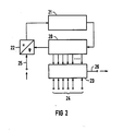
- the x-ray emitter has an electron gun 7 for generating the electron beam, which is a rotating beam that generates a focus of the desired size on the anode arc 3.
- a focusing arrangement 8 effects the focusing of the electron beam.
- the x-ray emitter 1, 3, 5, 7, 8 is supplied by a high voltage generator 9 with high and heating voltage.
- the focus rotating on the anode track 3 generates a fan-shaped, rotating X-ray beam which is faded in with the aid of an aperture 10 and which shines through a patient 11 lying on a couch 12 in the measurement opening 2 in different directions and after exiting the patient 11 a circular radiation detector 13, which consists of a series of detector elements. For this purpose, it runs at an angle to the axis A that deviates from 90 °.
- the measured values of the detector elements are fed via a data acquisition system 14 to a computer 15, which calculates the attenuation values of predetermined points of the examined layer of the patient 11 and effects their visual reproduction on an evaluation system 16.
- the mains voltage is on a line 17 and its frequency is evaluated by a synchronizing device 18 for the deflection system 6 and the data acquisition system 14 in such a way that the focus movement and the reading of the measured values relative to the previous revolution relative to the ripple period in each of the n revolutions of the focus the high voltage of the X-ray emitter, which is derived from the mains frequency, is slightly out of phase.
- This is the synchronization direction 18 and the computer 15 still assigned a control computer 19.
- the network frequency is generally different from the ripple frequency, which is a known, integral multiple of the network frequency.
- phase offset is chosen as p times the nth part of the ripple period.
- n is the number of focus revolutions used and p is any natural number.
- P is preferably chosen such that p and n are prime factors.
- r1 (fxt) denotes the ripple function supplied by the high-voltage generator 9 with the ripple frequency f and the time variable t.
- the target phase which is characterized by the natural numbers 1, p and n, is specified via the central control computer 15.
- the synchronizing device 18 provides the frequency f ', which is required for the electron beam guidance on the target circuit and the reading clock on the detector elements. All voltages and currents are subject to fluctuations with frequency f, which is marked in FIG. 1.
- FIG. 2 shows a block diagram of a possible synchronization device 18 with a frequency divider 20, an oscillator 21, a phase-voltage converter 22 and a comparator 23, at the input 24 of which there is information corresponding to the desired phase.
- the input of the phase-voltage converter 22, at which the mains frequency is located, is designated by 25 and the output by 26.
- the frequency divider 20 with the divider ratio 1024: 1 are selected as the mains frequency, as a result of which the oscillator frequency is fixed at 51.2 kHz.
- 60 Hz line frequency and other divider ratios are also conceivable.
- the synchronizer 18 provides the frequency f 'for the deflection generator 6 and the data acquisition system 14th
Abstract
Description
- Die Erfindung betrifft einen Computertomographen mit einem Röntgenstrahler mit kreisförmigem, eine Meßöffnung umschließendem Anodenbogen, auf dem der Fokus zur Durchstrahlung eines in der Meßöffnung liegenden Objektes mit einem fächerförmigen Röntgenstrahlenbündel unter verschiedenen Richtungen mit Hilfe eines Ablenksystems bewegt wird, sowie mit einem kreisförmigen Strahlendetektor, der aus einer Reihe von Detektorelementen besteht, deren Meßwerte über ein Datenerfassungssystem einem Rechner zugeführt werden, welcher die Schwächungswerte vorbestimmter Punkte der untersuchten Objektschicht berechnet und deren bildliche Wiedergabe bewirkt.
- Bei Computertomographen mit mechanisch bewegtem Röntgenstrahler zur Durchstrahlung des Objektes unter verschiedenen Richtungen ist zur Erzielung artefaktarmer Bilder des schlagenden Herzens die Sammlung der Meßwerte während mehrerer Herzzyklen erforderlich. Die Meßwerte werden dabei immer bei derselben Herzphase erzeugt. Zur Überwachung der unvermeidbaren Schwankungen der Hochspannung an dem Röntgenstrahler sind bei diesen Computertomographen Monitordetektoren mechanisch mit dem Röntgenstrahler verbunden, werden mit diesem also mitgeführt. Auf diese Weise ist es möglich, diese Schwankungen, die zu Änderungen der Meßwerte führen, rechnerisch zu berücksichtigen.
- Ein Computertomograph der eingangs genannten Art ist in US 4 352 021 beschrieben. Bei diesem Computertomographen ist eine sehr schnelle Bewegung des Fokus auf dem Anodenbogen möglich, so daß die Aufnahme von Herzbewegungsphasen während eines einzigen Herzzyklus möglich ist. Der Fokus eines Elektronenstrahles wird dabei mit Hilfe eines elektrischen und/oder magnetischen Ablenksystems über den kreisförmigen Anodenbogen geführt. Mechanische Teile zur Bewegung des Fokus sind demgemäß nicht mehr vorhanden. Deshalb ist auch die mechanische Mitführung von Monitordetektoren ausgeschlossen.
- Der Erfindung liegt die Aufgabe zugrunde, einen Computertomographen der eingangs genannten Art so auszubilden, daß Meßwertschwankungen, die von Schwankungen der Hochspannung des Röntgenstrahlers herrühren, nicht zu Bildartefakten führen.
- Diese Aufgabe ist erfindungsgemäß dadurch gelöst, daß das Ablenksystem und das Datenerfassungssystem derart synchronisiert sind, daß bei jedem der n Umläufe des Fokus die Fokusbewegung und das Auslesen der Meßwerte gegenüber dem vorausgegangenen Umlauf relativ zur Rippelperiode der Hochspannung des Röntgenstrahlers geringfügig phasenversetzt erfolgt.
- Bei der Erfindung ist davon ausgegangen, daß
- bei den zur Anwendung kommenden Hochspannungsgeneratoren die Schwankung der Hochspannung, der sogenannte Spannungsrippel, weitgehend periodisch erfolgt, wobei die Rippelfrequenz ein bekanntes Vielfaches der Netzfrequenz ist, und
- zur Erzielung rauscharmer Bilder der Fokus wiederholt den Anodenbogen überstreichen muß. - Dabei ist es gleichgültig, ob vor der Bildrekonstruktion homologe Meßdaten zusammengefaßt werden oder die zu den einzelnen Umläufen des Fokus gehörigen CT-Bilder superponiert werden.
- Die Erfindung ist nachfolgend anhand eines in der Zeichnung dargestellten Ausführungsbeispieles näher erläutert. Es zeigen:
- Fig. 1 einen Computertomographen nach der Erfindung, und
- Fig. 2 eine Einzelheit des Computertomographen gemäß Fig. 1.
- In der Fig. 1 ist ein Computertomograph mit einem Vakuumgefäß 1 eines Röntgenstrahlers dargestellt, in dem ein eine Meßöffnung 2 umschließender, kreisförmiger Anodenbogen 3 liegt. Der von einem Elektronenstrahl erzeugte Fokus auf dem Anodenbogen 3 beschreibt auf diesem eine Kreisbahn. Hierzu wird der Elektronenstrahl mit Hilfe eines gekrümmten Ablenkkondensators 4 und einer Ablenkanordnung 5, der ein Ablenkgenerator 6 zugeordnet ist, abgelenkt. Der Röntgenstrahler besitzt eine Elektronenkanone 7 für die Erzeugung des Elektronenstrahles, der ein, einen Fokus gewünschter Größe auf dem Anodenbogen 3 erzeugender, rotierender Strahl ist. Eine Fokussierungsanordnung 8 bewirkt die Fokussierung des Elektronenstrahles. Der Röntgenstrahler 1, 3, 5, 7, 8 wird von einem Hochspannungsgenerator 9 mit Hoch- und Heizspannung versorgt.
- Der auf der Anodenbahn 3 rotierende Fokus erzeugt ein mit Hilfe einer Blende 10 eingeblendetes, fächerförmiges, rotierendes Röntgenstrahlenbündel, das einen Patienten 11, der auf einer Liege 12 in der Meßöffnung 2 liegt, unter verschiedenen Richtungen durchstrahlt und nach dem Austritt aus dem Patienten 11 auf einem kreisförmigen Strahlendetektor 13, der aus einer Reihe von Detektorelementen besteht, auftrifft. Es verläuft hierzu unter einem von 90° abweichenden Winkel zur Achse A. Die Meßwerte der Detektorelemente werden über ein Datenerfassungssystem 14 einem Rechner 15 zugeführt, welcher die Schwächungswerte vorbestimmter Punkte der untersuchten Schicht des Patienten 11 berechnet und deren bildliche Wiedergabe auf einem Auswertesystem 16 bewirkt.
- Die Netzspannung liegt an einer Leitung 17 und deren Frequenz wird von einer Synchronisiereinrichtung 18 für das Ablenksystem 6 und das Datenerfassungssystem 14 in der Weise ausgewertet, daß bei jedem der n Umläufe des Fokus die Fokusbewegung und das Auslesen der Meßwerte gegenüber dem vorausgegangenen Umlauf relativ zur Rippelperiode der Hochspannung des Röntgenstrahlers, die von der Netzfrequenz abgeleitet ist, geringfügig phasenversetzt erfolgt. Hierzu ist der Synchronisierein richtung 18 und dem Rechner 15 noch ein Steuerrechner 19 zugeordnet. Die Netzfrequenz ist in der Regel von der Rippelfrequenz verschieden, welche ein bekanntes, ganzzahliges Vielfaches der Netzfrequenz ist.
- Der Phasenversatz wird als das p-fache des n-ten Teiles der Rippelperiode gewählt. Dabei bedeuten n die Anzahl der verwendeten Fokusumläufe und p eine beliebige natürliche Zahl. Vorzugsweise wird p so gewählt, daß p und n teilerfremd sind. Die Wirksamkeit der Methode ist wie folgt zu erkennen:
r1 (f x t) bezeichne die vom Hochspannungsgenerator 9 gelieferte Rippelfunktion mit der Rippelfrequenz f und der Zeitvariablen t. - Die Fourier-Entwicklung lautet:

Δ t = p/(n x f)
verteilte Abtastpunkte ergibt sich die reduzierte Rippelfunktion rn (ft) zu
- Es werden die Umlaufzeit tu des Fokus, die Anzahl n der Umläufe und die natürliche Zahl p so gewählt, daß
tu = (1 + p/n)tr
mit einer geeigneten natürlichen Zahl 1 gilt.
Hierzu ein Beispiel:
Für einen Niederfrequenz-Hochspannungsgenerator 9 kann z.B. tr = 10 ms sein. Wählt man 1 = 5 und p = 1 und n zwischen 10 und 20, so folgt
tu = (5 + 1/n)tr ≈ 50 ms.
Die Bedingung
tu = (1 + p/n) tr
kann durch Frequenzsynchronisation eingehalten werden. Mit f′ = 1/tu als Umlauffrequenz ist zu setzen
f′ = f/(1 + p/n). Über den zentralen Steuerrechner 15 wird die Sollphase vorgegeben, die durch die natürlichen Zahlen 1, p und n charakterisiert ist. Die Synchronisiervorrichtung 18 liefert die Frequenz f′, die für die Elektronenstrahlführung auf dem Sollkreis und den Auslesetakt an den Detektorelementen benötigt wird. Alle Spannungen und Ströme sind Schwankungen mit der Frequenz f unterworfen, was in Fig. 1 markiert ist. - Die Fig. 2 zeigt ein Blockschaltbild einer möglichen Synchronisiervorrichtung 18 mit einem Frequenzteiler 20, einem Oszillator 21, einem Phasen-Spannungswandler 22 und einem Komparator 23, an dessen Eingang 24 eine der Sollphase entsprechende Information liegt. Der Eingang des Phasen-Spannungswandlers 22, an dem die Netzfrequenz liegt, ist mit 25 und der Ausgang mit 26 bezeichnet.
- Im vorliegenden Beispiel ist als Netzfrequenz 50 Hz und der Frequenzteiler 20 mit dem Teilerverhältnis 1024 : 1 gewählt, wodurch die Oszillatorfrequenz zu 51.2 kHz festliegt. Es sind aber auch 60 Hz Netzfrequenz und andere Teilerverhältnisse denkbar. Die Synchronisiervorrichtung 18 liefert die Frequenz f′ für den Ablenkgenerator 6 und das Datenerfassungssysten 14.
Claims (3)
Priority Applications (4)
| Application Number | Priority Date | Filing Date | Title |
|---|---|---|---|
| DE8888119417T DE3882372D1 (en) | 1988-11-22 | 1988-11-22 | Computer-tomograph. |
| EP88119417A EP0370124B1 (de) | 1988-11-22 | 1988-11-22 | Computer-Tomograph |
| US07/430,369 US4962513A (en) | 1988-11-22 | 1989-11-02 | Computer tomography apparatus which avoids image artifacts caused by periodical voltage variations |
| JP1989134811U JPH0725922Y2 (ja) | 1988-11-22 | 1989-11-20 | コンピユータトモグラフ |
Applications Claiming Priority (1)
| Application Number | Priority Date | Filing Date | Title |
|---|---|---|---|
| EP88119417A EP0370124B1 (de) | 1988-11-22 | 1988-11-22 | Computer-Tomograph |
Publications (2)
| Publication Number | Publication Date |
|---|---|
| EP0370124A1 true EP0370124A1 (de) | 1990-05-30 |
| EP0370124B1 EP0370124B1 (de) | 1993-07-14 |
Family
ID=8199593
Family Applications (1)
| Application Number | Title | Priority Date | Filing Date |
|---|---|---|---|
| EP88119417A Expired - Lifetime EP0370124B1 (de) | 1988-11-22 | 1988-11-22 | Computer-Tomograph |
Country Status (4)
| Country | Link |
|---|---|
| US (1) | US4962513A (de) |
| EP (1) | EP0370124B1 (de) |
| JP (1) | JPH0725922Y2 (de) |
| DE (1) | DE3882372D1 (de) |
Cited By (2)
| Publication number | Priority date | Publication date | Assignee | Title |
|---|---|---|---|---|
| DE4139150C1 (en) * | 1991-11-28 | 1993-06-24 | Siemens Ag, 8000 Muenchen, De | Computer tomograph with part ring formed X=ray source and detector - has double ring system without complementary interpolation |
| WO2000065333A1 (en) * | 1999-04-27 | 2000-11-02 | Quanta Vision, Inc. | Device for reduced-angle x-ray tomography |
Families Citing this family (7)
| Publication number | Priority date | Publication date | Assignee | Title |
|---|---|---|---|---|
| US5452720A (en) * | 1990-09-05 | 1995-09-26 | Photoelectron Corporation | Method for treating brain tumors |
| US6234671B1 (en) * | 1998-10-06 | 2001-05-22 | Cardiac Mariners, Inc. | X-ray system with scanning beam x-ray source below object table |
| US6198802B1 (en) * | 1998-10-06 | 2001-03-06 | Cardiac Mariners, Inc. | Scanning beam x-ray source and assembly |
| DE10240628B4 (de) * | 2002-09-03 | 2012-06-21 | Siemens Ag | Röntgenröhre mit Ringanode und Röntgen-System mit einer solchen Röntgenröhre |
| DE102012005767A1 (de) * | 2012-03-25 | 2013-09-26 | DüRR DENTAL AG | Phasenkontrast-Röntgen-Tomographiegerät |
| DE102013206252A1 (de) * | 2013-04-09 | 2014-10-09 | Helmholtz-Zentrum Dresden - Rossendorf E.V. | Anordnung zur schnellen Elektronenstrahl-Röntgencomputertomographie |
| CN110840477B (zh) * | 2019-11-25 | 2023-07-18 | 上海联影医疗科技股份有限公司 | 扫描方法、装置、计算机设备和计算机可读存储介质 |
Citations (2)
| Publication number | Priority date | Publication date | Assignee | Title |
|---|---|---|---|---|
| DE2811464A1 (de) * | 1977-03-17 | 1978-09-21 | Jacob Haimson | Verfahren und vorrichtung zum erzeugen von roentgenstrahlen aus verschiedenen richtungen ohne sich bewegende teile |
| EP0282870A1 (de) * | 1987-03-20 | 1988-09-21 | Siemens Aktiengesellschaft | Computertomograph |
Family Cites Families (7)
| Publication number | Priority date | Publication date | Assignee | Title |
|---|---|---|---|---|
| US4041315A (en) * | 1972-05-17 | 1977-08-09 | E M I Limited | Computerized tomography comprising laterally shifting detected beams within a rotated fan of radiation |
| US4130759A (en) * | 1977-03-17 | 1978-12-19 | Haimson Research Corporation | Method and apparatus incorporating no moving parts, for producing and selectively directing x-rays to different points on an object |
| US4352021A (en) * | 1980-01-07 | 1982-09-28 | The Regents Of The University Of California | X-Ray transmission scanning system and method and electron beam X-ray scan tube for use therewith |
| JPS57168645A (en) * | 1981-04-10 | 1982-10-18 | Hitachi Medical Corp | Radioactive ray image photographing apparatus |
| US4597094A (en) * | 1983-12-01 | 1986-06-24 | Bennett X-Ray Corp. | Automated setting of technic factors for x-ray examinations with a ranging transducer moving in and out of the x-ray beam path |
| JPS61209641A (ja) * | 1985-03-15 | 1986-09-17 | 株式会社東芝 | X線ct装置 |
| US4916718A (en) * | 1988-11-23 | 1990-04-10 | Picker International, Inc. | Precision scan position resolver for CT scanners |
-
1988
- 1988-11-22 DE DE8888119417T patent/DE3882372D1/de not_active Expired - Fee Related
- 1988-11-22 EP EP88119417A patent/EP0370124B1/de not_active Expired - Lifetime
-
1989
- 1989-11-02 US US07/430,369 patent/US4962513A/en not_active Expired - Fee Related
- 1989-11-20 JP JP1989134811U patent/JPH0725922Y2/ja not_active Expired - Lifetime
Patent Citations (2)
| Publication number | Priority date | Publication date | Assignee | Title |
|---|---|---|---|---|
| DE2811464A1 (de) * | 1977-03-17 | 1978-09-21 | Jacob Haimson | Verfahren und vorrichtung zum erzeugen von roentgenstrahlen aus verschiedenen richtungen ohne sich bewegende teile |
| EP0282870A1 (de) * | 1987-03-20 | 1988-09-21 | Siemens Aktiengesellschaft | Computertomograph |
Non-Patent Citations (1)
| Title |
|---|
| APPLIED OPTICS * |
Cited By (2)
| Publication number | Priority date | Publication date | Assignee | Title |
|---|---|---|---|---|
| DE4139150C1 (en) * | 1991-11-28 | 1993-06-24 | Siemens Ag, 8000 Muenchen, De | Computer tomograph with part ring formed X=ray source and detector - has double ring system without complementary interpolation |
| WO2000065333A1 (en) * | 1999-04-27 | 2000-11-02 | Quanta Vision, Inc. | Device for reduced-angle x-ray tomography |
Also Published As
| Publication number | Publication date |
|---|---|
| JPH0274010U (de) | 1990-06-06 |
| JPH0725922Y2 (ja) | 1995-06-14 |
| DE3882372D1 (en) | 1993-08-19 |
| EP0370124B1 (de) | 1993-07-14 |
| US4962513A (en) | 1990-10-09 |
Similar Documents
| Publication | Publication Date | Title |
|---|---|---|
| DE19957082B4 (de) | Verfahren zur Untersuchung eines eine periodische Bewegung ausführenden Körperbereichs | |
| DE19957083B4 (de) | Verfahren zur Untersuchung eines eine periodische Bewegung ausführenden Körperbereichs | |
| DE69838533T2 (de) | Verfahren und Gerät für Strahlungstomographie | |
| DE19622075C2 (de) | Verfahren und Gerät zur radiologischen Untersuchung von Herzphasen eines Patienten | |
| DE60133260T2 (de) | Verfahren und Gerät für strahlentomographische Bilderzeugung | |
| DE19802405B4 (de) | Röntgendiagnostikeinrichtung mit einem Computertomographen | |
| EP0364613B1 (de) | Verfahrenzum Betrieb eines Computertomographen | |
| DE102007008118A1 (de) | Verfahren zur Erzeugung tomographischer Darstellungen mit einem Röntgen-Computertomographie-System mit Streustrahlungskorrektur | |
| EP0370124B1 (de) | Computer-Tomograph | |
| DE3325939A1 (de) | Computer-tomograph | |
| DE102016207437A1 (de) | Spektralunabhängige Ermittlung von Kalkablagerungen in Blutgefäßen | |
| DE19633359C2 (de) | Zweiebenen-Röntgendiagnostikanlage | |
| DE19800946A1 (de) | Volumen-Computertomographiesystem | |
| DE3244636C2 (de) | ||
| EP0026494A1 (de) | Röntgenschichtgerät zur Herstellung von Transversalschichtbildern | |
| DE102010042683A1 (de) | Einrichtung und Verfahren zur Erzeugung von Röntgenstrahlung sowie Rechenprogramm und Datenträger | |
| DE2745390C2 (de) | Röntgensichtgerät für die Herstellung von Transversalschichtbildern | |
| EP0028014A1 (de) | Schichtgerät zur Herstellung von Transversalschichtbildern | |
| DE3304213A1 (de) | Roentgendiagnostikanlage mit mitteln zur unterdrueckung der streustrahlung | |
| EP0367856A1 (de) | Computer-Tomograph | |
| DE2716818C2 (de) | ||
| DE2737566A1 (de) | Medizinisches geraet zur untersuchung eines koerpers mittels durchdringender strahlung | |
| DE102007050889A1 (de) | Verfahren und Tomographiegerät zur Erzeugung tomographischer Bilder zu unterschiedlichen Bewegungsphasen eines sich periodisch bewegenden Organs eines Patienten | |
| EP0276437B1 (de) | Röntgenstrahlenquelle | |
| Thomlinson | Transvenous coronary angiography in humans |
Legal Events
| Date | Code | Title | Description |
|---|---|---|---|
| PUAI | Public reference made under article 153(3) epc to a published international application that has entered the european phase |
Free format text: ORIGINAL CODE: 0009012 |
|
| AK | Designated contracting states |
Kind code of ref document: A1 Designated state(s): DE FR GB |
|
| 17P | Request for examination filed |
Effective date: 19900625 |
|
| 17Q | First examination report despatched |
Effective date: 19921215 |
|
| GRAA | (expected) grant |
Free format text: ORIGINAL CODE: 0009210 |
|
| AK | Designated contracting states |
Kind code of ref document: B1 Designated state(s): DE FR GB |
|
| PG25 | Lapsed in a contracting state [announced via postgrant information from national office to epo] |
Ref country code: GB Effective date: 19930714 Ref country code: FR Effective date: 19930714 |
|
| REF | Corresponds to: |
Ref document number: 3882372 Country of ref document: DE Date of ref document: 19930819 |
|
| EN | Fr: translation not filed | ||
| GBV | Gb: ep patent (uk) treated as always having been void in accordance with gb section 77(7)/1977 [no translation filed] |
Effective date: 19930714 |
|
| PLBE | No opposition filed within time limit |
Free format text: ORIGINAL CODE: 0009261 |
|
| STAA | Information on the status of an ep patent application or granted ep patent |
Free format text: STATUS: NO OPPOSITION FILED WITHIN TIME LIMIT |
|
| 26N | No opposition filed | ||
| PGFP | Annual fee paid to national office [announced via postgrant information from national office to epo] |
Ref country code: DE Payment date: 19950119 Year of fee payment: 7 |
|
| PG25 | Lapsed in a contracting state [announced via postgrant information from national office to epo] |
Ref country code: DE Effective date: 19960801 |