EP0372828A2 - Microwave connector - Google Patents
Microwave connector Download PDFInfo
- Publication number
- EP0372828A2 EP0372828A2 EP89312474A EP89312474A EP0372828A2 EP 0372828 A2 EP0372828 A2 EP 0372828A2 EP 89312474 A EP89312474 A EP 89312474A EP 89312474 A EP89312474 A EP 89312474A EP 0372828 A2 EP0372828 A2 EP 0372828A2
- Authority
- EP
- European Patent Office
- Prior art keywords
- shield
- contact ring
- outer conductor
- connector
- conductor
- Prior art date
- Legal status (The legal status is an assumption and is not a legal conclusion. Google has not performed a legal analysis and makes no representation as to the accuracy of the status listed.)
- Withdrawn
Links
Images


Classifications
-
- H—ELECTRICITY
- H01—ELECTRIC ELEMENTS
- H01R—ELECTRICALLY-CONDUCTIVE CONNECTIONS; STRUCTURAL ASSOCIATIONS OF A PLURALITY OF MUTUALLY-INSULATED ELECTRICAL CONNECTING ELEMENTS; COUPLING DEVICES; CURRENT COLLECTORS
- H01R9/00—Structural associations of a plurality of mutually-insulated electrical connecting elements, e.g. terminal strips or terminal blocks; Terminals or binding posts mounted upon a base or in a case; Bases therefor
- H01R9/03—Connectors arranged to contact a plurality of the conductors of a multiconductor cable, e.g. tapping connections
- H01R9/05—Connectors arranged to contact a plurality of the conductors of a multiconductor cable, e.g. tapping connections for coaxial cables
- H01R9/0521—Connection to outer conductor by action of a nut
Definitions
- the present invention is directed to a connector for microwave transmission lines which provides improved mechanical stability and cable-to-connector retention strength while not significantly altering the electrical path of the transmission line.
- Microwave transmission lines themselves are well known and often take the form of a flexible or semirigid coaxial cable. Such cables are typically provided with a connector at at least one end of the cable for connecting the cable to a source of microwave energy or to a load.
- Connectors for microwave transmission lines in the form of coaxial cables are disclosed in, for example, U.S. Patents 3,778,535 and 4,545,637.
- Connectors for coaxial cables for non-microwave uses are disclosed in Patents 3,275,737, 4,053,200 and 4,156,554.
- the connector must present a constant characteristic impedance, must have controlled compensation of electrical discontinuities resulting from unavoidable dimensional changes, must meet close mechanical dimensional tolerances ( ⁇ 0.001 inch), and must not introduce reflections in the microwave transmission line. It is also desirable that the connector provide high cable-to-connector retention strength, so that the connector does not introduce a weak mechanical link in the microwave transmission line. The connector must further provide electrical continuity with minimum ohmic losses and protect the transmission line from environmental effects.
- the present invention provides a connector for microwave transmission lines which meets all of the characteristics required of a microwave connector and, in addition, provides excellent cable-to-connector retention strength without significantly altering the electrical path of the transmission line.
- the present invention provides a cable-to-connector retention strength on the order of 100% of the tensile strength of the coaxial cable to which the connector is attached, in contrast to prior connectors which offer cable-to-connector retention strengths only about half as great.
- the present invention is a connector for microwave transmission lines which have an inner conductor, a low-density polytetrafluoroethylene dielectric layer surrounding the inner conductor, a thin outer conductor surrounding the dielectric layer, a woven wire braid shield surrounding the thin outer conductor and an exterior insulating covering surrounding the shield.
- the connector comprises a contact ring surrounding and in physical and electrical contact on an interior surface of the ring with the outer conductor. A first end of the contact ring, the outer conductor and the dielectric layer all terminate in a common plane.
- the contact ring has a second end spaced from the first end of the contact ring.
- the contact ring has a shouldered portion between the first and second ends thereof for contacting the shield and causing the shield to terminate in a plane parallel to and spaced apart from the common plane of the first end of the contact ring, the thin outer conductor and the dielectric layer.
- a clamp nut movably surrounds the shield and contact ring along at least a portion thereof, and a connector shell is provided which is removably engageable with the clamp nut and surrounds at least the shouldered portion of the contact ring.
- the connector shell has an extending portion adapted to receive a coupling nut.
- the outer conductor, the contact ring, the shield, the clamp nut and the connector shell are all in physical contact to provide an electrical path from the thin outer conductor to the connector shell while keeping a constant characteristic cable impedance.
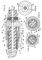
- Connector 12 includes a coupling nut 14, shown exploded from connector 12 in Figure 1, which is rotatably attached to connector 12 to enable connector 12 to be attached to a source of microwave energy or to a load.
- Coupling nut 14 may be optionally configured as either male or female to mate with a corresponding female or male, respectively, connector on the source or load.
- Coupling nut 14 may thus be any desired configuration suitable for attaching cable 10 to a source or load, and the particular configuration of coupling nut 14 is not critical to the invention.
- Connector 12 comprises a contact ring 16, a clamp nut 18 and a connector shell 20, shown exploded from clamp nut 18 in Figure 2.
- Connector 12 is best understood by reference to Figures 3-6.
- cable 10 comprises, viewed from the inside out, an inner conductor 22, a dielectric layer 24 concentrically surrounding inner conductor 22, a thin outer conductor 26 concentrically surrounding the dielectric layer 24, a woven wire braid shield 28 concentrically surrounding the thin outer conductor 26, and an exterior insulating covering 30 concentrically surrounding the shield and forming an outer jacket for cable 10.
- Outer conductor 26 is preferably, but not necessarily, in the form of a thin conductive ribbon wound spirally with about 40% overlap around dielectric layer 24.
- inner conductor 22 and thin outer conductor 26 form the primary electrical path for microwave energy being carried by cable 10.
- the center conductor is considered to be the "signal" conductor and the thin outer conductor is considered to be the return, or ground, and acts as an RF (radio frequency) shield.
- Wire braid 28 is not the RF shield, but acts only as a backup for the thin outer conductor.
- Contact ring 16 is provided with a central bore and concentrically surrounds thin outer conductor 26.
- the interior surface of the bore in contact ring 16 is in close physical and electrical contact with outer conductor 26 and permits a near-perfect transmission line to be maintained in the area of contact between the outer conductor 26 and the interior surface of the bore in contact ring 16.
- a first end 32 of contact ring 16 abuts an interior shoulder 34 on connector shell 20.
- connector shell 20 has a larger diameter interior bore to surround contact ring 16 and clamp nut 18, and a reduced diameter bore 36. Shoulder 34 is formed between the larger diameter bore and reduced diameter bore 36.
- Thin outer conductor 26 also abuts shoulder 34 of connector shell 20.
- first end 32 of contact ring 16, outer conductor 26 and dielectric layer 24 all terminate in a common plane defined by shoulder 34.
- An end 38 of inner conductor 22 projects beyond the common plane defined by shoulder 34 of connector shell 20.
- End 38 of inner conductor 32 is received in a pin 40.
- Pin 40 is substantially coaxial with inner conductor 22 and extends within reduced bore 36 and beyond the end of connector shell 20.
- a dielectric plug 44 concentrically surrounds pin 40 and supports pin 40 while insulating it from connector shell 20.
- dielectric layer 24 may be any suitable dielectric, it has been observed that the loss characteristics of the cable are improved when the dielectric layer 24 is made of an extruded low-density polytetrafluoroethylene (PTFE), also known by its trademark “TEFLON.”
- PTFE polytetrafluoroethylene
- the dielectric constant of solid PTFE ranges from 2.0 to 2.1; "low density" PTFE is defined as having a specific gravity less than 2.0.
- the loss tangent for a cable made with solid PTFE for instance, has been observed to be .0002; for low-density PTFE, .000064.
- low-density PTFE is very desirable for its electrical properties.
- low-density PTFE does not have the mechanical rigidity of solid PTFE. It has been found that when low-density PTFE is used as a dielectric, flexing forces on pin 40, due to engaging and disengaging connector 12, will cause pin 40 to recede into the cable or pull out from the cable.
- pin 40 and plug 44 are retained in place, or "captivated", by epoxy 45 in known manner.
- Epoxy 45 engages two oppositely-facing shoulders created by a reduced diameter portion of pin 40.
- a second end 46 of contact ring 16 extends for a distance between outer conductor 26 and wire braid shield 28 so that shield 28 surrounds the second end 46 of contact ring 16.
- Shield 28 is preferably joined to second end 46 by soldering, such as at 48.
- Contact ring 16 is provided with a shoulder 50 against which the end of shield 28 abuts. Shoulder 50 defines a plane parallel to the plane of shoulder 34 on connector shell 20 and spaced apart from it.
- shield 28 does not terminate in the plane of the first end 32 of contact ring 16 and the ends of outer conductor 26 and dielectric layer 24, but terminates a distance behind it.
- Clamp nut 18 movably surrounds a portion of cable 10 and is in physical and electrical contact with at least that portion of shield 28 which surrounds the second end 46 of contact ring 16. Clamp nut 18 is free to rotate with respect to cable 10 and has an externally threaded portion 52 which engages an internally threaded portion 54 of the larger-diameter bore in connector shell 20. When connector shell 20 is threadably engaged with clamp nut 18, there is a direct electrical path from outer conductor 26 to connector shell 20.
- Second end 46 of contact ring 16 is provided with a slight chamfer 56 to allow a smooth transition of shield 28 over second end 46.
- Second end 46 of contact ring 16 provides improved mechanical stability to connector 12 while not disturbing the electrical path of the transmission line. That is, uniform spacing between inner conductor 22 and outer conductor 26 is maintained in the contact area.
- second end 46 of contact ring 16 between the outer conductor 26 and wire shield 28, more surface area of the wire braid 28 can be soldered to second end 46, providing superior mechanical stability between the outer conductor 26 and wire braid 28. The result is a mechanical robustness not found in prior connectors.
- the present invention allows for a connector-to-cable retention force of at least 100% of the cable tensile strength, as compared to only 50% in prior connectors. Moreover, terminating wire braid 28 behind the plane of the first end of the contact ring, outer conductor 26 and dielectric layer 24 facilitates machining the end of cable 10 to a smooth surface. With the structure of the present invention, the possibility of the braid wires of shield 28 "smearing" over dielectric layer 24 and the resultant likelihood of voids being created between the braid wire is eliminated. This results in a connector with highly consistent electrical characteristics.
- FIG. 7 A slightly different embodiment of the connector of the present invention is illustrated in Figure 7.
- the embodiment shown in Figure 7 is the same as the embodiment already described, with the exception of the dielectric plug in connector shell 20 and the pin contact.
- conductor 22 terminates in the common plane of conductor 26, dielectric layer 24 and first end 32 of contact ring 16, and is provided with a socket 58 to receive a shouldered projection 60 on pin contact 62.
- Projection 60 is preferably soldered in place in socket 58.
- projection 60 has a slight shoulder 64 which abuts the end of center conductor 22.
- Dielectric plug 44 surrounds and supports pin 62 and abuts dielectric layer 24 of cable 10. In this embodiment there is only a single step, at shoulder 64, from the diameter of conductor 22 to the diameter of pin 62, which allows connector 12 to even more closely approach a reflectionless termination.
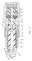
- FIG. 8 shows another arrangement of the concentric layers around the conductor 22. It has been found that the loss characteristics through the connector are improved when the shielding braid 28 around the outer conductor 26 terminates at a distance from the plane at which the outer conductor 26 and the dielectric 24 terminate.
- contact ring 72 fits into clamp nut 18, as with the previous embodiments.
- contact ring 72 is provided with an axial bore having three different diameter portions on the interior surface of the bore. In the first portion, the diameter of the bore is large enough to receive the entire diameter of cable 10. The next diameter portion is large enough to receive only that part of the cable including wire braid 28 but excluding outer jacket 30. These two diameter portions define an interior shoulder 72a, against which jacket 30 abuts.
- the last diameter portion is only large enough to receive the part of the cable comprising center conductor 22, dielectric 24 and outer conductor 26.
- the second and last diameter portions define a second shoulder, 72b, against which braid 28 abuts. Shoulder 72b ensures that braid 28 will terminate a distance from the common plane of center conductor 22, dielectric 24 and outer conductor 26, while allowing the radial distance between center conductor 22 and outer conductor 26 to remain constant all the way to the common plane.
- Figure 8 also shows another "captivation" technique, which may be used with the embodiments of Figures 3 or 7 as well.
- pin 80 is soldered through opening 82 to the conductor 22.
- Pin 80 is shaped with a reduced diameter section to form two opposite facing shoulders which are embedded in captivating assembly 74, 76, 78. The shoulders of pin 80 are held by epoxy 74, which thus prevents any axial motion of pin 80 or conductor 22 relative to the connector.
Abstract
Description
- The present invention is directed to a connector for microwave transmission lines which provides improved mechanical stability and cable-to-connector retention strength while not significantly altering the electrical path of the transmission line.
- Microwave transmission lines themselves are well known and often take the form of a flexible or semirigid coaxial cable. Such cables are typically provided with a connector at at least one end of the cable for connecting the cable to a source of microwave energy or to a load. Connectors for microwave transmission lines in the form of coaxial cables are disclosed in, for example, U.S. Patents 3,778,535 and 4,545,637. Connectors for coaxial cables for non-microwave uses are disclosed in Patents 3,275,737, 4,053,200 and 4,156,554.
- It is also known that there are several important requirements that a microwave connector must satisfy. The connector must present a constant characteristic impedance, must have controlled compensation of electrical discontinuities resulting from unavoidable dimensional changes, must meet close mechanical dimensional tolerances (± 0.001 inch), and must not introduce reflections in the microwave transmission line. It is also desirable that the connector provide high cable-to-connector retention strength, so that the connector does not introduce a weak mechanical link in the microwave transmission line. The connector must further provide electrical continuity with minimum ohmic losses and protect the transmission line from environmental effects.
- The present invention provides a connector for microwave transmission lines which meets all of the characteristics required of a microwave connector and, in addition, provides excellent cable-to-connector retention strength without significantly altering the electrical path of the transmission line. The present invention provides a cable-to-connector retention strength on the order of 100% of the tensile strength of the coaxial cable to which the connector is attached, in contrast to prior connectors which offer cable-to-connector retention strengths only about half as great.
- The present invention is a connector for microwave transmission lines which have an inner conductor, a low-density polytetrafluoroethylene dielectric layer surrounding the inner conductor, a thin outer conductor surrounding the dielectric layer, a woven wire braid shield surrounding the thin outer conductor and an exterior insulating covering surrounding the shield. The connector comprises a contact ring surrounding and in physical and electrical contact on an interior surface of the ring with the outer conductor. A first end of the contact ring, the outer conductor and the dielectric layer all terminate in a common plane. The contact ring has a second end spaced from the first end of the contact ring. The contact ring has a shouldered portion between the first and second ends thereof for contacting the shield and causing the shield to terminate in a plane parallel to and spaced apart from the common plane of the first end of the contact ring, the thin outer conductor and the dielectric layer. A clamp nut movably surrounds the shield and contact ring along at least a portion thereof, and a connector shell is provided which is removably engageable with the clamp nut and surrounds at least the shouldered portion of the contact ring. The connector shell has an extending portion adapted to receive a coupling nut. The outer conductor, the contact ring, the shield, the clamp nut and the connector shell are all in physical contact to provide an electrical path from the thin outer conductor to the connector shell while keeping a constant characteristic cable impedance.
- For the purpose of illustrating the invention, there is shown in the drawings a form which is presently preferred; it being understood, however, that this invention is not limited to the precise arrangements and instrumentalities shown.
- Figure 1 illustrates in simplified form a microwave transmission line in the form of a coaxial cable fitted at each end with connectors according to the present invention.
- Figure 2 is a partially-exploded view of a connector according to the present invention showing the connector shell removed from the clamp nut.
- Figure 3 is a longitudinal sectional view of a portion of the cable and the connector taken along the lines 3-3 of Figure 1.
- Figures 4, 5 and 6 are transverse sectional views of the cable and connector taken along the lines 4-4, 5-5 and 6-6, respectively, of Figure 3.
- Figure 7 is a longitudinal sectional view of a portion of a microwave transmission line in the form of a coaxial cable fitted at one end with a connector according to an alternate embodiment of the present invention.
- Figure 8 is a longitudinal sectional view of a portion of a microwave transmission line in the form of a coaxial cable fitted at one end with a connector according to a third embodiment of the present invention.
- Referring now to the drawings, wherein like numerals indicate like elements, there is shown a microwave transmission line in the form of a
coaxial cable 10 fitted at each end with aconnector 12 according to the present invention.Connector 12 includes acoupling nut 14, shown exploded fromconnector 12 in Figure 1, which is rotatably attached toconnector 12 to enableconnector 12 to be attached to a source of microwave energy or to a load.Coupling nut 14 may be optionally configured as either male or female to mate with a corresponding female or male, respectively, connector on the source or load.Coupling nut 14 may thus be any desired configuration suitable for attachingcable 10 to a source or load, and the particular configuration ofcoupling nut 14 is not critical to the invention. - The major elements of
connector 12 are shown in Figure 2.Connector 12 comprises acontact ring 16, aclamp nut 18 and aconnector shell 20, shown exploded fromclamp nut 18 in Figure 2. -
Connector 12 is best understood by reference to Figures 3-6. As shown in those figures,cable 10 comprises, viewed from the inside out, aninner conductor 22, adielectric layer 24 concentrically surroundinginner conductor 22, a thinouter conductor 26 concentrically surrounding thedielectric layer 24, a wovenwire braid shield 28 concentrically surrounding the thinouter conductor 26, and an exterior insulating covering 30 concentrically surrounding the shield and forming an outer jacket forcable 10. -
Outer conductor 26 is preferably, but not necessarily, in the form of a thin conductive ribbon wound spirally with about 40% overlap arounddielectric layer 24. - As those skilled in the art will understand,
inner conductor 22 and thinouter conductor 26 form the primary electrical path for microwave energy being carried bycable 10. Typically, the center conductor is considered to be the "signal" conductor and the thin outer conductor is considered to be the return, or ground, and acts as an RF (radio frequency) shield.Wire braid 28 is not the RF shield, but acts only as a backup for the thin outer conductor. - Contact
ring 16 is provided with a central bore and concentrically surrounds thinouter conductor 26. The interior surface of the bore incontact ring 16 is in close physical and electrical contact withouter conductor 26 and permits a near-perfect transmission line to be maintained in the area of contact between theouter conductor 26 and the interior surface of the bore incontact ring 16. Afirst end 32 ofcontact ring 16 abuts aninterior shoulder 34 onconnector shell 20. As can be seen from the figures,connector shell 20 has a larger diameter interior bore to surroundcontact ring 16 andclamp nut 18, and a reduceddiameter bore 36.Shoulder 34 is formed between the larger diameter bore and reduceddiameter bore 36. Thinouter conductor 26 also abutsshoulder 34 ofconnector shell 20. Thus,first end 32 ofcontact ring 16,outer conductor 26 anddielectric layer 24 all terminate in a common plane defined byshoulder 34. Anend 38 ofinner conductor 22 projects beyond the common plane defined byshoulder 34 ofconnector shell 20.End 38 ofinner conductor 32 is received in apin 40.Pin 40 is substantially coaxial withinner conductor 22 and extends within reducedbore 36 and beyond the end ofconnector shell 20. Adielectric plug 44 concentrically surroundspin 40 and supportspin 40 while insulating it fromconnector shell 20. - Although
dielectric layer 24 may be any suitable dielectric, it has been observed that the loss characteristics of the cable are improved when thedielectric layer 24 is made of an extruded low-density polytetrafluoroethylene (PTFE), also known by its trademark "TEFLON." The dielectric constant of solid PTFE ranges from 2.0 to 2.1; "low density" PTFE is defined as having a specific gravity less than 2.0. The loss tangent for a cable made with solid PTFE, for instance, has been observed to be .0002; for low-density PTFE, .000064. Clearly, low-density PTFE is very desirable for its electrical properties. However, low-density PTFE does not have the mechanical rigidity of solid PTFE. It has been found that when low-density PTFE is used as a dielectric, flexing forces onpin 40, due to engaging and disengagingconnector 12, will causepin 40 to recede into the cable or pull out from the cable. - To prevent this axial motion of
pin 40 orcenter conductor 22,pin 40 andplug 44 are retained in place, or "captivated", byepoxy 45 in known manner. Epoxy 45 engages two oppositely-facing shoulders created by a reduced diameter portion ofpin 40. - In the embodiments shown in Figures 3-7, a
second end 46 ofcontact ring 16 extends for a distance betweenouter conductor 26 andwire braid shield 28 so thatshield 28 surrounds thesecond end 46 ofcontact ring 16. Shield 28 is preferably joined tosecond end 46 by soldering, such as at 48. Contactring 16 is provided with ashoulder 50 against which the end ofshield 28 abuts.Shoulder 50 defines a plane parallel to the plane ofshoulder 34 onconnector shell 20 and spaced apart from it. Thus, shield 28 does not terminate in the plane of thefirst end 32 ofcontact ring 16 and the ends ofouter conductor 26 anddielectric layer 24, but terminates a distance behind it. -
Clamp nut 18 movably surrounds a portion ofcable 10 and is in physical and electrical contact with at least that portion ofshield 28 which surrounds thesecond end 46 ofcontact ring 16.Clamp nut 18 is free to rotate with respect tocable 10 and has an externally threadedportion 52 which engages an internally threadedportion 54 of the larger-diameter bore inconnector shell 20. Whenconnector shell 20 is threadably engaged withclamp nut 18, there is a direct electrical path fromouter conductor 26 toconnector shell 20. -
Second end 46 ofcontact ring 16 is provided with aslight chamfer 56 to allow a smooth transition ofshield 28 oversecond end 46.Second end 46 ofcontact ring 16 provides improved mechanical stability toconnector 12 while not disturbing the electrical path of the transmission line. That is, uniform spacing betweeninner conductor 22 andouter conductor 26 is maintained in the contact area. In addition, by placing thesecond end 46 ofcontact ring 16 between theouter conductor 26 andwire shield 28, more surface area of thewire braid 28 can be soldered tosecond end 46, providing superior mechanical stability between theouter conductor 26 andwire braid 28. The result is a mechanical robustness not found in prior connectors. The present invention allows for a connector-to-cable retention force of at least 100% of the cable tensile strength, as compared to only 50% in prior connectors. Moreover, terminatingwire braid 28 behind the plane of the first end of the contact ring,outer conductor 26 anddielectric layer 24 facilitates machining the end ofcable 10 to a smooth surface. With the structure of the present invention, the possibility of the braid wires ofshield 28 "smearing" overdielectric layer 24 and the resultant likelihood of voids being created between the braid wire is eliminated. This results in a connector with highly consistent electrical characteristics. - A slightly different embodiment of the connector of the present invention is illustrated in Figure 7. The embodiment shown in Figure 7 is the same as the embodiment already described, with the exception of the dielectric plug in
connector shell 20 and the pin contact. Instead of the contact receiving an extending end of thecenter conductor 22,conductor 22 terminates in the common plane ofconductor 26,dielectric layer 24 andfirst end 32 ofcontact ring 16, and is provided with asocket 58 to receive a shoulderedprojection 60 onpin contact 62.Projection 60 is preferably soldered in place insocket 58. As seen in Figure 7,projection 60 has aslight shoulder 64 which abuts the end ofcenter conductor 22.Dielectric plug 44 surrounds and supportspin 62 and abutsdielectric layer 24 ofcable 10. In this embodiment there is only a single step, atshoulder 64, from the diameter ofconductor 22 to the diameter ofpin 62, which allowsconnector 12 to even more closely approach a reflectionless termination. - The embodiment shown in Figure 8 shows another arrangement of the concentric layers around the
conductor 22. It has been found that the loss characteristics through the connector are improved when the shieldingbraid 28 around theouter conductor 26 terminates at a distance from the plane at which theouter conductor 26 and the dielectric 24 terminate. To allow this arrangement of parts,contact ring 72 fits intoclamp nut 18, as with the previous embodiments. However, in embodiment of Figure 8,contact ring 72 is provided with an axial bore having three different diameter portions on the interior surface of the bore. In the first portion, the diameter of the bore is large enough to receive the entire diameter ofcable 10. The next diameter portion is large enough to receive only that part of the cable includingwire braid 28 but excludingouter jacket 30. These two diameter portions define aninterior shoulder 72a, against whichjacket 30 abuts. The last diameter portion is only large enough to receive the part of the cable comprisingcenter conductor 22,dielectric 24 andouter conductor 26. The second and last diameter portions define a second shoulder, 72b, against which braid 28 abuts.Shoulder 72b ensures thatbraid 28 will terminate a distance from the common plane ofcenter conductor 22,dielectric 24 andouter conductor 26, while allowing the radial distance betweencenter conductor 22 andouter conductor 26 to remain constant all the way to the common plane. - The embodiment of Figure 8 also shows another "captivation" technique, which may be used with the embodiments of Figures 3 or 7 as well. In this
embodiment pin 80 is soldered throughopening 82 to theconductor 22.Pin 80 is shaped with a reduced diameter section to form two opposite facing shoulders which are embedded incaptivating assembly pin 80 are held byepoxy 74, which thus prevents any axial motion ofpin 80 orconductor 22 relative to the connector. - Although the particular
captivating assembly contact ring 72, the captivating means of Figure 8 may be used with thecontact ring 16 of Figures 3 or 7. Conversely, captivating means 45 shown in Figures 3 or 7 may be used in conjunction withcontact ring 72 shown in Figure 8.
Claims (6)
Applications Claiming Priority (2)
| Application Number | Priority Date | Filing Date | Title |
|---|---|---|---|
| US07/279,381 US4917631A (en) | 1988-12-02 | 1988-12-02 | Microwave connector |
| US279381 | 1988-12-02 |
Publications (2)
| Publication Number | Publication Date |
|---|---|
| EP0372828A2 true EP0372828A2 (en) | 1990-06-13 |
| EP0372828A3 EP0372828A3 (en) | 1990-12-19 |
Family
ID=23068713
Family Applications (1)
| Application Number | Title | Priority Date | Filing Date |
|---|---|---|---|
| EP19890312474 Withdrawn EP0372828A3 (en) | 1988-12-02 | 1989-11-30 | Microwave connector |
Country Status (5)
| Country | Link |
|---|---|
| US (1) | US4917631A (en) |
| EP (1) | EP0372828A3 (en) |
| JP (1) | JPH02216784A (en) |
| CA (1) | CA1315856C (en) |
| IL (1) | IL92530A (en) |
Families Citing this family (10)
| Publication number | Priority date | Publication date | Assignee | Title |
|---|---|---|---|---|
| US5044990A (en) * | 1990-06-29 | 1991-09-03 | At&T Bell Laboratories | RF coaxial connector |
| US5389012A (en) * | 1994-03-02 | 1995-02-14 | Huang; George Y. | Coaxial conductor and a coax connector thereof |
| JP3355124B2 (en) * | 1998-01-14 | 2002-12-09 | 矢崎総業株式会社 | Terminal connection structure |
| US6210222B1 (en) | 1999-12-13 | 2001-04-03 | Eagle Comtronics, Inc. | Coaxial cable connector |
| US6870448B2 (en) * | 2003-03-14 | 2005-03-22 | Agilent Technologies, Inc. | Adjustable coaxial support |
| US8177582B2 (en) | 2010-04-02 | 2012-05-15 | John Mezzalingua Associates, Inc. | Impedance management in coaxial cable terminations |
| US9166306B2 (en) | 2010-04-02 | 2015-10-20 | John Mezzalingua Associates, LLC | Method of terminating a coaxial cable |
| US8468688B2 (en) | 2010-04-02 | 2013-06-25 | John Mezzalingua Associates, LLC | Coaxial cable preparation tools |
| US7934954B1 (en) | 2010-04-02 | 2011-05-03 | John Mezzalingua Associates, Inc. | Coaxial cable compression connectors |
| US11424048B2 (en) * | 2018-06-28 | 2022-08-23 | Carlisle Interconnect Technologies, Inc. | Coaxial cable utilizing plated carbon nanotube elements and method of manufacturing same |
Citations (2)
| Publication number | Priority date | Publication date | Assignee | Title |
|---|---|---|---|---|
| US4156554A (en) * | 1978-04-07 | 1979-05-29 | International Telephone And Telegraph Corporation | Coaxial cable assembly |
| EP0134358A1 (en) * | 1983-09-08 | 1985-03-20 | Gilbert Engineering Co., Inc. (a Delaware corporation) | Cable connector assembly for semi-air spaced television distribution cable |
Family Cites Families (9)
| Publication number | Priority date | Publication date | Assignee | Title |
|---|---|---|---|---|
| USB327573I5 (en) * | 1964-04-15 | |||
| US3778535A (en) * | 1972-05-12 | 1973-12-11 | Amp Inc | Coaxial connector |
| DE2324552C3 (en) * | 1973-05-15 | 1980-01-24 | Spinner-Gmbh Elektrotechnische Fabrik, 8000 Muenchen | RF coaxial cable fitting |
| US4053200A (en) * | 1975-11-13 | 1977-10-11 | Bunker Ramo Corporation | Cable connector |
| DE8112282U1 (en) * | 1981-04-24 | 1981-09-17 | Spinner-GmbH Elektrotechnische Fabrik, 8000 München | Inner conductor for HF coaxial cables |
| EP0110823B1 (en) * | 1982-11-24 | 1988-06-15 | HUBER & SUHNER AG KABEL-, KAUTSCHUK-, KUNSTSTOFF-WERKE | Pluggable connector and method of connecting it |
| US4648683A (en) * | 1985-05-28 | 1987-03-10 | Hewlett-Packard Company | Adjustable length slotless female contact for connectors |
| US4655159A (en) * | 1985-09-27 | 1987-04-07 | Raychem Corp. | Compression pressure indicator |
| US4761146A (en) * | 1987-04-22 | 1988-08-02 | Spm Instrument Inc. | Coaxial cable connector assembly and method for making |
-
1988
- 1988-12-02 US US07/279,381 patent/US4917631A/en not_active Expired - Fee Related
-
1989
- 1989-09-28 CA CA000614257A patent/CA1315856C/en not_active Expired - Fee Related
- 1989-11-30 EP EP19890312474 patent/EP0372828A3/en not_active Withdrawn
- 1989-12-02 JP JP1314139A patent/JPH02216784A/en active Pending
- 1989-12-03 IL IL9253089A patent/IL92530A/en unknown
Patent Citations (2)
| Publication number | Priority date | Publication date | Assignee | Title |
|---|---|---|---|---|
| US4156554A (en) * | 1978-04-07 | 1979-05-29 | International Telephone And Telegraph Corporation | Coaxial cable assembly |
| EP0134358A1 (en) * | 1983-09-08 | 1985-03-20 | Gilbert Engineering Co., Inc. (a Delaware corporation) | Cable connector assembly for semi-air spaced television distribution cable |
Also Published As
| Publication number | Publication date |
|---|---|
| JPH02216784A (en) | 1990-08-29 |
| EP0372828A3 (en) | 1990-12-19 |
| CA1315856C (en) | 1993-04-06 |
| US4917631A (en) | 1990-04-17 |
| IL92530A (en) | 1994-04-12 |
| IL92530A0 (en) | 1990-08-31 |
Similar Documents
| Publication | Publication Date | Title |
|---|---|---|
| US3292136A (en) | Coaxial connector | |
| CA2025609C (en) | Self-aligning rf push-on connector | |
| CA1178351A (en) | Coaxial connector assembly | |
| US5120260A (en) | Connector for semi-rigid coaxial cable | |
| US4326769A (en) | Rotary coaxial assembly | |
| US4881912A (en) | High voltage coaxial connector | |
| US6786767B1 (en) | Connector for coaxial cable | |
| US6809265B1 (en) | Terminal assembly for a coaxial cable | |
| US3439294A (en) | Coaxial cable connector | |
| US4790765A (en) | Connector shunt structure | |
| US4943245A (en) | Coaxial electrical connector | |
| US6753475B2 (en) | Shielding terminal for coaxial cable | |
| US3384703A (en) | Coaxial connector | |
| WO2010008516A1 (en) | Low-profile mounted push-on connector | |
| US3828303A (en) | Coaxial connector | |
| US4917631A (en) | Microwave connector | |
| JPS62501944A (en) | coaxial cable terminator | |
| US3295076A (en) | Electrical connector means for coaxial cables and the like | |
| US5295863A (en) | Electrical connector for coaxial cable | |
| EP0111162A1 (en) | Encapsulated, shielded, and grounded connector | |
| CA1272515A (en) | Shielded connector for shielded coaxial individual conductors of flat ribbon cable | |
| US10978832B1 (en) | Protection member to protect resilient arms of a contact assembly from stubbing | |
| US5061207A (en) | Connector for a shielded coaxial cable | |
| KR0139135B1 (en) | Coaxial connector | |
| US6666725B2 (en) | Broadband coaxial microwave connector |
Legal Events
| Date | Code | Title | Description |
|---|---|---|---|
| PUAI | Public reference made under article 153(3) epc to a published international application that has entered the european phase |
Free format text: ORIGINAL CODE: 0009012 |
|
| AK | Designated contracting states |
Kind code of ref document: A2 Designated state(s): DE FR GB IT SE |
|
| PUAL | Search report despatched |
Free format text: ORIGINAL CODE: 0009013 |
|
| AK | Designated contracting states |
Kind code of ref document: A3 Designated state(s): DE FR GB IT SE |
|
| 17P | Request for examination filed |
Effective date: 19910220 |
|
| 17Q | First examination report despatched |
Effective date: 19931001 |
|
| STAA | Information on the status of an ep patent application or granted ep patent |
Free format text: STATUS: THE APPLICATION IS DEEMED TO BE WITHDRAWN |
|
| 18D | Application deemed to be withdrawn |
Effective date: 19941118 |