EP0375119A2 - Improved method and apparatus for customer account servicing - Google Patents
Improved method and apparatus for customer account servicing Download PDFInfo
- Publication number
- EP0375119A2 EP0375119A2 EP89310110A EP89310110A EP0375119A2 EP 0375119 A2 EP0375119 A2 EP 0375119A2 EP 89310110 A EP89310110 A EP 89310110A EP 89310110 A EP89310110 A EP 89310110A EP 0375119 A2 EP0375119 A2 EP 0375119A2
- Authority
- EP
- European Patent Office
- Prior art keywords
- host
- trunk
- predetermined
- operator
- telephone
- Prior art date
- Legal status (The legal status is an assumption and is not a legal conclusion. Google has not performed a legal analysis and makes no representation as to the accuracy of the status listed.)
- Granted
Links
- 238000000034 method Methods 0.000 title claims abstract description 20
- 230000004044 response Effects 0.000 claims description 45
- 238000004891 communication Methods 0.000 claims description 37
- 230000006870 function Effects 0.000 claims description 15
- 238000012544 monitoring process Methods 0.000 claims description 15
- 238000001514 detection method Methods 0.000 claims description 6
- 238000013479 data entry Methods 0.000 claims 13
- 238000012545 processing Methods 0.000 abstract description 17
- 238000009420 retrofitting Methods 0.000 abstract description 3
- 238000012546 transfer Methods 0.000 description 19
- 238000010586 diagram Methods 0.000 description 15
- 239000004020 conductor Substances 0.000 description 6
- 230000008901 benefit Effects 0.000 description 5
- 230000008859 change Effects 0.000 description 4
- 238000006243 chemical reaction Methods 0.000 description 4
- 230000009977 dual effect Effects 0.000 description 3
- 239000000284 extract Substances 0.000 description 3
- 230000008569 process Effects 0.000 description 3
- 230000005540 biological transmission Effects 0.000 description 2
- 230000000694 effects Effects 0.000 description 2
- 230000002708 enhancing effect Effects 0.000 description 2
- 230000000977 initiatory effect Effects 0.000 description 2
- RWSOTUBLDIXVET-UHFFFAOYSA-N Dihydrogen sulfide Chemical compound S RWSOTUBLDIXVET-UHFFFAOYSA-N 0.000 description 1
- VYPSYNLAJGMNEJ-UHFFFAOYSA-N Silicium dioxide Chemical compound O=[Si]=O VYPSYNLAJGMNEJ-UHFFFAOYSA-N 0.000 description 1
- 230000009286 beneficial effect Effects 0.000 description 1
- 239000002131 composite material Substances 0.000 description 1
- 238000010276 construction Methods 0.000 description 1
- 238000007689 inspection Methods 0.000 description 1
- 238000009434 installation Methods 0.000 description 1
- 230000003993 interaction Effects 0.000 description 1
- 230000000135 prohibitive effect Effects 0.000 description 1
- 230000008672 reprogramming Effects 0.000 description 1
- 239000004065 semiconductor Substances 0.000 description 1
- 230000003068 static effect Effects 0.000 description 1
- 238000012549 training Methods 0.000 description 1
Images


Classifications
-
- H—ELECTRICITY
- H04—ELECTRIC COMMUNICATION TECHNIQUE
- H04M—TELEPHONIC COMMUNICATION
- H04M3/00—Automatic or semi-automatic exchanges
- H04M3/42—Systems providing special services or facilities to subscribers
- H04M3/50—Centralised arrangements for answering calls; Centralised arrangements for recording messages for absent or busy subscribers ; Centralised arrangements for recording messages
- H04M3/527—Centralised call answering arrangements not requiring operator intervention
-
- H—ELECTRICITY
- H04—ELECTRIC COMMUNICATION TECHNIQUE
- H04M—TELEPHONIC COMMUNICATION
- H04M3/00—Automatic or semi-automatic exchanges
- H04M3/42—Systems providing special services or facilities to subscribers
- H04M3/50—Centralised arrangements for answering calls; Centralised arrangements for recording messages for absent or busy subscribers ; Centralised arrangements for recording messages
- H04M3/51—Centralised call answering arrangements requiring operator intervention, e.g. call or contact centers for telemarketing
- H04M3/5158—Centralised call answering arrangements requiring operator intervention, e.g. call or contact centers for telemarketing in combination with automated outdialling systems
-
- H—ELECTRICITY
- H04—ELECTRIC COMMUNICATION TECHNIQUE
- H04M—TELEPHONIC COMMUNICATION
- H04M3/00—Automatic or semi-automatic exchanges
- H04M3/42—Systems providing special services or facilities to subscribers
- H04M3/50—Centralised arrangements for answering calls; Centralised arrangements for recording messages for absent or busy subscribers ; Centralised arrangements for recording messages
- H04M3/51—Centralised call answering arrangements requiring operator intervention, e.g. call or contact centers for telemarketing
- H04M3/5166—Centralised call answering arrangements requiring operator intervention, e.g. call or contact centers for telemarketing in combination with interactive voice response systems or voice portals, e.g. as front-ends
-
- H—ELECTRICITY
- H04—ELECTRIC COMMUNICATION TECHNIQUE
- H04Q—SELECTING
- H04Q3/00—Selecting arrangements
- H04Q3/58—Arrangements providing connection between main exchange and sub-exchange or satellite
- H04Q3/62—Arrangements providing connection between main exchange and sub-exchange or satellite for connecting to private branch exchanges
Definitions
- the present invention relates to customer account servicing systems in general and in particular to a method and apparatus for retrofitting existing systems to provide for the automated placement of telephone calls and the servicing of customer accounts.
- U.S. Patent No. 4,599,493 discloses a system which automatically performs the call dialing and call progress monitoring functions, thereby relieving the operator of the need to manually dial the telephone number and wait for a response from the called number.
- a system such as that disclosed by Patent No. 4,599,493 requires that a customized interface program be written for the host computer. This arises because the dialing system must tell the host computer which telephone number has been called and which operator station has been selected for the audio connection so that the host computer can call up the record for the called number and transmit the record to the display of the selected operator.
- Applications software written for a host computer typically provides interface software so that the comlputer may exchange data with the operator terminals.
- the interface program generally does not include provisions for exchanging information with a dialing system such as that disclosed in U.S. Patent No. 4,599,493.
- a customized applications program including the necessary interface software, can be written but the cost of such a customized program is often prohibitive.
- U.S. Patent No. 4,599,493 only accommodates outgoing calls.
- U.S. Patent No. 4,797,911 discloses a system which can automatically process incoming calls, thereby relieving the operator of the need to answer the call, ascertain the identity and/or account number of the calling party, determine what business the calling party wishes to transact, etc. It would be beneficial if an existing system could be upgraded to provide for automatic handling and processing of incoming calls.
- the present invention provides a method and apparatus for extending or upgrading an existing customer account servicing system to provide for automated handling of both incoming and outgoing calls in a manner that is completely compatible with the existing software of the servicing system.
- the present invention provides a method and apparatus for upgrading an existing system to provide automatic dialing of telephone calls and call progress monitoring without the need for upgrading the host computer software.
- the present invention performs the automated dialing and call progress monitoring functions while also functioning as a transparent interface between the host and the operator terminals.
- the present invention provides a method and apparatus for upgrading an existing system to provide for the automatic handling and processing of incoming telephone calls without the need for upgrading the host computer software.
- the present invention performs the automated incoming call detection, call answering, and initial contact with the calling party while also functioning as a transparent interface between the host and the operator terminals.
- the present invention in addition to performing the automated dialing and call progress monitoring functions, causes the initiation of the data transfer between the host computer and the selected operator station.
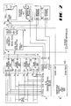
- FIG. 1 is a block diagram of the preferred embodiment of the present invention.
- the preferred embodiment comprises four trunk interface units 10a-10d, a system controller 11, a cross-point switch or PBX 13, a mainframe computer or host 16, and ten operator terminals 12a-12j.
- Sixteen trunk lines T1-T16 are connected to composite trunk interface unit 10 and cross-point switch 13.
- Each trunk interface unit 10a-10d accommodates four trunk lines so that trunk interface unit 10a services trunks T1-T4, trunk interface unit 10b services trunks T5-T8, and so forth.
- Each trunk interface unit 10a-10d performs one or more of the following functions: trunk seizure; dialing; call progress monitoring; message playing; message recording; voice recognition and analysis; automatic number identification; and/or dual tone multifrequency tone decoding.
- a trunk interface unit such as trunk interface unit 10a, preferably comprises a dialer 10a1, a call progress monitor 10a5, a message player and/or recorder 10a9, an incoming call detector 10a20, an automatic number identification (ANI) decoder 10a24, a dual tone, multifrequency (DTMF) decoder 10a28, a voice recognition module 10a32, and a trunk interface control unit 10a13. Details of the construction and operation of trunk interface units 10a-10d are explained in more detail in U.S. Patent No. 4,797,911.
- the parallel port of system controller 11 is connected by parallel bus 14 to the control inputs of switch 13.
- system controller 11 may control the operation of switch 13 through some other communication means or port, such as serial port SP15.
- serial port SP15 some other communication means or port
- the use of a serial port or a parallel port will, of course, be determined by the nature of the control input port of switch (or PBX) 13.
- system controller 11 has 16 serial ports SP1-SP16, a parallel port, a high speed serial port, and a local area network port.
- Serial port SP1 of system controller 11 is connected to the serial ports (SP) of trunk interface units 10a-10d through a standard multi-line drop. Controller 11 may, of course, be connected to units 10a-10d through any appropriate communications means.
- Each trunk interface unit 10a-10d has an address different from any other trunk interface unit so that system controller 11 may, via port SP1 and trunk interface units 10a-10d, monitor the status of trunk lines T1-T16.
- System controller 11, via serial port SP1 also commands trunk interface units 10a-10d to perform a desired operation on a specified trunk T1-T16.
- system controller 11 may command trunk interface unit 10a to seize trunk T1 and begin dialing a desired telephone number, command trunk interface unit 10a to begin playing a prerecorded message on trunk T2, and obtain information on the status of the trunks T1-T16. Also, the trunk interface units 10 may advise system controller 11 that a ringing signal (indicating an incoming call) is occurring on a particular trunk whereupon system controller 11 may command trunk interface units 10 to seize the trunk having incoming call, play a prerecorded message on that trunk, and evaluate the calling party's response to the prerecorded message.
- serial port SP1 is an RS-232C serial data port.
- Operator terminal 12a which is representative of operator terminals 12b-12j, has a telephone set 12a1, a handset 12a2, and/or a headset 12a3. Typically, a headset 12a3, and not handset 12a2, will be plugged into telephone 12a1 so as to free the operator's hands. It will be appreciated that, in environments in which headset 12a is always used, handset 12a2 may be eliminated. It will also be appreciated that, if the operator has no need to manually place outgoing calls, telephone set 12a1 may be replaced by a conventional trunk line-to-headset interface.
- Operator terminal 12a also has a data terminal 12a4, data terminal 12a4 having a display screen 12a5 and a keyboard 12a6.
- Data terminal 12a4 has a serial port (B) connected by coaxial cable, or other data transfer means, S2 to the SP2 serial port of system controller 11 and a high speed serial port (C) connected by a cable, or other data transfer means, HS2 to a high speed serial port of computer 16.
- Data terminal 12a4 may also have other types of ports for data transmission and retrieval, such as a telephone port for use by an internal modem (not shown) or a port for connection to an external modem (not shown).
- Operator terminals 12b-12j are likewise connected by conductors S3-S11 to the SP3-SP11 serial ports of system controller 11 and cables HS3-HS12 to the high speed serial ports of host 16.
- Line outputs OTL1-OTL10 of switch 13 are connected by telephone lines L1-L10, respectively, to the telephone sets 12a1-12j1 via the telephone inputs (A) of operator terminals 12a-12j, respectively.
- the high speed serial port of system controller 11 is connected by cable HS1 to a high speed serial port of mainframe computer (or other host) 16 to allow for file transfers and data manipulation.
- serial port SP16 of system controller 11 may be connected by cable S16 to a serial port of host 16 for this purpose.
- the local area network port of system controller 11 and the other serial ports of mainframe computer 16 may, if desired, be connected to other system controllers (not shown) via local area network cable LAN and additional serial cables ASC, respectively.
- system controller 11 can obtain information from mainframe 16 one account at a time. Also, depending upon the previously installed program in host 16, system controller 11 may obtain full account information, abbreviated account information, or compilations of certain account information such as, for example, a calling list. System controller 11 coordinates and performs such functions as causing trunk interface units 10 to seize a trunk line, dial a customer telephone number, monitor the status of the outgoing call, detect an incoming call, answer an incoming call, play prerecorded messages and determine the response from the called/calling party, record a called/calling party's response, etc. These functions of system controller 11 and the manner in which they are implemented are described in more detail in U.S. Patent No. 4,797,911.
- system controller 11 and each data terminal 12a4-12j4 is an IBM-AT, an IBM PS/2 Model 30, 60, or 80, or other computer programmed and equipped to emulate an operator terminal which is designed to interface with mainframe computer 16 via a high speed serial port or other communications means.
- system controller 11 and data terminals 12a4-12j4 are programmed to use exactly the same commands and data formats that are required by the customer's applications package already resident in computer 16. This allows substantial enhancement of the incoming and outgoing call processing capability by providing automated dialing, call progress monitoring, automatic answering, routing of incoming and outgoing calls, etc., without requiring that the applications program or other software for mainframe computer 16 be changed in any way.
- This also provides another advantage: operator training. If the operators are trained on one type of host applications program and terminal and have become accustomed to the commands used with that terminal and the displays provided at that terminal by the host applications program then, if the operator is provided with a new terminal which uses different commands and has a different screen display, there will be a period of substantially reduced productivity while the operator learns the particulars of the new data terminal. However, in the preferred embodiment the operator terminals replace and emulate the previously existing terminals so that the operator continues to use the same commands and procedures and still sees the same screen display as before. This substantially reduces or completely eliminates the period of reduced productivity. This also allows the data terminals 12a4-12j4 to communicate with host 16 using the commands, data formats and protocols that host 16 was previously programmed to use. The use of new data terminals 12a4-12j4 which emulate the previously existing data terminals and host applications interface allow substantial enhancement of incoming and outgoing call processing capability without requiring that the applications program or other software for host 16 be changed in any way.
- the present invention provides for substantially upgrading and enhancing the performance of an existing mainframe 16 without requiring a change in the applications program or other software for the mainframe computer 16 or requiring that the operators undergo retraining to learn new commands and display formats.
- Mainframe computer 16 will provide, by a batch transfer or online transfer, the customer account information for a desired number of accounts to system controller 11.
- System controller 11 then extracts, for each account, the name of the customer, the customer's telephone number, the account number, and/or some type of mainframe database index number. Assuming that trunk T1 is available, then system controller 11 will direct trunk interface unit 10a to seize trunk T1, provide the customers telephone number to trunk interface unit 10a, and direct trunk interface unit 10a to dial the customer's telephone number. Trunk interface unit 10a dials the customer's telephone number and then monitors trunk T1 for the status of the call.
- trunk interface unit 10a advises, via port SP, system controller 11 that the called number is busy, or is not answered, system controller 11 will mark, in its memory (not shown), the account accordingly and place the account in the queue to be tried again later.
- the memory associated with system controller 11 may be a semiconductor memory, such as RAM, or a disk memory system.
- Trunk interface unit 10a will automatically start a message player/recorder (Fig. 6) and advise system controller 11 that the call has been answered. If an operator is available, system controller 11 will send the abbreviated information (telephone number, customer name, account number, and/or database index number), to, for example, operator terminal 12a, direct cross-point switch 13, via bus 14, to connect trunk T1 to telephone 12a1 via line port OTL1, and then direct trunk interface unit 10a to release trunk T1 and stop the message player/recorder. The message player/recorder will then stop the message currently being played. The called party may never hear any part of the message since, if an operator is available, the operator will be immediately connected to the called party.
- abbreviated information telephone number, customer name, account number, and/or database index number
- Terminal 12a4 will display the abbreviated information on screen 12a5. Therefore, as soon as the operator at operator terminal 12a is connected with the customer on trunk T1, the operator has at least the abbreviated customer account information. If terminal 12a4 is a semi-smart terminal then the operator may obtain the full account information by pressing one or more keys on keypad 12a6 which causes terminal 12a4 to request the full account information from mainframe 16. Alternatively, if terminal 12a4 is a semi-smart terminal, then system controller 11 may instruct mainframe 16 to send the full account information to terminal 12a4 for display on screen 12a5.
- terminal 12a4 is a smart terminal then, upon receiving the abbreviated account information from system controller 11, terminal 12a4 may, without prompting from the operator, immediately request the full account information from mainframe 16.
- the result is that, with minimal or no effort by the operator, the customer has been called, the customer's answer has been detected, the operator has been connected to the customer, and the operator sees and can manipulate, on screen 12a5, the most current customer account information from mainframe 16. Therefore, the operator has not had to perform the inefficient and time consuming duties of requesting a telephone number, obtaining a trunk line, dialing the number, waiting for the party to answer, and obtaining current information on the customer account.
- the operator can then discuss the matter of reason for which the customer was called, for example, discussing a late payment account, collecting on a delinquent account, verifying an order, updating customer account information, etc., while being directly connected, online, to mainframe 16.
- Trunk unit 10a starts the message player/recorder and advises system control 11 that the called party has answered. After ascertaining that an operator is not available, system controller 11 will allow trunk interface unit 10a to continue playing the desired prerecorded message to the called party. As soon as system controller 11 determines that an operator is available, system controller 11 will cause cross-point switch 13 to connect the available operator terminal 12 to trunk T1, direct trunk interface unit 10a to release trunk T1, direct unit 10a to stop the message, advance to the next message, and send the abbreviated customer account information to the available operator terminal 12. Again, the operator will have the customer account information when the customer is connected and can then begin to discuss the reason for which the customer has been called.
- terminal 12a4 when the operator at operator terminal 12a has concluded the business with the customer the operator may press a telephone trunk release key on keyboard 12a6 to indicate that trunk T1 should be released.
- Terminal 12a4 sends the trunk release signal over serial port B to system controller 11.
- System controller 11 then directs cross-point switch 13 to disconnect telephone 12a1 from trunk T1.
- System controller 11 then sends the next telephone number to trunk interface unit 10a and directs trunk interface unit 10a to seize trunk T1 and dial this next telephone number. If another called party has answered then system controller 11 will cause that called party to be connected to the now-available operator.
- Terminal 12a4 sends this information to system controller 11 which advises system controller 11 that the operator at operator terminal 12a is available for the next call.
- System controller 11 then causes cross-point switch 13 to connect the next customer to telephone 12a1 and sends the abbreviated customer account information to terminal 12a4 for display on screen 12a5. Therefore, as soon as the operator at operator terminal 12a has indicated that processing of one customer account is completed system controller 11 connects the operator with the next called party. The result is that the operator's time is more efficiently and more completely utilized.
- a single key or single entry on keyboard 12a6 may indicate to system controller 11 that the connected trunk should be released and that the operator is available for the next customer.
- the present invention relieves the operator of the inefficient and time consuming duties of obtaining the telephone number, dialing the telephone number, and waiting for the called customer to answer. Also, when either an incoming or an outgoing call requires operator assistance, that call is immediately connected to an available operator, thereby further reducing the idle time of the operators. Also, it will be appreciated that the customer account information in the main database in mainframe computer 16 is immediately updated so that, at the end of the business day, it is not necessary to consolidate changes made by the operator(s) to the customer account information and also provides the benefit that, at any time during the day when the customer calls or is called, the customer account information available to the operator is the current, updated customer account information.
- system controller 11 is transparent to the host 16 and to the operator.
- System controller 11 automatically processes each call and routes the call to the first available operator. Therefore, any changes to the customer account information made by the operator are immediately provided to mainframe 16, which automatically and instantly updates the customer account information. Furthermore, because of the automatic updating, and information provided to an operator is the most current information. The operator therefore appears to be directly connected to mainframe 16.
- system controller 11 sends only the abbreviated customer account information to an operator terminal 12
- system controller 11 may retain the entire file for a customer account and send this entire record to the operator terminal, thereby eliminating the steps of sending the abbreviated account information to the operator terminal, sending the account number, telephone number, and/or database number to maintain 16 and then sending the full account information from mainframe 16 to the operator terminal.
- system controller 11 has 16 serial ports SP1-SP16, a parallel port, and a local area network port.
- Serial port SP1 of system controller 11 is connected to the serial ports (SP) of trunk interface units 10a-10d through a standard multi-line drop.
- Controller 11 may, of course, be connected to units 10a-10d through any appropriate communications means.
- Each trunk interface unit 10a-10d has an address different from any other trunk interface unit so that system controller 11 may, via port SP1 and trunk interface units 10a-10d, monitor the status of trunk lines T1-T16.
- System controller 11, via serial port SP1 also commands trunk interface units 10a-10d to perform a desired operation on a specified trunk T1-T16.
- system controller 11 may command trunk interface unit 10a to seize trunk T1 and begin dialing a desired telephone number, command trunk interface unit 10a to begin playing a prerecorded message on trunk T2, and obtain information on the status of the trunks T1-T16. Also, the trunk interface units 10 may advise system controller 11 that a ringing signal (indicating an incoming call) is occurring on a particular trunk whereupon system controller 11 may command trunk interface units 10 to seize the trunk having incoming call, play a prerecorded message on that trunk, and evaluate the calling party's response to the prerecorded message.
- Serial port SP1 is again an RS-232C serial data port.
- operator terminals 12a-12j are the previously existing operator terminals.
- Operator terminal 12a which is representative of operator terminals 12b-12j, has a telephone set 12a1, a handset 12a2, and/or a headset 12a3.
- a headset 12a3, and not handset 12a2 will be plugged into telephone 12a1 so as to free the operator's hands.
- handset 12a2 may be eliminated.
- telephone set 12a1 may be replaced by a conventional trunk line-to-headset interface.
- Operator terminal 12a also has a data terminal 12a4, data terminal 12a4 having a display screen 12a5 and a keyboard 12a6.
- Data terminal 12a4 has a serial port (B) connected by coaxial cable, or other data transfer means, S2 to the SP2 serial port of system controller 11.
- Data terminal 12a4 may also have other types of ports for data transmission and retrieval, such as a telephone port for use by an internal modem (not shown) or a port for connection to an external modem (not shown).
- Operator terminals 12b-12j are likewise connected by conductors S3-S11 to the SP3-SP11 serial ports of system controller 11.
- Line outputs OTL1-OTL10 of switch 13 are connected by telephone lines L1-L10, respectively, to the telephone sets 12a1-12j1 via the telephone inputs (A) of operator terminals 12a-12j, respectively.
- Serial port SP16 of system controller 11 is connected by conductor S16 to a serial port of mainframe computer (or other host) 16 to allow for file transfer and data manipulation.
- the local area network port of system controller 11 and the other serial ports of mainframe computer 16 may, if desired, be connected to other system controllers (not shown) via local area network cable LAN an additional serial cables ASC, respectively.
- system controller 11 can obtain information from mainframe 16 one account at a time. Also, depending upon the previously installed program in host 16, system controller 11 may obtain full account information, abbreviated account information, or compilations of certain account information such as, for example, a calling list. System controller 11 coordinates and performs such functions as causing trunk interface units 10 to seize a trunk line, dial a customer telephone number, monitor the status of the outgoing call, detect an incoming call, answer an incoming call, play prerecorded messages and determine the response from the called/calling party, record a called/calling party's response, etc. These functions of system controller 11 and the manner in which they are implemented are described in more detail in U.S. Patent No. 4,797,911.
- system controller 11 is again an IBM-AT, an IBM PS/2 Model 30,60, or 80, or other computer programmed and equipped to emulate an operator terminal which is designed to interface with mainframe computer 16 via the serial port.
- the serial port of mainframe 16 and data terminals 12a4-12j4 are RS-232C ports
- the ports SP2-SP11 and SP16 of system controller 11 would preferably also be RS-232C ports.
- system controller 11 is programmed to use exactly the same commands and data formats that are required by the applications package resident in computer 16.
- system controller 11 allows system controller 11 to substantially enhance the incoming and outgoing call processing capability of mainframe 16 and operator terminals 12a-12j by providing automated dialing, call progress monitoring, automatic answering, and routing of incoming and outgoing calls, etc., without requiring that the applications program or other software for mainframe computer 16 or operator terminals 12a-12j be replaced, changed, or modified in any way.
- a mainframe interface program 100 controls communications over the serial port which is connected to the serial port of mainframe computer 16.
- Operator terminal interface program 101 controls the data transfer on the serial ports which are connected to the serial ports (B) of operator terminals 12a-12j.
- Processing and control program 102 controls the operation of serial port SP1, which is connected to the trunk interface units 10 of Figures 1 and 2, the parallel port which is connected to switch 13 of Figures 1 and 2, and the local area network port LAN of Figures 1 and 2.
- Program 102 extracts the customer account number, the customer's name, the customer's telephone number, etc., from the customer account record received from mainframe computer 16.
- Mainframe interface program 100 converts between the commands or instructions and data formats required by mainframe computer 16 and the commands or instructions and data formats used by program 102.
- operator terminal interface program 101 converts between the commands and data formats required by the operator terminals 12a-12j and the commands or instructions and data formats used by processing and control program 102. This allows a standard processing and control program 102 to be written which performs the desired functions of system controller 11. Then, programs 100 and 101 provide the necessary interface between program 102 and the mainframe 16 and operator terminals 12. Therefore, rather than having a rewrite program 102 for each different type of system, it is only necessary to write interface programs 100 and 101. Furthermore, mainframe computer 16 and operator terminals 12 may continue to use the applications software and other programming with which they were originally equipped.
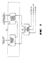
- FIG 4A is one example of a typical environment in which the present invention might be used.
- Mainframe computer 16 is connected by conductor HS1 or S16 to system controller 11 and by cables HS2-HS11 to operator terminals 12a-12j.
- System controller 11 is connected by conductors S2-S11 to operator terminals 12a-12j.
- System controller 11 is connected by conductor S1 to trunk interface units 10 and by parallel bus 14 to switch 13.
- Figure 4A is a simplified diagram of the environment of Figure 1. That is, upon receipt of the abbreviated account data from system controller 11 or upon entry of particular data, such as a name, account number, or telephone number, each data terminal 12 will directly request the full account data from host 16.
- the request may be initiated as a result of receiving the abbreviated account data or in response to one or more key entries by an operator.
- the data will pass between host 16 and the data terminal without requiring the intervention of system controller 11 or requiring any data to pass through system controller 11.
- FIG. 4A becomes a simplified diagram of the environment of Figure 2. That is, data transfers between mainframe computer 16 and operator terminals 12 must pass through system controller 11.
- System controller 11 therefore maintains interface capability with mainframe computer 16 and operator terminals 12 while enhancing the capabilities of the overall system by controlling the operation of trunk interface units 10 and switch 13.
- the data terminals may, upon receipt of the abbreviated account data from system controller 11 or upon entry of particular data, such as a name, account number, or telephone number, request the full account data from host 16 but, in this alternative environment, all requests from a data terminal must pass through system controller 11 and all data transfers between host 16 and a data terminal must pass through system controller 11.
- FIG 4B is a block diagram of another typical environment in which the embodiment of Figure 2 might be used.
- Mainframe computer 16 is connected to system controller 11.
- System controller 11 is connected to trunk interface units 10 and switch 13.
- the operator terminals 12 are two-port devices connected to host 16 via cable HS2-HS11. This allows data transfers to bypass system controller 11 so that system controller 11 need not function as a data conduit between host 16 and the terminals 12.
- the terminals 12 are capable of directly communicating with host 16 using the commands and data format required by the original applications program used by host 16.
- System controller 11 and operator terminals 12a-12j are connected in a ring network. Note that system controller 11 maintains compatibility with mainframe 16 on one side and maintains compatibility with a ring network comprising operator terminals 12a-12j on the other side.
- system controller 11 in addition to upgrading the system to provide the functions (automated dialing, automated answering, etc.) discussed previously and in U.S. Patent No. 4,797,911 system controller 11 also provides an interface between mainframe 16 and the ring network with which mainframe 16 may or may not have been previously compatible. In the preferred embodiment of this environment, system controller 11 and each terminal 12 can communicate directly with the host 16. Therefore, as in Figure 1, system controller 11 is responsible for the initiation, answering, and handling of telephone calls. System controller 11 also provides abbreviated customer account data to the terminals 12. The terminals 12, in an automatic response to receipt of the abbreviated data from system controller 11, or as a result of one or more key entries by the operator, request host 16 to provide the full data to the terminal 12. Therefore, in this configuration, it is necessary that the terminals 12 be compatible with host 16.
- terminals 12 are one-port devices so cables HS2-HS11 are not used. Therefore, all data must pass through system controller 11. However, since the data terminals 12 communicate with host 16 through system controller 11 it is not necessary for the terminals to be compatible with the host 16. System controller 11, in this case, acts as an interpreter between the command and data format structure required by host 16 and the command and data format structure used by the terminals. Therefore, another benefit of the present invention is that normally incompatible operator terminals 12 may be used with an existing computer 16 and its present programs by the addition of system controller 11. This benefit arises because the mainframe interface program 100 of Figure 3 may be different from or identical to the operator terminal interface program 101.
- FIG 4C is a block diagram of another environment in which the present invention might be used.
- mainframe computer 16, operator terminals 12, and system controller 11 are all connected to a ring network.
- System controller 11 is also connected to the trunk interface units 10 and switch 13.
- the operator terminal interface program 101 of Figure 2 might be eliminated and the mainframe interface program 100 of Figure 2 would be a ring network interface program.
- a system controller 11 or a plurality of system controllers can therefore be inserted into an existing ring network without requiring that the software used to drive the ring network be replaced or modified in any way.
- the data terminals would preferably be programmed to emulate the previously existing data terminals, and system controller 11 would be connected to the data terminals via cables HS2-HS11 and a host 16 via cable S16 or HS1. Cables HS2-HS11 are shown as dashed lines in Figure 4C.
- FIGS 5A and 5B1 are a flow chart of the operating programs of the system controller 11 where, as in Figure 1, system controller 11 is not required to transfer data between host 16 and terminals 12.
- Program 102 first requests 120 the data on another account from program 100.
- Program 100 receives and converts 110 the request from program 102 from the command and data format structure used by system controller 11 into the command and data format structure required by the host 16.
- Program 100 then sends the converted request to the host 16.
- Program 100 receives and converts 111 the account data or calling list, received from host 16, from the data format used by host 16 into the data format used by system controller 11.
- Program 100 then sends 111 the converted account data or calling list to program 102.
- step 121 program 102 receives the converted account data or calling list from program 100, extracts the customer telephone number from the account data or calling list, sends the telephone number to the trunk interface 10 for the placement of an outgoing call, monitors the call status, and if the call is answered proceeds to step 122.
- step 122 program 102 commands switch 13 to connect available operator terminals 12x to the appropriate telephone trunk T, and sends abbreviated account data to program 101.
- step 130 program 101 receives and converts the abbreviated account data from program 102 from the data format used by system controller 11 to the data format used by the operator terminals 12, and then sends the converted account data to operator terminal 12x.
- step 132 program 101 receives key entries made by the operator alt terminal 12x, converts the key entries from the data format and structure used by the operator terminals 12 into the data format and structure used by system controller 11, and sends these key entries to program 102.
- step 123 program 102 receives the converted key entries from program 101 and then processes the converted key entries.
- the software of some host computers may include an instruction for the host computer to send only abbreviated customer account data, such as a name, account number, and telephone number, and another instruction to send the full customer account file.
- Other systems may simply have one instruction which causes the host computer 16 to send the full customer account file.
- the present invention works with either type of system and, if an instruction to send abbreviated data is part of the host 16 software then, at step 120, system controller 11 may simply request the abbreviated data rather than the full account data.
- the terminal 12 When the system controller 11 sends the abbreviated data to a terminal 12, the terminal 12 requests host 16 to send the full account data. This request may be made in response to receipt of the abbreviated data or may be made in response to an operator key entry or entries at the data terminal 12.
- System controller 11 and terminals 12 emulate the characteristics of existing operator terminals so that mainframe computer 16 uses the same software with which it was originally equipped. Therefore, the operation of system controller 11 and the operator terminals 12 is transparent to the host 16. This allows the entire system to be extended or upgraded to an automated call handling system by the addition of system controller 11 but without requiring new software or applications programs for the host 16.
- FIGS. 5A and 5B1 are directed towards the handling of an outgoing call, it will be appreciated that the same technique, converting the commands and data between the different formats and structures, is equally applicable to the handling of processing of incoming calls.
- U.S. Patent No. 4,7977,911 describes in detail the preferred handling of an incoming call.
- the present invention provides another benefit in upgrading an existing system to provide for automated call handling: it is not necessary to retrain the operators of the operator terminals 12. Since the software is unchanged, the operation of the terminals is unchanged and the operators may continue to operate existing terminals in the manner that they have done before. If new terminals are acquired, the operators may continue to use the same commands and see the same screen displays as before. With either embodiment it is no longer necessary for the operator to initiate outgoing calls or answer incoming calls.
- FIGS 5A and 5B2 are a flow chart of the operating programs of the system controller 11 where, as in Figure 2, system controller 11 transfers data between host 16 and terminals 12.
- Figure 5B2 differs from figure 5B1 in that steps 112, 113, 114 and 131, substep 122a has been added, and step 132 has been modified.
- step 122a program 102 sends a request for full account data for terminal 12x to program 100.
- program 100 receives and converts the request for the full account data from the command and data format structure used by system controller 11 to be command and data format structure required by host 16, and sends the converted request to host 16.
- step 113 program 100 receives the account data from host 16 and then sends the account data to program 101.
- step 131 program 101 receives the account data from program 100 and then sends the account data to terminal 12x. It will be noted that, since host 16 and terminal 12x require, in this embodiment, the same command and data format structure, the account data was sent, without conversion, from step 113 of program 100 to step 131 of program 101. If host 16 and data terminal 12x require different command and data format structures then the conversion can be performed by program 100, program 101, or even program 102.
- program 101 sends the key entries to program 100.
- program 100 receives the key entries from program 101 and sends these key entries to host 16. It will again be noted that, since host 16 and terminal 12x require, in this embodiment, the same command and data format structure, the key entries were sent, without conversion from substep 132(2) of program 101 to step 114 of program 100. If host 16 and data terminal 12x require different command and data format structures then the conversion can be performed by program 100, program 101, or even program 102.
- the present invention allows for the continued use of existing terminals, the use of new terminals which emulate the existing terminals, and the use of new terminals which are incompatible with host 16, all without requiring any changes to the host 16 or the applications program previously installed in host 16.
- system controller 11 has access to all communications between mainframe 16 and operator terminals 12.
- system controller 11 monitors all communications between mainframe 16 and operator terminals 12 so that system controller 11 will know whether a particular operator terminal 12x is busy or available.
- system controller 11 may periodically poll the operator terminals 12 to determine whether a particular operator terminal 12x is available or is busy.
- mainframe 16 periodically polls the operator terminals 12 then system controller 11 may simply monitor the polling activity of mainframe 16 and the response of the operator terminals 12.
- system controller 11 evaluates and acts upon all communications regardless of whether the destination address in the communication indicates that the communication is intended for system controller 11.
- system controller 11 will send abbreviated account data to a data terminal 12x so that data terminal 12x will display an abbreviated screen.
- Data terminal 12x then requests the full account data from host 16.
- the data terminals 12 are smart terminals and, upon receipt of the abbreviated account data from system controller 11, automatically requests the full account data from host 16.
- system controller 11 when system controller 11 sends the abbreviated account data to data terminal 12x, system controller 11 will request host 16 to transfer the full account data to the data terminal 12x.
- system controller 11 may provide a source or destination address different from that of it own. For example, assume that in Figure 4C system controller 11 has determined that operator terminal 12b is available to handle the present telephone call. System controller 11 would then send to mainframe 16 a request for full account data. However, rather than inserting its own device address into the message to mainframe 16, system controller 11 would insert the address of operator terminal 12b into the message. Mainframe 16 would then send the account data to the device having the address specified in the request. In this case, the destination address would be that of operator terminal 12b so operator terminal 12b would receive the message from mainframe 16, inspect the device address, determine that it was the same as its own device address, accept the data, and display the data on its screen 12b5.
- system controller 11 using its own device address, requests the data from mainframe 16, receives the data from mainframe 16, and then retransmits the data with a device address corresponding to that of operator terminal 12b. Therefore, system controller 11, even while controlling the origination and/or transfer of command and/or data between host 16 and operator terminals 12, remains essentially transparent to mainframe 16 and operator terminals 12 so that reprogramming of mainframe 16 and operator terminals 12 is not required.
- system controller 11 using its own device address, requests one or more calling lists from mainframe 16, receives the data from mainframe 16, and instructs a trunk interface unit 10 to dial the next number in the calling list.
- system controller 11 Upon detection by a trunk interface unit 10 of an answer by the called party, system controller 11 will cause cross-point switch 13 to connect the appropriate trunk line T to the audio communications device 12a3 of an available operator.
- System controller 11 may then send the data from the calling list to the data terminal 12a4 and request host 16 to provide full data to the data terminal, may simply request host 16 to provide the full data to the data terminal, or may send the calling list data to the data terminal whereupon the data terminal requests the full account information from host 16.
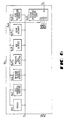
- the trunk interface unit 10a preferably contains a dialer 10a1, a call progress monitor 10a5, a message player/recorder 10a9, an incoming call detector 10a20, an automatic number indentification (ANI) decoder 10a24, a dual tone multiple frequency (DTMF) decoder 10a28, and a voice recognition module 10a32 for each trunk T1-T4.
- Dialer 10a1, call progress monitor 10a5, message player/recorder 10a9, incoming call detector 10a20, ANI decoder 10a24, DTMF decoder 10a28, and voice recognition module 10a32 are all connected to trunk T1.
- dialer 10a1, call progress monitor 10a5, message player/recorder 10a9, incoming call detector 10a20, ANI decoder 10a24, DTMF decoder 10a28, and voice recognition module 10a32 are all connected by bus 10a14 to the T1I port of trunk interface control unit 10a13.
- the function of dialer 10a1, call progress monitor 10a5, and message player 10a9 have been previously described.
- Incoming call detector 10a20 monitors trunk T1 and advises trunk interface control unit 10a13 when an incoming ringing signal appears on trunk T1.
- trunk interface control unit 10a13 will report an incoming call on trunk T1 to system controller 11 in the static status byte for trunk T1.
- trunk interface control unit 10a13 may direct ANI decoder 10a24 to obtain the telephone of the calling party, and direct message player/recorder 10a9 to seize the line and begin playing the prerecorded message or, alternatively, system controller 11 may instruct trunk interface control unit 10a13 to direct ANI decoder 10a24 and message player/recorder 10a9 to perform these functions.
- the message played by message player/recorder 10a9 may be a simple message advising the party that an operator will be connected as soon as one becomes available or, in conjunction with DTMF decoder 10a28, may query the customer for more information such as the customer's telephone number and/or account number.
- the local telephone office provides a service, sometimes called automatic number indentification (ANI).
- ANI automatic number indentification
- the central office will provide, over the trunk, tone signals, ISDN data signals, or other signals which can be decoded to yield the number from which the calling party is calling.
- a decoder such as ANI decoder 10a24 would provide the calling party's telephone number to trunk interface control unit 10a13. Trunk interface control unit 10a13 would then provide the calling party telephone number to system controller 11.
- System controller 11 requests mainframe 16 to provide the customer account information based upon the calling party telephone number.
- system controller 11 will connect the calling party to the available operator and also provide the calling party telephone number to the operator terminal for manual input.
- the operator can then conduct business with the calling party, obtain other information from the calling party, such as a name and/or an account number, enter this information via the keyboard to obtain the customer account information from mainframe 16, establish an account for a new customer etc.
- mainframe computer 16 will provide this information either to system controller 11 or to the next available operator terminal.
- system controller 11 will provide the abbreviated customer account information to the available operator terminal.
- the operator terminal will then, as previously described, obtain the full customer account information from mainframe 16. The operator can then conduct the necessary business with the customer.
- DTMF decoder 10a28 allows the customer to provide certain information via the DTMF keypad on his telephone set. For example, assume that ANI service is not available in the area. Upon being advised of an incoming call, trunk interface control unit 10a13 or system controller 11 will cause message player 10a9 to seize the line and begin playing the first prerecorded message.
- the first prerecorded message may be, for example, a message asking the calling party to key in the DTMF digit 1 if the calling party has an established account and the digit 2 if the calling party does not have an established account.
- message player 10a9 may query the customer and ask for an appropriate DTMF keypad response as to whether the customer wishes to open a new account, change an existing account, place, change or cancel an order, etc. Therefore, message player 10a9 may contain more than one message, the particular message to be played determined by the numbers which the calling keyed in over his DTMF keypad. Also, a message on message player 10a9 may ask the calling party to key in his telephone number and/or account number. This information would then be provided via trunk interface control unit 10a13 to system controller 11. When an operator becomes available, system controller 11 sends the information collected to the operator terminal for display upon the screen. Then, either automatically or in response to an operator keystroke, the operator terminal sends the collected information to mainframe 16. Mainframe 16 then provides the full customer account information to the operator terminal.
- the operator has been relieved of the time consuming and inefficient duties of answering the call, ascertaining the customer's account number, and keying in the customer's account number.
- the operator has the customer account information on screen immediately upon being connected to the calling party.
- the orders are placed, changed or cancelled by the calling party's use of the DTMF keypad it may not be necessary for the operator to intervene at all or, in the alternative, the operator may simply be connected in order to verbally verify the information provided by the calling party.
- System controller 11 is capable of automatic call distribution (ACD) routing of calls. Also, if different operators handle different types of calls, such as incoming calls, outgoing calls, establish new account, place or change an order, contact regarding a delinquent account, etc., system controller 11 automatically routes the incoming or outgoing call to the next available operator which handles that particular type of call. Therefore, the order and/or selection of which operator is connected to a particular call is controlled by system controller 11 on an ACD basis.
- ACD automatic call distribution
- Voice recognition module 10a32 allows some transactions to be completely handled without operator intervention and without requiring the customers to have a DTMF-type telephone.
- module 10a32 is the TeleRec system, manufactured by Voice Control Systems, Dallas, Texas. Details of operation of the TeleRec system are available from the manufacturer upon request.
- Module 10a32 provides digital output signals corresponding to a predetermined vocabulary, such as the spoken words one through nine, zero (oh), yes, no, help, cancel, and terminate.
- the TeleRec system also decodes DTMF tones and eliminates the need for a separate DTMF decoder 10a28.
- module 10a32 When module 10a32 is used, instead of immediately routing an incoming call or an answered outgoing call to an operator at an operator terminal 12a, the initial contact is handled by system controller 11.
- trunk interface control unit 10a13 When an incoming call or an outgoing call is answered trunk interface control unit 10a13 will cause message player/recorder 10a9 to begin playing the first prerecorded message.
- This prerecorded message contains instructions for the customer to speak the appropriate word, or words, alt the end of the message, to indicate the customer's response to the message.
- the response elicited may be, for example, an account number, a telephone number, a "yes" or a "no", etc.
- Module 10a32 decodes the customer's response and provides this response to system controller 11. Based upon the customer's response, system controller 11 may cause message player/recorder 10a9 to play an appropriate next message, disconnect trunk T1, or connect an available operator and provide the customer's responses to the operator's terminal for display on the screen.
- module 10a32 allows transactions to be automatically conducted both with customers who have DTMF telephones and with customers who have rotary dial (pulse) telephones.
- control of the call and monitoring of the customer's response need not be done solely by system controller 11 but may also be performed, wholly or partly, by an operator at a data terminal 12.
- a voice recognition module such as 10a32, could be switched, or multiplexed, between several trunks, instead of being dedicated to a single trunk.
- trunk interface control unit 10a13 controls this array of similar devices via its T2I-T4I ports over buses 10a15-10a17, respectively.
- the devices connected to a trunk used only for outgoing calls need not have an incoming call detector, an ANI decoder, or a DTMF decoder.
- dialer 10a1 and call progress monitor 10a5 are not required.
- U.S. Patent No. 4,797,911 discloses that a controller, such as system controller 11, can be used to maintain a record of the parameters (time of day, duration, busy, no answer, etc.) for each call. This technique may be used for the present invention. However, in the preferred embodiment of the present invention, one or more of the operator terminals 12 is configured to run without operator intervention or assistance. In this embodiment, system controller 11 will send an indication of the call status (busy, no answer, etc.) and some record identification key to the unattended operator terminal 12. This operator terminal 12 will send the record identification key to the host 16, obtain the customer account record from the host 16, and cause the host 16 to update the record to reflect the call status.
- system controller 11 will send an indication of the call status (busy, no answer, etc.) and some record identification key to the unattended operator terminal 12. This operator terminal 12 will send the record identification key to the host 16, obtain the customer account record from the host 16, and cause the host 16 to update the record to reflect the call status.
- the present invention provides a method and apparatus for retrofitting and upgrading an existing customer account servicing system to provide for automated handling and processing of both incoming and outgoing calls. This is accomplished without requiring new operating software or applications packages for the mainframe computer or the operator terminals.
- the retrofit is transparent of the operation of the mainframe and the operator terminals and significantly enhances the operation and capabilities of the existing system. Since other embodiments of the present invention may suggest to themselves to those skilled in the art based upon a reading of the foregoing disclosure, the present invention is to be limited only by the claims below.
Abstract
Description
- The present invention relates to customer account servicing systems in general and in particular to a method and apparatus for retrofitting existing systems to provide for the automated placement of telephone calls and the servicing of customer accounts.
- Many businesses, especially those with large numbers of customer accounts, periodically contact the customer by telephone to obtain updated account information, remind the customer of a past due account, collect on delinquent accounts, or conduct other business. In some installations, the operator sees a telephone number upon a screen and the number is either manually dialed by the operator or dialed by the operator's terminal in response to one or more keystroke inputs by the operator. The operator must then wait to determine if the call is answered, the call number is busy, is out of service, or has been changed, or to determine if there is no answer. For each call placed, there may be an elapsed time of several minutes wherein the operator is looking at the screen, dialing the number or causing the number to be dialed, and waiting for a response from the called number, which causes a significant part of the operator's time to be spent on non-productive tasks. Therefore, there is a need for a method and an apparatus which automatically dials the call without operator intervention or control and only connects the operator and displays the customer account record, which is resident in the mainframe or host computer, if the call is answered.
- U.S. Patent No. 4,599,493 discloses a system which automatically performs the call dialing and call progress monitoring functions, thereby relieving the operator of the need to manually dial the telephone number and wait for a response from the called number. However, a system such as that disclosed by Patent No. 4,599,493 requires that a customized interface program be written for the host computer. This arises because the dialing system must tell the host computer which telephone number has been called and which operator station has been selected for the audio connection so that the host computer can call up the record for the called number and transmit the record to the display of the selected operator. Applications software written for a host computer typically provides interface software so that the comlputer may exchange data with the operator terminals. However, the interface program generally does not include provisions for exchanging information with a dialing system such as that disclosed in U.S. Patent No. 4,599,493. Of course, a customized applications program, including the necessary interface software, can be written but the cost of such a customized program is often prohibitive.
- Therefore, there is a need for a method and apparatus which allows an existing customer account servicing system to be extendled or upgraded to provide for automated dialing and call progress monitoring without the necessity of modifying an existing applications program or purchasing a customized applications program to accommodate the extended or upgraded system.
- Also, the system disclosed in U.S. Patent No. 4,599,493 only accommodates outgoing calls. U.S. Patent No. 4,797,911, discloses a system which can automatically process incoming calls, thereby relieving the operator of the need to answer the call, ascertain the identity and/or account number of the calling party, determine what business the calling party wishes to transact, etc. It would be beneficial if an existing system could be upgraded to provide for automatic handling and processing of incoming calls.
- Therefore, there is a need for a method and apparatus which allows an existing customer account servicing system to be extended or upgraded for automated processing and handling of incoming calls without the necessity of purchasing a customized applications program or modifying an existing applications program to accommodate the upgraded system.
- The present invention provides a method and apparatus for extending or upgrading an existing customer account servicing system to provide for automated handling of both incoming and outgoing calls in a manner that is completely compatible with the existing software of the servicing system.
- More particularly described, the present invention provides a method and apparatus for upgrading an existing system to provide automatic dialing of telephone calls and call progress monitoring without the need for upgrading the host computer software.
- More particularly described, in one embodiment the present invention performs the automated dialing and call progress monitoring functions while also functioning as a transparent interface between the host and the operator terminals.
- Also more particularly described, the present invention provides a method and apparatus for upgrading an existing system to provide for the automatic handling and processing of incoming telephone calls without the need for upgrading the host computer software.
- Also more particularly described, in one embodiment the present invention performs the automated incoming call detection, call answering, and initial contact with the calling party while also functioning as a transparent interface between the host and the operator terminals.
- In another embodiment, the present invention, in addition to performing the automated dialing and call progress monitoring functions, causes the initiation of the data transfer between the host computer and the selected operator station.
- Therefore, it is an object of the present invention to provide a method and apparatus whereby an existing system can be upgraded to accommodate automated dialing and call progress monitoring without requiring that the host computer software be changed.
- It is another object of the present invention to provide a method and apparatus whereby an existing system can be upgraded to accommodate automated handling and processing of incoming calls without requiring that the host computer software be changed.
- It is a further object of the present invention to provide a method and apparatus which automates the handling and processing of incoming and outgoing calls while also functioning as a transparent interface between the host and the operator terminals.
-
- Figure 1 is a block diagram of the preferred embodiment of the present invention.
- Figure 2 is a block diagram of an alternative embodiment of the present invention.
- Figures 3A and 3B are block diagrams of the preferred embodiment of the present invention in typical environments.
- Figure 4A is one example of a typical environment in which the present invention might be used.
- Figure 4B is a block diagram of another typical environment in which the present invention might be used.
- Figure 4C is a block diagram of another environment in which the present invention might be used.
- Figures 5A and 5B1 are a flow chart of the operating programs of the preferred embodiment of the system controller.
- Figures 5A and 5B2 are a flow chart of the operating programs of an alternative embodiment of the system controller.
- Figure 6 is a block diagram of the preferred embodiment of a trunk interface unit.
- Turn now to the drawing in which like numerals represent like components throughout the several figures. Furthermore, wherever appropriate, the numeral/component relationship is the same as that used in the above mentioned U.S. Patent No. 4,797,911, which is hereby incorporated herein by reference. Figure 1 is a block diagram of the preferred embodiment of the present invention. The preferred embodiment comprises four
trunk interface units 10a-10d, asystem controller 11, a cross-point switch orPBX 13, a mainframe computer orhost 16, and tenoperator terminals 12a-12j. Sixteen trunk lines T1-T16 are connected to compositetrunk interface unit 10 andcross-point switch 13. Eachtrunk interface unit 10a-10d accommodates four trunk lines so thattrunk interface unit 10a services trunks T1-T4,trunk interface unit 10b services trunks T5-T8, and so forth. Eachtrunk interface unit 10a-10d performs one or more of the following functions: trunk seizure; dialing; call progress monitoring; message playing; message recording; voice recognition and analysis; automatic number identification; and/or dual tone multifrequency tone decoding. Referring briefly to Figure 6, which is a block diagram of a trunk interface unit, it will be seen that a trunk interface unit, such astrunk interface unit 10a, preferably comprises a dialer 10a1, a call progress monitor 10a5, a message player and/or recorder 10a9, an incoming call detector 10a20, an automatic number identification (ANI) decoder 10a24, a dual tone, multifrequency (DTMF) decoder 10a28, a voice recognition module 10a32, and a trunk interface control unit 10a13. Details of the construction and operation oftrunk interface units 10a-10d are explained in more detail in U.S. Patent No. 4,797,911. Returning to Figure 1, the parallel port ofsystem controller 11 is connected byparallel bus 14 to the control inputs ofswitch 13. It will also be appreciated thatsystem controller 11 may control the operation ofswitch 13 through some other communication means or port, such as serial port SP15. The use of a serial port or a parallel port will, of course, be determined by the nature of the control input port of switch (or PBX) 13. - In the preferred embodiment,
system controller 11 has 16 serial ports SP1-SP16, a parallel port, a high speed serial port, and a local area network port. Serial port SP1 ofsystem controller 11 is connected to the serial ports (SP) oftrunk interface units 10a-10d through a standard multi-line drop.Controller 11 may, of course, be connected tounits 10a-10d through any appropriate communications means. Eachtrunk interface unit 10a-10d has an address different from any other trunk interface unit so thatsystem controller 11 may, via port SP1 andtrunk interface units 10a-10d, monitor the status of trunk lines T1-T16.System controller 11, via serial port SP1, also commandstrunk interface units 10a-10d to perform a desired operation on a specified trunk T1-T16. For example,system controller 11 may commandtrunk interface unit 10a to seize trunk T1 and begin dialing a desired telephone number, commandtrunk interface unit 10a to begin playing a prerecorded message on trunk T2, and obtain information on the status of the trunks T1-T16. Also, thetrunk interface units 10 may advisesystem controller 11 that a ringing signal (indicating an incoming call) is occurring on a particular trunk whereuponsystem controller 11 may commandtrunk interface units 10 to seize the trunk having incoming call, play a prerecorded message on that trunk, and evaluate the calling party's response to the prerecorded message. In the preferred embodiment, serial port SP1 is an RS-232C serial data port. -
Operator terminal 12a, which is representative ofoperator terminals 12b-12j, has a telephone set 12a1, a handset 12a2, and/or a headset 12a3. Typically, a headset 12a3, and not handset 12a2, will be plugged into telephone 12a1 so as to free the operator's hands. It will be appreciated that, in environments in whichheadset 12a is always used, handset 12a2 may be eliminated. It will also be appreciated that, if the operator has no need to manually place outgoing calls, telephone set 12a1 may be replaced by a conventional trunk line-to-headset interface. -
Operator terminal 12a also has a data terminal 12a4, data terminal 12a4 having a display screen 12a5 and a keyboard 12a6. Data terminal 12a4 has a serial port (B) connected by coaxial cable, or other data transfer means, S2 to the SP2 serial port ofsystem controller 11 and a high speed serial port (C) connected by a cable, or other data transfer means, HS2 to a high speed serial port ofcomputer 16. Data terminal 12a4 may also have other types of ports for data transmission and retrieval, such as a telephone port for use by an internal modem (not shown) or a port for connection to an external modem (not shown).Operator terminals 12b-12j are likewise connected by conductors S3-S11 to the SP3-SP11 serial ports ofsystem controller 11 and cables HS3-HS12 to the high speed serial ports ofhost 16. Line outputs OTL1-OTL10 ofswitch 13 are connected by telephone lines L1-L10, respectively, to the telephone sets 12a1-12j1 via the telephone inputs (A) ofoperator terminals 12a-12j, respectively. - Although separate data cables (S2-S11, HS2-HS11) are shown for each data terminal it will be appreciated that all the (B) ports may be connected to one local area network serviced by, for example, cable S2, and that all the (C) ports may be connected to another LAN serviced by, for example, cable HS2 or cable HS1.
- The high speed serial port of
system controller 11 is connected by cable HS1 to a high speed serial port of mainframe computer (or other host) 16 to allow for file transfers and data manipulation. Alternatively, serial port SP16 ofsystem controller 11 may be connected by cable S16 to a serial port ofhost 16 for this purpose. The local area network port ofsystem controller 11 and the other serial ports ofmainframe computer 16 may, if desired, be connected to other system controllers (not shown) via local area network cable LAN and additional serial cables ASC, respectively. - Batch mode transfer from
comlputer 16 tosystem controller 11 is preferred but, if desired or required by the limitations of the applications software ofmainframe computer 16,system controller 11 can obtain information frommainframe 16 one account at a time. Also, depending upon the previously installed program inhost 16,system controller 11 may obtain full account information, abbreviated account information, or compilations of certain account information such as, for example, a calling list.System controller 11 coordinates and performs such functions as causingtrunk interface units 10 to seize a trunk line, dial a customer telephone number, monitor the status of the outgoing call, detect an incoming call, answer an incoming call, play prerecorded messages and determine the response from the called/calling party, record a called/calling party's response, etc. These functions ofsystem controller 11 and the manner in which they are implemented are described in more detail in U.S. Patent No. 4,797,911. - In the preferred embodiment,
system controller 11 and each data terminal 12a4-12j4 is an IBM-AT, an IBM PS/2 Model 30, 60, or 80, or other computer programmed and equipped to emulate an operator terminal which is designed to interface withmainframe computer 16 via a high speed serial port or other communications means. Furthermore,system controller 11 and data terminals 12a4-12j4 are programmed to use exactly the same commands and data formats that are required by the customer's applications package already resident incomputer 16. This allows substantial enhancement of the incoming and outgoing call processing capability by providing automated dialing, call progress monitoring, automatic answering, routing of incoming and outgoing calls, etc., without requiring that the applications program or other software formainframe computer 16 be changed in any way. - This also provides another advantage: operator training. If the operators are trained on one type of host applications program and terminal and have become accustomed to the commands used with that terminal and the displays provided at that terminal by the host applications program then, if the operator is provided with a new terminal which uses different commands and has a different screen display, there will be a period of substantially reduced productivity while the operator learns the particulars of the new data terminal. However, in the preferred embodiment the operator terminals replace and emulate the previously existing terminals so that the operator continues to use the same commands and procedures and still sees the same screen display as before. This substantially reduces or completely eliminates the period of reduced productivity. This also allows the data terminals 12a4-12j4 to communicate with
host 16 using the commands, data formats and protocols that host 16 was previously programmed to use. The use of new data terminals 12a4-12j4 which emulate the previously existing data terminals and host applications interface allow substantial enhancement of incoming and outgoing call processing capability without requiring that the applications program or other software forhost 16 be changed in any way. - Therefore, the present invention provides for substantially upgrading and enhancing the performance of an existing
mainframe 16 without requiring a change in the applications program or other software for themainframe computer 16 or requiring that the operators undergo retraining to learn new commands and display formats. - Consider now the operation of the preferred embodiment.
Mainframe computer 16 will provide, by a batch transfer or online transfer, the customer account information for a desired number of accounts tosystem controller 11.System controller 11 then extracts, for each account, the name of the customer, the customer's telephone number, the account number, and/or some type of mainframe database index number. Assuming that trunk T1 is available, thensystem controller 11 will directtrunk interface unit 10a to seize trunk T1, provide the customers telephone number totrunk interface unit 10a, and directtrunk interface unit 10a to dial the customer's telephone number.Trunk interface unit 10a dials the customer's telephone number and then monitors trunk T1 for the status of the call. Iftrunk interface unit 10a advises, via port SP,system controller 11 that the called number is busy, or is not answered,system controller 11 will mark, in its memory (not shown), the account accordingly and place the account in the queue to be tried again later. It will be appreciated that the memory associated withsystem controller 11 may be a semiconductor memory, such as RAM, or a disk memory system. - Assume now that the customer answers the call.
Trunk interface unit 10a will automatically start a message player/recorder (Fig. 6) and advisesystem controller 11 that the call has been answered. If an operator is available,system controller 11 will send the abbreviated information (telephone number, customer name, account number, and/or database index number), to, for example,operator terminal 12a, directcross-point switch 13, viabus 14, to connect trunk T1 to telephone 12a1 via line port OTL1, and then directtrunk interface unit 10a to release trunk T1 and stop the message player/recorder. The message player/recorder will then stop the message currently being played. The called party may never hear any part of the message since, if an operator is available, the operator will be immediately connected to the called party. Terminal 12a4 will display the abbreviated information on screen 12a5. Therefore, as soon as the operator atoperator terminal 12a is connected with the customer on trunk T1, the operator has at least the abbreviated customer account information. If terminal 12a4 is a semi-smart terminal then the operator may obtain the full account information by pressing one or more keys on keypad 12a6 which causes terminal 12a4 to request the full account information frommainframe 16. Alternatively, if terminal 12a4 is a semi-smart terminal, thensystem controller 11 may instructmainframe 16 to send the full account information to terminal 12a4 for display on screen 12a5. - If terminal 12a4 is a smart terminal then, upon receiving the abbreviated account information from
system controller 11, terminal 12a4 may, without prompting from the operator, immediately request the full account information frommainframe 16. The result is that, with minimal or no effort by the operator, the customer has been called, the customer's answer has been detected, the operator has been connected to the customer, and the operator sees and can manipulate, on screen 12a5, the most current customer account information frommainframe 16. Therefore, the operator has not had to perform the inefficient and time consuming duties of requesting a telephone number, obtaining a trunk line, dialing the number, waiting for the party to answer, and obtaining current information on the customer account. - Once connected, the operator can then discuss the matter of reason for which the customer was called, for example, discussing a late payment account, collecting on a delinquent account, verifying an order, updating customer account information, etc., while being directly connected, online, to
mainframe 16. - Assume now that when the party called on trunk T1 answered, an operator was not available.
Trunk unit 10a starts the message player/recorder and advisessystem control 11 that the called party has answered. After ascertaining that an operator is not available,system controller 11 will allowtrunk interface unit 10a to continue playing the desired prerecorded message to the called party. As soon assystem controller 11 determines that an operator is available,system controller 11 will causecross-point switch 13 to connect theavailable operator terminal 12 to trunk T1, directtrunk interface unit 10a to release trunk T1,direct unit 10a to stop the message, advance to the next message, and send the abbreviated customer account information to theavailable operator terminal 12. Again, the operator will have the customer account information when the customer is connected and can then begin to discuss the reason for which the customer has been called. - In the preferred embodiment, when the operator at
operator terminal 12a has concluded the business with the customer the operator may press a telephone trunk release key on keyboard 12a6 to indicate that trunk T1 should be released. Terminal 12a4 sends the trunk release signal over serial port B tosystem controller 11.System controller 11 then directscross-point switch 13 to disconnect telephone 12a1 from trunk T1.System controller 11 then sends the next telephone number totrunk interface unit 10a and directstrunk interface unit 10a to seize trunk T1 and dial this next telephone number. If another called party has answered thensystem controller 11 will cause that called party to be connected to the now-available operator. - When the operator at
operator terminal 12a has completed entering any new data for the particular customer account then the operator at terminal 12a may press a terminal release key on keyboard 12a6. Terminal 12a4 sends this information tosystem controller 11 which advisessystem controller 11 that the operator atoperator terminal 12a is available for the next call.System controller 11 then causescross-point switch 13 to connect the next customer to telephone 12a1 and sends the abbreviated customer account information to terminal 12a4 for display on screen 12a5. Therefore, as soon as the operator atoperator terminal 12a has indicated that processing of one customer account is completedsystem controller 11 connects the operator with the next called party. The result is that the operator's time is more efficiently and more completely utilized. - Alternatively, a single key or single entry on keyboard 12a6 may indicate to
system controller 11 that the connected trunk should be released and that the operator is available for the next customer. - From the above, it will be appreciated that the present invention relieves the operator of the inefficient and time consuming duties of obtaining the telephone number, dialing the telephone number, and waiting for the called customer to answer. Also, when either an incoming or an outgoing call requires operator assistance, that call is immediately connected to an available operator, thereby further reducing the idle time of the operators. Also, it will be appreciated that the customer account information in the main database in
mainframe computer 16 is immediately updated so that, at the end of the business day, it is not necessary to consolidate changes made by the operator(s) to the customer account information and also provides the benefit that, at any time during the day when the customer calls or is called, the customer account information available to the operator is the current, updated customer account information. - It will also be appreciated that the operation of
system controller 11 is transparent to thehost 16 and to the operator.System controller 11 automatically processes each call and routes the call to the first available operator. Therefore, any changes to the customer account information made by the operator are immediately provided tomainframe 16, which automatically and instantly updates the customer account information. Furthermore, because of the automatic updating, and information provided to an operator is the most current information. The operator therefore appears to be directly connected tomainframe 16. - Although, in the preferred embodiment,
system controller 11 sends only the abbreviated customer account information to anoperator terminal 12, ifsystem controller 11 has sufficient memory capacity,system controller 11 may retain the entire file for a customer account and send this entire record to the operator terminal, thereby eliminating the steps of sending the abbreviated account information to the operator terminal, sending the account number, telephone number, and/or database number to maintain 16 and then sending the full account information frommainframe 16 to the operator terminal. - In an alternative embodiment of Figure 1, no attempt is made to continue using an existing application program in
host 16. That is, a new applications program may be installed inhost 16 so that it is no longer necessary forsystem controller 11 or thedata terminals 12 to emulate any particular data terminal. In this alternative embodiment the interaction betweensystem controller 11,terminals 12, andhost 16 is the same as previously described except that different command and data format structures may be used. This alternative embodiment also allows substantial enhancement of the incoming and outgoing call processing capability by providing automated dialing, call progress monitoring, automatic answering, routing of incoming and outgoing calls, etc. Therefore, it will be appreciated that the present invention is not limited soley to systems where the existing applications software ofhost 16 is to be used. - Turn now to Figure 2 which is a block diagram of an alternative embodiment of the present invention. In this alternative embodiment,
system controller 11 has 16 serial ports SP1-SP16, a parallel port, and a local area network port. Serial port SP1 ofsystem controller 11 is connected to the serial ports (SP) oftrunk interface units 10a-10d through a standard multi-line drop.Controller 11 may, of course, be connected tounits 10a-10d through any appropriate communications means. Eachtrunk interface unit 10a-10d has an address different from any other trunk interface unit so thatsystem controller 11 may, via port SP1 andtrunk interface units 10a-10d, monitor the status of trunk lines T1-T16.System controller 11, via serial port SP1, also commandstrunk interface units 10a-10d to perform a desired operation on a specified trunk T1-T16. For example,system controller 11 may commandtrunk interface unit 10a to seize trunk T1 and begin dialing a desired telephone number, commandtrunk interface unit 10a to begin playing a prerecorded message on trunk T2, and obtain information on the status of the trunks T1-T16. Also, thetrunk interface units 10 may advisesystem controller 11 that a ringing signal (indicating an incoming call) is occurring on a particular trunk whereuponsystem controller 11 may commandtrunk interface units 10 to seize the trunk having incoming call, play a prerecorded message on that trunk, and evaluate the calling party's response to the prerecorded message. Serial port SP1 is again an RS-232C serial data port. - In this alternative embodiment,
operator terminals 12a-12j are the previously existing operator terminals.Operator terminal 12a, which is representative ofoperator terminals 12b-12j, has a telephone set 12a1, a handset 12a2, and/or a headset 12a3. Typically, a headset 12a3, and not handset 12a2, will be plugged into telephone 12a1 so as to free the operator's hands. It will be appreciated that, in environments in whichheadset 12a is always used, handset 12a2 may be eliminated. It will also be appreciated that, if the operator has no need to manually place outgoing calls, telephone set 12a1 may be replaced by a conventional trunk line-to-headset interface. -
Operator terminal 12a also has a data terminal 12a4, data terminal 12a4 having a display screen 12a5 and a keyboard 12a6. Data terminal 12a4 has a serial port (B) connected by coaxial cable, or other data transfer means, S2 to the SP2 serial port ofsystem controller 11. Data terminal 12a4 may also have other types of ports for data transmission and retrieval, such as a telephone port for use by an internal modem (not shown) or a port for connection to an external modem (not shown).Operator terminals 12b-12j are likewise connected by conductors S3-S11 to the SP3-SP11 serial ports ofsystem controller 11. Line outputs OTL1-OTL10 ofswitch 13 are connected by telephone lines L1-L10, respectively, to the telephone sets 12a1-12j1 via the telephone inputs (A) ofoperator terminals 12a-12j, respectively. - Serial port SP16 of
system controller 11 is connected by conductor S16 to a serial port of mainframe computer (or other host) 16 to allow for file transfer and data manipulation. The local area network port ofsystem controller 11 and the other serial ports ofmainframe computer 16 may, if desired, be connected to other system controllers (not shown) via local area network cable LAN an additional serial cables ASC, respectively. - Batch mode transfer from
computer 16 tosystem controller 11 is preferred but, if desired or required by the limitations of the applications software ofmainframe computer 16,system controller 11 can obtain information frommainframe 16 one account at a time. Also, depending upon the previously installed program inhost 16,system controller 11 may obtain full account information, abbreviated account information, or compilations of certain account information such as, for example, a calling list.System controller 11 coordinates and performs such functions as causingtrunk interface units 10 to seize a trunk line, dial a customer telephone number, monitor the status of the outgoing call, detect an incoming call, answer an incoming call, play prerecorded messages and determine the response from the called/calling party, record a called/calling party's response, etc. These functions ofsystem controller 11 and the manner in which they are implemented are described in more detail in U.S. Patent No. 4,797,911. - In this embodiment,
system controller 11 is again an IBM-AT, an IBM PS/2 Model 30,60, or 80, or other computer programmed and equipped to emulate an operator terminal which is designed to interface withmainframe computer 16 via the serial port. For example, if the serial port ofmainframe 16 and data terminals 12a4-12j4 are RS-232C ports, the ports SP2-SP11 and SP16 ofsystem controller 11 would preferably also be RS-232C ports. Furthermore,system controller 11 is programmed to use exactly the same commands and data formats that are required by the applications package resident incomputer 16. This allowssystem controller 11 to substantially enhance the incoming and outgoing call processing capability ofmainframe 16 andoperator terminals 12a-12j by providing automated dialing, call progress monitoring, automatic answering, and routing of incoming and outgoing calls, etc., without requiring that the applications program or other software formainframe computer 16 oroperator terminals 12a-12j be replaced, changed, or modified in any way. - In an alternative embodiment of Figure 2, no attempt is made to continue using the applications software previously existing in
mainframe 16. That is, one or more new applications programs may be installed inmainframe 16, andsystem controller 11 uses the command and data format structure required by the new applications programs. Sincesystem controller 11 acts as an interpreter betweenhost 16 and theoperator terminals 12, theoperator terminals 12 may, but need not, use the same command and data format structure as that used by the new applications programs. Therefore, the present invention is not limited to systems which continue to use existing applications programs. - Turn now to Figure 3 which is an illustration of the programming packages contained in
system controller 11. Amainframe interface program 100 controls communications over the serial port which is connected to the serial port ofmainframe computer 16. In the preferred embodiment, a high speed serial port ofmainframe 16 is used. Operatorterminal interface program 101 controls the data transfer on the serial ports which are connected to the serial ports (B) ofoperator terminals 12a-12j. Processing andcontrol program 102 controls the operation of serial port SP1, which is connected to thetrunk interface units 10 of Figures 1 and 2, the parallel port which is connected to switch 13 of Figures 1 and 2, and the local area network port LAN of Figures 1 and 2.Program 102 extracts the customer account number, the customer's name, the customer's telephone number, etc., from the customer account record received frommainframe computer 16. -
Mainframe interface program 100 converts between the commands or instructions and data formats required bymainframe computer 16 and the commands or instructions and data formats used byprogram 102. Likewise, operatorterminal interface program 101 converts between the commands and data formats required by theoperator terminals 12a-12j and the commands or instructions and data formats used by processing andcontrol program 102. This allows a standard processing andcontrol program 102 to be written which performs the desired functions ofsystem controller 11. Then,programs program 102 and themainframe 16 andoperator terminals 12. Therefore, rather than having arewrite program 102 for each different type of system, it is only necessary to writeinterface programs mainframe computer 16 andoperator terminals 12 may continue to use the applications software and other programming with which they were originally equipped. This allows the user to either continue using existing data terminals or acquire new data terminals, as desired. Therefore, it is possible to significantly extend or upgrade an existing system by the addition ofsystem controller 11 andtrunk interface units 10 but without the necessity of obtaining new applications programs and software formainframe computer 16. - Turn now to Figure 4A which is one example of a typical environment in which the present invention might be used.
Mainframe computer 16 is connected by conductor HS1 or S16 tosystem controller 11 and by cables HS2-HS11 tooperator terminals 12a-12j.System controller 11 is connected by conductors S2-S11 tooperator terminals 12a-12j.System controller 11 is connected by conductor S1 totrunk interface units 10 and byparallel bus 14 to switch 13. It will be appreciated that Figure 4A is a simplified diagram of the environment of Figure 1. That is, upon receipt of the abbreviated account data fromsystem controller 11 or upon entry of particular data, such as a name, account number, or telephone number, eachdata terminal 12 will directly request the full account data fromhost 16. The request may be initiated as a result of receiving the abbreviated account data or in response to one or more key entries by an operator. In any event, the data will pass betweenhost 16 and the data terminal without requiring the intervention ofsystem controller 11 or requiring any data to pass throughsystem controller 11. - If cables HS2-HS11 are eliminated, then the diagram of Figure 4A becomes a simplified diagram of the environment of Figure 2. That is, data transfers between
mainframe computer 16 andoperator terminals 12 must pass throughsystem controller 11.System controller 11 therefore maintains interface capability withmainframe computer 16 andoperator terminals 12 while enhancing the capabilities of the overall system by controlling the operation oftrunk interface units 10 andswitch 13. The data terminals may, upon receipt of the abbreviated account data fromsystem controller 11 or upon entry of particular data, such as a name, account number, or telephone number, request the full account data fromhost 16 but, in this alternative environment, all requests from a data terminal must pass throughsystem controller 11 and all data transfers betweenhost 16 and a data terminal must pass throughsystem controller 11. - Figure 4B is a block diagram of another typical environment in which the embodiment of Figure 2 might be used.
Mainframe computer 16 is connected tosystem controller 11.System controller 11 is connected totrunk interface units 10 andswitch 13. Theoperator terminals 12 are two-port devices connected to host 16 via cable HS2-HS11. This allows data transfers to bypasssystem controller 11 so thatsystem controller 11 need not function as a data conduit betweenhost 16 and theterminals 12. Theterminals 12 are capable of directly communicating withhost 16 using the commands and data format required by the original applications program used byhost 16.System controller 11 andoperator terminals 12a-12j are connected in a ring network. Note thatsystem controller 11 maintains compatibility withmainframe 16 on one side and maintains compatibility with a ring network comprisingoperator terminals 12a-12j on the other side. Therefore, in addition to upgrading the system to provide the functions (automated dialing, automated answering, etc.) discussed previously and in U.S. Patent No. 4,797,911system controller 11 also provides an interface betweenmainframe 16 and the ring network with whichmainframe 16 may or may not have been previously compatible. In the preferred embodiment of this environment,system controller 11 and each terminal 12 can communicate directly with thehost 16. Therefore, as in Figure 1,system controller 11 is responsible for the initiation, answering, and handling of telephone calls.System controller 11 also provides abbreviated customer account data to theterminals 12. Theterminals 12, in an automatic response to receipt of the abbreviated data fromsystem controller 11, or as a result of one or more key entries by the operator,request host 16 to provide the full data to the terminal 12. Therefore, in this configuration, it is necessary that theterminals 12 be compatible withhost 16. - In an alternative embodiment,
terminals 12 are one-port devices so cables HS2-HS11 are not used. Therefore, all data must pass throughsystem controller 11. However, since thedata terminals 12 communicate withhost 16 throughsystem controller 11 it is not necessary for the terminals to be compatible with thehost 16.System controller 11, in this case, acts as an interpreter between the command and data format structure required byhost 16 and the command and data format structure used by the terminals. Therefore, another benefit of the present invention is that normallyincompatible operator terminals 12 may be used with an existingcomputer 16 and its present programs by the addition ofsystem controller 11. This benefit arises because themainframe interface program 100 of Figure 3 may be different from or identical to the operatorterminal interface program 101. - Figure 4C is a block diagram of another environment in which the present invention might be used. In the preferred embodiment of this case,
mainframe computer 16,operator terminals 12, andsystem controller 11 are all connected to a ring network.System controller 11 is also connected to thetrunk interface units 10 andswitch 13. In this case, the operatorterminal interface program 101 of Figure 2 might be eliminated and themainframe interface program 100 of Figure 2 would be a ring network interface program. Asystem controller 11 or a plurality of system controllers can therefore be inserted into an existing ring network without requiring that the software used to drive the ring network be replaced or modified in any way. - If
new operator terminals 12, with a high speed port (C) are used, then the data terminals would preferably be programmed to emulate the previously existing data terminals, andsystem controller 11 would be connected to the data terminals via cables HS2-HS11 and ahost 16 via cable S16 or HS1. Cables HS2-HS11 are shown as dashed lines in Figure 4C. - Turn now to Figures 5A and 5B1 which are a flow chart of the operating programs of the
system controller 11 where, as in Figure 1,system controller 11 is not required to transfer data betweenhost 16 andterminals 12.Program 102first requests 120 the data on another account fromprogram 100.Program 100 then receives and converts 110 the request fromprogram 102 from the command and data format structure used bysystem controller 11 into the command and data format structure required by thehost 16.Program 100 then sends the converted request to thehost 16.Program 100 then receives and converts 111 the account data or calling list, received fromhost 16, from the data format used byhost 16 into the data format used bysystem controller 11.Program 100 then sends 111 the converted account data or calling list toprogram 102. In step 121program 102 receives the converted account data or calling list fromprogram 100, extracts the customer telephone number from the account data or calling list, sends the telephone number to thetrunk interface 10 for the placement of an outgoing call, monitors the call status, and if the call is answered proceeds to step 122. - In
step 122program 102 commands switch 13 to connect available operator terminals 12x to the appropriate telephone trunk T, and sends abbreviated account data toprogram 101. Instep 130program 101 receives and converts the abbreviated account data fromprogram 102 from the data format used bysystem controller 11 to the data format used by theoperator terminals 12, and then sends the converted account data to operator terminal 12x. - In
step 132,program 101 receives key entries made by the operator alt terminal 12x, converts the key entries from the data format and structure used by theoperator terminals 12 into the data format and structure used bysystem controller 11, and sends these key entries toprogram 102. Instep 123,program 102 receives the converted key entries fromprogram 101 and then processes the converted key entries. - The software of some host computers may include an instruction for the host computer to send only abbreviated customer account data, such as a name, account number, and telephone number, and another instruction to send the full customer account file. Other systems may simply have one instruction which causes the
host computer 16 to send the full customer account file. The present invention works with either type of system and, if an instruction to send abbreviated data is part of thehost 16 software then, atstep 120,system controller 11 may simply request the abbreviated data rather than the full account data. - When the
system controller 11 sends the abbreviated data to a terminal 12, the terminal 12 requests host 16 to send the full account data. This request may be made in response to receipt of the abbreviated data or may be made in response to an operator key entry or entries at thedata terminal 12. -
System controller 11 andterminals 12 emulate the characteristics of existing operator terminals so thatmainframe computer 16 uses the same software with which it was originally equipped. Therefore, the operation ofsystem controller 11 and theoperator terminals 12 is transparent to thehost 16. This allows the entire system to be extended or upgraded to an automated call handling system by the addition ofsystem controller 11 but without requiring new software or applications programs for thehost 16. Although the flow chart of Figures 5A and 5B1 are directed towards the handling of an outgoing call, it will be appreciated that the same technique, converting the commands and data between the different formats and structures, is equally applicable to the handling of processing of incoming calls. U.S. Patent No. 4,7977,911, describes in detail the preferred handling of an incoming call. - Since the operation of
system controller 11 is essentially transparent and does not require new or different software or programming for thehost 16 and theoperator terminals 12 emulate the previously used terminals, the present invention provides another benefit in upgrading an existing system to provide for automated call handling: it is not necessary to retrain the operators of theoperator terminals 12. Since the software is unchanged, the operation of the terminals is unchanged and the operators may continue to operate existing terminals in the manner that they have done before. If new terminals are acquired, the operators may continue to use the same commands and see the same screen displays as before. With either embodiment it is no longer necessary for the operator to initiate outgoing calls or answer incoming calls. - In the environment of Figure 2,
system controller 11 transfers the data betweenhost 16 andterminals 12. Figures 5A and 5B2 are a flow chart of the operating programs of thesystem controller 11 where, as in Figure 2,system controller 11 transfers data betweenhost 16 andterminals 12. Figure 5B2 differs from figure 5B1 in that steps 112, 113, 114 and 131,substep 122a has been added, and step 132 has been modified. - In
step 122a,program 102 sends a request for full account data for terminal 12x toprogram 100. Instep 112,program 100 receives and converts the request for the full account data from the command and data format structure used bysystem controller 11 to be command and data format structure required byhost 16, and sends the converted request to host 16. Instep 113,program 100 receives the account data fromhost 16 and then sends the account data toprogram 101. Instep 131,program 101 receives the account data fromprogram 100 and then sends the account data to terminal 12x. It will be noted that, sincehost 16 and terminal 12x require, in this embodiment, the same command and data format structure, the account data was sent, without conversion, fromstep 113 ofprogram 100 to step 131 ofprogram 101. Ifhost 16 and data terminal 12x require different command and data format structures then the conversion can be performed byprogram 100,program 101, or evenprogram 102. - In substep 132(2),
program 101 sends the key entries toprogram 100. Instep 114,program 100 receives the key entries fromprogram 101 and sends these key entries to host 16. It will again be noted that, sincehost 16 and terminal 12x require, in this embodiment, the same command and data format structure, the key entries were sent, without conversion from substep 132(2) ofprogram 101 to step 114 ofprogram 100. Ifhost 16 and data terminal 12x require different command and data format structures then the conversion can be performed byprogram 100,program 101, or evenprogram 102. - It will therefore be appreciated that the present invention allows for the continued use of existing terminals, the use of new terminals which emulate the existing terminals, and the use of new terminals which are incompatible with
host 16, all without requiring any changes to thehost 16 or the applications program previously installed inhost 16. - It will be appreciated from an inspection of Figures 4A-4C that
system controller 11 has access to all communications betweenmainframe 16 andoperator terminals 12. In the preferredembodiment system controller 11 monitors all communications betweenmainframe 16 andoperator terminals 12 so thatsystem controller 11 will know whether a particular operator terminal 12x is busy or available. Alternatively,system controller 11 may periodically poll theoperator terminals 12 to determine whether a particular operator terminal 12x is available or is busy. Alternatively, ifmainframe 16 periodically polls theoperator terminals 12 thensystem controller 11 may simply monitor the polling activity ofmainframe 16 and the response of theoperator terminals 12. In networks where source and/or destination address are used as part of the command and data format or structure then, in order to monitor the activity ofmainframe 16 andoperator terminals 12system controller 11 evaluates and acts upon all communications regardless of whether the destination address in the communication indicates that the communication is intended forsystem controller 11. - In the preferred embodiment,
system controller 11 will send abbreviated account data to a data terminal 12x so that data terminal 12x will display an abbreviated screen. Data terminal 12x then requests the full account data fromhost 16. In the preferred embodiment, thedata terminals 12 are smart terminals and, upon receipt of the abbreviated account data fromsystem controller 11, automatically requests the full account data fromhost 16. - In an alternative embodiment, when
system controller 11 sends the abbreviated account data to data terminal 12x,system controller 11 will requesthost 16 to transfer the full account data to the data terminal 12x. - Also, when sending a command and/or data,
system controller 11 may provide a source or destination address different from that of it own. For example, assume that in Figure4C system controller 11 has determined thatoperator terminal 12b is available to handle the present telephone call.System controller 11 would then send to mainframe 16 a request for full account data. However, rather than inserting its own device address into the message tomainframe 16,system controller 11 would insert the address ofoperator terminal 12b into the message.Mainframe 16 would then send the account data to the device having the address specified in the request. In this case, the destination address would be that ofoperator terminal 12b sooperator terminal 12b would receive the message frommainframe 16, inspect the device address, determine that it was the same as its own device address, accept the data, and display the data on its screen 12b5. - In an alternative embodiment,
system controller 11, using its own device address, requests the data frommainframe 16, receives the data frommainframe 16, and then retransmits the data with a device address corresponding to that ofoperator terminal 12b. Therefore,system controller 11, even while controlling the origination and/or transfer of command and/or data betweenhost 16 andoperator terminals 12, remains essentially transparent tomainframe 16 andoperator terminals 12 so that reprogramming ofmainframe 16 andoperator terminals 12 is not required. - In another alternative embodiment,
system controller 11, using its own device address, requests one or more calling lists frommainframe 16, receives the data frommainframe 16, and instructs atrunk interface unit 10 to dial the next number in the calling list. Upon detection by atrunk interface unit 10 of an answer by the called party,system controller 11 will causecross-point switch 13 to connect the appropriate trunk line T to the audio communications device 12a3 of an available operator.System controller 11 may then send the data from the calling list to the data terminal 12a4 andrequest host 16 to provide full data to the data terminal, may simply requesthost 16 to provide the full data to the data terminal, or may send the calling list data to the data terminal whereupon the data terminal requests the full account information fromhost 16. - Turn now to Figure 6 which is a block diagram of a typical
trunk interface unit 10a constructed to handle both incoming and outgoing calls. Thetrunk interface unit 10a preferably contains a dialer 10a1, a call progress monitor 10a5, a message player/recorder 10a9, an incoming call detector 10a20, an automatic number indentification (ANI) decoder 10a24, a dual tone multiple frequency (DTMF) decoder 10a28, and a voice recognition module 10a32 for each trunk T1-T4. Dialer 10a1, call progress monitor 10a5, message player/recorder 10a9, incoming call detector 10a20, ANI decoder 10a24, DTMF decoder 10a28, and voice recognition module 10a32 are all connected to trunk T1. Likewise, dialer 10a1, call progress monitor 10a5, message player/recorder 10a9, incoming call detector 10a20, ANI decoder 10a24, DTMF decoder 10a28, and voice recognition module 10a32 are all connected by bus 10a14 to the T1I port of trunk interface control unit 10a13. The function of dialer 10a1, call progress monitor 10a5, and message player 10a9 have been previously described. - Incoming call detector 10a20 monitors trunk T1 and advises trunk interface control unit 10a13 when an incoming ringing signal appears on trunk T1. In the preferred embodiment, trunk interface control unit 10a13 will report an incoming call on trunk T1 to
system controller 11 in the static status byte for trunk T1. Upon detecting an incoming call on trunk T1 trunk interface control unit 10a13 may direct ANI decoder 10a24 to obtain the telephone of the calling party, and direct message player/recorder 10a9 to seize the line and begin playing the prerecorded message or, alternatively,system controller 11 may instruct trunk interface control unit 10a13 to direct ANI decoder 10a24 and message player/recorder 10a9 to perform these functions. The message played by message player/recorder 10a9 may be a simple message advising the party that an operator will be connected as soon as one becomes available or, in conjunction with DTMF decoder 10a28, may query the customer for more information such as the customer's telephone number and/or account number. - Furthermore, in some areas of the country, the local telephone office provides a service, sometimes called automatic number indentification (ANI). In areas where ANI is available, the central office will provide, over the trunk, tone signals, ISDN data signals, or other signals which can be decoded to yield the number from which the calling party is calling. In this case, a decoder, such as ANI decoder 10a24 would provide the calling party's telephone number to trunk interface control unit 10a13. Trunk interface control unit 10a13 would then provide the calling party telephone number to
system controller 11.System controller 11requests mainframe 16 to provide the customer account information based upon the calling party telephone number. If the calling party telephone number does not correspond to the telephone number for an existing client then, when an operator becomes available,system controller 11 will connect the calling party to the available operator and also provide the calling party telephone number to the operator terminal for manual input. The operator can then conduct business with the calling party, obtain other information from the calling party, such as a name and/or an account number, enter this information via the keyboard to obtain the customer account information frommainframe 16, establish an account for a new customer etc. - However, if the calling party telephone number corresponds to the telephone number of an existing client in the database, then
mainframe computer 16 will provide this information either tosystem controller 11 or to the next available operator terminal. When an operator becomes available,system controller 11 will provide the abbreviated customer account information to the available operator terminal. The operator terminal will then, as previously described, obtain the full customer account information frommainframe 16. The operator can then conduct the necessary business with the customer. - DTMF decoder 10a28 allows the customer to provide certain information via the DTMF keypad on his telephone set. For example, assume that ANI service is not available in the area. Upon being advised of an incoming call, trunk interface control unit 10a13 or
system controller 11 will cause message player 10a9 to seize the line and begin playing the first prerecorded message. The first prerecorded message may be, for example, a message asking the calling party to key in theDTMF digit 1 if the calling party has an established account and thedigit 2 if the calling party does not have an established account. Other prerecorded messages on message player 10a9 may query the customer and ask for an appropriate DTMF keypad response as to whether the customer wishes to open a new account, change an existing account, place, change or cancel an order, etc. Therefore, message player 10a9 may contain more than one message, the particular message to be played determined by the numbers which the calling keyed in over his DTMF keypad. Also, a message on message player 10a9 may ask the calling party to key in his telephone number and/or account number. This information would then be provided via trunk interface control unit 10a13 tosystem controller 11. When an operator becomes available,system controller 11 sends the information collected to the operator terminal for display upon the screen. Then, either automatically or in response to an operator keystroke, the operator terminal sends the collected information tomainframe 16.Mainframe 16 then provides the full customer account information to the operator terminal. - Therefore, for incoming calls, the operator has been relieved of the time consuming and inefficient duties of answering the call, ascertaining the customer's account number, and keying in the customer's account number. For established clients, the operator has the customer account information on screen immediately upon being connected to the calling party. Furthermore, where the orders are placed, changed or cancelled by the calling party's use of the DTMF keypad it may not be necessary for the operator to intervene at all or, in the alternative, the operator may simply be connected in order to verbally verify the information provided by the calling party.
-
System controller 11 is capable of automatic call distribution (ACD) routing of calls. Also, if different operators handle different types of calls, such as incoming calls, outgoing calls, establish new account, place or change an order, contact regarding a delinquent account, etc.,system controller 11 automatically routes the incoming or outgoing call to the next available operator which handles that particular type of call. Therefore, the order and/or selection of which operator is connected to a particular call is controlled bysystem controller 11 on an ACD basis. - Voice recognition module 10a32 allows some transactions to be completely handled without operator intervention and without requiring the customers to have a DTMF-type telephone. In the preferred embodiment, module 10a32 is the TeleRec system, manufactured by Voice Control Systems, Dallas, Texas. Details of operation of the TeleRec system are available from the manufacturer upon request. Module 10a32 provides digital output signals corresponding to a predetermined vocabulary, such as the spoken words one through nine, zero (oh), yes, no, help, cancel, and terminate. The TeleRec system also decodes DTMF tones and eliminates the need for a separate DTMF decoder 10a28.
- When module 10a32 is used, instead of immediately routing an incoming call or an answered outgoing call to an operator at an
operator terminal 12a, the initial contact is handled bysystem controller 11. - When an incoming call or an outgoing call is answered trunk interface control unit 10a13 will cause message player/recorder 10a9 to begin playing the first prerecorded message. This prerecorded message contains instructions for the customer to speak the appropriate word, or words, alt the end of the message, to indicate the customer's response to the message. The response elicited may be, for example, an account number, a telephone number, a "yes" or a "no", etc. Module 10a32 decodes the customer's response and provides this response to
system controller 11. Based upon the customer's response,system controller 11 may cause message player/recorder 10a9 to play an appropriate next message, disconnect trunk T1, or connect an available operator and provide the customer's responses to the operator's terminal for display on the screen. - The particular messages played, and the customer's response, such as placing an order, changing an order, etc., are then stored by
system controller 11 and/ormainframe 16. The customer's responses are also used to immediately update the customer account information inmainframe 16. Therefore, certain types of transactions can be handled without the intervention of an operator, thereby reducing the number of operators required and/or more efficiently utilizing the operators. Also, since both DTMF tones and spoken words can be recognized and acted upon, the use of module 10a32 allows transactions to be automatically conducted both with customers who have DTMF telephones and with customers who have rotary dial (pulse) telephones. - It will be appreciated that control of the call and monitoring of the customer's response need not be done solely by
system controller 11 but may also be performed, wholly or partly, by an operator at adata terminal 12. - It will also be appreciated that, in a typical environment, the message played to customer will be substantially longer than the customer's response (yes, no, cancel, etc.) to the message. Therefore, a voice recognition module, such as 10a32, could be switched, or multiplexed, between several trunks, instead of being dedicated to a single trunk.
- Although not shown, it will be understood that a similar array of devices is also connected to trunks T2-T4, and that trunk interface control unit 10a13 controls this array of similar devices via its T2I-T4I ports over buses 10a15-10a17, respectively.
- It will be appreciated that the devices connected to a trunk used only for outgoing calls need not have an incoming call detector, an ANI decoder, or a DTMF decoder. Likewise, for a trunk which handles only incoming calls, dialer 10a1 and call progress monitor 10a5 are not required. Furthermore, in areas where ANI is not available then there will be no need for an ANI decoder.
- U.S. Patent No. 4,797,911, discloses that a controller, such as
system controller 11, can be used to maintain a record of the parameters (time of day, duration, busy, no answer, etc.) for each call. This technique may be used for the present invention. However, in the preferred embodiment of the present invention, one or more of theoperator terminals 12 is configured to run without operator intervention or assistance. In this embodiment,system controller 11 will send an indication of the call status (busy, no answer, etc.) and some record identification key to theunattended operator terminal 12. Thisoperator terminal 12 will send the record identification key to thehost 16, obtain the customer account record from thehost 16, and cause thehost 16 to update the record to reflect the call status. - Although reference has been made to use of account numbers and telephone numbers, it will be appreciated that other record identification keys, such as name, address, invoice number, etc., may also be used to identify and access a record.
- In summary, the present invention provides a method and apparatus for retrofitting and upgrading an existing customer account servicing system to provide for automated handling and processing of both incoming and outgoing calls. This is accomplished without requiring new operating software or applications packages for the mainframe computer or the operator terminals. The retrofit is transparent of the operation of the mainframe and the operator terminals and significantly enhances the operation and capabilities of the existing system. Since other embodiments of the present invention may suggest to themselves to those skilled in the art based upon a reading of the foregoing disclosure, the present invention is to be limited only by the claims below.
Claims (17)
a plurality of operator terminals, each operator terminal of said plurality of operator terminals comprising a data terminal and an associated audio communications means, each said data terminal communicating with said host using said predetermined instruction set and said predetermined data format;
trunk switching means responsive to switching control signals for connecting selected trunks of a plurality of telephone trunks to selected ones of a plurality of said audio communications means;
trunk interface means responsive to interface control signals for performing selected functions on said telephone trunks and providing a status for said telephone trunks; and
control means having at least one terminal interface port for communicating with a plurality of said data terminal, having a host interface port for communicating with said host using said predetermined instruction set and said predetermined data format, having a switching control port for providing said switching control signals to said trunk switching means, having a trunk interface control port for providing said interface control signals to said trunk interface means and receiving said status for said telephone trunks from said trunk interface means, said control means obtaining a predetermined number of said customer account records from said host using said predetermined instruction set and said predetermined data format and, for at least one record, extracting a customer telephone number, causing said trunk interface means to place an outgoing call by dialing said customer telephone number of a selected trunk of said telephone trunks, responding to said trunk interface means providing an indication that said outgoing call has been answered by causing said trunk switching means to connect said selected trunk for said outgoing call which has been answered to a said audio communications means of an available operator, and causing said host to send at least a portion of said record to said data terminal of said available operator.
first means responsive to said interface control signals for seizing said selected trunk of said plurality of telephone trunks;
second means responsive to said interface control signals for placing said outgoing call by placing dialing signals on said selected trunk; and
call progress monitoring means for monitoring said selected trunk and providing said indication that said outgoing call has been answered.
message player means for placing a first predetermined message on said selected trunk for prompting a called party to provide a response;
decoder means responsive to signals placed upon said selected trunk by said called party for providing a decoded response;
wherein said control means is responsive to said trunk interface means indicating that said outgoing call has been answered for causing said message player means to place said first predetermined message on said selected trunk, and responsive to said decoded response for determining whether assistance from an operator is required;
wherein, if said assistance is required, said control means causes said trunk switching means to connect said selected trunk to said audio communications means of said available operator and provides at least a predetermined portion of said customer account record to said data terminal of said available operator, and said data terminal provides data entries made at said data terminal by said operator to said host using said predetermined instruction set and said predetermined data format, and said host updates said record by incorporating said data entries into said record; and
if said assistance is not required, said control means provides said decoded response as data entries to said host using said predetermined instruction set and said predetermined data format, said host updates said customer account record by incorporating said data entries into said record, and said control means causes said message player means to place a next predetermined message on said selected trunk.
a plurality of operator terminals, each operator terminal of said plurality of operator terminals comprising a data terminal and an associated audio communications means, each said data terminal communicating with said host using said predetermined instruction set and said predetermined data format;
trunk switching means responsive to switching control signals for connecting selected trunks of a plurality of telephone trunks to selected ones of said audio communications means;
incoming call detection means for providing a ring detect signal when an incoming call occurs on a telephone trunk of said plurality of telephone trunks;
automatic number identification (ANI) decoder means responsive to predetermined signals on said telephone trunk which has said incoming call for providing a calling party telephone number; and
control means having at least one terminal interface port for communicating with a plurality of said data terminal, having a host interface port for communicating with said host using said predetermined instruction set and said predetermined data format, and having a switching control port for providing said switching control signals to said trunk switching means, said control means responding to said ring detect signal by causing said trunk switching means to connect said telephone trunk which has said incoming call to said audio communications means for an available operator and responding to said calling party telephone number by causing said host to provide to said data terminal for said available operator at least a portion of a customer account record which has a customer telephone number corresponding to said calling party telephone number.
a plurality of operator terminals, each operator terminal of said plurality of operator terminals comprising a data terminal and an associated audio communications means, each said data terminal communicating with said host using said predetermined instruction set and said predetermined data format;
trunk switching means responsive to switching control signals for connecting selected trunks of a plurality of telephone trunks to selected ones of said audio communications means;
incoming call detection means for providing a ring detect signal when an incoming call occurs on a said telephone trunk;
message player means for placing a first predetermined message on said telephone trunk which has said incoming call for prompting a calling party to provide a response;
decoder means responsive to signals placed on said telephone trunk by said calling party for providing a decoded response; and
control means having at least one terminal interface port for communicating with a plurality of said data terminal, having a host interface port for communicating with said host using said predetermined instruction set and said predetermined data format, having a switching control port for providing said switching control signals to said trunk switching means, said control means responding to said ring detect signal by causing said message player means to place said first predetermined message on said telephone trunk which has said incoming call and responding to said decoded response by determining whether assistance from an operator is required;
wherein, if said assistance is required, said control means causes said trunk switching means to connect said telephone trunk which has said incoming call to said audio communications means of an available operator, said data terminal provides data entries made at said data terminal by said operator to said host, and said host updates a customer account record for said calling party by incorporating said data entries into said customer account record; and
if said assistance is not required said control means provides said decoded response as data entries to said host, said host updates said customer account record by incorporating said data entries into said customer account record, and said control means causes said message player means to place a next predetermined message on said telephone trunk.
trunk switching means responsive to switching control signals for connecting selected ones of a plurality of telephone trunks to selected ones of a plurality of said audio communcations means;
trunk interface means responsive to interface control signals for performing selected functions on said telephone trunks and providing a status for said telephone trunks; and
control means having a host interface port for communicating with said host using said predetermined instruction set and said predetermined data format, at least one terminal interface port connected to said plurality of said data terminal, a switching control port for providing said switching control signals, and a trunk interface control port for providing said interface control signals, said control means obtaining a predetermined number of said customer account records from said host using said predetermined instruction set and said predetermined data format and, for at least one record, extracting a customer telephone number, causing said trunk interface means to place an outgoing call by dialing said customer telephone number on a selected trunk of said telephone trunks, responding to said trunk interface means providing an indication that said outgoing call has been answered by causing said trunk switching means to connect said selected trunk for said outgoing call which has been answered to a said audio communications means of an available operator, and causing said host to send at least a portion of said record to said data terminal of said available operator.
trunk switching means responsive to switching control signals for connecting selected ones of a plurality of telephone trunks to selected ones of said audio communications means;
incoming call detection means for providing a ring detect signal when an incoming call occurs on a said telephone trunk; and
automatic number identification (ANI) decoder means responsive to predetermined signals on said telephone trunk which has said incoming call for providing a calling party telephone number;
control means having a host interface port for communicating with said host using said predetermined instruction set and said predetermined data format, at least one terminal interface port connected to said plurality of said data terminal, and a switching control port for providing said switching control signals, said control means responding to said ring detect signal by causing said trunk switching means to connect said telephone trunk which has said incoming call to said audio communications means for an available operator, and responding to said calling party telephone number by using said predetermined instruction set and said predetermined data format to cause said host to provide to said data terminal for said available operator at least a portion of a customer account record which has a customer telephone number corresponding to said calling party telephone number.
trunk switching means responsive to switching control signals for connecting selected ones of a plurality of telephone trunks to selected ones of said audio communications means;
incoming call detection means for providing a ring detect signal when an incoming call occurs on a said telephone trunk;
message player means for placing a first predetermined message on said telephone trunk which has said incoming call for prompting a calling party to provide a response;
decoder means responsive to signals placed on said telephone trunk by said calling party for providing a decoded response; and
control means having a host interface port for communicating with said host using said predetermined instruction set and said predetermined data format, at least one terminal interface port connected to said plurality of said data terminal, a switching control port, and a trunk interface control port for providing said switching control signals, said control means responding to said ring detect signal by causing said message player means to place said first predetermined message on said telephone trunk which has said incoming call and responding to said decoded response by determining whether assistance from an operator is required;
wherein, if said assistance is required, said control means causes said trunk switching means to connect said telephone trunk which has said incoming call to said audio communications means of an available operator, said data terminal provides data entries made at said data terminal by said operator to said host, and said host updates said customer account record of said calling party by incorporating said data entries into said customer account record; and
if said assistance is not required, said control means provides said decoded response as data entries to said host using said predetermined instruction set and said predetermined data format, said host updates said customer account record by incorporating said data entries into said customer account record, and said control means causes said message player means to place a next predetermined message on said telephone trunk.
(i) placing a message on said selected trunk;
(ii) monitoring said selected trunk for a response to said message;
(iii) determining whether said response to said message indicates operator assistance is required;
(iv) if said operator assistance is required then:
(A) connecting said selected trunk to an audio communications means of an available operator;
(B) sending at least a second portion of said customer account record to a data terminal of said available operator;
(C) providing data entries made at said data terminal to said host; or
(v) if said operator assistance is not required then providing said response to said host; or
trunk switching means responsive to switching control signals for connecting selected ones of a plurality of telelphone trunks to selected ones of a plurality of said audio communications means;
trunk interface means responsive to interface control signals for performing selected operations on said telephone trunks; and
control means having a host port connected to said host, a ring port connected to said ring network and representing one node on said ring network, a switching control port for providing said switching control signals, and an interface control port for providing said interface control signals, said control means communicating with said host using said predetermined set of instructions and said predetermined data format, said control means obtaining at least a first portion of each record of a plurality of said customer account records from said host using said predetermined set of instructions and said predetermined data format and, for each record of said plurality of customer account records, extracting a customer telephone number from said first portion, causing said trunk interface means to place an outgoing call by dialing said customer telephone number on an available telephone trunk of said plurality of telephone trunks, is responding to said trunk interface means providing an indication that said outgoing call has been answered by causing said trunk switching means to connect said telephone trunk for said outgoing call which has been answered to an audio communications means of an available operator, requesting, using said predetermined set of instructions and said predetermined data format, said host to send at least a second portion of said record and transferring, over said ring network, using said predetermined set of instructions and said predetermined data format, at least said second portion of said record to said data terminal of said available operator.
trunk switching means responsive to switching control signals for connecting selected ones of a plurality of telephone trunks to selected ones of a plurality of said audio communications means;
trunk interface means responsive to interface control signals for performing selected operations on said telephone trunks;
control means connected to said host and a plurality of said data terminal in a predetermined configuration and communicating with said host and said plurality of said data terminal using said predetermined set of instructions and said predetermined data format, and having a switching control port for providing said switching control signals and an interface control port for providing said interface control signals, said control means obtaining at least a first portion of at least one said customer account record from said host using said predetermined set of instructions and said predetermined data format and, for each said record, extracting a customer telephone number from said first portion, causing said trunk interface means to place an outgoing call by dialing customer telephone number on an available telephone trunk of said plurality of telephone trunks, responding to said trunk interface means providing an indication that said outgoing call has been answered by causing said trunk switching means to connect said telephone trunk which has been answered to said audio communications means of an available operator and, using said predetermined set of instructions and said predetermined data format, causing said host to send at least a second portion of said record to said data terminal of said available operator.
Applications Claiming Priority (2)
| Application Number | Priority Date | Filing Date | Title |
|---|---|---|---|
| US07/287,008 US4894857A (en) | 1987-06-16 | 1988-12-20 | Method and apparatus for customer account servicing |
| US287008 | 1988-12-20 |
Publications (3)
| Publication Number | Publication Date |
|---|---|
| EP0375119A2 true EP0375119A2 (en) | 1990-06-27 |
| EP0375119A3 EP0375119A3 (en) | 1992-03-11 |
| EP0375119B1 EP0375119B1 (en) | 1995-01-18 |
Family
ID=23101081
Family Applications (1)
| Application Number | Title | Priority Date | Filing Date |
|---|---|---|---|
| EP89310110A Expired - Lifetime EP0375119B1 (en) | 1988-12-20 | 1989-10-03 | Improved method and apparatus for customer account servicing |
Country Status (7)
| Country | Link |
|---|---|
| US (1) | US4894857A (en) |
| EP (1) | EP0375119B1 (en) |
| JP (1) | JPH0821987B2 (en) |
| AT (1) | ATE117497T1 (en) |
| AU (1) | AU625821B2 (en) |
| CA (1) | CA1320292C (en) |
| DE (2) | DE375119T1 (en) |
Cited By (5)
| Publication number | Priority date | Publication date | Assignee | Title |
|---|---|---|---|---|
| EP0607347A1 (en) * | 1991-10-02 | 1994-07-27 | Teledirect International, Inc. | Method an apparatus for automatic telephone scheduling system |
| EP0670094A4 (en) * | 1990-11-20 | 1994-11-11 | Teloquent Comm Corp | Telephone call handling system. |
| WO1997010667A2 (en) * | 1995-09-15 | 1997-03-20 | Edify Corporation | Computer telephony integration system and method |
| EP0687095A3 (en) * | 1994-05-31 | 1999-08-18 | Rockwell International Corporation | Telecommunication system with internal predictive outdial calling system |
| US6463149B1 (en) | 1995-04-10 | 2002-10-08 | Edify Corporation | Web page synchronization system and method |
Families Citing this family (139)
| Publication number | Priority date | Publication date | Assignee | Title |
|---|---|---|---|---|
| US5828734A (en) | 1985-07-10 | 1998-10-27 | Ronald A. Katz Technology Licensing, Lp | Telephone interface call processing system with call selectivity |
| US5224153A (en) * | 1985-07-10 | 1993-06-29 | First Data Resouces Inc. | Voice-data telephonic interface control system |
| US6449346B1 (en) | 1985-07-10 | 2002-09-10 | Ronald A. Katz Technology Licensing, L.P. | Telephone-television interface statistical analysis system |
| US20020085692A1 (en) * | 1985-07-10 | 2002-07-04 | Ronald A. Katz Technology Licensing, L.P. | Voice-data telephonic interface control system |
| US6678360B1 (en) | 1985-07-10 | 2004-01-13 | Ronald A. Katz Technology Licensing, L.P. | Telephonic-interface statistical analysis system |
| US5365575A (en) | 1985-07-10 | 1994-11-15 | First Data Resources Inc. | Telephonic-interface lottery system |
| US4845739A (en) * | 1985-07-10 | 1989-07-04 | Fdr Interactive Technologies | Telephonic-interface statistical analysis system |
| US5793846A (en) | 1985-07-10 | 1998-08-11 | Ronald A. Katz Technology Licensing, Lp | Telephonic-interface game control system |
| US20040071278A1 (en) | 1985-07-10 | 2004-04-15 | Ronald A. Katz | Multiple format telephonic interface control system |
| US5073929A (en) * | 1988-05-16 | 1991-12-17 | First Data Resources Inc. | Voice-data telephonic control system |
| US5014298A (en) * | 1985-07-10 | 1991-05-07 | First Data Resources Inc. | Voice-data telephonic control system |
| US5359645A (en) * | 1985-07-10 | 1994-10-25 | First Data Corporation Inc. | Voice-data telephonic interface control system |
| US5898762A (en) | 1985-07-10 | 1999-04-27 | Ronald A. Katz Technology Licensing, L.P. | Telephonic-interface statistical analysis system |
| US5835576A (en) | 1985-07-10 | 1998-11-10 | Ronald A. Katz Technology Licensing, L.P. | Telephonic-interface lottery device |
| US20020034283A1 (en) * | 1987-02-24 | 2002-03-21 | Ronald A. Katz Technology Licensing, L.P. | Voice-data telephonic interface control system |
| US5420852A (en) * | 1988-09-29 | 1995-05-30 | American Tel-A-Systems, Inc. | Digital switching system connecting buses with incompatible protocols and telephone answering system and private automatic branch exchange with integrated voice and textual message recording |
| US5103449A (en) * | 1989-11-03 | 1992-04-07 | International Business Machines Corporation | Pbx transparent ani and dnis using vru |
| US5070525A (en) * | 1990-02-12 | 1991-12-03 | Inventions, Inc. | Method for avoiding call blocking |
| US5214688A (en) * | 1990-06-05 | 1993-05-25 | Inventions, Inc. | Method and apparatus for dynamic and interdependent processing of inbound calls and outbound calls |
| US5163083A (en) * | 1990-10-12 | 1992-11-10 | At&T Bell Laboratories | Automation of telephone operator assistance calls |
| US5097528A (en) * | 1991-02-25 | 1992-03-17 | International Business Machines Corporation | System for integrating telephony data with data processing systems |
| US5430792A (en) * | 1991-05-03 | 1995-07-04 | Electronic Information Systems, Inc. | Automated telephone calling system |
| US5341412A (en) * | 1991-10-10 | 1994-08-23 | Executone Information Systems, Inc. | Apparatus and a method for predictive call dialing |
| US5815566A (en) * | 1991-10-10 | 1998-09-29 | Executone Information Systems, Inc. | Apparatus and method for dynamic inbound/outbound call management and for scheduling appointments |
| CA2086694C (en) * | 1992-03-05 | 1996-12-31 | Steven K. Miller | System, data processing method and program to provide a programmable interface between a workstation and an archive server to automatically store telephone transaction information |
| US5311577A (en) * | 1992-03-06 | 1994-05-10 | International Business Machines Corporation | Data processing system, method and program for constructing host access tables for integration of telephony data with data processing systems |
| ES2070035B1 (en) * | 1992-07-27 | 1997-02-16 | Informatica El Corte Ingles S | INTELLIGENT TELEPHONE CALL MANAGEMENT SYSTEM. |
| US5329579A (en) * | 1992-07-27 | 1994-07-12 | At&T Bell Laboratories | Modular adjunct processor made of identical multi-function modules adaptable under direction of one of them to perform any of the adjunct-processor functions |
| US6192413B1 (en) | 1992-07-30 | 2001-02-20 | International Business Machines Corporation | Method and system for process queue communications routing |
| AU4280793A (en) * | 1992-10-21 | 1994-05-09 | Digital Systems International, Inc. | Integrated intelligent call blending |
| US5594790A (en) * | 1993-01-14 | 1997-01-14 | Davox Corporation | Method for selecting and controlling the automatic dialing of a call record campaign |
| US5479487A (en) * | 1993-02-11 | 1995-12-26 | Intervoice Limited Partnership | Calling center employing unified control system |
| US5586179A (en) * | 1993-03-17 | 1996-12-17 | Davox Corporation | System and method for adding and integrating outbound calling and overall system control to an existing inbound telephone system |
| US5533103A (en) * | 1994-04-28 | 1996-07-02 | Electronic Information Systems, Inc. | Calling system and method |
| US5559878A (en) * | 1994-05-23 | 1996-09-24 | Teltrust, Inc. | Telephonic communications answering and callback processing system |
| US5694546A (en) * | 1994-05-31 | 1997-12-02 | Reisman; Richard R. | System for automatic unattended electronic information transport between a server and a client by a vendor provided transport software with a manifest list |
| US5912947A (en) * | 1994-06-20 | 1999-06-15 | Sigma/Micro Corporation | Public notification system and method |
| US6567504B1 (en) | 1994-06-20 | 2003-05-20 | Sigma Communications, Inc. | Automated calling system with database updating |
| US6556664B1 (en) | 1994-06-20 | 2003-04-29 | Sigma Communications, Inc. | Public notification system and method |
| US5559867A (en) * | 1994-06-20 | 1996-09-24 | Sigma/Micro Corporation | Automated calling system with database updating |
| JP3308718B2 (en) * | 1994-07-28 | 2002-07-29 | 富士通株式会社 | Automatic transmission control method and apparatus |
| US5727154A (en) * | 1995-04-28 | 1998-03-10 | Fry; Shawn C. | Program synchronization on first and second computers by determining whether information transmitted by first computer is an acceptable or unacceptable input to second computer program |
| US5687225A (en) * | 1995-09-11 | 1997-11-11 | Eis International, Inc. | System for adding outbound dialing to inbound call distributors |
| US5918213A (en) * | 1995-12-22 | 1999-06-29 | Mci Communications Corporation | System and method for automated remote previewing and purchasing of music, video, software, and other multimedia products |
| US5867559A (en) * | 1996-02-20 | 1999-02-02 | Eis International, Inc. | Real-time, on-line, call verification system |
| US5940813A (en) * | 1996-07-26 | 1999-08-17 | Citibank, N.A. | Process facility management matrix and system and method for performing batch, processing in an on-line environment |
| US6505164B1 (en) * | 1997-09-19 | 2003-01-07 | Compaq Information Technologies Group, L.P. | Method and apparatus for secure vendor access to accounts payable information over the internet |
| US6192121B1 (en) | 1997-09-19 | 2001-02-20 | Mci Communications Corporation | Telephony server application program interface API |
| US6782087B1 (en) | 1997-09-19 | 2004-08-24 | Mci Communications Corporation | Desktop telephony application program for a call center agent |
| US6490350B2 (en) | 1997-09-30 | 2002-12-03 | Mci Communications Corporation | Monitoring system for telephony resources in a call center |
| US6137862A (en) * | 1998-03-16 | 2000-10-24 | Mci Communications Corporation | Failover mechanism for computer/telephony integration monitoring server |
| US6650748B1 (en) | 1998-04-13 | 2003-11-18 | Avaya Technology Corp. | Multiple call handling in a call center |
| US7295669B1 (en) | 1999-01-21 | 2007-11-13 | Avaya Technology Corp. | Call center telephone and data flow connection system |
| US7200219B1 (en) | 1999-02-10 | 2007-04-03 | Avaya Technology Corp. | Dynamically allocating server resources to competing classes of work based upon achievement of service goals |
| US6356634B1 (en) | 1999-02-25 | 2002-03-12 | Noble Systems Corporation | System for pre-recording and later interactive playback of scripted messages during a call engagement |
| US6744877B1 (en) * | 1999-03-08 | 2004-06-01 | Avaya Technology Corp. | Method and system for enterprise service balancing |
| US20050002515A1 (en) * | 1999-07-13 | 2005-01-06 | Mewhinney Brian E. | Dialing techniques for a contact center |
| US6775378B1 (en) | 1999-10-25 | 2004-08-10 | Concerto Software, Inc | Blended agent contact center |
| US6832203B1 (en) | 1999-11-05 | 2004-12-14 | Cim, Ltd. | Skills based contact routing |
| US7230927B1 (en) | 1999-12-07 | 2007-06-12 | Aspect Software, Inc. | Non-blocking expandable call center architecture |
| CA2328335A1 (en) * | 2000-01-24 | 2001-07-24 | Avaya Technology Corp. | Automated transaction distribution system and method allowing selection of agents by transaction initiators |
| US6707906B1 (en) | 2000-03-13 | 2004-03-16 | Concerto Software, Inc. | Outbound calling system in a contact center |
| US7844504B1 (en) | 2000-04-27 | 2010-11-30 | Avaya Inc. | Routing based on the contents of a shopping cart |
| US7269160B1 (en) | 2000-05-26 | 2007-09-11 | Buffalo International, Inc. | Voice over internet call center integration |
| US6766011B1 (en) | 2000-06-16 | 2004-07-20 | Concerto Software, Inc. | Method and apparatus for controlling a contact center |
| US7103173B2 (en) * | 2001-07-09 | 2006-09-05 | Austin Logistics Incorporated | System and method for preemptive goals based routing of contact records |
| US7142662B2 (en) | 2000-07-11 | 2006-11-28 | Austin Logistics Incorporated | Method and system for distributing outbound telephone calls |
| US6778951B1 (en) | 2000-08-09 | 2004-08-17 | Concerto Software, Inc. | Information retrieval method with natural language interface |
| US6778660B2 (en) | 2001-04-06 | 2004-08-17 | Concerto Software, Inc. | Customer interaction system |
| US7110525B1 (en) | 2001-06-25 | 2006-09-19 | Toby Heller | Agent training sensitive call routing system |
| US6912272B2 (en) | 2001-09-21 | 2005-06-28 | Talkflow Systems, Llc | Method and apparatus for managing communications and for creating communication routing rules |
| US7023979B1 (en) | 2002-03-07 | 2006-04-04 | Wai Wu | Telephony control system with intelligent call routing |
| US7372952B1 (en) | 2002-03-07 | 2008-05-13 | Wai Wu | Telephony control system with intelligent call routing |
| US7415417B2 (en) * | 2002-03-15 | 2008-08-19 | Avaya Technology Corp. | Presence awareness agent |
| US7336779B2 (en) * | 2002-03-15 | 2008-02-26 | Avaya Technology Corp. | Topical dynamic chat |
| US7620169B2 (en) | 2002-06-17 | 2009-11-17 | Avaya Inc. | Waiting but not ready |
| US7376228B2 (en) | 2002-12-18 | 2008-05-20 | Castel, Inc. | Call center management systems |
| US9818136B1 (en) | 2003-02-05 | 2017-11-14 | Steven M. Hoffberg | System and method for determining contingent relevance |
| US7676034B1 (en) | 2003-03-07 | 2010-03-09 | Wai Wu | Method and system for matching entities in an auction |
| US20050071241A1 (en) * | 2003-09-26 | 2005-03-31 | Flockhart Andrew D. | Contact center resource allocation based on work bidding/auction |
| US7770175B2 (en) * | 2003-09-26 | 2010-08-03 | Avaya Inc. | Method and apparatus for load balancing work on a network of servers based on the probability of being serviced within a service time goal |
| US8094804B2 (en) | 2003-09-26 | 2012-01-10 | Avaya Inc. | Method and apparatus for assessing the status of work waiting for service |
| US8472612B1 (en) | 2004-01-29 | 2013-06-25 | Avaya Inc. | Call center customer queue shortcut access code |
| US8457300B2 (en) * | 2004-02-12 | 2013-06-04 | Avaya Inc. | Instant message contact management in a contact center |
| US7729490B2 (en) * | 2004-02-12 | 2010-06-01 | Avaya Inc. | Post-termination contact management |
| US7885401B1 (en) | 2004-03-29 | 2011-02-08 | Avaya Inc. | Method and apparatus to forecast the availability of a resource |
| US7734032B1 (en) | 2004-03-31 | 2010-06-08 | Avaya Inc. | Contact center and method for tracking and acting on one and done customer contacts |
| US7953859B1 (en) | 2004-03-31 | 2011-05-31 | Avaya Inc. | Data model of participation in multi-channel and multi-party contacts |
| US8000989B1 (en) | 2004-03-31 | 2011-08-16 | Avaya Inc. | Using true value in routing work items to resources |
| US7949121B1 (en) | 2004-09-27 | 2011-05-24 | Avaya Inc. | Method and apparatus for the simultaneous delivery of multiple contacts to an agent |
| US8234141B1 (en) | 2004-09-27 | 2012-07-31 | Avaya Inc. | Dynamic work assignment strategies based on multiple aspects of agent proficiency |
| US7949123B1 (en) | 2004-09-28 | 2011-05-24 | Avaya Inc. | Wait time predictor for long shelf-life work |
| US7657021B2 (en) * | 2004-09-29 | 2010-02-02 | Avaya Inc. | Method and apparatus for global call queue in a global call center |
| US7567653B1 (en) | 2005-03-22 | 2009-07-28 | Avaya Inc. | Method by which call centers can vector inbound TTY calls automatically to TTY-enabled resources |
| US7817796B1 (en) | 2005-04-27 | 2010-10-19 | Avaya Inc. | Coordinating work assignments for contact center agents |
| US7809127B2 (en) * | 2005-05-26 | 2010-10-05 | Avaya Inc. | Method for discovering problem agent behaviors |
| US7779042B1 (en) | 2005-08-08 | 2010-08-17 | Avaya Inc. | Deferred control of surrogate key generation in a distributed processing architecture |
| US7881450B1 (en) | 2005-09-15 | 2011-02-01 | Avaya Inc. | Answer on hold notification |
| US8577015B2 (en) | 2005-09-16 | 2013-11-05 | Avaya Inc. | Method and apparatus for the automated delivery of notifications to contacts based on predicted work prioritization |
| US7822587B1 (en) | 2005-10-03 | 2010-10-26 | Avaya Inc. | Hybrid database architecture for both maintaining and relaxing type 2 data entity behavior |
| US10572879B1 (en) | 2005-10-03 | 2020-02-25 | Avaya Inc. | Agent driven media-agnostic work item grouping and sharing over a consult medium |
| US8073129B1 (en) | 2005-10-03 | 2011-12-06 | Avaya Inc. | Work item relation awareness for agents during routing engine driven sub-optimal work assignments |
| US8116446B1 (en) | 2005-10-03 | 2012-02-14 | Avaya Inc. | Agent driven work item awareness for tuning routing engine work-assignment algorithms |
| US8874477B2 (en) | 2005-10-04 | 2014-10-28 | Steven Mark Hoffberg | Multifactorial optimization system and method |
| US8411843B1 (en) | 2005-10-04 | 2013-04-02 | Avaya Inc. | Next agent available notification |
| US7787609B1 (en) | 2005-10-06 | 2010-08-31 | Avaya Inc. | Prioritized service delivery based on presence and availability of interruptible enterprise resources with skills |
| US7752230B2 (en) * | 2005-10-06 | 2010-07-06 | Avaya Inc. | Data extensibility using external database tables |
| US8238541B1 (en) | 2006-01-31 | 2012-08-07 | Avaya Inc. | Intent based skill-set classification for accurate, automatic determination of agent skills |
| US8737173B2 (en) * | 2006-02-24 | 2014-05-27 | Avaya Inc. | Date and time dimensions for contact center reporting in arbitrary international time zones |
| US8442197B1 (en) | 2006-03-30 | 2013-05-14 | Avaya Inc. | Telephone-based user interface for participating simultaneously in more than one teleconference |
| US8300798B1 (en) | 2006-04-03 | 2012-10-30 | Wai Wu | Intelligent communication routing system and method |
| US7936867B1 (en) | 2006-08-15 | 2011-05-03 | Avaya Inc. | Multi-service request within a contact center |
| US8391463B1 (en) | 2006-09-01 | 2013-03-05 | Avaya Inc. | Method and apparatus for identifying related contacts |
| US8811597B1 (en) | 2006-09-07 | 2014-08-19 | Avaya Inc. | Contact center performance prediction |
| US8938063B1 (en) | 2006-09-07 | 2015-01-20 | Avaya Inc. | Contact center service monitoring and correcting |
| US8855292B1 (en) | 2006-09-08 | 2014-10-07 | Avaya Inc. | Agent-enabled queue bypass to agent |
| US7835514B1 (en) | 2006-09-18 | 2010-11-16 | Avaya Inc. | Provide a graceful transfer out of active wait treatment |
| US20080120164A1 (en) * | 2006-11-17 | 2008-05-22 | Avaya Technology Llc | Contact center agent work awareness algorithm |
| US8767944B1 (en) | 2007-01-03 | 2014-07-01 | Avaya Inc. | Mechanism for status and control communication over SIP using CODEC tunneling |
| US20080215416A1 (en) * | 2007-01-31 | 2008-09-04 | Collarity, Inc. | Searchable interactive internet advertisements |
| US7747705B1 (en) | 2007-05-08 | 2010-06-29 | Avaya Inc. | Method to make a discussion forum or RSS feed a source for customer contact into a multimedia contact center that is capable of handling emails |
| US8504534B1 (en) | 2007-09-26 | 2013-08-06 | Avaya Inc. | Database structures and administration techniques for generalized localization of database items |
| US8856182B2 (en) | 2008-01-25 | 2014-10-07 | Avaya Inc. | Report database dependency tracing through business intelligence metadata |
| US8831206B1 (en) | 2008-05-12 | 2014-09-09 | Avaya Inc. | Automated, data-based mechanism to detect evolution of employee skills |
| US8385532B1 (en) | 2008-05-12 | 2013-02-26 | Avaya Inc. | Real-time detective |
| US10375244B2 (en) * | 2008-08-06 | 2019-08-06 | Avaya Inc. | Premises enabled mobile kiosk, using customers' mobile communication device |
| US8116237B2 (en) | 2008-09-26 | 2012-02-14 | Avaya Inc. | Clearing house for publish/subscribe of status data from distributed telecommunications systems |
| US8953754B1 (en) | 2009-04-24 | 2015-02-10 | Wells Fargo Bank, N.A. | Pre-authentication system and method for outgoing communication |
| US8621011B2 (en) * | 2009-05-12 | 2013-12-31 | Avaya Inc. | Treatment of web feeds as work assignment in a contact center |
| US8964958B2 (en) * | 2009-05-20 | 2015-02-24 | Avaya Inc. | Grid-based contact center |
| US8644491B2 (en) * | 2009-08-21 | 2014-02-04 | Avaya Inc. | Mechanism for multisite service state description |
| US8385533B2 (en) | 2009-09-21 | 2013-02-26 | Avaya Inc. | Bidding work assignment on conference/subscribe RTP clearing house |
| US8565386B2 (en) * | 2009-09-29 | 2013-10-22 | Avaya Inc. | Automatic configuration of soft phones that are usable in conjunction with special-purpose endpoints |
| US9468755B2 (en) * | 2009-09-30 | 2016-10-18 | Respicardia, Inc. | Medical lead with preformed bias |
| US9516069B2 (en) * | 2009-11-17 | 2016-12-06 | Avaya Inc. | Packet headers as a trigger for automatic activation of special-purpose softphone applications |
| US8875038B2 (en) | 2010-01-19 | 2014-10-28 | Collarity, Inc. | Anchoring for content synchronization |
| US8306212B2 (en) * | 2010-02-19 | 2012-11-06 | Avaya Inc. | Time-based work assignments in automated contact distribution |
| US8675860B2 (en) | 2012-02-16 | 2014-03-18 | Avaya Inc. | Training optimizer for contact center agents |
| EP3215637B1 (en) | 2014-11-03 | 2019-07-03 | F. Hoffmann-La Roche AG | Methods and biomarkers for predicting efficacy and valuation of an ox40 agonist treatment |
Citations (3)
| Publication number | Priority date | Publication date | Assignee | Title |
|---|---|---|---|---|
| WO1985001628A1 (en) * | 1983-10-05 | 1985-04-11 | Manufacturing Administration & Management Systems, | Automated system for establishing telephone voice connections |
| EP0173250A2 (en) * | 1984-08-28 | 1986-03-05 | TBS International, Inc. | Multi-line telephone control system |
| EP0295837A2 (en) * | 1987-06-16 | 1988-12-21 | Inventions, Inc. | Customer account online servicing system |
Family Cites Families (5)
| Publication number | Priority date | Publication date | Assignee | Title |
|---|---|---|---|---|
| US3989899A (en) * | 1975-04-08 | 1976-11-02 | Daniel Norwich | Telephone scheduling system |
| US4320256A (en) * | 1979-11-27 | 1982-03-16 | Freeman Michael J | Verbally interactive telephone interrogation system with selectible variable decision tree |
| US4438296A (en) * | 1980-09-02 | 1984-03-20 | Digital Products Corporation | Multimessage automatic telephone polling methods and apparatus |
| US4406925A (en) * | 1981-08-24 | 1983-09-27 | The Audichron Company | Message delivery system |
| US4451700A (en) * | 1982-08-27 | 1984-05-29 | M. A. Kempner, Inc. | Automatic audience survey system |
-
1988
- 1988-12-20 US US07/287,008 patent/US4894857A/en not_active Expired - Lifetime
-
1989
- 1989-09-19 CA CA000611999A patent/CA1320292C/en not_active Expired - Lifetime
- 1989-10-03 DE DE198989310110T patent/DE375119T1/en active Pending
- 1989-10-03 AT AT89310110T patent/ATE117497T1/en active
- 1989-10-03 DE DE68920720T patent/DE68920720T2/en not_active Expired - Fee Related
- 1989-10-03 EP EP89310110A patent/EP0375119B1/en not_active Expired - Lifetime
- 1989-12-20 JP JP33094789A patent/JPH0821987B2/en not_active Expired - Lifetime
- 1989-12-20 AU AU47046/89A patent/AU625821B2/en not_active Ceased
Patent Citations (3)
| Publication number | Priority date | Publication date | Assignee | Title |
|---|---|---|---|---|
| WO1985001628A1 (en) * | 1983-10-05 | 1985-04-11 | Manufacturing Administration & Management Systems, | Automated system for establishing telephone voice connections |
| EP0173250A2 (en) * | 1984-08-28 | 1986-03-05 | TBS International, Inc. | Multi-line telephone control system |
| EP0295837A2 (en) * | 1987-06-16 | 1988-12-21 | Inventions, Inc. | Customer account online servicing system |
Cited By (10)
| Publication number | Priority date | Publication date | Assignee | Title |
|---|---|---|---|---|
| EP0670094A4 (en) * | 1990-11-20 | 1994-11-11 | Teloquent Comm Corp | Telephone call handling system. |
| EP0670094A1 (en) * | 1990-11-20 | 1995-09-06 | Teloquent Communications Corporation | Telephone call handling system |
| EP0607347A1 (en) * | 1991-10-02 | 1994-07-27 | Teledirect International, Inc. | Method an apparatus for automatic telephone scheduling system |
| EP0607347A4 (en) * | 1991-10-02 | 1994-10-19 | Teledirect International Inc | Method an apparatus for automatic telephone scheduling system. |
| EP0687095A3 (en) * | 1994-05-31 | 1999-08-18 | Rockwell International Corporation | Telecommunication system with internal predictive outdial calling system |
| US5740240A (en) * | 1995-04-10 | 1998-04-14 | Edify Corporation | Computer telephony integration system and method |
| US5917903A (en) * | 1995-04-10 | 1999-06-29 | Edify Corporation | Computer telephony integration system and method |
| US6463149B1 (en) | 1995-04-10 | 2002-10-08 | Edify Corporation | Web page synchronization system and method |
| WO1997010667A2 (en) * | 1995-09-15 | 1997-03-20 | Edify Corporation | Computer telephony integration system and method |
| WO1997010667A3 (en) * | 1995-09-15 | 1997-05-09 | Edify Corp | Computer telephony integration system and method |
Also Published As
| Publication number | Publication date |
|---|---|
| AU625821B2 (en) | 1992-07-16 |
| AU4704689A (en) | 1990-06-28 |
| DE375119T1 (en) | 1991-05-23 |
| JPH02283156A (en) | 1990-11-20 |
| JPH0821987B2 (en) | 1996-03-04 |
| EP0375119A3 (en) | 1992-03-11 |
| EP0375119B1 (en) | 1995-01-18 |
| DE68920720T2 (en) | 1995-06-01 |
| CA1320292C (en) | 1993-07-13 |
| US4894857A (en) | 1990-01-16 |
| DE68920720D1 (en) | 1995-03-02 |
| ATE117497T1 (en) | 1995-02-15 |
Similar Documents
| Publication | Publication Date | Title |
|---|---|---|
| EP0375119B1 (en) | Improved method and apparatus for customer account servicing | |
| EP0295837B1 (en) | Customer account online servicing system | |
| EP0515068B1 (en) | Automated voice system for improving agent efficiency and for improving service to parties on hold | |
| EP0753956B1 (en) | Telephone switching system, automatic call distributor and method using a computer network to connect to remote agent computer terminals | |
| US5164981A (en) | Voice response system with automated data transfer | |
| US5309504A (en) | Automated identification of attendant positions in a telecommunication system | |
| US5070525A (en) | Method for avoiding call blocking | |
| US4975945A (en) | Universal telephone call relay system | |
| JP2775196B2 (en) | Audio data signal transfer method and its processing system | |
| CA2111655C (en) | Calling center employing unified control system | |
| US5557668A (en) | Call distribution system with distributed control of calls and data distribution | |
| US4922519A (en) | Automated operator assistance calls with voice processing | |
| US5357562A (en) | Automated facsimile/voice memory managing system | |
| JP2948253B2 (en) | Voice data telephone control system | |
| EP0245028A2 (en) | Automated operator assistance calls with voice processing | |
| EP0647050A2 (en) | Method and systems for integrating a plurality of call center agent performance enhancement modules | |
| US6198814B1 (en) | System and method for entering call outcome records in a computer database in an outbound predictive dialing application | |
| JPH08102789A (en) | Information service system and method | |
| EP1001591B1 (en) | Redundant database storage of selected record information for an automated interrogation device | |
| US6724886B1 (en) | System and method for assuring connection of TTY telephone calls to a call center | |
| JPH0379909B2 (en) | ||
| CA2314152C (en) | Automated voice system for improving agent efficiency and improving service to parties on hold | |
| MXPA99000259A (en) | Intelligent telephone inalambr | |
| JPH06152756A (en) | Terminal input information batch transfer system | |
| MXPA95005302A (en) | Method and system to adapt communications in one |
Legal Events
| Date | Code | Title | Description |
|---|---|---|---|
| PUAI | Public reference made under article 153(3) epc to a published international application that has entered the european phase |
Free format text: ORIGINAL CODE: 0009012 |
|
| 17P | Request for examination filed |
Effective date: 19900406 |
|
| AK | Designated contracting states |
Kind code of ref document: A2 Designated state(s): AT BE CH DE ES FR GB GR IT LI LU NL SE |
|
| EL | Fr: translation of claims filed | ||
| DET | De: translation of patent claims | ||
| PUAL | Search report despatched |
Free format text: ORIGINAL CODE: 0009013 |
|
| AK | Designated contracting states |
Kind code of ref document: A3 Designated state(s): AT BE CH DE ES FR GB GR IT LI LU NL SE |
|
| 17Q | First examination report despatched |
Effective date: 19930826 |
|
| GRAA | (expected) grant |
Free format text: ORIGINAL CODE: 0009210 |
|
| AK | Designated contracting states |
Kind code of ref document: B1 Designated state(s): AT BE CH DE ES FR GB GR IT LI LU NL SE |
|
| PG25 | Lapsed in a contracting state [announced via postgrant information from national office to epo] |
Ref country code: IT Free format text: LAPSE BECAUSE OF FAILURE TO SUBMIT A TRANSLATION OF THE DESCRIPTION OR TO PAY THE FEE WITHIN THE PRE;WARNING: LAPSES OF ITALIAN PATENTS WITH EFFECTIVE DATE BEFORE 2007 MAY HAVE OCCURRED AT ANY TIME BEFORE 2007. THE CORRECT EFFECTIVE DATE MAY BE DIFFERENT FROM THE ONE RECORDED.SCRIBED TIME-LIMIT Effective date: 19950118 Ref country code: GR Free format text: LAPSE BECAUSE OF FAILURE TO SUBMIT A TRANSLATION OF THE DESCRIPTION OR TO PAY THE FEE WITHIN THE PRESCRIBED TIME-LIMIT Effective date: 19950118 |
|
| REF | Corresponds to: |
Ref document number: 117497 Country of ref document: AT Date of ref document: 19950215 Kind code of ref document: T |
|
| REF | Corresponds to: |
Ref document number: 68920720 Country of ref document: DE Date of ref document: 19950302 |
|
| PG25 | Lapsed in a contracting state [announced via postgrant information from national office to epo] |
Ref country code: SE Effective date: 19950418 |
|
| ET | Fr: translation filed | ||
| PG25 | Lapsed in a contracting state [announced via postgrant information from national office to epo] |
Ref country code: ES Free format text: LAPSE BECAUSE OF FAILURE TO SUBMIT A TRANSLATION OF THE DESCRIPTION OR TO PAY THE FEE WITHIN THE PRESCRIBED TIME-LIMIT Effective date: 19950429 |
|
| PG25 | Lapsed in a contracting state [announced via postgrant information from national office to epo] |
Ref country code: AT Effective date: 19951003 |
|
| PG25 | Lapsed in a contracting state [announced via postgrant information from national office to epo] |
Ref country code: LI Effective date: 19951031 Ref country code: BE Effective date: 19951031 Ref country code: LU Free format text: LAPSE BECAUSE OF NON-PAYMENT OF DUE FEES Effective date: 19951031 Ref country code: CH Effective date: 19951031 |
|
| PLBE | No opposition filed within time limit |
Free format text: ORIGINAL CODE: 0009261 |
|
| STAA | Information on the status of an ep patent application or granted ep patent |
Free format text: STATUS: NO OPPOSITION FILED WITHIN TIME LIMIT |
|
| 26N | No opposition filed | ||
| BERE | Be: lapsed |
Owner name: INVENTIONS INC. Effective date: 19951031 |
|
| REG | Reference to a national code |
Ref country code: CH Ref legal event code: PL |
|
| PGFP | Annual fee paid to national office [announced via postgrant information from national office to epo] |
Ref country code: ES Payment date: 19971017 Year of fee payment: 9 |
|
| REG | Reference to a national code |
Ref country code: GB Ref legal event code: IF02 |
|
| PGFP | Annual fee paid to national office [announced via postgrant information from national office to epo] |
Ref country code: NL Payment date: 20040427 Year of fee payment: 15 |
|
| PGFP | Annual fee paid to national office [announced via postgrant information from national office to epo] |
Ref country code: DE Payment date: 20040430 Year of fee payment: 15 |
|
| PG25 | Lapsed in a contracting state [announced via postgrant information from national office to epo] |
Ref country code: NL Free format text: LAPSE BECAUSE OF NON-PAYMENT OF DUE FEES Effective date: 20050501 |
|
| PG25 | Lapsed in a contracting state [announced via postgrant information from national office to epo] |
Ref country code: DE Free format text: LAPSE BECAUSE OF NON-PAYMENT OF DUE FEES Effective date: 20050503 |
|
| NLV4 | Nl: lapsed or anulled due to non-payment of the annual fee |
Effective date: 20050501 |
|
| REG | Reference to a national code |
Ref country code: GB Ref legal event code: 732E |
|
| PGFP | Annual fee paid to national office [announced via postgrant information from national office to epo] |
Ref country code: GB Payment date: 20080918 Year of fee payment: 20 |
|
| PGFP | Annual fee paid to national office [announced via postgrant information from national office to epo] |
Ref country code: FR Payment date: 20080923 Year of fee payment: 20 |
|
| REG | Reference to a national code |
Ref country code: GB Ref legal event code: PE20 Expiry date: 20091002 |
|
| PG25 | Lapsed in a contracting state [announced via postgrant information from national office to epo] |
Ref country code: GB Free format text: LAPSE BECAUSE OF EXPIRATION OF PROTECTION Effective date: 20091002 |