EP0377333A2 - Delayed opening fluid sampler - Google Patents
Delayed opening fluid sampler Download PDFInfo
- Publication number
- EP0377333A2 EP0377333A2 EP89313686A EP89313686A EP0377333A2 EP 0377333 A2 EP0377333 A2 EP 0377333A2 EP 89313686 A EP89313686 A EP 89313686A EP 89313686 A EP89313686 A EP 89313686A EP 0377333 A2 EP0377333 A2 EP 0377333A2
- Authority
- EP
- European Patent Office
- Prior art keywords
- chamber
- tool
- disposed
- port
- cavity
- Prior art date
- Legal status (The legal status is an assumption and is not a legal conclusion. Google has not performed a legal analysis and makes no representation as to the accuracy of the status listed.)
- Granted
Links
Images

Classifications
-
- E—FIXED CONSTRUCTIONS
- E21—EARTH DRILLING; MINING
- E21B—EARTH DRILLING, e.g. DEEP DRILLING; OBTAINING OIL, GAS, WATER, SOLUBLE OR MELTABLE MATERIALS OR A SLURRY OF MINERALS FROM WELLS
- E21B49/00—Testing the nature of borehole walls; Formation testing; Methods or apparatus for obtaining samples of soil or well fluids, specially adapted to earth drilling or wells
- E21B49/08—Obtaining fluid samples or testing fluids, in boreholes or wells
- E21B49/081—Obtaining fluid samples or testing fluids, in boreholes or wells with down-hole means for trapping a fluid sample
- E21B49/082—Wire-line fluid samplers
Definitions
- This invention relates generally to a fluid sampling tool which, in response to pressure, opens to collect a fluid sample.
- the invention more particularly, but not by way of limitation, relates to a downhole well fluid sampling apparatus for use in a well, which apparatus has a delayed opening action in response to application of a pressure sufficient to move a valve of the apparatus.
- a fluid sampling tool is first lowered, by means such as a tubing string, a wireline or a slickline, into the well.
- a port one or more openings defined in the tool is opened, such as in response to pressure exerted through the well fluid or in response to an electrical actuation from the surface.
- the open port admits well fluid into a sample retaining chamber within the tool.
- the port is thereafter closed, the tool is withdrawn from the well, and the sample is taken from the chamber for analysis.
- the fluid which is typically needed for analysis is from a subterranean formation or reservoir intersected by the well in order to determine whether the fluid is suitable for being produced. It sometimes happens, however, that there is also drilling mud or other fluid in the well bore at or near the location where the well fluid sample is to be obtained.
- This latter, typically undesired (from a sampling standpoint) fluid can be the first fluid to be received by a fluid sampling tool, and it can be in sufficient quantity to fill the sample retaining chamber of the tool before any of the desired fluid can be stored.
- This produces an unwanted sample and slows or prevents the completion of the sampling process because one or more additional trips in and out of the well are needed to obtain a proper sample, if one can be obtained at all. This is, of course, costly. Therefore, there is a need for an improved fluid sampling tool which enhances the chances of obtaining a proper sample each time a sample is taken.
- the sampling tool is provided with a time delay which starts when a valve of the tool first starts to move in response to pressures from the well (or other environment). At least in some usages, this time delay allows undesired fluid to bypass the tool before the valve communicates a port with a sample chamber and a sample of the fluid in the well (or other environment) is taken. This time delay can also reduce the dependency on accurate pressure readings and accurate knowledge of the shear stress of the shear pins.
- shear pins providing a holding force of something less than this maximum pressure; but one which will clearly be encountered somewhere downhole despite a lack of assurance as to precisely where it will be, can be used so that the pins will break at some location above the bottom of the well.
- the delay designed with a suitable tolerance to ensure that it does not expire before the tool reaches the bottom of the well, is then used to allow the tool to be run on down to the well bottom, where the tool will ultimately open automatically.
- a fluid sampling tool which comprises: a body having a first chamber, a second chamber, a third chamber and a port defined therein; means, disposed in the body between the second and third chambers, for impeding fluid flow from the second chamber to the third chamber; and valve means, disposed in the body between the port and the first chamber, the valve means being movable relative to the body in response to pressure acting on the valve means through the port, to communicate the port with the first chamber only after a predetermined time delay after the pressure begins moving the valve means.
- the tool further comprises means for holding, with a holding force, the valve means relative to the port until pressure from the well communicated through the port exceeds the holding force.
- a further preferred feature of the tool is a movable member disposed in the first chamber.
- the valve means of a preferred embodiment of the tool includes: first closure means for maintaining the port sealed from the first chamber as the valve means moves relative to the port during the predetermined time delay; open means, connected to the first closure means, for providing a fluid conducting passageway between the port and first chamber after the predetermined time delay; and second closure means, connected to the open means, for sealing the port from the first chamber after the open means has moved past the port.
- the present invention includes a downhole well fluid sampling apparatus for use in a well, said apparatus comprising: an elongated body having a sample chamber, a liquid chamber, an air chamber and a port; a metering member retained in said body between said liquid chamber and said air chamber; and a valve member disposed ins aid body adjacent said port, said valve member including: a head portion having a first diameter, said head portion disposed for movement in said liquid chamber; a neck portion extending from said head portion and having a second diameter smaller than said first diameter; a shoulder portion extending from said neck portion and having a third diameter smaller than said first diameter but larger than said second diameter; an intermediate portion extending from said shoulder portion; an end portion extending from said intermediate portion and having a passageway extending therethrough and into said intermediate portion; first seal means for providing a seal between said head portion and said body; second seal means for providing a seal between said shoulder portion and said body; third seal means for providing a first seal between said end portion and said body; and fourth seal means, spaced from
- the apparatus further comprises means for holding, with a predetermined holding force, said valve member relative to said port until a differential force acting on said valve member exceeds said predetermined holding force, said differential force being the difference between pressure from the well exerted on an area of said head portion defined between said first and second diameters and pressure from the well exerted on an area of said shoulder portion defined between said second the third diameters.
- a fluid sampling tool 2 representing the present invention, is shown in FIG. 1 disposed in an oil or gas well defined by a bore 4 which is typically lined with casing (not shown).
- the tool 2 is lowered and raised relative to the bore 4 on a slickline 6 which is manipulated by conventional surface equipment 8.
- the present invention can be used with other types of equipment, such as with a tubing string, or on a wireline, or below a packer as would be readily apparent to those skilled in the art.
- the tool 2 operates in response to hydrostatic pressure exerted by fluid in the bore 4, which is depicted as intersecting a formation 10.
- FIGS. 2A-2C The structure of the preferred embodiment of the fluid sampling tool 2 of the present invention will be described with reference to FIGS. 2A-2C, after which the operation of the preferred embodiment will be described with reference to FIGS. 1-4.
- the preferred embodiment of the fluid sampling tool 2 of the present invention includes an elongated body 12 with three chambers 14, 16, 18 and a port 20 (comprising one or more holes through the side wall of the body 12) defined therein.
- the tool 2 further comprises means 22, disposed in the body 12 between the chambers 16, 18 as shown in FIG. 2C, for impeding fluid flow from the chamber 16 to the chamber 18.
- the preferred embodiment of the tool 2 also includes valve means 24, disposed, as shown in FIG.
- the body 12 includes at one end an end coupling member 26 which defines either the top or the bottom of the tool 2. That is, the tool 2 depicted in FIGS. 2A-2C can be used in either vertical orientation such that the end coupling member is at either the top or bottom of such orientation.
- the end coupling member 26 has a plurality of bores 28 defined in its body for receiving a spanner wrench by which the member 26 can be rotated for coupling and uncoupling to or from threaded connections.
- One such threaded connection is made at an end 30 to the slickline 6 when the tool 2 is used in the embodiment depicted in FIG. 1.
- Another such threaded connection is made at an interior threaded surface 32 of the member 26. This connects the member 26 to an end coupling adapter 34 forming another part of the body 12.
- the end coupling adapter 34 has two threaded pin ends, including the one connected to the end coupling member 26 and another connected to a housing 36 of the body 12.
- the end coupling adapter 34 also includes a plurality of the bores 28 for receiving a spanner wrench.
- Axial bores define a longitudinal passageway 38 through the end coupling adapter 34.
- Seal means 40 including an O-ring 42 and backup elements 44, are mounted in respective grooves at the two ends of the end coupling adapter 34.
- the housing 36 which is connected to the end coupling adapter 34 and shown in FIGS. 2A-2B is a cylindrical sleeve having an interior surface 46 which defines a cavity 48 that is at least part of the chamber 14.
- the chamber 14 of which the cavity 48 forms at least a part is particularly a sample chamber for receiving a fluid sample, such as from the well defined by the bore 4 depicted in FIG. 1.
- the sample is received through the port 20 which is defined through the wall of a housing 50 which is connected at one end to the housing 36 opposite the end coupling adapter 34. This connection is by mating threaded surfaces forming a joint 52 shown in FIG. 2B. This joint is sealed by another seal means 40.
- the housing 50 shown in FIGS. 2B and 2C, is a cylindrical sleeve having a pin end 54 used in forming the joint 52 and also having a threaded box end 56 opposite the end 54.
- the housing 50 includes an interior surface 58 defining a cavity 60 which communicates with the cavity 48 of the housing 36 and thus can also define part of the sample chamber 14.
- the cavity 60 has a cross-sectional area indicated by the line 62 in FIG. 2B. In the preferred embodiment this cross-sectional area is circular and has a diameter commensurate with the line 62.
- the port 20, which can include more than the one opening shown in FIG. 2B, intersects the surface 58 and communicates the environment exterior of the tool 2 with the cavity 60 so that the port 20 provides an opening in the tool 2 through which pressure and fluid from the well can pass.
- the housing 50 includes an interior surface 64 extending longitudinally from and spaced radially outwardly from the interior surface 58 by a radial or transverse surface 66 shown in FIG. 2B.
- the surface 64 defines a cavity 68 which is coaxial with the cavity 60 and which has a cross-sectional area identified by the line 70 in FIG. 2B.
- the cross-sectional area 70 of the preferred embodiment is circular so that the line 70 also represents a diameter of the cavity 68.
- the cross-sectional area of the cavity 68 is greater than the cross-sectional area of the cavity 60.
- the cavity 68 defines at least part of the chamber 16 which in the preferred embodiment is a metering fluid reservoir chamber for receiving a metering fluid, specifically a liquid such as oil of a conventional type as is known to those skilled in the art.
- an adapter member 72 having a threaded pin end 74 connected to the housing 50 and carrying a seal means 40.
- the adapter member 72 also has a pin end 76 which carries another seal means 40 and is connected to a housing 78.
- the adapter member 72 and the housing 78 form additional parts of the body 12 of the preferred embodiment of the present invention.
- the adapter member 72 has an axial passageway 80 defined therethrough.
- This passageway 80 communicates with the cavity 68 of the housing 50 and thus forms another part of the chamber 16 wherein metering fluid is held.
- metering fluid or at least a portion thereof, is forced through the passageway 80 and the means 22 retained in the end 76 of the adapter member 72 as shown in FIG. 2C.
- metering fluid is received in the chamber 18 defined by a cavity 82 formed by an interior surface 84 of the housing 78.
- the chamber 18 defined by the cavity 82 is, in the preferred embodiment, a metering fluid receptacle chamber for receiving metering fluid transferred from the metering fluid reservoir chamber 16.
- the adapter member 72 and the housing 78 also include pluralities of the bores 28 for receiving a spanner wrench.
- the means 22 for impeding fluid flow from the chamber 16 to the chamber 18 is defined in the preferred embodiment by a conventional metering device such as a metering cartridge 86 containing a metering orifice means such as a Visco-Jet element of a type as known to the art.
- This orifice means prevents fluid flow from the chamber 16 to the chamber 18 until the metering fluid contained in the chamber 16 is placed under sufficient pressure, which occurs when the valve means 24 is pushed by a sufficient pressure acting through the port 20 as will be more fully described hereinbelow.
- the metering cartridge 86 is threadedly connected into the passageway 80 at the end 76 of the adapter member 72, and the metering cartridge 86 carries one of the sealing O-rings 42.
- valve means 24 has parts disposed in both the cavity 60 and the cavity 68 of the housing 50.
- the valve means 24 has three sections referred to herein as first closure means 88, open means 90 and second closure means 92.
- the first closure means 88 is for maintaining the port 20 sealed from the chamber 14 as the valve means 24 moves relative to the port 20 during the predetermined time delay.
- the open means integrally connected to and extending longitudinally from the first closure means 88, is for providing a fluid conducting passageway between the port 20 and the chamber 14 after the predetermined time delay.
- the second closure means 92 integrally connected to and extending longitudinally from the open means 90, is for sealing the port 20 from the chamber 14 after the open means 90 has moved past the port 20.
- the valve means 24 is movable through at least a portion of the chamber 16 in response to pressure from the well communicated through the port 20. As the valve means 24 moves, it pushes metering fluid from the chamber 16, through the metering means 22, and into the chamber 18. When this initially occurs during a first time from the time the valve means 24 starts to move and push metering fluid, the valve means 24, by the first closure means 88, seals the port 20 from the chamber 14 for preventing well fluid from entering the chamber 14.
- valve means 24 Thereafter, during a second time, the valve means 24, by the open means 90, communicates the port 20 with the chamber 14 for allowing a sample of well fluid to be received in the chamber 14. Further thereafter, during a third time, the valve means 24, by the second closure means 92, seals the port 20 from the chamber 14 for holding the sample of well fluid in the chamber 14.
- a position of the valve means 24 during the aforementioned first time is illustrated in FIG. 2B
- a position of the valve means 24 during the aforementioned second time is illustrated in FIG. 3
- a position of the valve means 24 during the aforementioned third time is illustrated in FIG. 4.
- the preferred embodiment valve means 24 is a member which includes an elongated valve body 94.
- the body 94 has an end 96 disposed in the cavity 68, and the body 94 has an end 98 disposed in the cavity 60.
- the end 96 has a cross-sectional area substantially the same as the cross-sectional area 70, and the end 98 has a cross-sectional area substantially the same as the cross-sectional area 62 ("substantially the same as” means equal to but for tolerances or other design differences whereby the valve means 24 is slidable within the cavities 60, 68).
- the end 96 of the valve body 94 is identified as a head portion which in the preferred embodiment has a circular cross section with a diameter substantially the same as the diameter also represented by the arrow 70.
- This head portion includes a circular end surface 100 which is disposed transverse to the elongated body 12 of the tool 2.
- the head portion also includes a cylindrical outer surface 102 which extends longitudinally from the end surface 100.
- a circumferential groove 104 is defined in the surface 102.
- the head portion terminates at an annular intermediate transverse surface 106 which extends inwardly from the outer surface 102.
- a neck portion 108 Extending from the head portion of the valve body 94 is a neck portion 108 which has a diameter smaller than the diameter of the head portion. It is also smaller than the diameter represented by the arrow 62 shown in FIG. 2B so that an annulus 109 exists between the neck portion 108 and housing 50.
- the neck portion 108 includes a cylindrical outer surface 110 which extends longitudinally from the transverse surface 106.
- the length of the surface 110, and thus of the neck portion 108 is one of the factors to be considered in determining the particular time delay to be implemented in a specific valve. Another factor to be considered is the rate of metering through the means 22.
- the predetermined time delay implemented by the present invention is so predetermined by the metering rate and the length of the neck portion 108.
- the shoulder portion 112 Extending from the neck portion 108 is a shoulder portion 112 of the valve body 94.
- the shoulder portion 112 has a cross-sectional area and a diameter smaller than those of the head portion at the end 96 but larger than those of the neck portion 108.
- the cross-sectional area and the diameter of the shoulder portion 112 are substantially the same as these features identified by the reference numeral 62.
- the shoulder portion 112 includes a transverse surface 114 which extends outwardly from the outer surface 110.
- the shoulder portion 112 also includes a cylindrical outer surface 116 which extends longitudinally from the transverse surface 114.
- a circumferential groove 118 is defined in the surface 116.
- the shoulder portion 112 terminates at an intermediate transverse surface 120 which extends inwardly from the outer surface 116.
- An intermediate portion 122 of the valve body 94 extends from the shoulder portion 112.
- the intermediate portion 122 includes a cylindrical outer surface 124 which extends longitudinally from the transverse surface 120.
- a plurality of radial apertures 126 intersect the outer surface 124 and an interior surface 128.
- the diameter of the intermediate portion 122 is smaller than the diameter 62 so that an annulus 130 is defined between the interior surface 58 of the housing 50 and the outer surface 124 of the intermediate portion 122.
- the end portion 98 of the valve body 94 Extending longitudinally from the intermediate portion 122 is the end portion 98 of the valve body 94.
- the surface 128 of the intermediate portion 122 extends on through the end portion 98 to an opening 132 which communicates with the chamber 14.
- the end portion 98 also includes a transverse surface 134 which extends outwardly from the outer surface 124 of the intermediate portion 122.
- the end portion 98 also includes a cylindrical outer surface 136 which extends longitudinally from the transverse surface 134.
- Three circumferential grooves 138, 140, 142 are defined in the surface 136.
- the end portion 98 has a cross-sectional area and diameter substantially the same as those indicated by the reference numeral 62.
- the end portion 98 terminates at an annular end surface 144 which extends inwardly from the outer surface 136.
- the apertures 126, the interior surface 128 and the opening 132 define a passageway 145 from the intermediate portion 122 through the end portion 98.
- the valve means 24 also includes four seal means.
- a seal means 146 is disposed in the groove 104 of the head portion at the end 96. This provides a seal between the head portion and the interior surface 64 of the body 12.
- a seal means 148 is disposed in the groove 118 of the shoulder portion 112 to provide a seal between the shoulder portion 112 and the interior surface 58 of the body 12.
- a seal means 150 is disposed in the groove 138 of the end portion 98 to provide a seal between the end portion and the interior surface 58 of the body 12.
- a seal means 152 is disposed in the groove 140 of the end portion 98 to provide a seal between the end portion 98 and the interior surface 58 of the body 12.
- Each of the seal means 146, 148, 150, 152 includes an O-ring (not separately numbered) in sealing contact with the adjacent surface and two backup elements (not separately numbered) of types as are known to the art.
- the tool 2 further comprises frangible means for holding, with a holding force, the valve means 24 relative to the port 20 until pressure from the well communicated through the port 20 exceeds the holding force.
- the frangible means is represented in the preferred embodiment by frangible shear pins 154 (FIG. 2B) retained in holes 156 defined in the end 54 of the housing 50. The inner ends of the shear pins 154 are inserted into the circumferential groove 142 in the end portion 98 of the valve body 94. The shear pins 154 hold the valve body 94 stationary relative to the outer body 12 of the tool 2 and the port 20 thereof until pressure above a predetermined magnitude acts on the surfaces 106, 114 of the valve body 94.
- shear pins shown in FIG. 2B are needed when the tool 2 is used in an environment such as the one illustrated in FIG. 1. No shear pins or other equivalent holding means are needed when the tool 2 is used in an environment such as the sample chamber of a perforate/test sampler tool.
- the preferred embodiment of the tool 2 shown in FIGS. 2A-2C still further comprises a movable member 158 (FIG. 2B) disposed in the chamber 14 (specifically the cavity 48 thereof) so that the movable member 158 moves therein in response to the chamber 14 receiving well fluid through the internal passageway 145 of the valve means 24.
- the moveable member 158 is specifically referred to as a piston which is free to move through the cavity 48 between the housing 50 and the end coupling adapter 34.
- FIGS. 2A-2C To describe the operation of the embodiment shown in FIGS. 2A-2C, reference will be made to the environment illustrated in FIG. 1. That is, it will be assumed that the tool 2 is to take a sample at the bottom of the well defined by the bore 4. It will be assumed that the hydrostatic pressure at such bottom location is believed to be 4000 pounds per square inch psi (27.6 MPa); however, to avoid having to know how accurate the 4000 psi (27.6 MPa) value is, the present invention in the embodiment shown in FIGS. 2A-2C would be used.
- One or more shear pins 154 would be selected to give a sufficient holding force of some value less than 4000 psi (27.6 MPa) which assuredly exists in the well bore even given the difficulty of knowing the accuracy of the 4000 psi (27.6 MPa) value or precisely where in the bore such lesser pressure exists. For example, 3600 psi (24.8 MPa) might be selected.
- the present invention reduces the dependency on knowing precisely what and where well bore pressures are and tolerances of shear pins.
- metering fluid of a suitable known type is put in the chamber 16.
- One way to do this would be to remove the housing 78 and the metering cartridge 86 and pour the fluid through the passageway 80 of the adapter member 72. After this, the cartridge 86 would be installed and the housing 78 connected to the adapter member 72.
- a side fill hole (not shown) could be provided through the side wall of the housing 50 in communication with the chamber 16.
- the tool 2 With the shear pins 154 in place, the metering fluid put in the chamber 16, and the tool 2 assembled as shown in FIGS. 2A-2C, the tool 2 is lowered into the well with the conventional surface equipment 8. Since no electrical signals need to be transferred between the surface and the tool 2, this lowering can be on a slickline, for example.
- the hydrostatic pressure from the fluid within the bore 4 acts on the valve body 94 between the areas identified by the reference numerals 70 and 62. More specifically, the pressure acts on the area of the surface 106 and the area of the surface 114 through the one or more holes of the sample port 20.
- the pressure differential applied to these surfaces is sufficient to overcome the holding force of the pins 154, the pins 154 shear or break and the piston-like valve body 94 begins to move downwardly as viewed in FIG. 2B.
- the valve body 94 is prevented from instantly moving its entire travel by the metering means 22. But movement of the valve body 94 does begin as the metering fluid in the chamber 16 begins to meter through the metering means 22 into the receptacle chamber 18 which is typically an atmos pheric air chamber.
- the seal means 148 passes the sample port 20 whereby well fluid flows through the sample port 20 into the annulus 130 and on through the passageway 145 defined through the intermediate portion 122 and the end portion 98 of the valve body 94 (see FIG. 3).
- pressure remains exerted on the valve body 94 to continue its downward movement while also pushing the piston 158 upward as viewed in FIG. 2B.
- the seal means 150 passes the sample port 20 so that the seal means 150, 152 prevent further actuating pressure differentials from acting on the valve body 94. This also prevents further fluid flow into the chamber 14.
- This position of the valve body 94 is illustrated in FIG. 4 wherein the end surface 100 of the valve body 44 is shown abutting an end surface 160 of the adapter member 72. With the valve body 94 in this position, the tool 2 can be retrieved to the surface and the collected sample drained and analyzed.
- One technique for draining the sample from the chamber 14 is to remove the housing 78 and the metering cartridge 86 and then to insert a rod (not shown) to shift the valve body 94 back to its open position (see FIG. 3) whereby the fluid in the sample chamber 14 can drain through the passageway 145 in the valve body 94 and the sample port 20.
- the sample chamber 14 can also be purged by pumping fluid through the passageway 38 of the end coupling adapter 34 and against the piston 158 to drive the piston 158 back toward the housing 50.
- the shear pins 154 allow the tool 2 to be run in nearly to the bottom of the well before the tool 2 starts to operate. Once the pins 154 are sheared, the tool 2 does not open instantly but is delayed, allowing the tool 2 to be run all the way to bottom prior to collecting a sample. This reduces the dependency on accurate pressure readings and shear pins.
- the shear pins 154 need not be used.
- the delay of the metering system would be sufficient to delay the sampler from opening instantly. This would allow unwanted drilling fluid to bypass the port 20 before it is opened to collect the desired reservoir fluid typically trailing the drilling fluid.
- a variety of metering devices and metering fluids and shear pins or other holding mechanisms can be used to allow the tool 2 to operate at different pressures and with different time delays.
Abstract
Description
- This invention relates generally to a fluid sampling tool which, in response to pressure, opens to collect a fluid sample. The invention more particularly, but not by way of limitation, relates to a downhole well fluid sampling apparatus for use in a well, which apparatus has a delayed opening action in response to application of a pressure sufficient to move a valve of the apparatus.
- In the oil and gas industry, one occasionally needs to obtain one or more samples of fluid from a well bore. This is described in, for example, U.S. patent specifications nos. 4,787,447, 4,766,955, 4,665,983 and 4,502,537.
- In general, to obtain a sample, a fluid sampling tool is first lowered, by means such as a tubing string, a wireline or a slickline, into the well. When the tool is at the desired depth, a port (one or more openings) defined in the tool is opened, such as in response to pressure exerted through the well fluid or in response to an electrical actuation from the surface. The open port admits well fluid into a sample retaining chamber within the tool. The port is thereafter closed, the tool is withdrawn from the well, and the sample is taken from the chamber for analysis.
- The fluid which is typically needed for analysis is from a subterranean formation or reservoir intersected by the well in order to determine whether the fluid is suitable for being produced. It sometimes happens, however, that there is also drilling mud or other fluid in the well bore at or near the location where the well fluid sample is to be obtained. This latter, typically undesired (from a sampling standpoint) fluid can be the first fluid to be received by a fluid sampling tool, and it can be in sufficient quantity to fill the sample retaining chamber of the tool before any of the desired fluid can be stored. This produces an unwanted sample and slows or prevents the completion of the sampling process because one or more additional trips in and out of the well are needed to obtain a proper sample, if one can be obtained at all. This is, of course, costly. Therefore, there is a need for an improved fluid sampling tool which enhances the chances of obtaining a proper sample each time a sample is taken.
- There is also a shortcoming with respect to the type of fluid sampling tool which uses shear pins to hold a valve adjacent the sampling port closed until a pressure in the well exceeds the holding force of the pins. Operation of such a tool at a desired depth requires that the holding force of the pins and the downhole pressure be accurately determined so that the two can be correlated to allow the tool to open at the desired depth. Making such an accurate determination of the holding force of specific pins and the pressures at downhole locations can be difficult. Thus, there is also a need for an improved fluid sampling tool which has a reduced dependency on accurate pressure readings and accurate shear pin holding force measurements.
- We have now found a way of mitigating these problems. In accordance with the present invention, the sampling tool is provided with a time delay which starts when a valve of the tool first starts to move in response to pressures from the well (or other environment). At least in some usages, this time delay allows undesired fluid to bypass the tool before the valve communicates a port with a sample chamber and a sample of the fluid in the well (or other environment) is taken. This time delay can also reduce the dependency on accurate pressure readings and accurate knowledge of the shear stress of the shear pins. For example, when a maximum bottomhole pressure is measured or otherwise anticipated, shear pins providing a holding force of something less than this maximum pressure; but one which will clearly be encountered somewhere downhole despite a lack of assurance as to precisely where it will be, can be used so that the pins will break at some location above the bottom of the well. The delay, designed with a suitable tolerance to ensure that it does not expire before the tool reaches the bottom of the well, is then used to allow the tool to be run on down to the well bottom, where the tool will ultimately open automatically.
- Other advantages which can be achieved by the present invention include simplicity of design, fabrication and operation; suitability for use in wells or other environments where pressure exists to actuate the tool, such as in a sample chamber of a perforate/test sampler tool; adaptability for being run into a well on a tubing string, wireline or slickline or otherwise because no electrical or pressure signals from the surface need be used to operate the tool (the tool, however, is not excluded from such use); and utilization with or without shear pins or other holding mechanism depending upon the nature of the specific use to which the present invention is put.
- According to the present invention there is provided a fluid sampling tool which comprises: a body having a first chamber, a second chamber, a third chamber and a port defined therein; means, disposed in the body between the second and third chambers, for impeding fluid flow from the second chamber to the third chamber; and valve means, disposed in the body between the port and the first chamber, the valve means being movable relative to the body in response to pressure acting on the valve means through the port, to communicate the port with the first chamber only after a predetermined time delay after the pressure begins moving the valve means.
- In one preferred embodiment, the tool further comprises means for holding, with a holding force, the valve means relative to the port until pressure from the well communicated through the port exceeds the holding force.
- A further preferred feature of the tool is a movable member disposed in the first chamber.
- The valve means of a preferred embodiment of the tool includes: first closure means for maintaining the port sealed from the first chamber as the valve means moves relative to the port during the predetermined time delay; open means, connected to the first closure means, for providing a fluid conducting passageway between the port and first chamber after the predetermined time delay; and second closure means, connected to the open means, for sealing the port from the first chamber after the open means has moved past the port.
- In one aspect the present invention includes a downhole well fluid sampling apparatus for use in a well, said apparatus comprising: an elongated body having a sample chamber, a liquid chamber, an air chamber and a port; a metering member retained in said body between said liquid chamber and said air chamber; and a valve member disposed ins aid body adjacent said port, said valve member including: a head portion having a first diameter, said head portion disposed for movement in said liquid chamber; a neck portion extending from said head portion and having a second diameter smaller than said first diameter; a shoulder portion extending from said neck portion and having a third diameter smaller than said first diameter but larger than said second diameter; an intermediate portion extending from said shoulder portion; an end portion extending from said intermediate portion and having a passageway extending therethrough and into said intermediate portion; first seal means for providing a seal between said head portion and said body; second seal means for providing a seal between said shoulder portion and said body; third seal means for providing a first seal between said end portion and said body; and fourth seal means, spaced from said third seal means, for providing a second seal between said end portion and said body.
- Preferably the apparatus further comprises means for holding, with a predetermined holding force, said valve member relative to said port until a differential force acting on said valve member exceeds said predetermined holding force, said differential force being the difference between pressure from the well exerted on an area of said head portion defined between said first and second diameters and pressure from the well exerted on an area of said shoulder portion defined between said second the third diameters.
- A preferred embodiment of the present invention will now be more particularly described with reference to the accompanying drawings, wherein:
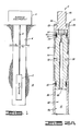
- FIG. 1 is a schematic and block diagram depicting an environment for use in which the preferred embodiment of the present invention is particularly suited;
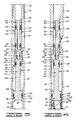
- FIGS. 2A-2C form a longitudinal sectional view of a preferred embodiment of the fluid sampling tool of the present invention, wherein a valve of the tool is in an initial closed position;
- FIG. 3 is a longitudinal sectional view of a portion of the embodiment shown in FIGS. 2A-2C with the valve shown moved to its open, sample-receiving position; and
- FIG. 4 is a longitudinal sectional view of a portion of the embodiment shown in FIGS. 2A-2C with the valve in a subsequent closed position.
- A
fluid sampling tool 2, representing the present invention, is shown in FIG. 1 disposed in an oil or gas well defined by abore 4 which is typically lined with casing (not shown). Thetool 2 is lowered and raised relative to thebore 4 on a slickline 6 which is manipulated byconventional surface equipment 8. The present invention can be used with other types of equipment, such as with a tubing string, or on a wireline, or below a packer as would be readily apparent to those skilled in the art. For the environment depicted in FIG. 1, thetool 2 operates in response to hydrostatic pressure exerted by fluid in thebore 4, which is depicted as intersecting aformation 10. - Another particular environment in which the present invention can be used is in a large sample chamber of a perforate/test sampler tool. This would place the present invention in an atmospheric chamber into which fluid is flowed. In the oil and gas context, such a flow of fluid might first contain a quantity of drilling mud followed by the well fluid from the
formation 10 which is to be sampled. - The structure of the preferred embodiment of the
fluid sampling tool 2 of the present invention will be described with reference to FIGS. 2A-2C, after which the operation of the preferred embodiment will be described with reference to FIGS. 1-4. - The preferred embodiment of the
fluid sampling tool 2 of the present invention, as shown in FIGS. 2A-2C, includes anelongated body 12 with threechambers tool 2 further comprises means 22, disposed in thebody 12 between thechambers chamber 16 to thechamber 18. The preferred embodiment of thetool 2 also includes valve means 24, disposed, as shown in FIG. 2B, in thebody 12 between theport 20 and thechamber 14 such as to be movable relative to thebody 12 in response to pressure acting on the valve means 24 through theport 20, to communicate theport 20 with thechamber 14 only after a predetermined time delay after the pressure begins moving the valve means 24. - Beginning at the top of the orientation in FIG. 2A, the
body 12 includes at one end anend coupling member 26 which defines either the top or the bottom of thetool 2. That is, thetool 2 depicted in FIGS. 2A-2C can be used in either vertical orientation such that the end coupling member is at either the top or bottom of such orientation. Theend coupling member 26 has a plurality ofbores 28 defined in its body for receiving a spanner wrench by which themember 26 can be rotated for coupling and uncoupling to or from threaded connections. One such threaded connection is made at anend 30 to the slickline 6 when thetool 2 is used in the embodiment depicted in FIG. 1. Another such threaded connection is made at an interior threadedsurface 32 of themember 26. This connects themember 26 to anend coupling adapter 34 forming another part of thebody 12. - As illustrated in FIG. 2A, the
end coupling adapter 34 has two threaded pin ends, including the one connected to theend coupling member 26 and another connected to ahousing 36 of thebody 12. Theend coupling adapter 34 also includes a plurality of thebores 28 for receiving a spanner wrench. Axial bores define alongitudinal passageway 38 through theend coupling adapter 34. Seal means 40, including an O-ring 42 andbackup elements 44, are mounted in respective grooves at the two ends of theend coupling adapter 34. - The
housing 36 which is connected to theend coupling adapter 34 and shown in FIGS. 2A-2B is a cylindrical sleeve having aninterior surface 46 which defines acavity 48 that is at least part of thechamber 14. Thechamber 14 of which thecavity 48 forms at least a part is particularly a sample chamber for receiving a fluid sample, such as from the well defined by thebore 4 depicted in FIG. 1. As will be more particularly defined hereinbelow, the sample is received through theport 20 which is defined through the wall of ahousing 50 which is connected at one end to thehousing 36 opposite theend coupling adapter 34. This connection is by mating threaded surfaces forming a joint 52 shown in FIG. 2B. This joint is sealed by another seal means 40. - The
housing 50, shown in FIGS. 2B and 2C, is a cylindrical sleeve having apin end 54 used in forming the joint 52 and also having a threadedbox end 56 opposite theend 54. Thehousing 50 includes aninterior surface 58 defining acavity 60 which communicates with thecavity 48 of thehousing 36 and thus can also define part of thesample chamber 14. Thecavity 60 has a cross-sectional area indicated by theline 62 in FIG. 2B. In the preferred embodiment this cross-sectional area is circular and has a diameter commensurate with theline 62. Theport 20, which can include more than the one opening shown in FIG. 2B, intersects thesurface 58 and communicates the environment exterior of thetool 2 with thecavity 60 so that theport 20 provides an opening in thetool 2 through which pressure and fluid from the well can pass. - The
housing 50 includes aninterior surface 64 extending longitudinally from and spaced radially outwardly from theinterior surface 58 by a radial ortransverse surface 66 shown in FIG. 2B. Thesurface 64 defines acavity 68 which is coaxial with thecavity 60 and which has a cross-sectional area identified by the line 70 in FIG. 2B. The cross-sectional area 70 of the preferred embodiment is circular so that the line 70 also represents a diameter of thecavity 68. As is apparent from FIG. 2B, the cross-sectional area of thecavity 68 is greater than the cross-sectional area of thecavity 60. Thecavity 68 defines at least part of thechamber 16 which in the preferred embodiment is a metering fluid reservoir chamber for receiving a metering fluid, specifically a liquid such as oil of a conventional type as is known to those skilled in the art. - Referring to FIG. 2C, connected to the
box end 56 of thehousing 50 is anadapter member 72 having a threadedpin end 74 connected to thehousing 50 and carrying a seal means 40. Theadapter member 72 also has apin end 76 which carries another seal means 40 and is connected to ahousing 78. Theadapter member 72 and thehousing 78 form additional parts of thebody 12 of the preferred embodiment of the present invention. - The
adapter member 72 has anaxial passageway 80 defined therethrough. Thispassageway 80 communicates with thecavity 68 of thehousing 50 and thus forms another part of thechamber 16 wherein metering fluid is held. Upon operation of the present invention as subsequently described, such metering fluid, or at least a portion thereof, is forced through thepassageway 80 and themeans 22 retained in theend 76 of theadapter member 72 as shown in FIG. 2C. Upon passing through themeans 22, such metering fluid is received in thechamber 18 defined by acavity 82 formed by aninterior surface 84 of thehousing 78. Thechamber 18 defined by thecavity 82 is, in the preferred embodiment, a metering fluid receptacle chamber for receiving metering fluid transferred from the meteringfluid reservoir chamber 16. - The
adapter member 72 and thehousing 78 also include pluralities of thebores 28 for receiving a spanner wrench. - Still referring to FIG. 2C, the
means 22 for impeding fluid flow from thechamber 16 to thechamber 18 is defined in the preferred embodiment by a conventional metering device such as ametering cartridge 86 containing a metering orifice means such as a Visco-Jet element of a type as known to the art. This orifice means prevents fluid flow from thechamber 16 to thechamber 18 until the metering fluid contained in thechamber 16 is placed under sufficient pressure, which occurs when the valve means 24 is pushed by a sufficient pressure acting through theport 20 as will be more fully described hereinbelow. In the preferred embodiment shown in FIG. 2C, themetering cartridge 86 is threadedly connected into thepassageway 80 at theend 76 of theadapter member 72, and themetering cartridge 86 carries one of the sealing O-rings 42. - Referring to FIG. 2B, the preferred embodiment of the valve means 24 will be described. As shown in FIG. 2B, the valve means 24 has parts disposed in both the
cavity 60 and thecavity 68 of thehousing 50. In general, the valve means 24 has three sections referred to herein as first closure means 88, open means 90 and second closure means 92. The first closure means 88 is for maintaining theport 20 sealed from thechamber 14 as the valve means 24 moves relative to theport 20 during the predetermined time delay. The open means, integrally connected to and extending longitudinally from the first closure means 88, is for providing a fluid conducting passageway between theport 20 and thechamber 14 after the predetermined time delay. The second closure means 92, integrally connected to and extending longitudinally from the open means 90, is for sealing theport 20 from thechamber 14 after the open means 90 has moved past theport 20. With these three sections, the valve means 24 is movable through at least a portion of thechamber 16 in response to pressure from the well communicated through theport 20. As the valve means 24 moves, it pushes metering fluid from thechamber 16, through the metering means 22, and into thechamber 18. When this initially occurs during a first time from the time the valve means 24 starts to move and push metering fluid, the valve means 24, by the first closure means 88, seals theport 20 from thechamber 14 for preventing well fluid from entering thechamber 14. Thereafter, during a second time, the valve means 24, by the open means 90, communicates theport 20 with thechamber 14 for allowing a sample of well fluid to be received in thechamber 14. Further thereafter, during a third time, the valve means 24, by the second closure means 92, seals theport 20 from thechamber 14 for holding the sample of well fluid in thechamber 14. A position of the valve means 24 during the aforementioned first time is illustrated in FIG. 2B, a position of the valve means 24 during the aforementioned second time is illustrated in FIG. 3, and a position of the valve means 24 during the aforementioned third time is illustrated in FIG. 4. - Referring again to FIG. 2B, the particular structure of the illustrated preferred embodiment of the valve means 24 will be described. The preferred embodiment valve means 24 is a member which includes an
elongated valve body 94. Thebody 94 has anend 96 disposed in thecavity 68, and thebody 94 has anend 98 disposed in thecavity 60. Theend 96 has a cross-sectional area substantially the same as the cross-sectional area 70, and theend 98 has a cross-sectional area substantially the same as the cross-sectional area 62 ("substantially the same as" means equal to but for tolerances or other design differences whereby the valve means 24 is slidable within thecavities 60, 68). - The
end 96 of thevalve body 94 is identified as a head portion which in the preferred embodiment has a circular cross section with a diameter substantially the same as the diameter also represented by the arrow 70. This head portion includes acircular end surface 100 which is disposed transverse to theelongated body 12 of thetool 2. The head portion also includes a cylindricalouter surface 102 which extends longitudinally from theend surface 100. Acircumferential groove 104 is defined in thesurface 102. The head portion terminates at an annular intermediatetransverse surface 106 which extends inwardly from theouter surface 102. - Extending from the head portion of the
valve body 94 is aneck portion 108 which has a diameter smaller than the diameter of the head portion. It is also smaller than the diameter represented by thearrow 62 shown in FIG. 2B so that anannulus 109 exists between theneck portion 108 andhousing 50. Theneck portion 108 includes a cylindricalouter surface 110 which extends longitudinally from thetransverse surface 106. The length of thesurface 110, and thus of theneck portion 108, is one of the factors to be considered in determining the particular time delay to be implemented in a specific valve. Another factor to be considered is the rate of metering through themeans 22. Thus, the predetermined time delay implemented by the present invention is so predetermined by the metering rate and the length of theneck portion 108. - Extending from the
neck portion 108 is ashoulder portion 112 of thevalve body 94. Theshoulder portion 112 has a cross-sectional area and a diameter smaller than those of the head portion at theend 96 but larger than those of theneck portion 108. The cross-sectional area and the diameter of theshoulder portion 112 are substantially the same as these features identified by thereference numeral 62. Theshoulder portion 112 includes atransverse surface 114 which extends outwardly from theouter surface 110. Theshoulder portion 112 also includes a cylindricalouter surface 116 which extends longitudinally from thetransverse surface 114. Acircumferential groove 118 is defined in thesurface 116. Theshoulder portion 112 terminates at an intermediatetransverse surface 120 which extends inwardly from theouter surface 116. - An
intermediate portion 122 of thevalve body 94 extends from theshoulder portion 112. Theintermediate portion 122 includes a cylindricalouter surface 124 which extends longitudinally from thetransverse surface 120. A plurality ofradial apertures 126 intersect theouter surface 124 and an interior surface 128. The diameter of theintermediate portion 122 is smaller than thediameter 62 so that anannulus 130 is defined between theinterior surface 58 of thehousing 50 and theouter surface 124 of theintermediate portion 122. - Extending longitudinally from the
intermediate portion 122 is theend portion 98 of thevalve body 94. The surface 128 of theintermediate portion 122 extends on through theend portion 98 to anopening 132 which communicates with thechamber 14. Theend portion 98 also includes atransverse surface 134 which extends outwardly from theouter surface 124 of theintermediate portion 122. Theend portion 98 also includes a cylindricalouter surface 136 which extends longitudinally from thetransverse surface 134. Threecircumferential grooves surface 136. Theend portion 98 has a cross-sectional area and diameter substantially the same as those indicated by thereference numeral 62. Theend portion 98 terminates at anannular end surface 144 which extends inwardly from theouter surface 136. Theapertures 126, the interior surface 128 and theopening 132 define apassageway 145 from theintermediate portion 122 through theend portion 98. - The valve means 24 also includes four seal means. A seal means 146 is disposed in the
groove 104 of the head portion at theend 96. This provides a seal between the head portion and theinterior surface 64 of thebody 12. A seal means 148 is disposed in thegroove 118 of theshoulder portion 112 to provide a seal between theshoulder portion 112 and theinterior surface 58 of thebody 12. A seal means 150 is disposed in thegroove 138 of theend portion 98 to provide a seal between the end portion and theinterior surface 58 of thebody 12. A seal means 152 is disposed in thegroove 140 of theend portion 98 to provide a seal between theend portion 98 and theinterior surface 58 of thebody 12. Each of the seal means 146, 148, 150, 152 includes an O-ring (not separately numbered) in sealing contact with the adjacent surface and two backup elements (not separately numbered) of types as are known to the art. - In the preferred embodiment shown in FIGS. 2A-2C, the
tool 2 further comprises frangible means for holding, with a holding force, the valve means 24 relative to theport 20 until pressure from the well communicated through theport 20 exceeds the holding force. The frangible means is represented in the preferred embodiment by frangible shear pins 154 (FIG. 2B) retained inholes 156 defined in theend 54 of thehousing 50. The inner ends of the shear pins 154 are inserted into thecircumferential groove 142 in theend portion 98 of thevalve body 94. The shear pins 154 hold thevalve body 94 stationary relative to theouter body 12 of thetool 2 and theport 20 thereof until pressure above a predetermined magnitude acts on thesurfaces valve body 94. This produces a differential force which is the difference between the pressure from the well exerted on the area of thesurface 106 and pressure from the well exerted on the area of thesurface 114. Because the area of thesurface 106 is greater, the pressure force differential, when large enough, moves thevalve body 94 downwardly as viewed in FIG. 2B. The pressure force differential must exceed the holding force determined by the number and nature of the shear pins 154 before thevalve body 94 begins its movement from the position illustrated in FIG. 2B. - It is to be noted that the shear pins shown in FIG. 2B are needed when the
tool 2 is used in an environment such as the one illustrated in FIG. 1. No shear pins or other equivalent holding means are needed when thetool 2 is used in an environment such as the sample chamber of a perforate/test sampler tool. - The preferred embodiment of the
tool 2 shown in FIGS. 2A-2C still further comprises a movable member 158 (FIG. 2B) disposed in the chamber 14 (specifically thecavity 48 thereof) so that themovable member 158 moves therein in response to thechamber 14 receiving well fluid through theinternal passageway 145 of the valve means 24. Themoveable member 158 is specifically referred to as a piston which is free to move through thecavity 48 between thehousing 50 and theend coupling adapter 34. - Although the foregoing description of the
tool 2 has made particular reference to various elements thereof having cylindrical or circular shapes, the present invention is not limited to any such specific shape or construction. - To describe the operation of the embodiment shown in FIGS. 2A-2C, reference will be made to the environment illustrated in FIG. 1. That is, it will be assumed that the
tool 2 is to take a sample at the bottom of the well defined by thebore 4. It will be assumed that the hydrostatic pressure at such bottom location is believed to be 4000 pounds per square inch psi (27.6 MPa); however, to avoid having to know how accurate the 4000 psi (27.6 MPa) value is, the present invention in the embodiment shown in FIGS. 2A-2C would be used. One or more shear pins 154 would be selected to give a sufficient holding force of some value less than 4000 psi (27.6 MPa) which assuredly exists in the well bore even given the difficulty of knowing the accuracy of the 4000 psi (27.6 MPa) value or precisely where in the bore such lesser pressure exists. For example, 3600 psi (24.8 MPa) might be selected. Thus, the present invention reduces the dependency on knowing precisely what and where well bore pressures are and tolerances of shear pins. - To prepare the
tool 2, metering fluid of a suitable known type is put in thechamber 16. One way to do this would be to remove thehousing 78 and themetering cartridge 86 and pour the fluid through thepassageway 80 of theadapter member 72. After this, thecartridge 86 would be installed and thehousing 78 connected to theadapter member 72. Alternatively, a side fill hole (not shown) could be provided through the side wall of thehousing 50 in communication with thechamber 16. - With the shear pins 154 in place, the metering fluid put in the
chamber 16, and thetool 2 assembled as shown in FIGS. 2A-2C, thetool 2 is lowered into the well with theconventional surface equipment 8. Since no electrical signals need to be transferred between the surface and thetool 2, this lowering can be on a slickline, for example. - As the
tool 2 is being run in the hole or bore 4, the hydrostatic pressure from the fluid within thebore 4 acts on thevalve body 94 between the areas identified by thereference numerals 70 and 62. More specifically, the pressure acts on the area of thesurface 106 and the area of thesurface 114 through the one or more holes of thesample port 20. When the pressure differential applied to these surfaces is sufficient to overcome the holding force of thepins 154, thepins 154 shear or break and the piston-like valve body 94 begins to move downwardly as viewed in FIG. 2B. Thevalve body 94 is prevented from instantly moving its entire travel by the metering means 22. But movement of thevalve body 94 does begin as the metering fluid in thechamber 16 begins to meter through the metering means 22 into thereceptacle chamber 18 which is typically an atmos pheric air chamber. - After the time delay effected by the metering of the
means 22 and the length of theneck portion 108 of the valve means 24, the seal means 148 passes thesample port 20 whereby well fluid flows through thesample port 20 into theannulus 130 and on through thepassageway 145 defined through theintermediate portion 122 and theend portion 98 of the valve body 94 (see FIG. 3). As the well bore fluid enters thechamber 14, pressure remains exerted on thevalve body 94 to continue its downward movement while also pushing thepiston 158 upward as viewed in FIG. 2B. - After a further time period during which the
intermediate portion 122 of thevalve body 94 travels past thesample port 20, the seal means 150 passes thesample port 20 so that the seal means 150, 152 prevent further actuating pressure differentials from acting on thevalve body 94. This also prevents further fluid flow into thechamber 14. This position of thevalve body 94 is illustrated in FIG. 4 wherein theend surface 100 of thevalve body 44 is shown abutting anend surface 160 of theadapter member 72. With thevalve body 94 in this position, thetool 2 can be retrieved to the surface and the collected sample drained and analyzed. - One technique for draining the sample from the
chamber 14 is to remove thehousing 78 and themetering cartridge 86 and then to insert a rod (not shown) to shift thevalve body 94 back to its open position (see FIG. 3) whereby the fluid in thesample chamber 14 can drain through thepassageway 145 in thevalve body 94 and thesample port 20. Thesample chamber 14 can also be purged by pumping fluid through thepassageway 38 of theend coupling adapter 34 and against thepiston 158 to drive thepiston 158 back toward thehousing 50. - Thus, when the
tool 2 is run on a slickline as just described, the shear pins 154 allow thetool 2 to be run in nearly to the bottom of the well before thetool 2 starts to operate. Once thepins 154 are sheared, thetool 2 does not open instantly but is delayed, allowing thetool 2 to be run all the way to bottom prior to collecting a sample. This reduces the dependency on accurate pressure readings and shear pins. - When the
tool 2 is used in a sample chamber of a perforate/test sampler tool, for example, the shear pins 154 need not be used. The delay of the metering system would be sufficient to delay the sampler from opening instantly. This would allow unwanted drilling fluid to bypass theport 20 before it is opened to collect the desired reservoir fluid typically trailing the drilling fluid. - A variety of metering devices and metering fluids and shear pins or other holding mechanisms (when needed) can be used to allow the
tool 2 to operate at different pressures and with different time delays.
Claims (10)
Applications Claiming Priority (2)
| Application Number | Priority Date | Filing Date | Title |
|---|---|---|---|
| US294323 | 1989-01-06 | ||
| US07/294,323 US4903765A (en) | 1989-01-06 | 1989-01-06 | Delayed opening fluid sampler |
Publications (3)
| Publication Number | Publication Date |
|---|---|
| EP0377333A2 true EP0377333A2 (en) | 1990-07-11 |
| EP0377333A3 EP0377333A3 (en) | 1991-10-23 |
| EP0377333B1 EP0377333B1 (en) | 1997-07-23 |
Family
ID=23132912
Family Applications (1)
| Application Number | Title | Priority Date | Filing Date |
|---|---|---|---|
| EP89313686A Expired - Lifetime EP0377333B1 (en) | 1989-01-06 | 1989-12-29 | Delayed opening fluid sampler |
Country Status (6)
| Country | Link |
|---|---|
| US (1) | US4903765A (en) |
| EP (1) | EP0377333B1 (en) |
| AU (1) | AU624889B2 (en) |
| CA (1) | CA2006894C (en) |
| DE (1) | DE68928199T2 (en) |
| NO (1) | NO174939C (en) |
Families Citing this family (46)
| Publication number | Priority date | Publication date | Assignee | Title |
|---|---|---|---|---|
| FR2661943B1 (en) * | 1990-05-10 | 1992-07-17 | Commissariat Energie Atomique | FLUID COLLECTION BOTTLE FOR USE IN DEEP WELLS. |
| US5095745A (en) * | 1990-06-15 | 1992-03-17 | Louisiana State University | Method and apparatus for testing subsurface formations |
| US5184508A (en) * | 1990-06-15 | 1993-02-09 | Louisiana State University And Agricultural And Mechanical College | Method for determining formation pressure |
| US5058674A (en) * | 1990-10-24 | 1991-10-22 | Halliburton Company | Wellbore fluid sampler and method |
| US5103906A (en) * | 1990-10-24 | 1992-04-14 | Halliburton Company | Hydraulic timer for downhole tool |
| FR2671875B1 (en) * | 1991-01-23 | 1993-11-12 | Geostock Sarl | DEVICE AND METHOD FOR COLLECTING AND CONDITIONING GROUNDWATER SAMPLES WITH A VIEW TO DETERMINING IN PARTICULAR THE QUANTITY OF DISSOLVED GAS WHICH THEY CONTAIN, USE IN THE CONTEXT OF A BACTERIAL ANALYSIS. |
| NO172863C (en) * | 1991-05-03 | 1993-09-15 | Norsk Hydro As | ELECTRO-HYDRAULIC DOWN HOLE SAMPLING EQUIPMENT |
| US5240072A (en) * | 1991-09-24 | 1993-08-31 | Halliburton Company | Multiple sample annulus pressure responsive sampler |
| US5375472A (en) * | 1992-05-15 | 1994-12-27 | Mitsubishi Denki Kabushiki Kaisha | Pressure sensor having multiple O-ring sealants provided in series and a fuel tank provided therewith |
| US5261348A (en) * | 1992-09-08 | 1993-11-16 | Qed Environmental Systems, Inc. | Flow-through cell with diverter circuit |
| US5361839A (en) * | 1993-03-24 | 1994-11-08 | Schlumberger Technology Corporation | Full bore sampler including inlet and outlet ports flanking an annular sample chamber and parameter sensor and memory apparatus disposed in said sample chamber |
| US5450900A (en) * | 1993-08-26 | 1995-09-19 | Battelle Memorial Institute | Well fluid isolation and sample apparatus and method |
| US5662166A (en) * | 1995-10-23 | 1997-09-02 | Shammai; Houman M. | Apparatus for maintaining at least bottom hole pressure of a fluid sample upon retrieval from an earth bore |
| FR2741665B1 (en) * | 1995-11-29 | 1998-02-13 | Gaz De France | SAMPLE DEVICE FOR TAKING A FLUID SAMPLE FROM A WELL |
| US5637808A (en) * | 1995-11-30 | 1997-06-10 | Jaeger; Ben E. | Liquid product sampler |
| DE69636665T2 (en) * | 1995-12-26 | 2007-10-04 | Halliburton Co., Dallas | Apparatus and method for early assessment and maintenance of a well |
| US5826662A (en) * | 1997-02-03 | 1998-10-27 | Halliburton Energy Services, Inc. | Apparatus for testing and sampling open-hole oil and gas wells |
| US5887652A (en) * | 1997-08-04 | 1999-03-30 | Halliburton Energy Services, Inc. | Method and apparatus for bottom-hole testing in open-hole wells |
| US6065355A (en) | 1997-09-23 | 2000-05-23 | Halliburton Energy Services, Inc. | Non-flashing downhole fluid sampler and method |
| EP0999348A3 (en) | 1998-11-02 | 2000-11-29 | Halliburton Energy Services, Inc. | Fluid sample chamber with non-reactive lining |
| WO2000050736A1 (en) | 1999-02-25 | 2000-08-31 | Baker Hughes Incorporated | Apparatus and method for controlling well fluid sample pressure |
| US6258324B1 (en) | 1999-03-15 | 2001-07-10 | Felix H. Yiu | Pipette dispensing block |
| NO20004008L (en) | 1999-08-13 | 2001-02-14 | Halliburton Energy Serv Inc | Early evaluation system for lined boreholes |
| RU2244123C2 (en) | 2000-02-25 | 2005-01-10 | Бэйкер Хьюз Инкорпорейтед | Device and method for controlling pressure of well fluid sample |
| NO312689B1 (en) * | 2000-09-05 | 2002-06-17 | Bjoern Dybdahl | Method and apparatus for well testing |
| US6491104B1 (en) | 2000-10-10 | 2002-12-10 | Halliburton Energy Services, Inc. | Open-hole test method and apparatus for subterranean wells |
| US6557632B2 (en) * | 2001-03-15 | 2003-05-06 | Baker Hughes Incorporated | Method and apparatus to provide miniature formation fluid sample |
| US7246664B2 (en) * | 2001-09-19 | 2007-07-24 | Baker Hughes Incorporated | Dual piston, single phase sampling mechanism and procedure |
| US6702024B2 (en) * | 2001-12-14 | 2004-03-09 | Cilmore Valve Co., Ltd. | Dual energized hydroseal |
| US7073590B2 (en) * | 2001-12-14 | 2006-07-11 | Gilmore Valve Co., Ltd. | Dual energized hydroseal |
| US6907797B2 (en) | 2002-11-12 | 2005-06-21 | Baker Hughes Incorporated | Method and apparatus for supercharging downhole sample tanks |
| WO2004099566A1 (en) | 2003-05-02 | 2004-11-18 | Baker Hughes Incorporaated | A method and apparatus for an advanced optical analyzer |
| CN1784536A (en) | 2003-05-02 | 2006-06-07 | 贝克休斯公司 | Continuous data recorder for a downhole sample tank |
| CN100408806C (en) * | 2003-05-21 | 2008-08-06 | 贝克休斯公司 | Method and apparatus for determining an optimal pumping rate based on a downhole dew point pressure determination |
| US7258167B2 (en) * | 2004-10-13 | 2007-08-21 | Baker Hughes Incorporated | Method and apparatus for storing energy and multiplying force to pressurize a downhole fluid sample |
| US8429961B2 (en) * | 2005-11-07 | 2013-04-30 | Halliburton Energy Services, Inc. | Wireline conveyed single phase fluid sampling apparatus and method for use of same |
| US7596995B2 (en) | 2005-11-07 | 2009-10-06 | Halliburton Energy Services, Inc. | Single phase fluid sampling apparatus and method for use of same |
| US7874206B2 (en) * | 2005-11-07 | 2011-01-25 | Halliburton Energy Services, Inc. | Single phase fluid sampling apparatus and method for use of same |
| US7197923B1 (en) | 2005-11-07 | 2007-04-03 | Halliburton Energy Services, Inc. | Single phase fluid sampler systems and associated methods |
| US7472589B2 (en) * | 2005-11-07 | 2009-01-06 | Halliburton Energy Services, Inc. | Single phase fluid sampling apparatus and method for use of same |
| JP5142769B2 (en) * | 2008-03-11 | 2013-02-13 | 株式会社日立製作所 | Voice data search system and voice data search method |
| US7967067B2 (en) | 2008-11-13 | 2011-06-28 | Halliburton Energy Services, Inc. | Coiled tubing deployed single phase fluid sampling apparatus |
| US7926575B2 (en) * | 2009-02-09 | 2011-04-19 | Halliburton Energy Services, Inc. | Hydraulic lockout device for pressure controlled well tools |
| US8506907B2 (en) * | 2010-02-12 | 2013-08-13 | Dan Angelescu | Passive micro-vessel and sensor |
| US9133686B2 (en) | 2011-10-06 | 2015-09-15 | Halliburton Energy Services, Inc. | Downhole tester valve having rapid charging capabilities and method for use thereof |
| AU2011378455B2 (en) | 2011-10-06 | 2015-08-06 | Halliburton Energy Services, Inc. | Downhole tester valve having rapid charging capabilities and method for use thereof |
Citations (3)
| Publication number | Priority date | Publication date | Assignee | Title |
|---|---|---|---|---|
| US3041875A (en) * | 1957-09-30 | 1962-07-03 | Halliburton Co | Surface recording drill stem testing combination |
| US3957117A (en) * | 1974-08-05 | 1976-05-18 | Dale Clarence R | Method and apparatus for bottom hole testing in wells |
| US4787447A (en) * | 1987-06-19 | 1988-11-29 | Halliburton Company | Well fluid modular sampling apparatus |
Family Cites Families (7)
| Publication number | Priority date | Publication date | Assignee | Title |
|---|---|---|---|---|
| US2557925A (en) * | 1948-12-13 | 1951-06-26 | Reed Roller Bit Co | Sampling apparatus |
| US2862561A (en) * | 1954-08-03 | 1958-12-02 | Sun Oil Co | Bottom-hole sampler |
| US3095930A (en) * | 1959-04-27 | 1963-07-02 | Schlumberger Well Surv Corp | Fluid samplers |
| US4372382A (en) * | 1980-12-15 | 1983-02-08 | Texaco Inc. | Method and sampler for collecting a non-pressurized well fluid sample |
| US4502537A (en) * | 1983-09-23 | 1985-03-05 | Halliburton Services | Annular sample chamber, full bore, APR® sampler |
| US4665983A (en) * | 1986-04-03 | 1987-05-19 | Halliburton Company | Full bore sampler valve with time delay |
| US4766955A (en) * | 1987-04-10 | 1988-08-30 | Atlantic Richfield Company | Wellbore fluid sampling apparatus |
-
1989
- 1989-01-06 US US07/294,323 patent/US4903765A/en not_active Expired - Lifetime
- 1989-12-19 NO NO895127A patent/NO174939C/en unknown
- 1989-12-29 DE DE68928199T patent/DE68928199T2/en not_active Expired - Fee Related
- 1989-12-29 CA CA002006894A patent/CA2006894C/en not_active Expired - Fee Related
- 1989-12-29 AU AU47377/89A patent/AU624889B2/en not_active Ceased
- 1989-12-29 EP EP89313686A patent/EP0377333B1/en not_active Expired - Lifetime
Patent Citations (3)
| Publication number | Priority date | Publication date | Assignee | Title |
|---|---|---|---|---|
| US3041875A (en) * | 1957-09-30 | 1962-07-03 | Halliburton Co | Surface recording drill stem testing combination |
| US3957117A (en) * | 1974-08-05 | 1976-05-18 | Dale Clarence R | Method and apparatus for bottom hole testing in wells |
| US4787447A (en) * | 1987-06-19 | 1988-11-29 | Halliburton Company | Well fluid modular sampling apparatus |
Also Published As
| Publication number | Publication date |
|---|---|
| CA2006894A1 (en) | 1990-07-06 |
| EP0377333B1 (en) | 1997-07-23 |
| CA2006894C (en) | 1994-10-18 |
| EP0377333A3 (en) | 1991-10-23 |
| NO174939C (en) | 1994-08-03 |
| DE68928199T2 (en) | 1997-11-13 |
| NO895127L (en) | 1990-07-09 |
| AU4737789A (en) | 1990-07-12 |
| DE68928199D1 (en) | 1997-08-28 |
| US4903765A (en) | 1990-02-27 |
| AU624889B2 (en) | 1992-06-25 |
| NO174939B (en) | 1994-04-25 |
| NO895127D0 (en) | 1989-12-19 |
Similar Documents
| Publication | Publication Date | Title |
|---|---|---|
| EP0377333B1 (en) | Delayed opening fluid sampler | |
| US6065355A (en) | Non-flashing downhole fluid sampler and method | |
| EP0534732B1 (en) | Downhole sampling apparatus | |
| EP0295923B1 (en) | Well fluid sampling apparatus | |
| EP0620893B1 (en) | Formation testing and sampling method and apparatus | |
| EP0347050B1 (en) | Tubing conveyed downhole sampler | |
| US5372193A (en) | Completion test tool | |
| CA1270753A (en) | Full bore sample valve with time delay | |
| US4878538A (en) | Perforate, test and sample tool and method of use | |
| US4883123A (en) | Above packer perforate, test and sample tool and method of use | |
| CA1318241C (en) | Above packer perforate test and sample tool and method of use | |
| EP0511821B1 (en) | Well tool bypass apparatus | |
| EP0615054B1 (en) | Coiled tubing actuated sampler | |
| EP0295922B1 (en) | Downhole tool and method for perforating and sampling | |
| US20040031318A1 (en) | Method and apparatus for determining downhole pressures during a drilling operation |
Legal Events
| Date | Code | Title | Description |
|---|---|---|---|
| PUAI | Public reference made under article 153(3) epc to a published international application that has entered the european phase |
Free format text: ORIGINAL CODE: 0009012 |
|
| AK | Designated contracting states |
Kind code of ref document: A2 Designated state(s): DE ES FR GB IT NL |
|
| PUAL | Search report despatched |
Free format text: ORIGINAL CODE: 0009013 |
|
| AK | Designated contracting states |
Kind code of ref document: A3 Designated state(s): DE ES FR GB IT NL |
|
| 17P | Request for examination filed |
Effective date: 19920304 |
|
| 17Q | First examination report despatched |
Effective date: 19930603 |
|
| APAB | Appeal dossier modified |
Free format text: ORIGINAL CODE: EPIDOS NOAPE |
|
| GRAG | Despatch of communication of intention to grant |
Free format text: ORIGINAL CODE: EPIDOS AGRA |
|
| GRAH | Despatch of communication of intention to grant a patent |
Free format text: ORIGINAL CODE: EPIDOS IGRA |
|
| GRAH | Despatch of communication of intention to grant a patent |
Free format text: ORIGINAL CODE: EPIDOS IGRA |
|
| GRAH | Despatch of communication of intention to grant a patent |
Free format text: ORIGINAL CODE: EPIDOS IGRA |
|
| RAP1 | Party data changed (applicant data changed or rights of an application transferred) |
Owner name: HALLIBURTON ENERGY SERVICES, INC. |
|
| GRAA | (expected) grant |
Free format text: ORIGINAL CODE: 0009210 |
|
| AK | Designated contracting states |
Kind code of ref document: B1 Designated state(s): DE ES FR GB IT NL |
|
| PG25 | Lapsed in a contracting state [announced via postgrant information from national office to epo] |
Ref country code: IT Free format text: LAPSE BECAUSE OF FAILURE TO SUBMIT A TRANSLATION OF THE DESCRIPTION OR TO PAY THE FEE WITHIN THE PRE;WARNING: LAPSES OF ITALIAN PATENTS WITH EFFECTIVE DATE BEFORE 2007 MAY HAVE OCCURRED AT ANY TIME BEFORE 2007. THE CORRECT EFFECTIVE DATE MAY BE DIFFERENT FROM THE ONE RECORDED.SCRIBED TIME-LIMIT Effective date: 19970723 Ref country code: ES Free format text: THE PATENT HAS BEEN ANNULLED BY A DECISION OF A NATIONAL AUTHORITY Effective date: 19970723 |
|
| REF | Corresponds to: |
Ref document number: 68928199 Country of ref document: DE Date of ref document: 19970828 |
|
| ET | Fr: translation filed | ||
| PLBE | No opposition filed within time limit |
Free format text: ORIGINAL CODE: 0009261 |
|
| STAA | Information on the status of an ep patent application or granted ep patent |
Free format text: STATUS: NO OPPOSITION FILED WITHIN TIME LIMIT |
|
| 26N | No opposition filed | ||
| PGFP | Annual fee paid to national office [announced via postgrant information from national office to epo] |
Ref country code: FR Payment date: 19981209 Year of fee payment: 10 |
|
| PGFP | Annual fee paid to national office [announced via postgrant information from national office to epo] |
Ref country code: NL Payment date: 19981229 Year of fee payment: 10 |
|
| PGFP | Annual fee paid to national office [announced via postgrant information from national office to epo] |
Ref country code: GB Payment date: 19981231 Year of fee payment: 10 |
|
| PGFP | Annual fee paid to national office [announced via postgrant information from national office to epo] |
Ref country code: DE Payment date: 19990107 Year of fee payment: 10 |
|
| PG25 | Lapsed in a contracting state [announced via postgrant information from national office to epo] |
Ref country code: GB Free format text: LAPSE BECAUSE OF NON-PAYMENT OF DUE FEES Effective date: 19991229 |
|
| PG25 | Lapsed in a contracting state [announced via postgrant information from national office to epo] |
Ref country code: NL Free format text: LAPSE BECAUSE OF NON-PAYMENT OF DUE FEES Effective date: 20000701 |
|
| GBPC | Gb: european patent ceased through non-payment of renewal fee |
Effective date: 19991229 |
|
| PG25 | Lapsed in a contracting state [announced via postgrant information from national office to epo] |
Ref country code: FR Free format text: LAPSE BECAUSE OF NON-PAYMENT OF DUE FEES Effective date: 20000831 |
|
| NLV4 | Nl: lapsed or anulled due to non-payment of the annual fee |
Effective date: 20000701 |
|
| PG25 | Lapsed in a contracting state [announced via postgrant information from national office to epo] |
Ref country code: DE Free format text: LAPSE BECAUSE OF NON-PAYMENT OF DUE FEES Effective date: 20001003 |
|
| REG | Reference to a national code |
Ref country code: FR Ref legal event code: ST |
|
| APAH | Appeal reference modified |
Free format text: ORIGINAL CODE: EPIDOSCREFNO |