EP0379638A1 - Vorrichtung zur Annahme und Abgabe von Banknoten und Verfahren zu deren Betrieb - Google Patents
Vorrichtung zur Annahme und Abgabe von Banknoten und Verfahren zu deren Betrieb Download PDFInfo
- Publication number
- EP0379638A1 EP0379638A1 EP89116251A EP89116251A EP0379638A1 EP 0379638 A1 EP0379638 A1 EP 0379638A1 EP 89116251 A EP89116251 A EP 89116251A EP 89116251 A EP89116251 A EP 89116251A EP 0379638 A1 EP0379638 A1 EP 0379638A1
- Authority
- EP
- European Patent Office
- Prior art keywords
- banknote
- banknotes
- switch
- delivery
- conveyor
- Prior art date
- Legal status (The legal status is an assumption and is not a legal conclusion. Google has not performed a legal analysis and makes no representation as to the accuracy of the status listed.)
- Granted
Links
Images
Classifications
-
- G—PHYSICS
- G07—CHECKING-DEVICES
- G07D—HANDLING OF COINS OR VALUABLE PAPERS, e.g. TESTING, SORTING BY DENOMINATIONS, COUNTING, DISPENSING, CHANGING OR DEPOSITING
- G07D11/00—Devices accepting coins; Devices accepting, dispensing, sorting or counting valuable papers
- G07D11/0087—Banknote changing devices
-
- G—PHYSICS
- G07—CHECKING-DEVICES
- G07D—HANDLING OF COINS OR VALUABLE PAPERS, e.g. TESTING, SORTING BY DENOMINATIONS, COUNTING, DISPENSING, CHANGING OR DEPOSITING
- G07D11/00—Devices accepting coins; Devices accepting, dispensing, sorting or counting valuable papers
- G07D11/10—Mechanical details
- G07D11/12—Containers for valuable papers
-
- G—PHYSICS
- G07—CHECKING-DEVICES
- G07D—HANDLING OF COINS OR VALUABLE PAPERS, e.g. TESTING, SORTING BY DENOMINATIONS, COUNTING, DISPENSING, CHANGING OR DEPOSITING
- G07D11/00—Devices accepting coins; Devices accepting, dispensing, sorting or counting valuable papers
- G07D11/20—Controlling or monitoring the operation of devices; Data handling
- G07D11/24—Managing the stock of valuable papers
- G07D11/25—Relocation of valuable papers within devices
-
- G—PHYSICS
- G07—CHECKING-DEVICES
- G07D—HANDLING OF COINS OR VALUABLE PAPERS, e.g. TESTING, SORTING BY DENOMINATIONS, COUNTING, DISPENSING, CHANGING OR DEPOSITING
- G07D11/00—Devices accepting coins; Devices accepting, dispensing, sorting or counting valuable papers
- G07D11/20—Controlling or monitoring the operation of devices; Data handling
- G07D11/30—Tracking or tracing valuable papers or cassettes
Definitions
- the invention relates to a device for accepting and delivering banknotes of the type mentioned in the preamble of claim 1.
- Such devices for accepting and delivering banknotes are advantageously used in service machines of all kinds, in particular from the field of banking and exchange offices.
- a device for accepting and delivering banknotes of the type mentioned in the preamble of claim 1 is known from DE-PS 35 19 607 and has a predetermined number of storage containers for banknotes, each storage container containing only banknotes of a single value level.
- the banknotes are only checked with a tester when they are accepted. When dispensing, the banknotes are removed from the corresponding storage containers, bundled in a stacking wheel and dispensed to a user of the device in a bundle.
- a device for accepting and delivering banknotes has a single test device for the acceptance and delivery control of the banknotes, and it has separate cash registers for the acceptance and delivery of banknotes.
- the dispenser comprises a predetermined number of storage containers, each of which contains only banknotes of a single value level.
- a test device is known from US Pat. No. 4,319,137 which determines the authenticity and the orientation of a banknote by means of optical scanning of the printed image.
- the banknote in the reading plane of the testing device only has to be oriented according to the outer shape, a certain lateral offset being electronically compensated for.
- the result of the scan is compared to patterns from a predetermined set of value levels.
- the banknotes are transported by means of endless belts.
- CH application 00 057 / 89-9 describes a device for turning and rotating banknotes in order to bring them into a predetermined orientation for stacking.
- the invention has for its object to provide a device that automatically takes banknotes of different value levels and dimensions, controls and stores or delivers them to a user, and to specify a method for their operation.
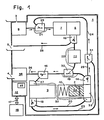
- Fig. 1, 1 means a device for the machine acceptance and delivery of banknotes 2 of different value levels (different denominations of at least one currency), 3 an input opening, 4 a delivery opening, 5 a return tray, 6 a separator, 7 a straightening section, 8 a test device , 9 a first cash register, 10 a second cash register and 11 a turning device.
- a control device 12 is connected by means of lines (not shown here for the sake of illustration) to devices of the device 1, for example to the test device 8, to a banknote store described below, to a first and a second checkout switch 13 and 14, with a delivery switch 15 and with a return switch 16.
- Each switch 13 to 16 has a drive device influenced by the control device 12, e.g. B. an electric motor, an electric magnet, etc., which changes the path of the banknote 2 in each of the switches 13 to 16 from the entrance to one of the two branches.
- the control device 12 selects one of the predetermined routes for the banknote 2 as a function of the signals and information it receives, and for this purpose brings the routes of the switches 13 to 16 into a predetermined position.
- Sensors (not shown here) of the control device 12 are used to monitor sections of the route and to control drive motors (not shown here) of a transport system of the device 1.
- the drive motors are switched on or off by the control 12 as required and are in normal operation except in the turning device 11 the direction of rotation cannot be reversed.
- the control device 12 also exchanges information via a two-way data line 17 with further apparatuses 18, which are represented symbolically with a single rectangle. Some of the apparatuses 18 are either set up separately or are also housed in the same housing as the device 1.
- the transport system of the device 1 comprises a first conveyor belt 19, a second conveyor belt 20, a conveyor section 21, a transport section 22, a belt conveyor 23, a conveyor 24, a connecting section 25, a delivery section 26, a conveyor belt 27 and a return section 28 Because of the clarity of the drawing, they are only indicated with a broad line. Arrows parallel to these lines indicate where necessary the direction of transport for clarification.
- the transport system also includes switches 13 to 16 and three junctions 29 to 31.
- the aforementioned banknote store contains the banknotes 2 of all predetermined value levels which have been accepted by the device 1 and can be called up for delivery.
- it is composed of the two cash registers 9 and 10, the cash register switches 13 and 14, the second conveyor belt 20, the belt conveyor 23, the connecting line 25 and the third junction 31.
- Each till 9 or 10 has a till entrance 32, a till head 33 and the till switch 13 or 14 at the exit.
- a mechanism (not shown) in each checkout head 33 places the banknote 2 arriving through the checkout entrance 32 on a checkout stack 34.
- a spring presses the cash register stack 34 against the mechanism in the cash register head 33 so that it can pick up the uppermost bank note 2 from the cash register stack 34 and insert it into the entrance of the cash register switch 13 or 14. Only in the case of the second cash register 10 shown schematically in section is the cash register head 33 and the cash register stack 34 provided with the reference number.
- the transport system consists of an arrangement of endless, parallel belts, which are guided over rollers, cylinders, guide plates, the drive motors and other elements known from conveyor technology.
- the cylinders and rollers all rotate about axes that are, for example, perpendicular to the plane of the drawing in FIGS. 1 to 3.
- the transport system conveys sheet-like goods having dimensions from a predetermined range, such as. B. banknotes 2 different value levels.
- the material clamped between pairs of belts or between belts and a cylinder is fed from the input opening 3 via the test device 8 to an input of the banknote store, from an outlet of the banknote store via the test device 8 to the delivery opening 4, from the test device 8 to the return tray 5 or from the exit of the banknote store transported to its entrance.
- the conveyor section 21 leads from the separator 6, which is arranged directly behind the input opening 3, through the first junction 29 and the straightening section 7 to the test device 8.
- An output of the test device 8 opens into the input of the return switch 16.
- the transport path 22 connects a branch of the return switch 16 via the turning device 11 to the one input of the second junction 30, while a second branch of the return switch 16 leads via the return path 28 to the return tray 5 .
- a branch of each checkout gate 13 or 14 of the one checkout 9 or 10 is connected to the checkout entrance 32 of the other checkout 10 or 9 by means of the conveyor belt 20 or by means of the belts 19 and 27.
- the belt conveyor 23 and the connecting section 25 form the other two branches of the checkouts 13 and 14. They lead through the two entrances into the third mouth 31 to the conveyor 24. It extends from the exit of the third mouth 31 to an entrance of the first mouth 29
- the first junction 29 enables the banknotes 2 to be introduced from the conveyor 24 into the conveyor section 21, which transports the sheet-like material through the straightening section 7 to the checking device 8.
- the first conveyor track 19 leads through the second opening 30, where the transport route 22 opens into the first conveyor track 19 in the direction of the first cash register 9.
- the end of the first conveyor track 19 forms the delivery diverter 15, one branch of which opens as a conveyor belt 27 into the cash register entrance 32 of the first cash register 9 and the other branch, referred to as the delivery section 26, is connected to the delivery opening 4.
- a user of the device 1 removes z. B. a writing board, which types of banknotes 2 the device 1 recognizes. The user inserts one or more of these banknotes 2 into the return tray 5, which only need to be aligned with the outer shape.
- the banknotes 2 may be wildly mixed and, for example, comprise different value levels and / or issues from different banknotes.
- the device 1 is therefore used as a note changer z. B. in border areas or in international airports and train stations, where notes from other countries are often in circulation.
- the separator 6 Upon a command from the control device 12, the separator 6 detects, for example, the lowest banknote 2 in the input opening 3 and introduces it into the conveyor path 21.
- the bank note 2 reaches the straightening section 7 via the first junction 29.
- the straightening section 7, for example, aligns the long sides of the bank note 2 exactly parallel to the conveying direction of the transport section 21 and forwards the aligned bank note 2 to the checking device 8.
- the separator 6 also introduces this into the conveyor line 21.
- the checking device 8 optically and / or magnetically scans a printed image on at least one side of the bank note 2.
- the recorded pattern is electronically compared with a predetermined set of stored images of the banknotes 2 to be accepted, the checking device 8 determining the value unit, the type of banknote 2 and its orientation.
- Damaged, unidentifiable or incorrect banknotes 2 as well as value levels not belonging to the predetermined set are classified as unidentifiable goods like unprinted paper of suitable size.
- the length and the width of the bank note 2 are also advantageously determined, since this information severely limits the number of value levels to be recognized by the device 1 and belonging to the predetermined set and thus accelerates the determination of the type of bank note.
- a further advantageous shortening of the test time for a bank note 2 is achieved if the test device 8, which scans the bank note 2 using both methods, decides on the basis of these measurements whether only the result of the optical or magnetic scanning is evaluated.
- test device 8 monitors the sheet thickness of the transported goods, which is measured, for example, mechanically or by means of an optical determination of the transparency of the bank note 2. Monitoring the sheet thickness prevents two or more banknotes 2 lying on one another from being accepted.
- Each test result is transmitted to the control device 12 in a value signal.
- the value signal for the goods determines the route in the transport system of the device 1 and the destination.
- the non-identifiable goods are passed via the delivery switch 16 into the return section 28, which transports them into the return tray 5.
- the control device 12 credits the user with a credit corresponding to the value of the accepted banknote 2. For example, this credit can be displayed using one of the apparatuses 18.
- the control device 12 directs this bank note 2 into the transport path 22 by means of the return switch 16. Under the control of the control device 12, the turning device 11 brings the bank note 2 into the predetermined position for storage. At the end of the transport route 22, the banknote 2 is introduced into the first conveyor belt 19 by means of the second junction 30 and from there is conveyed from there by means of the delivery diverter 15 via the conveyor belt 27 through the till entrance 32 into the till head 33 of the first till 9. The mechanism in the cash register head 33 places the bank note 2 on top of the cash stack 34.
- control device 12 decides on the further procedure in accordance with the instructions received via the two-way data line 17.
- the device 1 can use one of the apparatuses 18 to give the user a receipt for paid money and the amount paid in according to the display credit his account, the number of which has been entered on a keyboard (not shown here) of one of the devices 18.
- the user can also use the device 1 to withdraw an amount from his account or exchange the banknotes 2 entered through the input opening 3 for others.
- the device 1 for payment can receive banknotes 2, initiate the service and deliver any note portion of the change.
- the device 1 is connected to a further apparatus 18, which is designed as a coin dispenser and which transfers the remaining portion of the calculated change to the user.
- the mechanism in the cash register head 33 of the second cash register 10 inserts the uppermost bank note 2 of the cash register stack 34 into the cash register switch 14.
- This bank note 2 is fed to the testing device 8 via the connecting section 25 and the conveyor 24. If the bank note 2 has a value level intended for delivery, the switches 16 and 15 guide the bank note 2 into the delivery path 26 when it is removed from the test device 8. On the other hand, if the bank note 2 does not belong to any of these value levels intended for delivery, the bank note becomes 2 returned to the first cash register 9 by means of the switches 16 and 15. This process of stacking is continued until all the value stages provided for the delivery have been introduced into the delivery section 26.
- the advantage of this stacking method is shown in a simple and inexpensive embodiment of the device 1, since only a single banknote store is required to store entered banknotes 2 of a predetermined set of value levels and / or to deliver banknotes 2 of predetermined value levels.
- the unsuitable banknote 2 is retrieved from the first cash register 9 and fed to the testing device 8 via the belt conveyor 23 and via the conveyor 24, this banknote 2 becomes the first through the cash register entrance 32 and through the cash register head 33
- the checkout 9 is transported through to the first checkout gate 13 and then fed via the second conveyor belt 20 through the checkout entrance 32 to the second checkout 10, where the banknote 2 is deposited on the checkout stack 34 by the mechanism of the checkout head 33.
- the value signal and a code number which determines the position of the bank note in the bank note memory with respect to the other bank notes 2 of the cash stack 34 are advantageously written into or deleted in a memory part 35 of the control device 12 , as well as the code numbers for all banknotes that remain in the banknote storage.
- the control device 12 searches the storage part 35 and, based on the registered sequence of the value levels, determines from which till 9 or 10 the banknotes are taken.
- the uppermost banknote 2 on the cash register stack 34 of the cash register 9 or 10 selected by the control device 12 is unsuitable, then this banknote 2 is returned directly to the cash register stack 34 in the other cash register via the conveyor belt 20 or via the belts 19 and 27 10 or 9 filed. If necessary, after a few repetitions of this process, a bank note 2 predetermined for delivery is exposed as the topmost of the cash stack 34, which is fed to the checking device 8. On the other hand, the impossibility of the desired transaction can also be displayed to the user if the cash registers 9 and 10 contain no or too little of the required value levels of the desired bank notes 2.
- the banknote store has a capacity of a few thousand banknotes 2, which corresponds to the maximum size of a single cash stack 34. In an extreme case, after the entire stack of banknotes 2 has been stacked to expose a suitable value level, the entire contents of the banknote store can be contained in a single cash stack 34.
- the control device 12 receives for example, the command from one of the apparatuses 18 to pay out a predetermined amount.
- the control device 12 advantageously optimizes the dispensing in such a way that as few banknotes 2 as possible have to be dispensed from the cash registers 9 and 10, the dispensing taking place from the cash register 9 or 10, with the least possible banknotes 2 have to be moved from one cash register 9 or 10 to another 10 or 9. It is also conceivable to enter the desired denomination of the amount to be dispensed using the keyboard of the apparatus 18.
- the control device 12 decides whether banknotes 2 have to be moved between the checkouts 9 and 10 in such a way that approximately the same number of banknotes in the two checkouts 9 and 10 2 are included.
- the delivery section 26 therefore ends in a stacker 36. It collects the banknotes 2 arriving and to be issued one after the other and delivers them to the user through the delivery opening 4 in one batch.
- the initial equipping of the banknote store on banknotes 2 is composed of different portions of the value levels.
- the control device 12 advantageously maintains statistics on the number and type of banknotes received and dispensed 2. When the device 1 is checked, it can therefore be determined whether the composition of the cash stack 34 is optimal or whether the proportion of certain value levels in the banknote store has to be increased .
- Another advantage over the prior art is the extension of the time between the checks of the device 1, since the banknotes 2 taken are stored in the banknote store and are available again for dispensing, in particular if the dispensing is in this way It is optimized that the disproportionately represented value levels are given preferentially.
- the return switch 16, the return path 28 and the return tray 5 are missing.
- the unidentified goods may then only be passed from the control device 12 to the delivery opening 4 when banknotes 2 are entered, but not when they are released from the banknote store.
- the turning device 11 is omitted. This simplification is purchased with a higher expenditure of time when issuing notes, since the test device 4 also has to determine the orientation of the bank note 2 during the delivery.
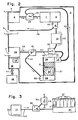
- the device 1 in FIG. 2 is equipped with a simplified transport system and another banknote storage device.
- the transport system of the device 1 comprises only the switches 14 to 16, the conveyor belt 19, the conveyor section 21, the transport section 22, the conveyor 24, the discharge section 26, the conveyor belt 27, the return section 28 and the openings 29 and 30.
- the second checkout switch 13 the third Junction 31 and the sections 20, 23 and 25 of the transport system.
- the banknote store consists of only a single "first in - first out" cash register (FIFO cash register) 37 (FIG. 2).
- the only stack of cash registers 34 in the FIFO cash register 37 is delimited at the cash register entrance 32 from below by a depositing device 38 and on the upper side by a removal device 39.
- the removal device 39 has the only checkout switch 14 on the output side.
- the content of the banknote store, i.e. H. the height of the cash stack 34 determines the distance between the depositing device 38 and the removal device 39.
- the depositing device 38 is pressed, for example, by spring force onto the cash stack 34 against the removal device 39.
- the checkout switch 14 is connected to the conveyor belt 19 via one branch.
- the other branch opens directly into the conveyor 24, which establishes the connection to the test device 8.
- the delivery switch 15 is connected with one branch to the delivery line 26.
- the other branch, the conveyor belt 27, leads to the cash register entrance 32 and has a compensating piece at the cash register end. It adapts to the changing position of the cash register entrance 32, which is determined by the different height of the cash register stack 34.
- a bank note 2 is conveyed into the FIFO cash register 37 via the conveyor belt 27 and is deposited as the lowest in the cash register stack 34 by the depositing device 38.
- the removal device 39 removes the uppermost bank note 2 from the cash stack 34 on a command from the control device 12 and introduces it into the cash switch 14.
- the bank note 2 is sent to the conveyor 24 or via the checkout switch 14 the conveyor belt 19 delivered. If the value level of the uppermost banknote 2 does not match the predetermined value level, the banknotes 2 must be redirected via the conveyor belt 19 and the conveyor belt 27 for stacking until this requirement is met.
- the advantage of the simplified and less expensive banknote storage must be bought with an on average slightly longer delivery time, since the entire contents of the banknote storage may have to be rearranged until the predetermined value level can be released.
- an additional switch 40 is installed at the end of the transport path 22 after the turning device 11 (FIG. 3), one branch of which opens into a container for banknotes 2, which the checking device 8 recognizes, but the device 1 z. B. does not deliver as a foreign currency, and the other branch leads instead of the transport route 22 via the second junction 30 to the conveyor belt 19.
- the container is advantageously designed as a sorting device 41 with a plurality of stacking compartments 42, in order to deposit the banknotes 2 in a predetermined orientation, arranged according to value levels.
- the additional switch 40 and the sorting device 41 are connected to the control device 12 (FIG. 1) via lines (not shown here).
- the control device 12 also decides, for example, on the basis of the content of its storage part 35, at what point in time which banknotes 2 are removed from the banknote store and stored in the predetermined stacking compartments 42 (FIG. 3), so that the banknote store is not clogged by too many banknotes of the same value level.
- the advantages of a device 1 according to FIG. 3 lie in the longer period between the checks, in a permanently optimized content of the banknote store and in the bundles of banknotes 2 which are stored in the stacking compartments 42 with a predetermined orientation.
Abstract
Description
- Die Erfindung bezieht sich auf eine Vorrichtung zur Annahme und Abgabe von Banknoten der im Oberbegriff des Anspruchs 1 genannten Art.
- Solche Vorrichtungen zur Annahme und Abgabe von Banknoten werden vorteilhaft in Dienstleistungsautomaten aller Art, insbesondere aus dem Bereich des Bank- und Wechselstubenwesens, verwendet.
- Eine Vorrichtung zur Annahme und Abgabe von Banknoten der im Oberbegriff des Anspruchs 1 genannten Art ist aus der DE-PS 35 19 607 bekannt und weist eine vorbestimmte Zahl von Vorratsbehältern für Banknoten auf, wobei jeder Vorratsbehälter nur Banknoten einer einzigen Wertstufe enthält. Die Banknoten werden mittels eines Prüfgeräts nur bei der Annahme geprüft. Bei der Abgabe werden die Banknoten den entsprechenden Vorratsbehältern entnommen, in einem Stapelrad gebündelt und in einem Bündel einem Benutzer der Vorrichtung abgegeben.
- Weiter ist aus der DE-PS 32 22 689 eine Vorrichtung zur Annahme und Abgabe von Banknoten bekannt. Sie weist ein einziges Prüfgerät für die Annahme- und Abgabekontrolle der Banknoten auf, wobei sie getrennte Kassen für die Annahme und Abgabe von Banknoten aufweist. Die Abgabekasse umfasst eine vorbestimmte Zahl der Vorratsbehälter, von denen jeder nur Banknoten einer einzigen Wertstufe enthält.
- Aus der US-PS 4 319 137 ist ein Prüfgerät bekannt, das die Echtheit und die Orientierung einer Banknote mittels optischer Abtastung des Druckbildes feststellt. Die Banknote muss in der Leseebene des Prüfgeräts nur nach der äusseren Form orientiert sein, wobei ein gewisser lateraler Versatz elektronisch ausgeglichen wird. Das Resultat der Abtastung wird mit Mustern aus einem vorbestimmten Satz von Wertstufen verglichen. Die Banknoten werden mittels endloser Bänder transportiert.
- Aus der CH-PS 662 194 ist auch eine magnetische Abtastung des Druckbildes einer Banknote bekannt, die die magnetischen Eigenschaften bestimmter Druckfarben ausnützt.
- Die CH-Anmeldung 00 057/89-9 beschreibt eine Vorrichtung zum Wenden und Drehen von Banknoten, um sie für das Stapeln in eine vorbestimmte Orientierung zu bringen.
- Der Erfindung liegt die Aufgabe zugrunde, eine Vorrichtung zu schaffen, die maschinell Banknoten verschiedener Wertstufen und Abmessungen einnimmt, kontrolliert und speichert oder an einen Benutzer abgibt, sowie ein Verfahren zu deren Betrieb anzugeben.
- Die genannte Aufgabe wird erfindungsgemäss durch die Merkmale der Ansprüche 1 und 8 gelöst.
- Nachfolgend werden Ausführungsbeispiele der Erfindung anhand der Zeichnungen näher erläutert.
- Es zeigt:
- Fig. 1 eine Ausführung der Vorrichtung mit zwei Kassen im Schema,
- Fig. 2 eine andere Ausführung mit einer Kasse und
- Fig. 3 eine Zusatzausrüstung für die Vorrichtung nach einer der Figuren 1 und 2.
- In der Fig. 1 bedeutet 1 eine Vorrichtung zur maschinellen Annahme und Abgabe von Banknoten 2 verschiedener Wertstufen (verschiedene Nennwerte wenigstens einer Währung), 3 eine Eingabeöffnung, 4 eine Abgabeöffnung, 5 eine Rückgabeschale, 6 einen Separator, 7 eine Richtstrecke, 8 ein Prüfgerät, 9 eine erste Kasse, 10 eine zweite Kasse und 11 eine Wendevorrichtung.
- Eine Steuereinrichtung 12 ist mittels hier aus darstellerischen Gründen nicht gezeigten Leitungen mit Geräten der Vorrichtung 1 verbunden, beispielsweise mit dem Prüfgerät 8, mit einem weiter unten beschriebenen Banknotenspeicher, mit einer ersten und einer zweiten Kassenweiche 13 und 14, mit einer Abgabeweiche 15 und mit einer Rückgabeweiche 16.
- Jede Weiche 13 bis 16 weist eine von der Steuereinrichtung 12 beeinflusste Antriebseinrichtung auf, wie z. B. einen Elektromotor, einen Elektrozugmagneten usw., die den Laufweg der Banknote 2 in jeder der Weichen 13 bis 16 von deren Eingang zu einem der beiden Zweige umstellt. Die Steuereinrichtung 12 wählt in Abhängigkeit der von ihr empfangenen Signale und Informationen einen der vorbestimmten Wege für die Banknote 2 aus und bringt dazu die Laufwege der Weichen 13 bis 16 in eine vorbestimmte Stellung.
- Hier nicht gezeigte Sensoren der Steuereinrichtung 12 dienen der Ueberwachung von Streckenabschnitten und der Steuerung von hier nicht gezeigten Antriebsmotoren eines Transportsystems der Vorrichtung 1. Die Antriebsmotoren werden von der Steuerung 12 nach Bedarf ein- oder ausgeschaltet und sind ausser in der Wendevorrichtung 11 im normalen Betrieb in der Laufrichtung nicht umsteuerbar.
- Die Steuereinrichtung 12 tauscht auch Informationen über eine Zweiwegdatenleitung 17 mit weiteren Apparaten 18 aus, die symbolisch mit einem einzigen Rechteck dargestellt sind. Einige der Apparate 18 sind entweder separat aufgestellt oder auch im gleichen Gehäuse wie die Vorrichtung 1 untergebracht.
- Das Transportsystem der Vorrichtung 1 umfasst in einer Ausführung ein erstes Förderband 19, ein zweites Förderband 20, eine Förderstrecke 21, eine Transportstrecke 22, einen Bandförderer 23, einen Förderer 24, eine Verbindungsstrecke 25, eine Abgabestrecke 26, ein Transportband 27 und eine Rückgabestrecke 28. Sie sind in der Zeichnung der Uebersichtlichkeit wegen nur mit einem breiten Strich angedeutet. Pfeile parallel zu diesen Strichen geben, wo nötig, zur Verdeutlichung die Transportrichtung an. Zum Transportsystem gehören auch die Weichen 13 bis 16 und drei Einmündungen 29 bis 31.
- Der erwähnte Banknotenspeicher enthält die Banknoten 2 aller vorbestimmten Wertstufen, die von der Vorrichtung 1 angenommen wurden und für eine Abgabe abrufbar sind. In einer ersten Ausführung setzt er sich aus den zwei an sich identischen Kassen 9 und 10, den Kassenweichen 13 und 14, dem zweiten Förderband 20, dem Bandförderer 23, der Verbindungsstrecke 25 und der dritten Einmündung 31 zusammen. Jede Kasse 9 bzw. 10 weist einen Kasseneingang 32, einen Kassenkopf 33 und die Kassenweiche 13 bzw. 14 am Ausgang auf. Eine nicht gezeigte Mechanik in jedem Kassenkopf 33 legt die durch den Kasseneingang 32 ankommende Banknote 2 auf einem Kassenstapel 34 ab. Eine Feder beispielsweise drückt den Kassenstapel 34 gegen die Mechanik im Kassenkopf 33, damit diese die oberste Banknote 2 vom Kassenstapel 34 aufnehmen und in den Eingang der Kassenweiche 13 bzw. 14 einführen kann. Nur bei der schematisch im Schnitt dargestellten zweiten Kasse 10 ist der Kassenkopf 33 und der Kassenstapel 34 mit der Bezugszahl versehen.
- Das Transportsystem setzt sich aus einer Anordnung von endlosen, parallel geführten Riemen, die über Rollen geführt sind, Zylindern, Leitblechen, den Antriebsmotoren sowie weiteren aus der Fördertechnik bekannten Elementen zusammen. Die Zylinder und Rollen drehen sich alle um Achsen, die beispielsweise senkrecht zur Zeichnungsebene in den Figuren 1 bis 3 stehen.
- Das Transportsystem befördert blattförmige Güter, die Abmessungen aus einem vorbestimmten Bereich aufweisen, wie z. B. Banknoten 2 verschiedener Wertstufen. Das zwischen paarweise angeordneten Riemen oder zwischen Riemen und einem Zylinder eingeklemmte Gut wird von der Eingabeöffnung 3 über das Prüfgerät 8 zu einem Eingang des Banknotenspeichers, von einem Ausgang des Banknotenspeichers über das Prüfgerät 8 zur Abgabeöffnung 4, vom Prüfgerät 8 zur Rückgabeschale 5 oder vom Ausgang des Banknotenspeichers zu dessen Eingang transportiert.
- Die Förderstrecke 21 führt vom Separator 6, der unmittelbar hinter der Eingabeöffnung 3 angeordnet ist, durch die erste Einmündung 29 und die Richtstrecke 7 hindurch zum Prüfgerät 8.
- Ein Ausgang des Prüfgeräts 8 mündet in den Eingang der Rückgabeweiche 16. Die Transportstrecke 22 verbindet einen Zweig der Rückgabeweiche 16 über die Wendevorrichtung 11 mit dem einen Eingang der zweiten Einmündung 30, während ein zweiter Zweig der Rückgabeweiche 16 über die Rückgabestrecke 28 zur Rückgabeschale 5 führt.
- Ein Zweig jeder Kassenweiche 13 bzw. 14 der einen Kasse 9 bzw. 10 ist mittels des Förderbandes 20 bzw. mittels der Bänder 19 und 27 mit dem Kasseneingang 32 der andern Kasse 10 bzw. 9 verbunden. Der Bandförderer 23 und die Verbindungsstrecke 25 bilden die beiden anderen Zweige der Kassenweichen 13 und 14. Sie führen durch die beiden Eingänge in die dritte Einmündung 31 zum Förderer 24. Er erstreckt sich vom Ausgang der dritten Einmündung 31 bis zu einem Eingang der ersten Einmündung 29. Die erste Einmündung 29 ermöglicht das Einführen der Banknoten 2 aus dem Förderer 24 in die Förderstrecke 21, die das blattförmige Gut durch die Richtstrecke 7 zum Prüfgerät 8 transportiert.
- Die erste Förderbahn 19 führt durch die zweite Einmündung 30 hindurch, wo die Transportstrecke 22 in der Richtung zur ersten Kasse 9 hin in die erste Förderbahn 19 einmündet. Das Ende der ersten Förderbahn 19 bildet die Abgabeweiche 15, deren einer Zweig als Transportband 27 in den Kasseneingang 32 der ersten Kasse 9 mündet und deren anderer Zweig, als Abgabestrecke 26 bezeichnet, mit der Abgabeöffnung 4 verbunden ist.
- Ein Benutzer der Vorrichtung 1 entnimmt z. B. einer Schrifttafel, welche Arten von Banknoten 2 die Vorrichtung 1 erkennt. Der Benutzer legt in die Rückgabeschale 5 eine oder mehrere dieser Banknoten 2 ein, die lediglich nach der äusseren Form ausgerichtet sein müssen. Die Banknoten 2 dürfen wild gemischt sein und beispielsweise verschiedene Wertstufen und/oder Ausgaben verschiedener Noteninstitute umfassen. Die Vorrichtung 1 ist demnach als Notenwechsler verwendbar z. B. in grenznahen Gebieten oder in internationalen Flughäfen und Bahnhöfen, wo häufig Noten anderer Länder im Umlauf sind.
- Auf ein Kommando der Steuereinrichtung 12 erfasst der Separator 6 beispielsweise die unterste Banknote 2 in der Eingabeöffnung 3 und führt sie in die Förderstrecke 21 ein. Ueber die erste Einmündung 29 gelangt die Banknote 2 in die Richtstrecke 7. Die Richtstrecke 7 richtet beispielsweise die Längsseiten der Banknote 2 genau parallel zur Förderrichtung der Transportstrecke 21 aus und gibt die ausgerichtete Banknote 2 an das Prüfgerät 8 weiter. Sobald die Förderstrecke 21 frei ist und sich in der Eingabeöffnung 3 wenigstens eine weitere Banknote 2 befindet, führt der Separator 6 auch diese in die Förderstrecke 21 ein.
- Das Prüfgerät 8 tastet optisch und/oder magnetisch ein Druckbild auf wenigstens einer Seite der Banknote 2 ab. Das aufgenommene Muster wird mit einem vorbestimmten Satz gespeicherter Abbilder der anzunehmenden Banknoten 2 elektronisch verglichen, wobei das Prüfgerät 8 die Werteinheit, die Art der Banknote 2 und deren Orientierung feststellt.
- Beschädigte, nichtidentifizierbare oder falsche Banknoten 2 sowie nicht dem vorbestimmten Satz zugehörige Wertstufen werden gleich wie unbedrucktes Papier passender Grösse als nichtidentifizierbares Gut klassiert.
- Vorteilhaft werden auch die Länge und die Breite der Banknote 2 bestimmt, da diese Information die Anzahl der von der Vorrichtung 1 zu erkennenden, dem vorbestimmten Satz zugehörigen Wertstufen stark einschränkt und so die Bestimmung der Banknotenart beschleunigt. Eine weitere vorteilhafte Verkürzung der Prüfzeit für eine Banknote 2 gelingt, wenn das Prüfgerät 8, das die Banknote 2 nach beiden Verfahren abtastet, auf grund dieser Messungen entscheidet, ob nur das Ergebnis der optischen oder der magnetischen Abtastung ausgewertet wird.
- Eine andere Ausführung des Prüfgeräts 8 überwacht die Blattdicke des transportierten Guts, die beispielsweise auf mechanische Art oder mittels einer optischen Bestimmung der Transparenz der Banknote 2 gemessen wird. Die Ueberwachung der Blattdicke verhindert, dass zwei oder mehrere aufeinander liegende Banknoten 2 angenommen werden.
- Jedes Prüfergebnis wird der Steuereinrichtung 12 in einem Wertesignal übermittelt. In der Steuereinrichtung 12 bestimmt das Wertesignal für das Gut den Laufweg im Transportsystem der Vorrichtung 1 und den Zielort.
- Das nichtidentifizierbare Gut wird über die Abgabeweiche 16 in die Rückgabestrecke 28 geleitet, die es in die Rückgabeschale 5 transportiert.
- Wird eine als echt erkannte Banknote 2 einer vorbestimmten Wertstufe von der Vorrichtung 1 angenommen, schreibt die Steuereinrichtung 12 dem Benutzer ein dem Wert der angenommen Banknote 2 entsprechendes Haben gut. Beispielweise kann dieses Guthaben mittels eines der Apparate 18 zur Anzeige gebracht werden.
- Die Steuereinrichtung 12 lenkt diese Banknote 2 mittels der Rückgabeweiche 16 in die Transportstrecke 22. Die Wendevorrichtung 11 bringt unter der Kontrolle der Steuereinrichtung 12 die Banknote 2 in die für die Speicherung vorbestimmte Lage. Am Ende der Transportstrecke 22 wird die Banknote 2 mittels der zweiten Einmündung 30 in das erste Förderband 19 eingeschleust und von dort mittels der Abgabeweiche 15 über das Transportband 27 durch den Kasseneingang 32 in den Kassenkopf 33 der ersten Kasse 9 befördert. Die Mechanik im Kassenkopf 33 legt die Banknote 2 zuoberst auf dem Kassenstapel 34 ab.
- Sind alle Banknoten 2 aus der Eingabeöffnung 3 in der ersten Kasse 9 abgelegt, entscheidet die Steuereinrichtung 12 gemäss der über die Zweiwegdatenleitung 17 empfangenen Instruktionen über das weitere Vorgehen.
- Beispielsweise kann die Vorrichtung 1 mittels eines der Apparate 18 dem Benutzer eine Quittung über einbezahltes Geld aushändigen und den einbezahlten Betrag gemäss der Anzeige seinem Konto gutschreiben, dessen Nummer über eine hier nicht gezeigte Tastatur eines der Apparate 18 eingegeben worden ist. Umgekehrt kann der Benutzer mittels der Vorrichtung 1 von seinem Konto auch einen Betrag abheben oder die durch die Eingabeöffnung 3 eingegebenen Banknoten 2 in andere umtauschen. Bei der Erbringung einer andern Dienstleistung kann die Vorrichtung 1 zur Zahlung Banknoten 2 entgegennehmen, die Dienstleistung veranlassen und einen allfälligen Notenanteil des Wechselgeldes abgeben.
- In einer vorteilhaften Ausführung ist die Vorrichtung 1 mit einem weiteren Apparat 18 verbunden, der als ein Abgabegerät für Münzen ausgebildet ist und der dem Benutzer den restlichen Anteil des berechneten Wechselgeldes übergibt.
- Auf ein Kommando der Steuereinrichtung 12 für die Abgabe einer Banknote 2 führt die Mechanik im Kassenkopf 33 der zweiten Kasse 10 die oberste Banknote 2 des Kassenstapels 34 in die Kassenweiche 14 ein. Ueber die Verbindungsstrecke 25 und den Förderer 24 wird diese Banknote 2 dem Prüfgerät 8 zugeführt. Weist die Banknote 2 eine für die Abgabe vorgesehene Wertstufe auf, lenken beim Abtransport aus dem Prüfgerät 8 die Weichen 16 und 15 die Banknote 2 in die Abgabestrecke 26. Ist hingegen die Banknote 2 keiner dieser für die Abgabe vorgesehenen Wertstufen angehörig, so wird die Banknote 2 wieder mittels der Weichen 16 und 15 in die erste Kasse 9 zurückgeleitet. Dieser Vorgang des Umstapelns wird so lange fortgesetzt, bis alle für die Abgabe vorgesehenen Wertstufen in die Abgabestrecke 26 eingeleitet sind. Der Vorteil dieses Umstapelverfahrens zeigt sich in einer einfachen und preisgünstigen Ausführung der Vorrichtung 1, da nur ein einziger Banknotenspeicher benötigt wird, um eingegebene Banknoten 2 eines vorbestimmten Satzes von Wertstufen zu speichern und/oder Banknoten 2 vorbestimmter Wertstufen abzugeben.
- Ist die unpassende Banknote 2 jedoch aus der ersten Kasse 9 abgerufen und über den Bandförderer 23 und über den Förderer 24 dem Prüfgerät 8 zugeführt worden, wird diese Banknote 2 durch den Kasseneingang 32 und durch den Kassenkopf 33 der ersten Kasse 9 hindurch zur ersten Kassenweiche 13 transportiert und alsdann über das zweite Förderband 20 durch den Kasseneingang 32 der zweiten Kasse 10 zugeführt, wo die Banknote 2 von der Mechanik des Kassenkopfes 33 auf dem Kassenstapel 34 abgelegt wird.
- Vorteilhaft werden unmittelbar nach jedem Ablegen oder jedem Abgeben einer Banknote 2 aus dem Banknotenspeicher das Wertesignal und eine Kennziffer, die die Position der Banknote im Banknotenspeicher in bezug auf die andern Banknoten 2 des Kassenstapels 34 bestimmt, in einem Speicherteil 35 der Steuereinrichtung 12 eingeschrieben oder gelöscht, sowie für alle Banknoten, die im Banknotenspeicher verbleiben, die Kennziffern korrigiert. Die Steuereinrichtung 12 durchsucht vor der Abgabe von Banknoten 2 den Speicherteil 35 und bestimmt auf grund der registrierten Reihenfolge der Wertstufen, aus welcher Kasse 9 bzw. 10 die Banknoten entnommen werden.
- Ist die oberste Banknote 2 auf dem Kassenstapel 34 der von der Steuereinrichtung 12 ausgewählten Kasse 9 bzw. 10 eine unpassende, so wird diese Banknote 2 über das Förderband 20 bzw. über die Bänder 19 und 27 direkt wieder auf den Kassenstapel 34 in der andern Kasse 10 bzw. 9 abgelegt. Gegebenenfalls ist nach einigen Wiederholungen dieses Vorgangs eine für die Abgabe vorbestimmte Banknote 2 als oberste des Kassenstapels 34 freigelegt, die dem Prüfgerät 8 zugeführt wird. Andererseits kann dem Benutzer auch die Unmöglichkeit seiner gewünschten Transaktion angezeigt werden, falls die Kassen 9 und 10 keine oder zu wenig der notwendigen Wertstufen der gewünschten Banknoten 2 enthalten.
- Der Banknotenspeicher besitzt eine Kapazität von ein paar tausend Banknoten 2, die dem maximalen Umfang eines einzigen Kassenstapels 34 entspricht. Im Extremfall kann nach dem Umstapeln des ganzen Vorrats an Banknoten 2 zum Freilegen einer passenden Wertstufe der ganze Inhalt des Banknotenspeichers in einem einzigen Kassenstapel 34 enthalten sein.
- Vor der Abgabe von Banknoten 2 erhält die Steuereinrichtung 12 beispielsweise von einem der Apparate 18 den Befehl, einen vorbestimmten Betrag auszubezahlen. Vorteilhaft optimiert die Steuereinrichtung 12 auf grund der im Speicherteil 35 enthaltenen Angaben die Abgabe derart, dass aus den Kassen 9 und 10 möglichst wenig Banknoten 2 ausgegeben werden müssen, wobei die Abgabe aus der Kasse 9 bzw. 10 erfolgt, bei der möglichst wenig Banknoten 2 von einer Kasse 9 bzw. 10 zur andern 10 bzw. 9 verschoben werden müssen. Denkbar ist auch die Eingabe der gewünschten Stückelung des abzugebenden Betrages über die Tastatur des Apparates 18.
- Sobald alle zur Abgabe vorgesehenen Banknoten 2 über die Abgabestrecke 26 zur Abgabeöffnung 4 transportiert und alle Instruktionen abgearbeitet sind, entscheidet die Steuereinrichtung 12, ob Banknoten 2 zwischen den Kassen 9 und 10 derart verschoben werden müssen, damit in beiden Kassen 9 und 10 etwa gleichviele Banknoten 2 enthalten sind.
- Bei der Abgabe werden gegebenenfalls eine grössere Anzahl von Banknoten 2 dem Benutzer übergeben. In einer vorteilhaften Ausführung der Vorrichtung 1 endet deshalb die Abgabestrecke 26 in einem Stapler 36. Er sammelt die hintereinander ankommenden und auszugebenden Banknoten 2 und gibt sie als einen Stapel in einem Schub durch die Abgabeöffnung 4 an den Benutzer ab.
- Je nach Einsatzart der Vorrichtung 1 setzt sich die Erstausstattung des Banknotenspeichers an Banknoten 2 aus verschiedenen Anteilen der Wertstufen zusammen. Vorteilhaft führt die Steuereinrichtung 12 eine Statistik über die Anzahl und die Art der eingenommenen und abgegebenen Banknoten 2. Bei einer Kontrolle der Vorrichtung 1 kann daher festgestellt werden, ob die Zusammensetzung der Kassenstapel 34 optimal ist oder ob der Anteil bestimmter Wertstufen im Banknotenspeicher erhöht werden muss. Ein weiterer Vorteil gegenüber dem Stand der Technik ist die Verlängerung der Zeitspanne zwischen den Kontrollen der Vorrichtung 1, da die eingenommenen Banknoten 2 im Banknotenspeicher abgelegt werden und für eine Abgabe wieder zur Verfügung stehen, insbesondere wenn die Abgabe derart optimiert wird, dass die nach der Statistik überproportional vertretenen Wertstufen bevorzugt abgegeben werden.
- Bei der Abgabeprüfung nichtidentifizierbares Gut wird wieder dem Banknotenspeicher zugeführt, wobei eine Fehlermeldung beispielsweise auf einem der Apparate 18 angezeigt wird.
- In einer vereinfachten Ausführung fehlen die Rückgabeweiche 16, die Rückgabestrecke 28 und die Rückgabeschale 5. Das nichtidentifizierte Gut darf dann nur bei der Eingabe von Banknoten 2, aber nicht bei deren Abgabe aus dem Banknotenspeicher, von der Steuereinrichtung 12 zur Abgabeöffnung 4 geleitet werden.
- Bei der Abgabeprüfung nichtidentifizierbares Gut wird vorteilhaft aus dem Banknotenspeicher ausgeschieden und mittels der Rückgabeweiche 16 über die Rückgabestrecke 28 in eine Rückgabeschale 5 transportiert, die nur Kontrollpersonen zugänglich ist. Bei der Eingabe lenkt die Steuereinrichtung 12 das nichtidentifizierbare Gut über die Transportstrecke 22 und das Förderband 19 mittels der Abgabeweiche 15 zur Abgabeöffnung 4. Diese Ausführung ermöglicht vorteilhaft eine spätere Ueberprüfung der Rückweisungsgründe und entlastet den Banknotenspeicher von nichtidentifizierbarem Gut.
- In einer weiteren Ausführung der Vorrichtung 1 ist die Wendevorrichtung 11 weggelassen. Diese Vereinfachung wird mit einem höheren Zeitaufwand bei der Notenausgabe erkauft, da das Prüfgerät 4 auch bei der Abgabe die Orientierung der Banknote 2 ermitteln muss.
- Die Vorrichtung 1 ist in der Figur 2 mit einem vereinfachten Transportsystem und einem anderen Banknotenspeicher ausgerüstet. Das Transportsystem der Vorrichtung 1 umfasst in dieser Ausführung nur die Weichen 14 bis 16, das Förderband 19, die Förderstrecke 21, die Transportstrecke 22, den Förderer 24, die Abgabestrecke 26, das Transportband 27, die Rückgabestrecke 28 und die Einmündungen 29 und 30. Gegenüber einer Ausführung nach der Figur 1 entfallen die zweite Kassenweiche 13, die dritte Einmündung 31 und die Teilstrecken 20, 23 und 25 des Transportsystems.
- Der Banknotenspeicher besteht nur aus einer einzigen "first in - first out"- Kasse (FIFO-Kasse) 37 (Figur 2). Der einzige Kassenstapel 34 in der FIFO-Kasse 37 wird am Kasseneingang 32 von unten her mittels einer Ablegevorrichtung 38 und auf der oberen Seite von einer Entnahmevorrichtung 39 begrenzt. Die Entnahmevorrichtung 39 weist auf der Ausgangsseite die einzige Kassenweiche 14 auf. Der Inhalt des Banknotenspeichers, d. h. die Höhe des Kassenstapels 34, bestimmt den Abstand zwischen der Ablegevorrichtung 38 und der Entnahmevorrichtung 39. Die Ablegevorrichtung 38 wird beispielsweise mittels Federkraft auf den Kassenstapel 34 gegen die Entnahmevorrichtung 39 gepresst.
- Die Kassenweiche 14 ist über den einen Zweig mit dem Förderband 19 verbunden. Der andere Zweig mündet direkt in den Förderer 24, der die Verbindung zum Prüfgerät 8 herstellt.
- Die Abgabeweiche 15 ist mit dem einen Zweig an die Abgabestrecke 26 angeschlossen. Der andere Zweig, das Transportband 27, führt zum Kasseneingang 32 und weist am kassenseitigen Ende ein Ausgleichsstück auf. Es passt sich der sich verändernden Lage des Kasseneingangs 32 an, die durch die unterschiedliche Höhe des Kassenstapels 34 bestimmt ist.
- Für die übrigen, nicht erwähnten Teile in der Figur 2 gelten die gleichen Bezugszahlen und die gleichen Benennungen wie in der Figur 1.
- Eine Banknote 2 wird beim Kassieren über das Transportband 27 in die FIFO-Kasse 37 befördert und von der Ablegevorrichtung 38 als unterste im Kassenstapel 34 abgelegt.
- Bei der Abgabe entnimmt die Entnahmevorrichtung 39 auf ein Kommando der Steuereinrichtung 12 die oberste Banknote 2 vom Kassenstapel 34 und führt sie in die Kassenweiche 14 ein. Die Banknote 2 wird über die Kassenweiche 14 an den Förderer 24 oder das Förderband 19 abgegeben. Stimmt die Wertstufe der obersten Banknote 2 nicht mit der vorbestimmten Wertstufe überein, müssen die Banknoten 2 solange zum Umstapeln über das Förderband 19 und über das Transportband 27 umgeleitet werden, bis diese Forderung erfüllt wird. Der Vorteil des vereinfachten und preisgünsteren Banknotenspeichers muss mit einer im Mittel geringfügig längeren Abgabezeit erkauft werden, da gegebenenfalls der ganze Inhalt des Banknotenspeichers umgeschichtet werden muss, bis die vorbestimmte Wertstufe abgegeben werden kann.
- In einer vorteilhaften Ausführung der Vorrichtung 1 ist nach der Wendeeinrichtung 11 (Figur 3) eine Zusatzweiche 40 am Ende der Transportstrecke 22 eingebaut, deren einen Zweig in einen Behälter für Banknoten 2 mündet, die das Prüfgerät 8 zwar erkennt, die Vorrichtung 1 aber z. B. als fremde Währung nicht abgibt, und deren anderer Zweig anstelle der Transportstrecke 22 über die zweite Einmündung 30 zum Förderband 19 führt. Der Behälter ist vorteilhaft als eine Sortiervorrichtung 41 mit mehreren Stapelfächern 42 ausgebildet, um die Banknoten 2, nach Wertstufen geordnet, in einer vorbestimmten Orientierung abzulegen. Die Zusatzweiche 40 und die Sortiervorrichtung 41 sind über hier nicht gezeigte Leitungen mit der Steuereinrichtung 12 (Figur 1) verbunden.
- Die Steuereinrichtung 12 entscheidet beispielsweise auch auf Grund des Inhalts ihres Speicherteils 35, zu welchem Zeitpunkt welche Banknoten 2 aus dem Banknotenspeicher entnommen und in die vorbestimmten Stapelfächer 42 (Figur 3) abgelegt werden, damit der Banknotenspeicher nicht durch zuviele Banknoten der gleichen Wertstufe verstopft wird. Die Vorteile einer Vorrichtung 1 nach der Figur 3 liegen in der längeren Zeitspanne zwischen den Kontrollen, in einem dauernd optimierten Inhalt des Banknotenspeichers sowie in den Bündeln von Banknoten 2, die in den Stapelfächern 42 mit einer vorbestimmten Orientierung abgelegt sind.
- Denkbar ist auch die Ablage des bei der Abgabe nichtidentifizierten Guts in ein vorbestimmtes Stapelfach 42.
Claims (10)
Applications Claiming Priority (2)
| Application Number | Priority Date | Filing Date | Title |
|---|---|---|---|
| CH233/89 | 1989-01-26 | ||
| CH23389 | 1989-01-26 |
Publications (2)
| Publication Number | Publication Date |
|---|---|
| EP0379638A1 true EP0379638A1 (de) | 1990-08-01 |
| EP0379638B1 EP0379638B1 (de) | 1994-11-09 |
Family
ID=4182323
Family Applications (1)
| Application Number | Title | Priority Date | Filing Date |
|---|---|---|---|
| EP89116251A Expired - Lifetime EP0379638B1 (de) | 1989-01-26 | 1989-09-02 | Vorrichtung zur Annahme und Abgabe von Banknoten und Verfahren zu deren Betrieb |
Country Status (5)
| Country | Link |
|---|---|
| US (1) | US5076441A (de) |
| EP (1) | EP0379638B1 (de) |
| AT (1) | ATE114065T1 (de) |
| DE (1) | DE58908629D1 (de) |
| ES (1) | ES2063795T3 (de) |
Cited By (11)
| Publication number | Priority date | Publication date | Assignee | Title |
|---|---|---|---|---|
| WO1991015000A1 (de) * | 1990-03-21 | 1991-10-03 | Siemens Nixdorf Informationssysteme Aktiengesellschaft | Einrichtung zum transportieren eines scheinebündels oder dergleichen von einer sammelstation zu einer ausgabestation |
| EP0604880A2 (de) * | 1992-12-30 | 1994-07-06 | M.I.B. Elettronica S.R.L. | Vorrichtung und Verfahren zum automatischen Annehmen und Ausgeben von Banknoten und Wertgegenständen |
| EP0735513A1 (de) * | 1995-03-31 | 1996-10-02 | DE LA RUE INTER INNOVATION Aktiebolag | Vorrichtung zum Ein- und Ausgeben von Wertpapieren |
| EP1517274A2 (de) | 2003-09-16 | 2005-03-23 | Hitachi, Ltd. | Banknotenbearbeitungsmaschine |
| WO2006063555A1 (de) * | 2004-12-17 | 2006-06-22 | Wincor Nixdorf International Gmbh | Banknotensystem |
| WO2009000394A1 (de) * | 2007-06-22 | 2008-12-31 | Wincor Nixdorf International Gmbh | Wertscheinautomat |
| NL2001563C2 (nl) * | 2008-05-07 | 2009-11-11 | Wijngaarden Beheer B V Van | Werkwijze voor verwerken van bankbiljetten en geldtelcentrale. |
| EP2284807A1 (de) * | 2009-07-28 | 2011-02-16 | Wincor Nixdorf International GmbH | Vorrichtung zur Auszahlung von Banknoten und Verfahren zur Ermittlung des Banknotenbestandes mindestens eines Banknotenbehälters dieser Vorrichtung |
| EP2590148A1 (de) * | 2011-11-04 | 2013-05-08 | Wincor Nixdorf International GmbH | Vorrichtung zur Handhabung von Wertscheinen mit optimierter Mischspeicherung |
| EP2602772A3 (de) * | 2007-06-26 | 2013-12-25 | Innovative Technology Limited | Banknoten- bzw. Kartenprüfer und Speichervorrichtung |
| WO2015062891A1 (de) * | 2013-10-30 | 2015-05-07 | Ci Tech Components Ag | Verfahren zur handhabung von blattgut |
Families Citing this family (80)
| Publication number | Priority date | Publication date | Assignee | Title |
|---|---|---|---|---|
| US6959800B1 (en) | 1995-12-15 | 2005-11-01 | Cummins-Allison Corp. | Method for document processing |
| US5295196A (en) * | 1990-02-05 | 1994-03-15 | Cummins-Allison Corp. | Method and apparatus for currency discrimination and counting |
| US7248731B2 (en) | 1992-05-19 | 2007-07-24 | Cummins-Allison Corp. | Method and apparatus for currency discrimination |
| US6913130B1 (en) | 1996-02-15 | 2005-07-05 | Cummins-Allison Corp. | Method and apparatus for document processing |
| US5247159A (en) * | 1990-11-22 | 1993-09-21 | Kabushiki Kaisha Toshiba | Bill depositing/withdrawing system of the circulation type |
| GB2279796B (en) * | 1993-06-28 | 1996-09-25 | Mars Inc | Validating value carriers |
| GB9323709D0 (en) * | 1993-11-15 | 1994-01-05 | Ncr Int Inc | Depository apparatus for envelopes and single sheets |
| US6915893B2 (en) | 2001-04-18 | 2005-07-12 | Cummins-Alliston Corp. | Method and apparatus for discriminating and counting documents |
| DE69531120T2 (de) | 1994-09-16 | 2004-05-13 | Mars, Inc. | Verfahren und Vorrichtung für automatische Transaktionen mittels mehreren Währungen |
| US6293469B1 (en) | 1994-12-20 | 2001-09-25 | Dh Technology Inc. | Transaction printer |
| US5566807A (en) * | 1995-03-03 | 1996-10-22 | Mars Incorporated | Coin acceptance method and apparatus |
| US6363164B1 (en) | 1996-05-13 | 2002-03-26 | Cummins-Allison Corp. | Automated document processing system using full image scanning |
| US6748101B1 (en) | 1995-05-02 | 2004-06-08 | Cummins-Allison Corp. | Automatic currency processing system |
| US5737418A (en) * | 1995-05-30 | 1998-04-07 | International Game Technology | Encryption of bill validation data |
| US6661910B2 (en) | 1997-04-14 | 2003-12-09 | Cummins-Allison Corp. | Network for transporting and processing images in real time |
| US8950566B2 (en) | 1996-05-13 | 2015-02-10 | Cummins Allison Corp. | Apparatus, system and method for coin exchange |
| US6860375B2 (en) | 1996-05-29 | 2005-03-01 | Cummins-Allison Corporation | Multiple pocket currency bill processing device and method |
| US20050276458A1 (en) | 2004-05-25 | 2005-12-15 | Cummins-Allison Corp. | Automated document processing system and method using image scanning |
| US8162125B1 (en) | 1996-05-29 | 2012-04-24 | Cummins-Allison Corp. | Apparatus and system for imaging currency bills and financial documents and method for using the same |
| US7187795B2 (en) | 2001-09-27 | 2007-03-06 | Cummins-Allison Corp. | Document processing system using full image scanning |
| US7903863B2 (en) | 2001-09-27 | 2011-03-08 | Cummins-Allison Corp. | Currency bill tracking system |
| US6573983B1 (en) | 1996-11-15 | 2003-06-03 | Diebold, Incorporated | Apparatus and method for processing bank notes and other documents in an automated banking machine |
| US5923413A (en) | 1996-11-15 | 1999-07-13 | Interbold | Universal bank note denominator and validator |
| US6607081B2 (en) * | 1996-11-15 | 2003-08-19 | Diebold, Incorporated | Automated transaction machine system |
| US8478020B1 (en) | 1996-11-27 | 2013-07-02 | Cummins-Allison Corp. | Apparatus and system for imaging currency bills and financial documents and method for using the same |
| AU5456498A (en) * | 1996-11-27 | 1998-06-22 | Cummins-Allison Corp. | An automated document processing system using full image scanning |
| GB9711069D0 (en) * | 1997-05-30 | 1997-07-23 | Ncr Int Inc | Automated teller machines and method of replenishing the same |
| US6109522A (en) * | 1997-11-28 | 2000-08-29 | Diebold, Incorporated | Automated banking machine with self auditing capabilities and system |
| US6003652A (en) * | 1997-12-30 | 1999-12-21 | Fuji Electric Co., Ltd. | Cash dispenser |
| DE19806029C1 (de) * | 1998-02-13 | 1999-09-02 | Siemens Nixdorf Inf Syst | Vorrichtung zur Entnahme von Banknotenbündeln und Bereitstellung an einer Entnahmestelle |
| JP4135238B2 (ja) | 1998-12-08 | 2008-08-20 | 日立オムロンターミナルソリューションズ株式会社 | 紙幣入出金機 |
| EP1028399A1 (de) * | 1999-01-15 | 2000-08-16 | NCR International, Inc. | Nachfüllanordnung für Bankautomaten |
| GB2348732B (en) | 1999-04-08 | 2003-08-06 | Mars Inc | Money acceptance apparatus |
| US8701857B2 (en) | 2000-02-11 | 2014-04-22 | Cummins-Allison Corp. | System and method for processing currency bills and tickets |
| US6601687B1 (en) | 2000-02-11 | 2003-08-05 | Cummins-Allison Corp. | Currency handling system having multiple output receptacles |
| US6460705B1 (en) | 2000-08-09 | 2002-10-08 | Cummins-Allison Corp. | Method of creating identifiable smaller stacks of currency bills within a larger stack of currency bills |
| US6588569B1 (en) | 2000-02-11 | 2003-07-08 | Cummins-Allison Corp. | Currency handling system having multiple output receptacles |
| US6398000B1 (en) | 2000-02-11 | 2002-06-04 | Cummins-Allison Corp. | Currency handling system having multiple output receptacles |
| GB2360385B (en) * | 2000-03-16 | 2003-11-05 | Mars Inc | Multi-denominational currency store |
| GB2364591A (en) * | 2000-07-07 | 2002-01-30 | Ncr Int Inc | Self service terminal with an escrow unit |
| GB0026022D0 (en) | 2000-10-24 | 2000-12-13 | Rue De Int Ltd | Document store acceptor and recirculator |
| US6742644B1 (en) * | 2000-11-27 | 2004-06-01 | Jcm American Corporation | Note acceptor-dispenser validator |
| US7647275B2 (en) | 2001-07-05 | 2010-01-12 | Cummins-Allison Corp. | Automated payment system and method |
| US8437529B1 (en) | 2001-09-27 | 2013-05-07 | Cummins-Allison Corp. | Apparatus and system for imaging currency bills and financial documents and method for using the same |
| US8944234B1 (en) | 2001-09-27 | 2015-02-03 | Cummins-Allison Corp. | Apparatus and system for imaging currency bills and financial documents and method for using the same |
| US8428332B1 (en) | 2001-09-27 | 2013-04-23 | Cummins-Allison Corp. | Apparatus and system for imaging currency bills and financial documents and method for using the same |
| US8437530B1 (en) | 2001-09-27 | 2013-05-07 | Cummins-Allison Corp. | Apparatus and system for imaging currency bills and financial documents and method for using the same |
| US8433123B1 (en) | 2001-09-27 | 2013-04-30 | Cummins-Allison Corp. | Apparatus and system for imaging currency bills and financial documents and method for using the same |
| JP3754922B2 (ja) * | 2001-12-26 | 2006-03-15 | 日立オムロンターミナルソリューションズ株式会社 | 紙幣取扱装置 |
| US6896118B2 (en) | 2002-01-10 | 2005-05-24 | Cummins-Allison Corp. | Coin redemption system |
| US20050126881A1 (en) * | 2002-02-20 | 2005-06-16 | Iannello Richard J. | Counter/tabletop alignment note feeder with plunger |
| TW506523U (en) * | 2002-03-29 | 2002-10-11 | Hon Hai Prec Ind Co Ltd | Heat pipe |
| GB0213184D0 (en) * | 2002-06-08 | 2002-07-17 | Ncr Int Inc | Self service terminal |
| US8171567B1 (en) | 2002-09-04 | 2012-05-01 | Tracer Detection Technology Corp. | Authentication method and system |
| US8627939B1 (en) | 2002-09-25 | 2014-01-14 | Cummins-Allison Corp. | Apparatus and system for imaging currency bills and financial documents and method for using the same |
| EP1918887A1 (de) * | 2002-12-27 | 2008-05-07 | MEI, Inc. | Banknotenprüfer |
| EP1434176A1 (de) * | 2002-12-27 | 2004-06-30 | Mars, Incorporated | Banknotenechtheitsprüfer |
| SE527837C2 (sv) * | 2004-01-08 | 2006-06-20 | Unjo Ab | Styrsystem för sedelhanterare |
| US7648138B2 (en) * | 2004-09-14 | 2010-01-19 | Hitachi-Omron Terminal Solutions, Corp. | Sheet handling apparatus |
| DE102004061466A1 (de) * | 2004-12-17 | 2006-06-29 | Wincor Nixdorf International Gmbh | Gesichertes Kassensystem zum Aufbewahren von Banknoten und Verfahren zum Steuern eines gesicherten Kassensystems |
| JP4772331B2 (ja) * | 2005-01-20 | 2011-09-14 | 株式会社東芝 | 紙葉類処理装置 |
| US7946406B2 (en) | 2005-11-12 | 2011-05-24 | Cummins-Allison Corp. | Coin processing device having a moveable coin receptacle station |
| CA2539866A1 (en) * | 2006-03-16 | 2007-09-16 | Crane Canada Co. | Flat banknote dispenser |
| US7980378B2 (en) | 2006-03-23 | 2011-07-19 | Cummins-Allison Corporation | Systems, apparatus, and methods for currency processing control and redemption |
| US7681707B2 (en) * | 2006-04-14 | 2010-03-23 | Tabachnik Bruce M | Drawerless point of sale system and associated methods |
| US7929749B1 (en) | 2006-09-25 | 2011-04-19 | Cummins-Allison Corp. | System and method for saving statistical data of currency bills in a currency processing device |
| GB2486832A (en) | 2007-03-09 | 2012-06-27 | Cummins Allison Corp | Document processing system using blind balancing |
| US8417017B1 (en) | 2007-03-09 | 2013-04-09 | Cummins-Allison Corp. | Apparatus and system for imaging currency bills and financial documents and method for using the same |
| US8401268B1 (en) | 2007-03-09 | 2013-03-19 | Cummins-Allison Corp. | Optical imaging sensor for a document processing device |
| US8538123B1 (en) | 2007-03-09 | 2013-09-17 | Cummins-Allison Corp. | Apparatus and system for imaging currency bills and financial documents and method for using the same |
| US8256624B2 (en) * | 2009-03-25 | 2012-09-04 | Glory Ltd. | Money handling apparatus and dispensing method thereof |
| US8391583B1 (en) | 2009-04-15 | 2013-03-05 | Cummins-Allison Corp. | Apparatus and system for imaging currency bills and financial documents and method for using the same |
| US8929640B1 (en) | 2009-04-15 | 2015-01-06 | Cummins-Allison Corp. | Apparatus and system for imaging currency bills and financial documents and method for using the same |
| US8478019B1 (en) | 2009-04-15 | 2013-07-02 | Cummins-Allison Corp. | Apparatus and system for imaging currency bills and financial documents and method for using the same |
| GB201100779D0 (en) * | 2011-01-18 | 2011-03-02 | Innovative Technology Ltd | Validation of paid out banknotes |
| JP2013011959A (ja) * | 2011-06-28 | 2013-01-17 | Glory Ltd | 貨幣処理装置 |
| US9141876B1 (en) | 2013-02-22 | 2015-09-22 | Cummins-Allison Corp. | Apparatus and system for processing currency bills and financial documents and method for using the same |
| ITMI20130862A1 (it) * | 2013-05-28 | 2014-11-29 | Razzaboni Cima Spa | Dispositivo per l'introduzione di valori cartacei in contenitori chiudibili, con controllo e memorizzazione dei valori in ingresso nel contenitore |
| JP5807075B2 (ja) * | 2014-01-16 | 2015-11-10 | 日立オムロンターミナルソリューションズ株式会社 | 紙幣入出金装置 |
| US10037644B2 (en) * | 2015-06-16 | 2018-07-31 | Diebold Nixdorf, Incorporated | Automated banking machine cassette and cassette module |
Citations (6)
| Publication number | Priority date | Publication date | Assignee | Title |
|---|---|---|---|---|
| US4319137A (en) * | 1978-05-23 | 1982-03-09 | Tokyo Shibaura Denki Kabushiki Kaisha | Apparatus for identifying sheet-like printed matters |
| DE3222689A1 (de) * | 1981-06-16 | 1982-12-30 | Laurel Bank Machine Co., Ltd., Tokyo | Maschine zur automatischen annahme und ausgabe von banknoten |
| GB2122010A (en) * | 1982-06-16 | 1984-01-04 | Tokyo Shibaura Electric Co | Automatic depositing/ dispensing apparatus |
| US4473157A (en) * | 1981-01-22 | 1984-09-25 | Tokyo Shibaura Kenki Kabushiki Kaisha | Automatic bank note transaction apparatus |
| DE3519607A1 (de) * | 1984-05-31 | 1985-12-05 | Laurel Bank Machines Co., Ltd., Tokio/Tokyo | Banknoten-ein- und ausgabemechanismus, der mindestens einer ein- und ausgabeoeffnung einer banknoten-annahme- und ausgabemaschine zugeordnet ist |
| GB2197300A (en) * | 1986-10-30 | 1988-05-18 | Laurel Bank Machine Co | Bill receiving and dispensing machine |
Family Cites Families (3)
| Publication number | Priority date | Publication date | Assignee | Title |
|---|---|---|---|---|
| US4479049A (en) * | 1981-01-22 | 1984-10-23 | Tokyo Shibaura Denki Kabushiki Kaisha | Automatic bank note transaction apparatus |
| JPS59149564A (ja) * | 1983-02-15 | 1984-08-27 | Toshiba Corp | 自動取引システム |
| JPS63117832A (ja) * | 1986-11-05 | 1988-05-21 | Hitachi Ltd | 現金自動取引方式 |
-
1989
- 1989-09-02 DE DE58908629T patent/DE58908629D1/de not_active Expired - Fee Related
- 1989-09-02 AT AT89116251T patent/ATE114065T1/de not_active IP Right Cessation
- 1989-09-02 EP EP89116251A patent/EP0379638B1/de not_active Expired - Lifetime
- 1989-09-02 ES ES89116251T patent/ES2063795T3/es not_active Expired - Lifetime
-
1990
- 1990-01-09 US US07/462,741 patent/US5076441A/en not_active Expired - Lifetime
Patent Citations (6)
| Publication number | Priority date | Publication date | Assignee | Title |
|---|---|---|---|---|
| US4319137A (en) * | 1978-05-23 | 1982-03-09 | Tokyo Shibaura Denki Kabushiki Kaisha | Apparatus for identifying sheet-like printed matters |
| US4473157A (en) * | 1981-01-22 | 1984-09-25 | Tokyo Shibaura Kenki Kabushiki Kaisha | Automatic bank note transaction apparatus |
| DE3222689A1 (de) * | 1981-06-16 | 1982-12-30 | Laurel Bank Machine Co., Ltd., Tokyo | Maschine zur automatischen annahme und ausgabe von banknoten |
| GB2122010A (en) * | 1982-06-16 | 1984-01-04 | Tokyo Shibaura Electric Co | Automatic depositing/ dispensing apparatus |
| DE3519607A1 (de) * | 1984-05-31 | 1985-12-05 | Laurel Bank Machines Co., Ltd., Tokio/Tokyo | Banknoten-ein- und ausgabemechanismus, der mindestens einer ein- und ausgabeoeffnung einer banknoten-annahme- und ausgabemaschine zugeordnet ist |
| GB2197300A (en) * | 1986-10-30 | 1988-05-18 | Laurel Bank Machine Co | Bill receiving and dispensing machine |
Cited By (17)
| Publication number | Priority date | Publication date | Assignee | Title |
|---|---|---|---|---|
| WO1991015000A1 (de) * | 1990-03-21 | 1991-10-03 | Siemens Nixdorf Informationssysteme Aktiengesellschaft | Einrichtung zum transportieren eines scheinebündels oder dergleichen von einer sammelstation zu einer ausgabestation |
| EP0604880A2 (de) * | 1992-12-30 | 1994-07-06 | M.I.B. Elettronica S.R.L. | Vorrichtung und Verfahren zum automatischen Annehmen und Ausgeben von Banknoten und Wertgegenständen |
| EP0604880A3 (en) * | 1992-12-30 | 1994-08-24 | Mib Elettronica | Apparatus and method for automatically receiving and dispensing banknotes and valuables. |
| US5488913A (en) * | 1992-12-30 | 1996-02-06 | M.I.B. Elettronica S.R.L. | Apparatus for automatically receiving and dispensing banknotes and valuables |
| EP0735513A1 (de) * | 1995-03-31 | 1996-10-02 | DE LA RUE INTER INNOVATION Aktiebolag | Vorrichtung zum Ein- und Ausgeben von Wertpapieren |
| EP1517274A2 (de) | 2003-09-16 | 2005-03-23 | Hitachi, Ltd. | Banknotenbearbeitungsmaschine |
| WO2006063555A1 (de) * | 2004-12-17 | 2006-06-22 | Wincor Nixdorf International Gmbh | Banknotensystem |
| WO2009000394A1 (de) * | 2007-06-22 | 2008-12-31 | Wincor Nixdorf International Gmbh | Wertscheinautomat |
| US8985297B2 (en) | 2007-06-22 | 2015-03-24 | Wincor Nixdorf International Gmbh | Voucher machine |
| EP2602772A3 (de) * | 2007-06-26 | 2013-12-25 | Innovative Technology Limited | Banknoten- bzw. Kartenprüfer und Speichervorrichtung |
| EP2120219A1 (de) * | 2008-05-07 | 2009-11-18 | van Wijngaarden Beheer B.V. | Verfahren zum Verarbeiten von Geldscheinen und Geldzählstelle |
| NL2001563C2 (nl) * | 2008-05-07 | 2009-11-11 | Wijngaarden Beheer B V Van | Werkwijze voor verwerken van bankbiljetten en geldtelcentrale. |
| EP2284807A1 (de) * | 2009-07-28 | 2011-02-16 | Wincor Nixdorf International GmbH | Vorrichtung zur Auszahlung von Banknoten und Verfahren zur Ermittlung des Banknotenbestandes mindestens eines Banknotenbehälters dieser Vorrichtung |
| EP2590148A1 (de) * | 2011-11-04 | 2013-05-08 | Wincor Nixdorf International GmbH | Vorrichtung zur Handhabung von Wertscheinen mit optimierter Mischspeicherung |
| US8695777B2 (en) | 2011-11-04 | 2014-04-15 | Wincor Nixdorf International Gmbh | Device for handling banknotes with optimized mixed storage |
| WO2015062891A1 (de) * | 2013-10-30 | 2015-05-07 | Ci Tech Components Ag | Verfahren zur handhabung von blattgut |
| US9926149B2 (en) | 2013-10-30 | 2018-03-27 | Ci Tech Components Ag | Method for handling sheet material |
Also Published As
| Publication number | Publication date |
|---|---|
| EP0379638B1 (de) | 1994-11-09 |
| ES2063795T3 (es) | 1995-01-16 |
| DE58908629D1 (de) | 1994-12-15 |
| US5076441A (en) | 1991-12-31 |
| ATE114065T1 (de) | 1994-11-15 |
Similar Documents
| Publication | Publication Date | Title |
|---|---|---|
| EP0379638B1 (de) | Vorrichtung zur Annahme und Abgabe von Banknoten und Verfahren zu deren Betrieb | |
| DE3216830C2 (de) | Banknoten-Ein/Ausgabe-Vorrichtung | |
| DE3414519C2 (de) | ||
| DE60108881T2 (de) | Selbstbedienungsterminal | |
| DE3325181C2 (de) | ||
| DE69822880T2 (de) | Bankautomat | |
| DE3440136C2 (de) | ||
| DE69530868T2 (de) | Verfahren und Apparat zum Unterscheiden und Zählen von Dokumenten | |
| EP1516295B1 (de) | Vorrichtung und verfahren für die bearbeitung von banknoten | |
| EP1195725B1 (de) | Verfahren für die Bearbeitung von Blattgut | |
| DE3743386C2 (de) | Maschine zur Annahme und Abgabe von Banknoten | |
| DE3829932C2 (de) | ||
| DE3425030A1 (de) | Muenzen-handhabungsvorrichtung | |
| EP2064680A1 (de) | Vorrichtung zur bearbeitung von banknoten | |
| DE3321633A1 (de) | Automatische einzahlvorrichtung | |
| DE10049435A1 (de) | Verfahren für die Bearbeitung von Blattgut | |
| DE3744813C2 (de) | Maschine zur Annahme und Ausgabe von Banknoten | |
| DE3321656A1 (de) | Automatische ein/auszahlvorrichtung | |
| DE3321657C2 (de) | ||
| DE3402703C2 (de) | ||
| DE10051554A1 (de) | Vorrichtung und Verfahren zur Ablage von Banknoten | |
| EP1423828A2 (de) | Geldannahmevorrichtung | |
| EP2764502B1 (de) | Vorrichtung und verfahren zur bearbeitung von banknoten | |
| DE2700901A1 (de) | Steuereinrichtung fuer eine geldausgabemaschine | |
| EP0555531A1 (de) | Kassierstation |
Legal Events
| Date | Code | Title | Description |
|---|---|---|---|
| PUAI | Public reference made under article 153(3) epc to a published international application that has entered the european phase |
Free format text: ORIGINAL CODE: 0009012 |
|
| AK | Designated contracting states |
Kind code of ref document: A1 Designated state(s): AT CH DE ES FR GB IT LI SE |
|
| 17P | Request for examination filed |
Effective date: 19900925 |
|
| RAP1 | Party data changed (applicant data changed or rights of an application transferred) |
Owner name: LANDIS & GYR BUSINESS SUPPORT AG |
|
| 17Q | First examination report despatched |
Effective date: 19930521 |
|
| RAP1 | Party data changed (applicant data changed or rights of an application transferred) |
Owner name: MARS INCORPORATED |
|
| GRAA | (expected) grant |
Free format text: ORIGINAL CODE: 0009210 |
|
| AK | Designated contracting states |
Kind code of ref document: B1 Designated state(s): AT CH DE ES FR GB IT LI SE |
|
| REF | Corresponds to: |
Ref document number: 114065 Country of ref document: AT Date of ref document: 19941115 Kind code of ref document: T |
|
| ITF | It: translation for a ep patent filed |
Owner name: FUMERO BREVETTI S.N.C. |
|
| REF | Corresponds to: |
Ref document number: 58908629 Country of ref document: DE Date of ref document: 19941215 |
|
| REG | Reference to a national code |
Ref country code: ES Ref legal event code: FG2A Ref document number: 2063795 Country of ref document: ES Kind code of ref document: T3 |
|
| ET | Fr: translation filed | ||
| GBT | Gb: translation of ep patent filed (gb section 77(6)(a)/1977) |
Effective date: 19950131 |
|
| PG25 | Lapsed in a contracting state [announced via postgrant information from national office to epo] |
Ref country code: AT Effective date: 19950902 |
|
| PLBE | No opposition filed within time limit |
Free format text: ORIGINAL CODE: 0009261 |
|
| STAA | Information on the status of an ep patent application or granted ep patent |
Free format text: STATUS: NO OPPOSITION FILED WITHIN TIME LIMIT |
|
| 26N | No opposition filed | ||
| PGFP | Annual fee paid to national office [announced via postgrant information from national office to epo] |
Ref country code: SE Payment date: 20000906 Year of fee payment: 12 |
|
| PGFP | Annual fee paid to national office [announced via postgrant information from national office to epo] |
Ref country code: FR Payment date: 20000912 Year of fee payment: 12 |
|
| PGFP | Annual fee paid to national office [announced via postgrant information from national office to epo] |
Ref country code: CH Payment date: 20000922 Year of fee payment: 12 |
|
| PG25 | Lapsed in a contracting state [announced via postgrant information from national office to epo] |
Ref country code: SE Free format text: LAPSE BECAUSE OF NON-PAYMENT OF DUE FEES Effective date: 20010903 |
|
| PG25 | Lapsed in a contracting state [announced via postgrant information from national office to epo] |
Ref country code: LI Free format text: LAPSE BECAUSE OF NON-PAYMENT OF DUE FEES Effective date: 20010930 Ref country code: CH Free format text: LAPSE BECAUSE OF NON-PAYMENT OF DUE FEES Effective date: 20010930 |
|
| REG | Reference to a national code |
Ref country code: GB Ref legal event code: IF02 |
|
| EUG | Se: european patent has lapsed |
Ref document number: 89116251.3 |
|
| REG | Reference to a national code |
Ref country code: CH Ref legal event code: PL |
|
| PG25 | Lapsed in a contracting state [announced via postgrant information from national office to epo] |
Ref country code: FR Free format text: LAPSE BECAUSE OF NON-PAYMENT OF DUE FEES Effective date: 20020531 |
|
| REG | Reference to a national code |
Ref country code: FR Ref legal event code: ST |
|
| REG | Reference to a national code |
Ref country code: GB Ref legal event code: 732E |
|
| REG | Reference to a national code |
Ref country code: GB Ref legal event code: 732E |
|
| PGFP | Annual fee paid to national office [announced via postgrant information from national office to epo] |
Ref country code: DE Payment date: 20070830 Year of fee payment: 19 |
|
| PGFP | Annual fee paid to national office [announced via postgrant information from national office to epo] |
Ref country code: GB Payment date: 20070829 Year of fee payment: 19 |
|
| PGFP | Annual fee paid to national office [announced via postgrant information from national office to epo] |
Ref country code: IT Payment date: 20070926 Year of fee payment: 19 Ref country code: ES Payment date: 20071024 Year of fee payment: 19 |
|
| GBPC | Gb: european patent ceased through non-payment of renewal fee |
Effective date: 20080902 |
|
| PG25 | Lapsed in a contracting state [announced via postgrant information from national office to epo] |
Ref country code: IT Free format text: LAPSE BECAUSE OF NON-PAYMENT OF DUE FEES Effective date: 20080902 Ref country code: DE Free format text: LAPSE BECAUSE OF NON-PAYMENT OF DUE FEES Effective date: 20090401 |
|
| REG | Reference to a national code |
Ref country code: ES Ref legal event code: FD2A Effective date: 20080903 |
|
| PG25 | Lapsed in a contracting state [announced via postgrant information from national office to epo] |
Ref country code: GB Free format text: LAPSE BECAUSE OF NON-PAYMENT OF DUE FEES Effective date: 20080902 |
|
| PG25 | Lapsed in a contracting state [announced via postgrant information from national office to epo] |
Ref country code: ES Free format text: LAPSE BECAUSE OF NON-PAYMENT OF DUE FEES Effective date: 20080903 |