EP0390400A1 - Biomedical electrode and connector - Google Patents
Biomedical electrode and connector Download PDFInfo
- Publication number
- EP0390400A1 EP0390400A1 EP90302970A EP90302970A EP0390400A1 EP 0390400 A1 EP0390400 A1 EP 0390400A1 EP 90302970 A EP90302970 A EP 90302970A EP 90302970 A EP90302970 A EP 90302970A EP 0390400 A1 EP0390400 A1 EP 0390400A1
- Authority
- EP
- European Patent Office
- Prior art keywords
- connector
- snap
- tab
- opening
- snap connector
- Prior art date
- Legal status (The legal status is an assumption and is not a legal conclusion. Google has not performed a legal analysis and makes no representation as to the accuracy of the status listed.)
- Granted
Links
Images
Classifications
-
- A—HUMAN NECESSITIES
- A61—MEDICAL OR VETERINARY SCIENCE; HYGIENE
- A61N—ELECTROTHERAPY; MAGNETOTHERAPY; RADIATION THERAPY; ULTRASOUND THERAPY
- A61N1/00—Electrotherapy; Circuits therefor
- A61N1/02—Details
- A61N1/04—Electrodes
- A61N1/0404—Electrodes for external use
- A61N1/0472—Structure-related aspects
- A61N1/048—Electrodes characterised by a specific connection between lead and electrode
-
- A—HUMAN NECESSITIES
- A61—MEDICAL OR VETERINARY SCIENCE; HYGIENE
- A61B—DIAGNOSIS; SURGERY; IDENTIFICATION
- A61B5/00—Measuring for diagnostic purposes; Identification of persons
- A61B5/24—Detecting, measuring or recording bioelectric or biomagnetic signals of the body or parts thereof
- A61B5/25—Bioelectric electrodes therefor
- A61B5/251—Means for maintaining electrode contact with the body
-
- A—HUMAN NECESSITIES
- A61—MEDICAL OR VETERINARY SCIENCE; HYGIENE
- A61B—DIAGNOSIS; SURGERY; IDENTIFICATION
- A61B5/00—Measuring for diagnostic purposes; Identification of persons
- A61B5/24—Detecting, measuring or recording bioelectric or biomagnetic signals of the body or parts thereof
- A61B5/25—Bioelectric electrodes therefor
- A61B5/263—Bioelectric electrodes therefor characterised by the electrode materials
- A61B5/266—Bioelectric electrodes therefor characterised by the electrode materials containing electrolytes, conductive gels or pastes
-
- A—HUMAN NECESSITIES
- A61—MEDICAL OR VETERINARY SCIENCE; HYGIENE
- A61B—DIAGNOSIS; SURGERY; IDENTIFICATION
- A61B5/00—Measuring for diagnostic purposes; Identification of persons
- A61B5/24—Detecting, measuring or recording bioelectric or biomagnetic signals of the body or parts thereof
- A61B5/25—Bioelectric electrodes therefor
- A61B5/271—Arrangements of electrodes with cords, cables or leads, e.g. single leads or patient cord assemblies
- A61B5/273—Connection of cords, cables or leads to electrodes
- A61B5/274—Connection of cords, cables or leads to electrodes using snap or button fasteners
-
- H—ELECTRICITY
- H01—ELECTRIC ELEMENTS
- H01R—ELECTRICALLY-CONDUCTIVE CONNECTIONS; STRUCTURAL ASSOCIATIONS OF A PLURALITY OF MUTUALLY-INSULATED ELECTRICAL CONNECTING ELEMENTS; COUPLING DEVICES; CURRENT COLLECTORS
- H01R11/00—Individual connecting elements providing two or more spaced connecting locations for conductive members which are, or may be, thereby interconnected, e.g. end pieces for wires or cables supported by the wire or cable and having means for facilitating electrical connection to some other wire, terminal, or conductive member, blocks of binding posts
- H01R11/11—End pieces or tapping pieces for wires, supported by the wire and for facilitating electrical connection to some other wire, terminal or conductive member
- H01R11/22—End pieces terminating in a spring clip
-
- H—ELECTRICITY
- H01—ELECTRIC ELEMENTS
- H01R—ELECTRICALLY-CONDUCTIVE CONNECTIONS; STRUCTURAL ASSOCIATIONS OF A PLURALITY OF MUTUALLY-INSULATED ELECTRICAL CONNECTING ELEMENTS; COUPLING DEVICES; CURRENT COLLECTORS
- H01R11/00—Individual connecting elements providing two or more spaced connecting locations for conductive members which are, or may be, thereby interconnected, e.g. end pieces for wires or cables supported by the wire or cable and having means for facilitating electrical connection to some other wire, terminal, or conductive member, blocks of binding posts
- H01R11/11—End pieces or tapping pieces for wires, supported by the wire and for facilitating electrical connection to some other wire, terminal or conductive member
-
- H—ELECTRICITY
- H01—ELECTRIC ELEMENTS
- H01R—ELECTRICALLY-CONDUCTIVE CONNECTIONS; STRUCTURAL ASSOCIATIONS OF A PLURALITY OF MUTUALLY-INSULATED ELECTRICAL CONNECTING ELEMENTS; COUPLING DEVICES; CURRENT COLLECTORS
- H01R13/00—Details of coupling devices of the kinds covered by groups H01R12/70 or H01R24/00 - H01R33/00
- H01R13/02—Contact members
- H01R13/10—Sockets for co-operation with pins or blades
- H01R13/11—Resilient sockets
- H01R13/111—Resilient sockets co-operating with pins having a circular transverse section
-
- H—ELECTRICITY
- H01—ELECTRIC ELEMENTS
- H01R—ELECTRICALLY-CONDUCTIVE CONNECTIONS; STRUCTURAL ASSOCIATIONS OF A PLURALITY OF MUTUALLY-INSULATED ELECTRICAL CONNECTING ELEMENTS; COUPLING DEVICES; CURRENT COLLECTORS
- H01R2201/00—Connectors or connections adapted for particular applications
- H01R2201/12—Connectors or connections adapted for particular applications for medicine and surgery
-
- Y—GENERAL TAGGING OF NEW TECHNOLOGICAL DEVELOPMENTS; GENERAL TAGGING OF CROSS-SECTIONAL TECHNOLOGIES SPANNING OVER SEVERAL SECTIONS OF THE IPC; TECHNICAL SUBJECTS COVERED BY FORMER USPC CROSS-REFERENCE ART COLLECTIONS [XRACs] AND DIGESTS
- Y10—TECHNICAL SUBJECTS COVERED BY FORMER USPC
- Y10S—TECHNICAL SUBJECTS COVERED BY FORMER USPC CROSS-REFERENCE ART COLLECTIONS [XRACs] AND DIGESTS
- Y10S439/00—Electrical connectors
- Y10S439/909—Medical use or attached to human body
Definitions
- the present invention relates to biomedical devices and more particularly to biomedical electrodes and biomedical connectors of the kind that are attached to the body for monitoring or stimulation purposes.
- Two types of biomedical electrodes are used primarily in hospitals for EKG work. Both include a conductive backing laminated to a flexible electrically conductive gel matrix that is applied to the skin of a patient.
- a male snap connector is fastened to the backing.
- a female snap connector at one end of a lead wire is snapped onto the male connector to make electrical contact with the electrode.
- the other type of electrode has no snap connector and is therefore substantially less expensive. Instead, it has a lateral extension or tab one side or at the center to which an alligator clip can be fastened as described in patents 4,674,512 and 4,798,208.
- a general objective of the invention to provide an improved means for using a female snap connector to make electrical contact with a tab electrode that has no male counterpart to the female snap connector, i.e. no male stud. Another object is to enable a lead wire provided with the female snap connector to be used with tab-type electrodes. A further object is to provide a means that allows existing snap-type leads to be reliably connected to a tab electrode or, on other occasions, to be connected in the usual way to a snap-type electrode so that it is not necessary to change leads when making a change from a snap electrode to a tab electrode.
- a biomedical electrode connector arrangement comprising an electrically conductive electrode with a tab, the arrangement being characterised in that it comprises male and female electrical connectors adapted to be connected together, one of which has a portion which in use extends through the tab whereby to provide a mechanical and electrical connection to the electrode.
- a biomedical electrode connector arrangement comprising a lead wire having a first snap connector at one end thereof, the arrangement being characterised in that it further comprises a second snap connector arranged to fit the first snap connector, one of the snap connectors being a male snap connector having a stud element and the other being a female snap connector, and a tether connected at or adjacent one end to the second snap connector and arranged to be attached at or adjacent the other end to the lead wire, the arrangement being such that the stud element can pass through an electrode and into contact with the female snap connector to form a snap fit connection therewith.
- the female snap connector 10 to be used in conjunction with a tethered male snap connector 12.
- the female snap connector 10 includes an electrically nonconductive casing 14, e.g. a plastic sheath, within which is a metal connector body 16 having a recess or female receptacle 18 that opens downwardly as seen in the figures.
- a conductor 20 Connected to the body 16 is a conductor 20 having an insulated covering 21.
- a plug 23 with a plug pin 25 which during use is inserted into monitoring or stimulation equipment (not shown).
- Casing 14 includes an extension 24 that surrounds the insulated conductor 20 where it enters the female snap connector 10.
- the connector body 16 is typically hollow and is formed from cup-shaped sheet metal components, the upper one of which is press-fitted at 26 around a lower component 19 that contains the female receptacle 18 at its center.
- the receptacle 18 can be provided with a spring such as a hairpin spring 28 for that purpose.
- the snap connector 12 includes an upper stud portion 34 and a lower eyelet portion 30.
- the eyelet portion 30 includes a central pin 36 which projects axially through the center of the stud 34 for holding the connector 12 together by friction.
- the stud 34 includes a horizontal stud plate 32 with an extension or tongue 32a which serves as a lifting device for removing the male snap connector 12 from the female snap connector 10 by finger pressure.
- a flexible tether 38 is connected to the male snap connector 11.
- Flexible tether 38 can be formed from a suitable flexible material such as leather, plastic, rubber and the like, plastic sheet material being preferred.
- the tether 38 is mounted by placing its right end over the pin 36.
- the stud 34 and stud plate 32 are then forced downwardly over the pin, securely locking the right end of the tether 38 in place between the stud plate 32 and the pin plate 30.
- At the left end of the tether 38 is an opening 40 through which the insulated conductor 20, i.e. lead wire, extends.
- the tethered snap connector 11 is removably mounted on the lead wire and is preferably slidable thereon.
- the tether 38 can be easily mounted on an existing female snap connector 10 and its lead wire 20, or removed and replaced whenever required. Usually, once the tether 38 is mounted on a lead wire it is kept there indefinitely, but when not needed for use with a tab electrode, it can be slid back on the wire where it will be out of the way.
- a flexible biomedical electrode 50 which includes a flexible backing composed of two flexible sheets including an upper electrically insulating sheet 52, e.g. a thin sheet of vinyl plastic, and an electrically conductive layer 54, e.g. a layer of tin or aluminum foil.
- an electrically conductive layer 54 e.g. a layer of tin or aluminum foil.
- an electrically conductive gel matrix 56 which during use makes electrical contact with the skin of the patient.
- the matrix 56 which is usually sticky, is covered prior to use with a removable cover sheet 60.
- a tab 62 composed of the layers 52 and 54.
- an optional reinforcing tape 64 which in large part covers the tab 62.
- the reinforcing tape can be used to help support and strengthen the tab 62 and to make possible a more secure connection with the snap connector 10, 12.
- the gel matrix 56 does not cover the lower surface of tab 62.
- a punched opening 66 is provided in the center of the tab 62 and tape 64 when present. In this case, the stud 34 of the male snap connector 12 is simply placed through opening 66 prior to being snapped into the female receptacle 18 of the female snap connector 10.
- an opening 66 in the tab 62 can comprise two cuts to provide an X configuration.
- the opening 66a extends all the way through the tab 62 from its top surface to its bottom surface.
- FIG. 6 illustrates a modified form of tether wherein the same numerals refer to corresponding parts already described.
- a flexible tether 38a formed from plastic which in this case rather than being a flat sheet is circular in cross-section.
- the tether 38a has an enlarged head or collar 39 within which is provided an opening 39a communicating with a slot 39b.
- the slot 39b is spread temporarily, allowing the collar 39 to be forced onto the insulated lead wire, whereupon the collar will spring back into position as shown in the figure to hold the tether 38a in place.
- the tether 38b comprises a flat sheet of flexible plastic material which can have a degree of stiffness. For example, 30 mil polyethylene plastic sheet can be used.
- an opening 38c adapted to form a sliding fit over the insulation 21 of the lead wire 20.
- the opening 38c of the tether 38b has connected to it a slot 38d which is widened at its outer end 38e to make it easier to force the lead wire into the opening 38c.
- the tether in both Figures, 6 and 7 can be removed by forcefully pulling it off or, if desired, by sliding it the entire length of the lead wire.
- the invention is convenient to use and enables a conventional female snap connector to be connected to both snap-type and snapless tab electrodes. It provides a more secure connection than an alligator clip to a tab type electrode and enables the less expensive tab type electrodes to be used in a variety of circumstances where heretofore only the snap type electrodes could be used. Moreover, the present invention allows greater flexibility in the sense that either snap type or tab electrodes can be used with the same kind of lead wire. The invention is simple in design, rugged in construction and more reliable in operation. Unlike an alligator clip, a snap connector when secured to a tab electrode of the type described cannot be removed by tugging on the lead wire.
Abstract
Description
- The present invention relates to biomedical devices and more particularly to biomedical electrodes and biomedical connectors of the kind that are attached to the body for monitoring or stimulation purposes.
- Two types of biomedical electrodes are used primarily in hospitals for EKG work. Both include a conductive backing laminated to a flexible electrically conductive gel matrix that is applied to the skin of a patient. In one type, a male snap connector is fastened to the backing. During use, a female snap connector at one end of a lead wire is snapped onto the male connector to make electrical contact with the electrode. The other type of electrode has no snap connector and is therefore substantially less expensive. Instead, it has a lateral extension or tab one side or at the center to which an alligator clip can be fastened as described in patents 4,674,512 and 4,798,208. The problem with the second type, which will be referred to for convenience as a "tab" electrode, is that it cannot be readily connected to a female snap connector of the type in widespread use for making contact with the snap-type electrodes. As a result, many hospitals and clinics cannot benefit from the cost savings provided by the tab electrodes. Moreover, alligator clip connectors sometimes slip off and are therefore not entirely satisfactory under certain circumstances.
- In view of these and other deficiencies of the prior art, it is a general objective of the invention to provide an improved means for using a female snap connector to make electrical contact with a tab electrode that has no male counterpart to the female snap connector, i.e. no male stud. Another object is to enable a lead wire provided with the female snap connector to be used with tab-type electrodes. A further object is to provide a means that allows existing snap-type leads to be reliably connected to a tab electrode or, on other occasions, to be connected in the usual way to a snap-type electrode so that it is not necessary to change leads when making a change from a snap electrode to a tab electrode.
- These and other more detailed and specific objective of the invention will be better understood by reference to the following detailed description and figures which illustrate by way of example but a few of the various forms of the invention within the scope of the appended claims.
- According to a first aspect of the present invention, there is provided a biomedical electrode connector arrangement comprising an electrically conductive electrode with a tab, the arrangement being characterised in that it comprises male and female electrical connectors adapted to be connected together, one of which has a portion which in use extends through the tab whereby to provide a mechanical and electrical connection to the electrode.
- According to a second aspect of the present invention, there is provided a biomedical electrode connector arrangement comprising a lead wire having a first snap connector at one end thereof, the arrangement being characterised in that it further comprises a second snap connector arranged to fit the first snap connector, one of the snap connectors being a male snap connector having a stud element and the other being a female snap connector, and a tether connected at or adjacent one end to the second snap connector and arranged to be attached at or adjacent the other end to the lead wire, the arrangement being such that the stud element can pass through an electrode and into contact with the female snap connector to form a snap fit connection therewith.
- Preferred embodiments of the present invention will now be described, by way of example only, with reference to the accompanying drawings, of which:
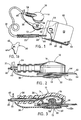
- Figure 1 is a perspective view of the invention just before being attached to connector.
- Figure 1a shows a modified form of electrode.
- Figure 2 is a side elevational view of the connector assembly of Figure 1 on a larger scale after a connection with the electrode has been made.
- Figure 3 is a vertical sectional view of Figure 2.
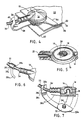
- Figure 4 is a perspective view of the connector assembly in place on an electrode.
- Figure 5 is a bottom view of the female portion of the connector partly in section.
- Figure 6 is a partial perspective view of a modified form connector.
- Figure 7 is a partial perspective view of yet another form of connector.
- Shown in the figures is a
female snap connector 10 to be used in conjunction with a tetheredmale snap connector 12. Thefemale snap connector 10 includes an electricallynonconductive casing 14, e.g. a plastic sheath, within which is ametal connector body 16 having a recess orfemale receptacle 18 that opens downwardly as seen in the figures. Connected to thebody 16 is aconductor 20 having aninsulated covering 21. At the other end ofconductor 20 is aplug 23 with aplug pin 25 which during use is inserted into monitoring or stimulation equipment (not shown). -
Casing 14 includes anextension 24 that surrounds theinsulated conductor 20 where it enters thefemale snap connector 10. Theconnector body 16 is typically hollow and is formed from cup-shaped sheet metal components, the upper one of which is press-fitted at 26 around alower component 19 that contains thefemale receptacle 18 at its center. To hold themale snap connector 12 in place, thereceptacle 18 can be provided with a spring such as ahairpin spring 28 for that purpose. - The
snap connector 12 includes anupper stud portion 34 and alower eyelet portion 30. Theeyelet portion 30 includes acentral pin 36 which projects axially through the center of thestud 34 for holding theconnector 12 together by friction. It will be seen that thestud 34 includes ahorizontal stud plate 32 with an extension ortongue 32a which serves as a lifting device for removing themale snap connector 12 from thefemale snap connector 10 by finger pressure. - A
flexible tether 38 is connected to the male snap connector 11.Flexible tether 38 can be formed from a suitable flexible material such as leather, plastic, rubber and the like, plastic sheet material being preferred. Thus, thetether 38 is mounted by placing its right end over thepin 36. Thestud 34 andstud plate 32 are then forced downwardly over the pin, securely locking the right end of thetether 38 in place between thestud plate 32 and thepin plate 30. At the left end of thetether 38 is an opening 40 through which theinsulated conductor 20, i.e. lead wire, extends. In this way, the tethered snap connector 11 is removably mounted on the lead wire and is preferably slidable thereon. Thetether 38 can be easily mounted on an existingfemale snap connector 10 and itslead wire 20, or removed and replaced whenever required. Usually, once thetether 38 is mounted on a lead wire it is kept there indefinitely, but when not needed for use with a tab electrode, it can be slid back on the wire where it will be out of the way. - Also shown in the figures is a flexible
biomedical electrode 50 which includes a flexible backing composed of two flexible sheets including an upper electrically insulatingsheet 52, e.g. a thin sheet of vinyl plastic, and an electricallyconductive layer 54, e.g. a layer of tin or aluminum foil. To the lower surface ofconductive layer 54 is laminated a flexible layer of an electricallyconductive gel matrix 56 which during use makes electrical contact with the skin of the patient. Thematrix 56, which is usually sticky, is covered prior to use with aremovable cover sheet 60. Extending to the left, as seen in the figures, is atab 62 composed of thelayers electrode 50 anoptional reinforcing tape 64 which in large part covers thetab 62. The reinforcing tape can be used to help support and strengthen thetab 62 and to make possible a more secure connection with thesnap connector gel matrix 56 does not cover the lower surface oftab 62. A punched opening 66 is provided in the center of thetab 62 and tape 64 when present. In this case, thestud 34 of themale snap connector 12 is simply placed through opening 66 prior to being snapped into thefemale receptacle 18 of thefemale snap connector 10. However, as shown in Figure 3, in the event that thetab 62 does not have a punched opening 66 thestud 34, upon being pressed upwardly into thefemale receptacle 18, will puncture the tab as shown in the figure, thereby forming a secure snap connection. - As shown in Figure 1a, an opening 66 in the
tab 62 can comprise two cuts to provide an X configuration. The opening 66a extends all the way through thetab 62 from its top surface to its bottom surface. - Refer now to Figure 6 which illustrates a modified form of tether wherein the same numerals refer to corresponding parts already described. Shown in Figure 6 is a
flexible tether 38a formed from plastic which in this case rather than being a flat sheet is circular in cross-section. Thetether 38a has an enlarged head orcollar 39 within which is provided an opening 39a communicating with aslot 39b. To mount thecollar 39 over thelead wire 20, theslot 39b is spread temporarily, allowing thecollar 39 to be forced onto the insulated lead wire, whereupon the collar will spring back into position as shown in the figure to hold thetether 38a in place. - Refer now to Figure 7. In this case the
tether 38b comprises a flat sheet of flexible plastic material which can have a degree of stiffness. For example, 30 mil polyethylene plastic sheet can be used. At the left end of thetether 38b is an opening 38c adapted to form a sliding fit over theinsulation 21 of thelead wire 20. The opening 38c of thetether 38b has connected to it aslot 38d which is widened at itsouter end 38e to make it easier to force the lead wire into the opening 38c. The tether in both Figures, 6 and 7 can be removed by forcefully pulling it off or, if desired, by sliding it the entire length of the lead wire. - The invention is convenient to use and enables a conventional female snap connector to be connected to both snap-type and snapless tab electrodes. It provides a more secure connection than an alligator clip to a tab type electrode and enables the less expensive tab type electrodes to be used in a variety of circumstances where heretofore only the snap type electrodes could be used. Moreover, the present invention allows greater flexibility in the sense that either snap type or tab electrodes can be used with the same kind of lead wire. The invention is simple in design, rugged in construction and more reliable in operation. Unlike an alligator clip, a snap connector when secured to a tab electrode of the type described cannot be removed by tugging on the lead wire.
Claims (14)
Applications Claiming Priority (4)
| Application Number | Priority Date | Filing Date | Title |
|---|---|---|---|
| US07/325,927 US4911657A (en) | 1989-03-20 | 1989-03-20 | Tethered biomedical electrode connector |
| US325927 | 1989-03-20 | ||
| US445439 | 1989-12-04 | ||
| US07/445,439 US4974594A (en) | 1989-03-20 | 1989-12-04 | Biomedical electrode and removable electrical connector |
Publications (2)
| Publication Number | Publication Date |
|---|---|
| EP0390400A1 true EP0390400A1 (en) | 1990-10-03 |
| EP0390400B1 EP0390400B1 (en) | 1994-06-08 |
Family
ID=26985173
Family Applications (1)
| Application Number | Title | Priority Date | Filing Date |
|---|---|---|---|
| EP90302970A Expired - Lifetime EP0390400B1 (en) | 1989-03-20 | 1990-03-20 | Biomedical electrode and connector |
Country Status (6)
| Country | Link |
|---|---|
| US (1) | US4974594A (en) |
| EP (1) | EP0390400B1 (en) |
| AT (1) | ATE106698T1 (en) |
| DE (1) | DE69009564T2 (en) |
| DK (1) | DK0390400T3 (en) |
| ES (1) | ES2054240T3 (en) |
Cited By (9)
| Publication number | Priority date | Publication date | Assignee | Title |
|---|---|---|---|---|
| EP0484107A1 (en) * | 1990-10-30 | 1992-05-06 | Corometrics Medical Systems, Inc. | Electrical connection device for use in monitoring fetal heart rate |
| WO1994027491A2 (en) * | 1993-06-02 | 1994-12-08 | Minnesota Mining And Manufacturing Company | Intraoral-procedures electrode |
| US5496363A (en) * | 1993-06-02 | 1996-03-05 | Minnesota Mining And Manufacturing Company | Electrode and assembly |
| EP0737438A3 (en) * | 1995-04-12 | 1999-03-10 | R.S. Supplies, Inc. | Medical electrode |
| GB2509341A (en) * | 2012-12-31 | 2014-07-02 | Suunto Oy | Snap for connecting electrodes on a heart rate monitoring garment |
| WO2015036288A1 (en) | 2013-09-16 | 2015-03-19 | Koninklijke Philips N.V. | A bio-medical electrode |
| US9861291B2 (en) | 2012-12-31 | 2018-01-09 | Suunto Oy | Electrode assembly |
| US11058338B2 (en) | 2012-12-31 | 2021-07-13 | Suunto Oy | Electrode assembly |
| US11944441B2 (en) | 2012-12-31 | 2024-04-02 | Suunto Oy | Electro-mechanic assembly and integrated snap connectors |
Families Citing this family (20)
| Publication number | Priority date | Publication date | Assignee | Title |
|---|---|---|---|---|
| US5372125A (en) * | 1993-08-13 | 1994-12-13 | Ludlow Corporation | Positive locking biomedical electrode and connector system |
| US5402780A (en) * | 1993-09-02 | 1995-04-04 | Faasse, Jr.; Adrian L. | Medical electrode with offset contact stud |
| US6223088B1 (en) * | 1998-11-09 | 2001-04-24 | Katecho, Incorporated | Electrode and connector assembly and method for using same |
| US6974935B2 (en) * | 1998-12-04 | 2005-12-13 | Inditherm Plc | Electrical connection |
| US7085598B2 (en) * | 2002-08-23 | 2006-08-01 | Nihon Kohden Corporation | Biological electrode and connector for the same |
| US7085120B2 (en) * | 2003-04-03 | 2006-08-01 | Credence Technologies, Inc. | Self-disengaging wearable grounding device |
| WO2007084552A2 (en) * | 2006-01-17 | 2007-07-26 | Lifesync Corporation | Multi-lead keyhold connector |
| US20090062733A1 (en) * | 2007-08-31 | 2009-03-05 | Kimberly-Clark Worldwide, Inc. | Nasal Insert Device |
| CA2646037C (en) | 2007-12-11 | 2017-11-28 | Tyco Healthcare Group Lp | Ecg electrode connector |
| KR101028584B1 (en) * | 2008-08-27 | 2011-04-12 | 주식회사 바이오프로테크 | Tab electrode and wire leading to the same |
| USD737979S1 (en) * | 2008-12-09 | 2015-09-01 | Covidien Lp | ECG electrode connector |
| CN103687537B (en) | 2011-07-22 | 2016-02-24 | 柯惠有限合伙公司 | Ecg electrode connector |
| FI124657B (en) * | 2012-12-31 | 2014-11-28 | Suunto Oy | Male connector for a telemetric receiver |
| USD771818S1 (en) * | 2013-03-15 | 2016-11-15 | Covidien Lp | ECG electrode connector |
| US9408546B2 (en) | 2013-03-15 | 2016-08-09 | Covidien Lp | Radiolucent ECG electrode system |
| EP2967396B1 (en) | 2013-03-15 | 2019-02-13 | Kpr U.S., Llc | Electrode connector with a conductive member |
| USD807512S1 (en) * | 2014-11-21 | 2018-01-09 | Emfit Oy | Sleep monitor |
| JP6619291B2 (en) * | 2016-05-19 | 2019-12-11 | 日本航空電子工業株式会社 | connector |
| USD873415S1 (en) * | 2018-04-13 | 2020-01-21 | Ningbo Xinwell Medical Technology Co., Ltd | Electrocardiograph cable |
| US20220349869A1 (en) * | 2019-01-25 | 2022-11-03 | Axion Biosystems, Inc. | Devices and systems with integrated electrodes or optical elements for monitoring cell cultures and related methods |
Citations (5)
| Publication number | Priority date | Publication date | Assignee | Title |
|---|---|---|---|---|
| US2314751A (en) * | 1940-11-23 | 1943-03-23 | United Carr Fastener Corp | Electrical connection |
| US3556105A (en) * | 1968-05-24 | 1971-01-19 | Lillian B Shepard | Electrical stimulator and mitten |
| US3928079A (en) * | 1974-10-07 | 1975-12-23 | Gen Motors Corp | Battery cable with detachably retained connector |
| EP0195451A2 (en) * | 1985-03-20 | 1986-09-24 | ARBO Medizin-Technologie GmbH | Electrode for measuring physiological signals |
| US4776350A (en) * | 1986-01-07 | 1988-10-11 | Physio-Control Corporation | External electrode for heart stimulation and connector therefor |
Family Cites Families (22)
| Publication number | Priority date | Publication date | Assignee | Title |
|---|---|---|---|---|
| CA675494A (en) * | 1963-12-03 | Theratron Corporation | Electrode for electronic therapeutic and diagnostic equipment | |
| US2943627A (en) * | 1957-04-05 | 1960-07-05 | William L Howell | Electrode |
| US3720209A (en) * | 1968-03-11 | 1973-03-13 | Medical Plastics Inc | Plate electrode |
| US3911906A (en) * | 1974-04-24 | 1975-10-14 | Survival Technology | Dry applied and operably dry electrode device |
| US4126126A (en) * | 1976-07-27 | 1978-11-21 | C. R. Bard, Inc. | Non-metallic pregelled electrode |
| US4112941A (en) * | 1977-01-06 | 1978-09-12 | Minnesota Mining And Manufacturing Company | Electrode and magnetic connector assembly |
| US4072388A (en) * | 1977-04-06 | 1978-02-07 | Marquette Electronics, Inc. | Anti-snag device for electrode lead clips |
| US4273135A (en) * | 1977-08-19 | 1981-06-16 | Minnesota Mining And Manufacturing Company | Biomedical electrode |
| US4166465A (en) * | 1977-10-17 | 1979-09-04 | Neomed Incorporated | Electrosurgical dispersive electrode |
| US4239046A (en) * | 1978-09-21 | 1980-12-16 | Ong Lincoln T | Medical electrode |
| US4522211A (en) * | 1979-12-06 | 1985-06-11 | C. R. Bard, Inc. | Medical electrode construction |
| US4702256A (en) * | 1984-10-24 | 1987-10-27 | Andover Medical Incorporated | Electrical connector for a disposable electrode |
| US4685467A (en) * | 1985-07-10 | 1987-08-11 | American Hospital Supply Corporation | X-ray transparent medical electrodes and lead wires and assemblies thereof |
| US4671591A (en) * | 1985-07-15 | 1987-06-09 | Physio-Control Corporation | Electrical connector |
| US4635642A (en) * | 1985-07-18 | 1987-01-13 | American Hospital Supply Corporation | Medical electrode with reusable conductor |
| US4674512A (en) * | 1986-02-03 | 1987-06-23 | Lectec Corporation | Medical electrode for monitoring and diagnostic use |
| LU86308A1 (en) * | 1986-02-14 | 1987-09-10 | Oreal | TINCTORIAL COMPOSITION FOR KERATINIC FIBERS BASED ON 2-NITROMETAPHENYLENEDIAMINES, PROCESS FOR PREPARING THESE COMPOUNDS AND NOVEL 2-NITRO-METAPHENYLENEDIAMINES USED |
| US4731032A (en) * | 1986-04-09 | 1988-03-15 | Thomas & Betts Corporation | Protective cover for electrical connector |
| US4706680A (en) * | 1986-06-30 | 1987-11-17 | Nepera Inc. | Conductive adhesive medical electrode assemblies |
| US4798208A (en) * | 1987-12-09 | 1989-01-17 | Faasse Jr Adrian L | Diagnostic electrode |
| JPH02159639A (en) * | 1988-12-14 | 1990-06-19 | Mitsubishi Electric Corp | Simulation collating circuit for logic circuit |
| US4911657A (en) * | 1989-03-20 | 1990-03-27 | Lec Tec Corporation | Tethered biomedical electrode connector |
-
1989
- 1989-12-04 US US07/445,439 patent/US4974594A/en not_active Expired - Fee Related
-
1990
- 1990-03-20 DE DE69009564T patent/DE69009564T2/en not_active Expired - Fee Related
- 1990-03-20 EP EP90302970A patent/EP0390400B1/en not_active Expired - Lifetime
- 1990-03-20 DK DK90302970.0T patent/DK0390400T3/en active
- 1990-03-20 ES ES90302970T patent/ES2054240T3/en not_active Expired - Lifetime
- 1990-03-20 AT AT90302970T patent/ATE106698T1/en not_active IP Right Cessation
Patent Citations (5)
| Publication number | Priority date | Publication date | Assignee | Title |
|---|---|---|---|---|
| US2314751A (en) * | 1940-11-23 | 1943-03-23 | United Carr Fastener Corp | Electrical connection |
| US3556105A (en) * | 1968-05-24 | 1971-01-19 | Lillian B Shepard | Electrical stimulator and mitten |
| US3928079A (en) * | 1974-10-07 | 1975-12-23 | Gen Motors Corp | Battery cable with detachably retained connector |
| EP0195451A2 (en) * | 1985-03-20 | 1986-09-24 | ARBO Medizin-Technologie GmbH | Electrode for measuring physiological signals |
| US4776350A (en) * | 1986-01-07 | 1988-10-11 | Physio-Control Corporation | External electrode for heart stimulation and connector therefor |
Cited By (14)
| Publication number | Priority date | Publication date | Assignee | Title |
|---|---|---|---|---|
| EP0484107A1 (en) * | 1990-10-30 | 1992-05-06 | Corometrics Medical Systems, Inc. | Electrical connection device for use in monitoring fetal heart rate |
| WO1994027491A2 (en) * | 1993-06-02 | 1994-12-08 | Minnesota Mining And Manufacturing Company | Intraoral-procedures electrode |
| WO1994027491A3 (en) * | 1993-06-02 | 1995-02-02 | Minnesota Mining & Mfg | Intraoral-procedures electrode |
| US5496363A (en) * | 1993-06-02 | 1996-03-05 | Minnesota Mining And Manufacturing Company | Electrode and assembly |
| EP0737438A3 (en) * | 1995-04-12 | 1999-03-10 | R.S. Supplies, Inc. | Medical electrode |
| US11058338B2 (en) | 2012-12-31 | 2021-07-13 | Suunto Oy | Electrode assembly |
| GB2509341A (en) * | 2012-12-31 | 2014-07-02 | Suunto Oy | Snap for connecting electrodes on a heart rate monitoring garment |
| GB2509341B (en) * | 2012-12-31 | 2015-11-18 | Suunto Oy | Snap for integration with a garment |
| US9597005B2 (en) | 2012-12-31 | 2017-03-21 | Suunto Oy | Snap for integration with a garment |
| US11944441B2 (en) | 2012-12-31 | 2024-04-02 | Suunto Oy | Electro-mechanic assembly and integrated snap connectors |
| CN103908047B (en) * | 2012-12-31 | 2017-05-03 | 松拓有限公司 | Snap for integration with a garment |
| US9861291B2 (en) | 2012-12-31 | 2018-01-09 | Suunto Oy | Electrode assembly |
| WO2015036288A1 (en) | 2013-09-16 | 2015-03-19 | Koninklijke Philips N.V. | A bio-medical electrode |
| US9603541B2 (en) | 2013-09-16 | 2017-03-28 | Koninklijke Philips N.V. | Bio-medical electrode |
Also Published As
| Publication number | Publication date |
|---|---|
| DK0390400T3 (en) | 1994-07-04 |
| DE69009564T2 (en) | 1994-09-22 |
| DE69009564D1 (en) | 1994-07-14 |
| EP0390400B1 (en) | 1994-06-08 |
| ATE106698T1 (en) | 1994-06-15 |
| US4974594A (en) | 1990-12-04 |
| ES2054240T3 (en) | 1994-08-01 |
Similar Documents
| Publication | Publication Date | Title |
|---|---|---|
| EP0390400B1 (en) | Biomedical electrode and connector | |
| US4911657A (en) | Tethered biomedical electrode connector | |
| AU636019B2 (en) | Low profile electrode connector | |
| US4715382A (en) | Flat biomedical electrode with reuseable lead wire | |
| AU725038B2 (en) | Method and assembly of member and terminal | |
| US4852571A (en) | Disposable biopotential electrode | |
| US4797125A (en) | Electrode connector for substrate electrodes | |
| EP1066082B1 (en) | Implantable medical electrode contacts | |
| EP1929942B1 (en) | Electrode connector | |
| US4442840A (en) | Electrical connector apparatus and method for a temporary cardiac pacing wire | |
| US4832608A (en) | Electrode belt adapter | |
| US4209020A (en) | Electrode assembly | |
| EP2777495A1 (en) | Reduce motion artifact electrode | |
| CA1175512A (en) | Electrical terminal | |
| JP2001506154A (en) | Biomedical electrodes with disposable electrodes and reusable lead adapters that interface with standard lead connectors | |
| CA2057175A1 (en) | Medical electrode assembly | |
| US5566672A (en) | Biomedical electrode | |
| US5168875A (en) | Elongated strip electrode arrangement and method | |
| US5197472A (en) | Disposable leg plate electrode assembly | |
| US5176676A (en) | Plug connector for a surface electrode | |
| US4576426A (en) | Flexible printed circuit connector and contact eyelet therefor | |
| JPH058967Y2 (en) | ||
| EP0836864A2 (en) | Defibrillator electrode | |
| JPH0534641Y2 (en) | ||
| JPH062645Y2 (en) | Multi-electrode type living body induction electrode |
Legal Events
| Date | Code | Title | Description |
|---|---|---|---|
| PUAI | Public reference made under article 153(3) epc to a published international application that has entered the european phase |
Free format text: ORIGINAL CODE: 0009012 |
|
| AK | Designated contracting states |
Kind code of ref document: A1 Designated state(s): AT BE CH DE DK ES FR GB IT LI NL SE |
|
| 17P | Request for examination filed |
Effective date: 19901207 |
|
| 17Q | First examination report despatched |
Effective date: 19930309 |
|
| GRAA | (expected) grant |
Free format text: ORIGINAL CODE: 0009210 |
|
| ITF | It: translation for a ep patent filed |
Owner name: STUDIO AVV. LIA STELLA |
|
| AK | Designated contracting states |
Kind code of ref document: B1 Designated state(s): AT BE CH DE DK ES FR GB IT LI NL SE |
|
| PG25 | Lapsed in a contracting state [announced via postgrant information from national office to epo] |
Ref country code: NL Effective date: 19940608 Ref country code: LI Effective date: 19940608 Ref country code: CH Effective date: 19940608 Ref country code: AT Effective date: 19940608 |
|
| REF | Corresponds to: |
Ref document number: 106698 Country of ref document: AT Date of ref document: 19940615 Kind code of ref document: T |
|
| REG | Reference to a national code |
Ref country code: DK Ref legal event code: T3 |
|
| REF | Corresponds to: |
Ref document number: 69009564 Country of ref document: DE Date of ref document: 19940714 |
|
| REG | Reference to a national code |
Ref country code: ES Ref legal event code: FG2A Ref document number: 2054240 Country of ref document: ES Kind code of ref document: T3 |
|
| ET | Fr: translation filed | ||
| REG | Reference to a national code |
Ref country code: CH Ref legal event code: PL |
|
| NLV1 | Nl: lapsed or annulled due to failure to fulfill the requirements of art. 29p and 29m of the patents act | ||
| EAL | Se: european patent in force in sweden |
Ref document number: 90302970.0 |
|
| PLBE | No opposition filed within time limit |
Free format text: ORIGINAL CODE: 0009261 |
|
| STAA | Information on the status of an ep patent application or granted ep patent |
Free format text: STATUS: NO OPPOSITION FILED WITHIN TIME LIMIT |
|
| 26N | No opposition filed | ||
| PGFP | Annual fee paid to national office [announced via postgrant information from national office to epo] |
Ref country code: GB Payment date: 19960311 Year of fee payment: 7 |
|
| PGFP | Annual fee paid to national office [announced via postgrant information from national office to epo] |
Ref country code: BE Payment date: 19960312 Year of fee payment: 7 |
|
| PGFP | Annual fee paid to national office [announced via postgrant information from national office to epo] |
Ref country code: ES Payment date: 19960315 Year of fee payment: 7 |
|
| PGFP | Annual fee paid to national office [announced via postgrant information from national office to epo] |
Ref country code: SE Payment date: 19960318 Year of fee payment: 7 |
|
| PGFP | Annual fee paid to national office [announced via postgrant information from national office to epo] |
Ref country code: DE Payment date: 19960323 Year of fee payment: 7 |
|
| PGFP | Annual fee paid to national office [announced via postgrant information from national office to epo] |
Ref country code: FR Payment date: 19960329 Year of fee payment: 7 |
|
| PGFP | Annual fee paid to national office [announced via postgrant information from national office to epo] |
Ref country code: DK Payment date: 19960401 Year of fee payment: 7 |
|
| PG25 | Lapsed in a contracting state [announced via postgrant information from national office to epo] |
Ref country code: GB Effective date: 19970320 Ref country code: DK Effective date: 19970320 |
|
| REG | Reference to a national code |
Ref country code: DK Ref legal event code: EBP |
|
| PG25 | Lapsed in a contracting state [announced via postgrant information from national office to epo] |
Ref country code: SE Effective date: 19970321 Ref country code: ES Free format text: LAPSE BECAUSE OF NON-PAYMENT OF DUE FEES Effective date: 19970321 |
|
| PG25 | Lapsed in a contracting state [announced via postgrant information from national office to epo] |
Ref country code: BE Effective date: 19970331 |
|
| BERE | Be: lapsed |
Owner name: LECTEC CORP. Effective date: 19970331 |
|
| GBPC | Gb: european patent ceased through non-payment of renewal fee |
Effective date: 19970320 |
|
| PG25 | Lapsed in a contracting state [announced via postgrant information from national office to epo] |
Ref country code: FR Free format text: LAPSE BECAUSE OF NON-PAYMENT OF DUE FEES Effective date: 19971128 |
|
| PG25 | Lapsed in a contracting state [announced via postgrant information from national office to epo] |
Ref country code: DE Effective date: 19971202 |
|
| EUG | Se: european patent has lapsed |
Ref document number: 90302970.0 |
|
| REG | Reference to a national code |
Ref country code: FR Ref legal event code: ST |
|
| REG | Reference to a national code |
Ref country code: ES Ref legal event code: FD2A Effective date: 19990503 |
|
| PG25 | Lapsed in a contracting state [announced via postgrant information from national office to epo] |
Ref country code: IT Free format text: LAPSE BECAUSE OF NON-PAYMENT OF DUE FEES Effective date: 20050320 |