EP0398658B1 - Catalytic heat generator - Google Patents
Catalytic heat generator Download PDFInfo
- Publication number
- EP0398658B1 EP0398658B1 EP90305239A EP90305239A EP0398658B1 EP 0398658 B1 EP0398658 B1 EP 0398658B1 EP 90305239 A EP90305239 A EP 90305239A EP 90305239 A EP90305239 A EP 90305239A EP 0398658 B1 EP0398658 B1 EP 0398658B1
- Authority
- EP
- European Patent Office
- Prior art keywords
- coating layer
- catalyst coating
- heat generator
- heat
- weight
- Prior art date
- Legal status (The legal status is an assumption and is not a legal conclusion. Google has not performed a legal analysis and makes no representation as to the accuracy of the status listed.)
- Expired - Lifetime
Links
- 230000003197 catalytic effect Effects 0.000 title description 6
- 239000003054 catalyst Substances 0.000 claims description 83
- 239000011247 coating layer Substances 0.000 claims description 81
- VYPSYNLAJGMNEJ-UHFFFAOYSA-N silicon dioxide Inorganic materials O=[Si]=O VYPSYNLAJGMNEJ-UHFFFAOYSA-N 0.000 claims description 80
- QVQLCTNNEUAWMS-UHFFFAOYSA-N barium oxide Chemical compound [Ba]=O QVQLCTNNEUAWMS-UHFFFAOYSA-N 0.000 claims description 46
- 239000010453 quartz Substances 0.000 claims description 34
- 239000002002 slurry Substances 0.000 claims description 27
- 239000000377 silicon dioxide Substances 0.000 claims description 21
- AYJRCSIUFZENHW-UHFFFAOYSA-L barium carbonate Chemical compound [Ba+2].[O-]C([O-])=O AYJRCSIUFZENHW-UHFFFAOYSA-L 0.000 claims description 16
- GWEVSGVZZGPLCZ-UHFFFAOYSA-N Titan oxide Chemical compound O=[Ti]=O GWEVSGVZZGPLCZ-UHFFFAOYSA-N 0.000 claims description 15
- 229910000420 cerium oxide Inorganic materials 0.000 claims description 15
- BMMGVYCKOGBVEV-UHFFFAOYSA-N oxo(oxoceriooxy)cerium Chemical compound [Ce]=O.O=[Ce]=O BMMGVYCKOGBVEV-UHFFFAOYSA-N 0.000 claims description 15
- OGIDPMRJRNCKJF-UHFFFAOYSA-N titanium oxide Inorganic materials [Ti]=O OGIDPMRJRNCKJF-UHFFFAOYSA-N 0.000 claims description 15
- PNEYBMLMFCGWSK-UHFFFAOYSA-N aluminium oxide Inorganic materials [O-2].[O-2].[O-2].[Al+3].[Al+3] PNEYBMLMFCGWSK-UHFFFAOYSA-N 0.000 claims description 14
- 229910052751 metal Inorganic materials 0.000 claims description 10
- 239000002184 metal Substances 0.000 claims description 10
- 239000002245 particle Substances 0.000 claims description 10
- BASFCYQUMIYNBI-UHFFFAOYSA-N platinum Chemical group [Pt] BASFCYQUMIYNBI-UHFFFAOYSA-N 0.000 claims description 9
- 239000008119 colloidal silica Substances 0.000 claims description 6
- 238000010304 firing Methods 0.000 claims description 5
- 239000010410 layer Substances 0.000 claims description 5
- 150000003839 salts Chemical class 0.000 claims description 5
- 239000011248 coating agent Substances 0.000 claims description 4
- 238000000576 coating method Methods 0.000 claims description 4
- 230000002093 peripheral effect Effects 0.000 claims description 4
- 238000001035 drying Methods 0.000 claims description 3
- WNROFYMDJYEPJX-UHFFFAOYSA-K aluminium hydroxide Chemical compound [OH-].[OH-].[OH-].[Al+3] WNROFYMDJYEPJX-UHFFFAOYSA-K 0.000 claims 2
- 229910021502 aluminium hydroxide Inorganic materials 0.000 claims 2
- 235000012239 silicon dioxide Nutrition 0.000 description 32
- UGFAIRIUMAVXCW-UHFFFAOYSA-N Carbon monoxide Chemical compound [O+]#[C-] UGFAIRIUMAVXCW-UHFFFAOYSA-N 0.000 description 15
- 229910002091 carbon monoxide Inorganic materials 0.000 description 15
- QGZKDVFQNNGYKY-UHFFFAOYSA-N Ammonia Chemical compound N QGZKDVFQNNGYKY-UHFFFAOYSA-N 0.000 description 14
- 238000000746 purification Methods 0.000 description 12
- 230000035939 shock Effects 0.000 description 12
- 230000000694 effects Effects 0.000 description 9
- 238000010438 heat treatment Methods 0.000 description 9
- 229910001120 nichrome Inorganic materials 0.000 description 8
- 230000005855 radiation Effects 0.000 description 7
- 229910021529 ammonia Inorganic materials 0.000 description 6
- 230000035943 smell Effects 0.000 description 6
- RQPZNWPYLFFXCP-UHFFFAOYSA-L barium dihydroxide Chemical compound [OH-].[OH-].[Ba+2] RQPZNWPYLFFXCP-UHFFFAOYSA-L 0.000 description 5
- 229910001863 barium hydroxide Inorganic materials 0.000 description 5
- -1 etc. Substances 0.000 description 5
- 230000001473 noxious effect Effects 0.000 description 5
- XLYOFNOQVPJJNP-UHFFFAOYSA-N water Substances O XLYOFNOQVPJJNP-UHFFFAOYSA-N 0.000 description 5
- 230000004913 activation Effects 0.000 description 4
- 239000007789 gas Substances 0.000 description 4
- 239000000463 material Substances 0.000 description 4
- KDLHZDBZIXYQEI-UHFFFAOYSA-N palladium Substances [Pd] KDLHZDBZIXYQEI-UHFFFAOYSA-N 0.000 description 4
- 239000000843 powder Substances 0.000 description 4
- XNDZQQSKSQTQQD-UHFFFAOYSA-N 3-methylcyclohex-2-en-1-ol Chemical compound CC1=CC(O)CCC1 XNDZQQSKSQTQQD-UHFFFAOYSA-N 0.000 description 3
- 239000002253 acid Substances 0.000 description 3
- 239000000919 ceramic Substances 0.000 description 3
- 235000019504 cigarettes Nutrition 0.000 description 3
- 238000000034 method Methods 0.000 description 3
- PIBWKRNGBLPSSY-UHFFFAOYSA-L palladium(II) chloride Chemical compound Cl[Pd]Cl PIBWKRNGBLPSSY-UHFFFAOYSA-L 0.000 description 3
- 239000000779 smoke Substances 0.000 description 3
- 238000005507 spraying Methods 0.000 description 3
- XKRFYHLGVUSROY-UHFFFAOYSA-N Argon Chemical compound [Ar] XKRFYHLGVUSROY-UHFFFAOYSA-N 0.000 description 2
- UQSXHKLRYXJYBZ-UHFFFAOYSA-N Iron oxide Chemical compound [Fe]=O UQSXHKLRYXJYBZ-UHFFFAOYSA-N 0.000 description 2
- 230000010718 Oxidation Activity Effects 0.000 description 2
- 239000011230 binding agent Substances 0.000 description 2
- HSJPMRKMPBAUAU-UHFFFAOYSA-N cerium(3+);trinitrate Chemical compound [Ce+3].[O-][N+]([O-])=O.[O-][N+]([O-])=O.[O-][N+]([O-])=O HSJPMRKMPBAUAU-UHFFFAOYSA-N 0.000 description 2
- 238000007598 dipping method Methods 0.000 description 2
- 239000011521 glass Substances 0.000 description 2
- 239000012212 insulator Substances 0.000 description 2
- 229910000953 kanthal Inorganic materials 0.000 description 2
- 239000007787 solid Substances 0.000 description 2
- 229910052684 Cerium Inorganic materials 0.000 description 1
- 229910002651 NO3 Inorganic materials 0.000 description 1
- NHNBFGGVMKEFGY-UHFFFAOYSA-N Nitrate Chemical compound [O-][N+]([O-])=O NHNBFGGVMKEFGY-UHFFFAOYSA-N 0.000 description 1
- 230000000996 additive effect Effects 0.000 description 1
- 229910052786 argon Inorganic materials 0.000 description 1
- 229910052788 barium Inorganic materials 0.000 description 1
- DSAJWYNOEDNPEQ-UHFFFAOYSA-N barium atom Chemical compound [Ba] DSAJWYNOEDNPEQ-UHFFFAOYSA-N 0.000 description 1
- 230000015572 biosynthetic process Effects 0.000 description 1
- 238000007664 blowing Methods 0.000 description 1
- 238000006555 catalytic reaction Methods 0.000 description 1
- ZMIGMASIKSOYAM-UHFFFAOYSA-N cerium Chemical compound [Ce][Ce][Ce][Ce][Ce][Ce][Ce][Ce][Ce][Ce][Ce][Ce][Ce][Ce][Ce][Ce][Ce][Ce][Ce][Ce][Ce][Ce][Ce][Ce][Ce][Ce][Ce][Ce][Ce][Ce][Ce][Ce][Ce][Ce][Ce][Ce][Ce][Ce] ZMIGMASIKSOYAM-UHFFFAOYSA-N 0.000 description 1
- QQZMWMKOWKGPQY-UHFFFAOYSA-N cerium(3+);trinitrate;hexahydrate Chemical compound O.O.O.O.O.O.[Ce+3].[O-][N+]([O-])=O.[O-][N+]([O-])=O.[O-][N+]([O-])=O QQZMWMKOWKGPQY-UHFFFAOYSA-N 0.000 description 1
- 238000006243 chemical reaction Methods 0.000 description 1
- 239000004927 clay Substances 0.000 description 1
- 150000001875 compounds Chemical class 0.000 description 1
- 229910052878 cordierite Inorganic materials 0.000 description 1
- JSKIRARMQDRGJZ-UHFFFAOYSA-N dimagnesium dioxido-bis[(1-oxido-3-oxo-2,4,6,8,9-pentaoxa-1,3-disila-5,7-dialuminabicyclo[3.3.1]nonan-7-yl)oxy]silane Chemical compound [Mg++].[Mg++].[O-][Si]([O-])(O[Al]1O[Al]2O[Si](=O)O[Si]([O-])(O1)O2)O[Al]1O[Al]2O[Si](=O)O[Si]([O-])(O1)O2 JSKIRARMQDRGJZ-UHFFFAOYSA-N 0.000 description 1
- 238000003618 dip coating Methods 0.000 description 1
- 238000009503 electrostatic coating Methods 0.000 description 1
- 150000002430 hydrocarbons Chemical class 0.000 description 1
- XLYOFNOQVPJJNP-UHFFFAOYSA-M hydroxide Chemical compound [OH-] XLYOFNOQVPJJNP-UHFFFAOYSA-M 0.000 description 1
- 239000011261 inert gas Substances 0.000 description 1
- 238000003801 milling Methods 0.000 description 1
- 229910000480 nickel oxide Inorganic materials 0.000 description 1
- 229910017464 nitrogen compound Inorganic materials 0.000 description 1
- 150000002830 nitrogen compounds Chemical class 0.000 description 1
- 229910000069 nitrogen hydride Inorganic materials 0.000 description 1
- 210000001331 nose Anatomy 0.000 description 1
- GNRSAWUEBMWBQH-UHFFFAOYSA-N oxonickel Chemical compound [Ni]=O GNRSAWUEBMWBQH-UHFFFAOYSA-N 0.000 description 1
- 238000002360 preparation method Methods 0.000 description 1
- 238000007650 screen-printing Methods 0.000 description 1
- RMAQACBXLXPBSY-UHFFFAOYSA-N silicic acid Chemical compound O[Si](O)(O)O RMAQACBXLXPBSY-UHFFFAOYSA-N 0.000 description 1
- 230000002269 spontaneous effect Effects 0.000 description 1
- 238000005979 thermal decomposition reaction Methods 0.000 description 1
- WFKWXMTUELFFGS-UHFFFAOYSA-N tungsten Chemical compound [W] WFKWXMTUELFFGS-UHFFFAOYSA-N 0.000 description 1
Images
Classifications
-
- H—ELECTRICITY
- H05—ELECTRIC TECHNIQUES NOT OTHERWISE PROVIDED FOR
- H05B—ELECTRIC HEATING; ELECTRIC LIGHT SOURCES NOT OTHERWISE PROVIDED FOR; CIRCUIT ARRANGEMENTS FOR ELECTRIC LIGHT SOURCES, IN GENERAL
- H05B3/00—Ohmic-resistance heating
- H05B3/10—Heater elements characterised by the composition or nature of the materials or by the arrangement of the conductor
-
- H—ELECTRICITY
- H05—ELECTRIC TECHNIQUES NOT OTHERWISE PROVIDED FOR
- H05B—ELECTRIC HEATING; ELECTRIC LIGHT SOURCES NOT OTHERWISE PROVIDED FOR; CIRCUIT ARRANGEMENTS FOR ELECTRIC LIGHT SOURCES, IN GENERAL
- H05B3/00—Ohmic-resistance heating
- H05B3/40—Heating elements having the shape of rods or tubes
- H05B3/42—Heating elements having the shape of rods or tubes non-flexible
- H05B3/44—Heating elements having the shape of rods or tubes non-flexible heating conductor arranged within rods or tubes of insulating material
Definitions
- This invention relates to a heat generator for use in room heater, water boiler, drier, etc.
- the conventional heat generators are metal wires such as nichrome wire and kanthal wire in a coiled state or encased in tubes such as a metallic tube, a quartz tube and ceramic tube, or further the tubes being coated with cordierite, clay or glass, as disclosed in U.S.-A-3,179,789 and U.S.-A-4426570, or a highly far infrared radiation material such as nickel oxide, iron oxide, etc., and ceramic heaters containing an electric resistor in sintered ceramics, etc.
- heat generator In room heaters, water boilers and driers, materials are heated by the heat generator through heat conduction, convection and radiation, for example, by direct heating from the heat generator, forced air blowing to the heat generator by a fan to generate heated air, or by providing a reflection plate behind the heat generator to conduct radiation heating.
- the conventional heat generator has the following problems.
- the heat generator heats air in the room and also heats cigarette smoke or smells suspended in the room.
- the higher the temperature the more sensitive to human noses the smelling components.
- the smelling components once adsorbed on the structural material or furnitures in the room are again vaporized and suspended in the room atmosphere. Since the conventional heat generator has no capacity to purify the smelling components, smells are often more sensitive when an electric stove is used in the room than when not. Such a phenomenon has been a problem.
- An object of the present invention is to provide a heat generator capable of removing smells or noxious gases with a simple structure, thereby solving the problem of the prior art.
- the present invention as defined in claim 1 provides a heat generator, which obviates or mitigates the aforesaid problem.
- the heat generator tube Since the heat generator tube is provided with the catalyst coating layer on the tube surface, the heat generator can heat both of a material to be heated and the catalyst coating layer. Furthermore, the heat generator tube is surrounded by the catalyst coating layer, the catalyst coating layer can efficiently absorb heat from the electric resistor by radiation and conduction and thus can be heated to the activation temperature of the catalyst within a short time.
- the present catalyst coating layer contains silica and thus strong adhesion of the layer to the quartz tube can be obtained and also the heat conduction from the quartz tube can be carried out very rapidly.
- the heat generator also heats air around the heat generator and thus an air stream as a convention much circulates around the heat generator. When the air stream contacts the catalyst heated to more than the activation temperature by heating of the heat generator, the smelling components and noxious components in the air are oxidized and purified by the catalytic reaction before leaving the heat generator.
- the electric resistor for use in the present heat generator includes a metal wire, such as a nichrome wire or a kanthal wire, in a coiled form, and a tungsten wire, etc. sealed in a quartz tube together with an inert gas such as an argon gas, etc.
- the quartz tube for use in the present invention is a tube of glass containing at least 95% by weight of silica.
- the present catalyst coating layer contains silica. By inclusion of silica in the catalyst coating layer, strong adhesion of the catalyst coating layer to the quartz tube can be obtained.
- the present catalyst coating layer contains 6 to 40% by weight of silica. Above 40% by weight of silica the catalyst coating layer is liable to crack, resulting in a decrease in the adhesion, whereas below 6% by weight of silica a sufficient effect of silica upon the improvement of adhesion cannot be obtained.
- the present catalyst coating layer has a specific surface area of at least 10 m2/g.
- the far infrared radiation ratio i.e. the amount of far infrared rays to be radiated, increases with increasing specific surface area of the catalyst coating layer, and a sufficient far infrared radiation ratio can be obtained with a specific surface area of at least 10 m2/g.
- the present catalyst coating layer contains cerium oxide.
- cerium oxide By inclusion of cerium oxide in the catalyst coating layer, not only the heat resistance of the catalyst coating layer, but also the catalytic oxidation activity to hydrocarbon compounds can be improved. It is desirable that the catalyst coating layer contains 5 to 30% by weight of cerium oxide. Above 30% by weight of cerium oxide, the heat resistance of the catalyst coating layer is lowered, whereas below 5% by weight a sufficient effect of cerium oxide cannot be obtained.
- the present catalyst coating layer contains barium oxide.
- barium oxide By inclusion of barium oxide in the catalyst coating layer, the heat resistance of the catalyst coating layer can be improved. It is desirable that the present catalyst coating layer contains 1 to 10% by weight of barium oxide. Above 10% by weight of barium oxide, the adhesion of the catalyst coating layer is lowered, whereas below 1% by weight of barium oxide, a sufficient effect of barium oxide cannot be obtained.
- the amount of barium carbonate to be contained in the catalyst coating layer is 1 to 10% by weight in terms of barium oxide.
- the catalyst coating layer contains titanium oxide.
- titanium oxide By inclusion of titanium oxide in the catalyst coating layer, the catalytic oxidation activity to nitrogen compounds such as ammonia, etc. can be improved. It is desirable that the catalyst coating layer contains 4 to 30% by weight of titanium oxide. Above 30% by weight of titanium oxide, the adhesion of the catalyst coating layer is lowered, whereas below 4% by weight of titanium oxide, a sufficient effect of titanium oxide cannot be obtained.
- the present catalyst coating layer on the surface of a quartz tube, it is desirable to roughen the surface of a quartz tube and then provide a catalyst coating layer thereon, or to thoroughly defat the surface of a quartz tube and then provide a catalyst coating layer, whereby adhesion can be improved between the quartz tube and the catalyst coating layer.
- the present catalyst coating layer can be formed in various ways, for example, by spray coating, dip coating, electrostatic coating, roll coating, screen printing, etc.
- the particles in a slurry for forming the present catalyst coating layer have main particle sizes of 1 ⁇ m to 9 ⁇ m. Above 9 ⁇ m, the catalyst coating layer turns soft, whereas below 1 ⁇ m the catalyst coating layer is liable to crack.
- silica means silicon dioxide, and silicic acid can be used in place of silica.
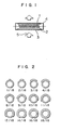
- Fig. 1 is a view showing the structure and action according to one embodiment of the present heat generator.
- Fig. 2 is a views showing various coating coverages of the present catalyst coating layer provided on the surface of a quartz tube.
- a slurry A 1,000 g of active alumina powder, 1,000 g of colloidal alumina containing 10% by weight of alumina, 100 g of aluminum nitrate nonahydrate, 1,000 g of colloidal silica containing 20% by weight of silica, 1,200 g of water, 30 g of chloroplatinic acid in terms of Pt, and 15 g of palladium chloride in terms of Pd were added to a ball mill and thoroughly mixed to prepare a slurry A.
- the thus prepared slurry A was applied to the surface of a quartz tube, 10 mm in outer diameter, 9 mm in inner diameter, 15 cm long, by spray coating, dried at 100°C for 2 hours and then fired at 500°C for one hour to obtain a quartz tube with a catalyst coating layer. From the thus prepared quartz tube, a nichrome wire as an electric resistor and an insulator was prepared a heat generator A of the present invention.
- the amount of the catalyst coating layer was 0.2 g, the amounts of the platinum group metals contained were 5.12 mg of Pt and 2.56 mg of Pd.
- the present heat generator had the structure shown in Fig. 1.
- the present heat generator A comprises a nichrome wire 1 of 300 W, a quartz tube 2 and a catalyst coating layer 3 formed on the surface of the quartz tube 3, the heat generator A being insulated and supported by insulators 4.
- the catalyst coating layer is provided to cover the entire periphery of the quartz tube 2, and thus the catalyst coating layer 3 is irradiated with the heat rays emitted from the nichrome wire 1 in all the radial directions, and the radiation heating of the catalyst coating layer 3 can be efficiently carried out.
- the catalyst is heated to the activation temperature of the catalyst within a short time and the catalyst coating layer can be elevated to a high temperature.
- the heat generator A heats air around the heat generator A, and thus an air stream 5 is caused to circulate as a convention around the heat generator A.
- an air stream 5 contacts the catalyst coating layer heated to the activation temperature by heating of the nichrome wire 1 or is diffused into the catalyst coating layer, smells or noxious components contained in the air around the heat generator A, for example, carbon monoxide (CO) or ammonia (NH3) is purified by the catalytic action.
- CO carbon monoxide
- NH3 ammonia
- Example 1 Slurries were prepared in the same manner as in Example 1, except that the content of colloidal silica was changed between 1% and 60% by weight in terms of silica on the basis of total solid matters of slurry A prepared in Example 1, while correspondingly reducing the alumina content to make up for the silica increment, and heat generators each with 0.2 g of the catalyst coating layers formed on the entire outer surfaces of quartz tubes from the thus prepared individual slurries were prepared in the same manner as in Example 1. The thus prepared heat generators were subjected to a heat shock test to investigate the adhesion of the catalyst coating layers.
- the heat shock test was carried out by passing an electric current through the electric resistor contained in the quartz tube, setting the surface temperature at the center of the heat generator to intervals of 25°C, maintaining the heat generator at each interval for 10 minutes, and then dipping the heat generator into water at room temperature to investigate occurrence of peeling of the catalyst coating layer, and repeating the foregoing procedure until the peeling occurs, where the maximum temperature at which no peeling occurred was defined as a heat shock-resistant temperature.
- Table 1 The results are shown in Table 1.
- heat generators each with the same amount of the catalyst coating layers containing various contents of cerium oxide, as shown in Table 2, as that of the catalyst coating layer of Example 1, formed on the surfaces of quartz tubes, were prepared from the thus prepared slurries in the same manner as in Example 1. Results of heat resistance tests of the heat generators are shown in Table 2.
- the heat resistance test was carried out by firing the heat generator at 800°C in air for 50 hours and then determining CO purification efficiency of the fired heat generators.
- the CO purification efficiency was determined by placing the fired heat generator in a quartz tube, 15 mm in inner diameter, passing air containing 1,000 ppm CO therethrough at a space velocity of 10,000 hr ⁇ on the basis of the volume of the catalyst coating layer, while keeping the catalyst coating layer at 250°C, and measuring CO concentration of the outgoing air, thereby determining CO purification efficiency from the CO concentrations between the incoming air and the outgoing air.
- active alumina powder 1,000 g of wash coat binder containing 10% by weight of alumina, 100 g of aluminum nitrate nonahydrate, 1,000 g of colloidal silica containing 20% by weight of silica, 30 g of chloroplatinic acid in terms of Pt, 15 g of palladium chloride in terms of Pd, and various ratios of barium hydroxide and active alumina powder, sum total of the barium hydroxide in terms of barium oxide and the active alumina being 1,000 g, were added to a ball mill, and thoroughly mixed to prepare slurries containing various amounts of barium.
- heat generators each with the same amount of the catalyst coating layers containing various contents of barium oxide, as shown in Table 3, as that of the catalyst coating layer of Example 1, formed on the surfaces of quartz tubes, were prepared from the thus prepared slurries in the same manner as in Example 1. Results of heat resistance tests and heat shock tests of the heat generators are shown in Table 3. The heat resistance tests were carried out in the same manner as in Example 3 and the heat shock tests were carried out in the same manner as in Example 2.
- the heat resistance of the catalyst coating layers was improved by inclusion of barium oxide in the catalyst coating layers and good effects upon the heat shock resistance and CO purification efficiency were obtained particularly with a barium oxide content of 1 to 10% by weight.
- barium oxide source compounds capable of changing to barium oxide by thermal decomposition such as hydroxide, nitrate, etc. can be used besides the oxide.
- Table 3 Barium oxide content (wt %) Heat shock-resistance temperature (°C) CO purification efficiency (%) 0 700 82 0.5 700 84 0.8 700 86 0.9 700 92 1.5 700 92 2 700 92 5 700 92 8 700 92 10 700 92 11 625 92 12 500 92
- a heat generator with a catalyst coating layer containing 5% by weight of barium carbonate in terms of barium oxide was prepared in the same manner as in Example 4, except that the slurry contained barium carbonate in place of barium hydroxide.
- a heat generator with a catalyst coating layer containing 5% by weight of cerium oxide and 3% by weight of barium oxide was prepared in the same manner as in Examples 3 and 4 and subjected to the heat resistance test. The result is shown in Table 5 in comparison with those of Examples 3 and 4.
- Table 5 Barium oxide content (wt %) Cerium oxide content (wt %) CO purification efficiency (%) 0 8 90 8 0 92 3 5 95
- CO leakage from the heat generators was 10% with single barium oxide and 8% with single cerium oxide, whereas it was reduced to about one-half thereof, that is, 5%, with simultaneous use of the two components, as compared with single use of barium oxide or cerium oxide, and thus the heat resistance could be improved thereby.
- Example 2 Slurries were prepared in the same manner as in Example 1, except that the content of titanium oxide was changed between 0 and 35% by weight on the basis of total solid matters of slurry A prepared in Example 1, while correspondingly reducing the alumina content to make up for the titanium oxide increment, and heat generators each with 0.2 g of the catalyst layers formed on the entire surfaces of quartz tubes from the thus prepared individual slurries were prepared in the same manner as in Example 1.
- the thus prepared heat generators were subjected to an ammonia purification test and a heat shock test to investigate the adhesion of the catalyst coating layer. The results are shown in Table 6.
- Heat generators each with 0.2 g of catalyst coating layers formed on the defatted and cleaned outer surfaces of quartz tubes from the thus prepared slurries were prepared in the same manner as in Example 1.
- the catalyst coating layer became soft above main particle size of 9 ⁇ m, whereas below main particle sizes of 1 ⁇ m, the catalyst coating layer was liable to crack.
- the main particle size of particles in the slurry of the present invention is in a range of 1 to 9 ⁇ m.
- the platinum group metals were added to the present catalyst coating layer by adding the platinum group metal salts to the slurry A and applying the slurry A to the surface of a quartz tube, but an alumina-silica coating layer can be formed on the surface of a quartz tube without adding the platinum group metal salts to the slurry A, and then platinum group metals can be supported on the alumina-silica coating layer by dipping.
- the former procedure i.e. initial addition of platinum group metal salts to slurry A, is desirable because better catalytic properties can be obtained.
- the present heat generator can purify and remove smells or noxious gases such as cigarette smoke, etc. in the atmosphere, in which the heat generator is placed, by its catalytic action.
- the present heat generator can provide an agreeable heating atmosphere.
Description
- This invention relates to a heat generator for use in room heater, water boiler, drier, etc.
- The conventional heat generators are metal wires such as nichrome wire and kanthal wire in a coiled state or encased in tubes such as a metallic tube, a quartz tube and ceramic tube, or further the tubes being coated with cordierite, clay or glass, as disclosed in U.S.-A-3,179,789 and U.S.-A-4426570, or a highly far infrared radiation material such as nickel oxide, iron oxide, etc., and ceramic heaters containing an electric resistor in sintered ceramics, etc. In room heaters, water boilers and driers, materials are heated by the heat generator through heat conduction, convection and radiation, for example, by direct heating from the heat generator, forced air blowing to the heat generator by a fan to generate heated air, or by providing a reflection plate behind the heat generator to conduct radiation heating.
- However, the conventional heat generator has the following problems.
- In case of room heating with an electric stove, the heat generator heats air in the room and also heats cigarette smoke or smells suspended in the room. Generally, the higher the temperature, the more sensitive to human noses the smelling components. Furthermore, the smelling components once adsorbed on the structural material or furnitures in the room are again vaporized and suspended in the room atmosphere. Since the conventional heat generator has no capacity to purify the smelling components, smells are often more sensitive when an electric stove is used in the room than when not. Such a phenomenon has been a problem.
- An object of the present invention is to provide a heat generator capable of removing smells or noxious gases with a simple structure, thereby solving the problem of the prior art.
- The present invention as defined in claim 1 provides a heat generator, which obviates or mitigates the aforesaid problem.
- Since the heat generator tube is provided with the catalyst coating layer on the tube surface, the heat generator can heat both of a material to be heated and the catalyst coating layer. Furthermore, the heat generator tube is surrounded by the catalyst coating layer, the catalyst coating layer can efficiently absorb heat from the electric resistor by radiation and conduction and thus can be heated to the activation temperature of the catalyst within a short time. The present catalyst coating layer contains silica and thus strong adhesion of the layer to the quartz tube can be obtained and also the heat conduction from the quartz tube can be carried out very rapidly. Furthermore, the heat generator also heats air around the heat generator and thus an air stream as a convention much circulates around the heat generator. When the air stream contacts the catalyst heated to more than the activation temperature by heating of the heat generator, the smelling components and noxious components in the air are oxidized and purified by the catalytic reaction before leaving the heat generator.
- In the foregoing, the reaction on the spontaneous convection around the heat generator has been explained, but a more remarkable effect can be obtained when the air is forcedly blown to the heat generator by a fan.
- The electric resistor for use in the present heat generator includes a metal wire, such as a nichrome wire or a kanthal wire, in a coiled form, and a tungsten wire, etc. sealed in a quartz tube together with an inert gas such as an argon gas, etc. The quartz tube for use in the present invention is a tube of glass containing at least 95% by weight of silica.
- The present catalyst coating layer contains silica. By inclusion of silica in the catalyst coating layer, strong adhesion of the catalyst coating layer to the quartz tube can be obtained.
- It is desirable that the present catalyst coating layer contains 6 to 40% by weight of silica. Above 40% by weight of silica the catalyst coating layer is liable to crack, resulting in a decrease in the adhesion, whereas below 6% by weight of silica a sufficient effect of silica upon the improvement of adhesion cannot be obtained.
- It is also desirable that the present catalyst coating layer has a specific surface area of at least 10 m²/g. The far infrared radiation ratio, i.e. the amount of far infrared rays to be radiated, increases with increasing specific surface area of the catalyst coating layer, and a sufficient far infrared radiation ratio can be obtained with a specific surface area of at least 10 m²/g.
- It is also desirable that the present catalyst coating layer contains cerium oxide. By inclusion of cerium oxide in the catalyst coating layer, not only the heat resistance of the catalyst coating layer, but also the catalytic oxidation activity to hydrocarbon compounds can be improved. It is desirable that the catalyst coating layer contains 5 to 30% by weight of cerium oxide. Above 30% by weight of cerium oxide, the heat resistance of the catalyst coating layer is lowered, whereas below 5% by weight a sufficient effect of cerium oxide cannot be obtained.
- It is also desirable that the present catalyst coating layer contains barium oxide. By inclusion of barium oxide in the catalyst coating layer, the heat resistance of the catalyst coating layer can be improved. It is desirable that the present catalyst coating layer contains 1 to 10% by weight of barium oxide. Above 10% by weight of barium oxide, the adhesion of the catalyst coating layer is lowered, whereas below 1% by weight of barium oxide, a sufficient effect of barium oxide cannot be obtained.
- Similar additive effect can be obtained with barium carbonate in place of barium oxide in the present invention. The amount of barium carbonate to be contained in the catalyst coating layer is 1 to 10% by weight in terms of barium oxide.
- It is also desirable that the catalyst coating layer contains titanium oxide. By inclusion of titanium oxide in the catalyst coating layer, the catalytic oxidation activity to nitrogen compounds such as ammonia, etc. can be improved. It is desirable that the catalyst coating layer contains 4 to 30% by weight of titanium oxide. Above 30% by weight of titanium oxide, the adhesion of the catalyst coating layer is lowered, whereas below 4% by weight of titanium oxide, a sufficient effect of titanium oxide cannot be obtained.
- In the formation of the present catalyst coating layer on the surface of a quartz tube, it is desirable to roughen the surface of a quartz tube and then provide a catalyst coating layer thereon, or to thoroughly defat the surface of a quartz tube and then provide a catalyst coating layer, whereby adhesion can be improved between the quartz tube and the catalyst coating layer.
- The present catalyst coating layer can be formed in various ways, for example, by spray coating, dip coating, electrostatic coating, roll coating, screen printing, etc.
- It is desirable that the particles in a slurry for forming the present catalyst coating layer have main particle sizes of 1 µm to 9 µm. Above 9 µm, the catalyst coating layer turns soft, whereas below 1 µm the catalyst coating layer is liable to crack.
- In the present invention, silica means silicon dioxide, and silicic acid can be used in place of silica.
- Fig. 1 is a view showing the structure and action according to one embodiment of the present heat generator.
- Fig. 2 is a views showing various coating coverages of the present catalyst coating layer provided on the surface of a quartz tube.
- The present invention will be described in detail, referring to embodiments and drawings.
- 1,000 g of active alumina powder, 1,000 g of colloidal alumina containing 10% by weight of alumina, 100 g of aluminum nitrate nonahydrate, 1,000 g of colloidal silica containing 20% by weight of silica, 1,200 g of water, 30 g of chloroplatinic acid in terms of Pt, and 15 g of palladium chloride in terms of Pd were added to a ball mill and thoroughly mixed to prepare a slurry A. The thus prepared slurry A was applied to the surface of a quartz tube, 10 mm in outer diameter, 9 mm in inner diameter, 15 cm long, by spray coating, dried at 100°C for 2 hours and then fired at 500°C for one hour to obtain a quartz tube with a catalyst coating layer. From the thus prepared quartz tube, a nichrome wire as an electric resistor and an insulator was prepared a heat generator A of the present invention.
- The amount of the catalyst coating layer was 0.2 g, the amounts of the platinum group metals contained were 5.12 mg of Pt and 2.56 mg of Pd.
- The present heat generator had the structure shown in Fig. 1.
- In Fig. 1, the present heat generator A comprises a nichrome wire 1 of 300 W, a quartz tube 2 and a
catalyst coating layer 3 formed on the surface of thequartz tube 3, the heat generator A being insulated and supported by insulators 4. - When an electric current is passed through the nichrome wire 1, heat rays are emitted from the nichrome wire 1 in all the radial directions. The catalyst coating layer is provided to cover the entire periphery of the quartz tube 2, and thus the
catalyst coating layer 3 is irradiated with the heat rays emitted from the nichrome wire 1 in all the radial directions, and the radiation heating of thecatalyst coating layer 3 can be efficiently carried out. At the same time, the catalyst is heated to the activation temperature of the catalyst within a short time and the catalyst coating layer can be elevated to a high temperature. - On the other hand, the heat generator A heats air around the heat generator A, and thus an
air stream 5 is caused to circulate as a convention around the heat generator A. When theair stream 5 contacts the catalyst coating layer heated to the activation temperature by heating of the nichrome wire 1 or is diffused into the catalyst coating layer, smells or noxious components contained in the air around the heat generator A, for example, carbon monoxide (CO) or ammonia (NH₃) is purified by the catalytic action. - Thus, even if smells, cigarette smoke or noxious gases such as CO, etc. are suspended in the atmosphere in which the heat generator A is placed, they are purified by heating of the heat generator A and an agreeable heating atmosphere can be obtained.
- Slurries were prepared in the same manner as in Example 1, except that the content of colloidal silica was changed between 1% and 60% by weight in terms of silica on the basis of total solid matters of slurry A prepared in Example 1, while correspondingly reducing the alumina content to make up for the silica increment, and heat generators each with 0.2 g of the catalyst coating layers formed on the entire outer surfaces of quartz tubes from the thus prepared individual slurries were prepared in the same manner as in Example 1. The thus prepared heat generators were subjected to a heat shock test to investigate the adhesion of the catalyst coating layers. The heat shock test was carried out by passing an electric current through the electric resistor contained in the quartz tube, setting the surface temperature at the center of the heat generator to intervals of 25°C, maintaining the heat generator at each interval for 10 minutes, and then dipping the heat generator into water at room temperature to investigate occurrence of peeling of the catalyst coating layer, and repeating the foregoing procedure until the peeling occurs, where the maximum temperature at which no peeling occurred was defined as a heat shock-resistant temperature. The results are shown in Table 1.
- As is obvious from Table 1, best adhesion (heat shock resistance) was obtained when the silica content was in a range of 6 to 40% by weight.
Table 1 Silica content (wt %) Heat shock-resistance temperature (°C) 0 400 3 450 4 475 5 550 6 700 7 700 8 700 10 700 35 700 38 700 39 700 40 700 41 650 42 625 45 550 60 525 - 1,000 g of wash coat binder containing 10% by weight of alumina, 100 g of aluminum nitrate nonahydrate, 1,000 g of colloidal silica containing 20% by weight of silica, 1,200 g of water, 30 g of chloroplatinic acid in terms of Pt, 15 g of palladium chloride in terms of Pd, and cerium nitrate hexahydrate and active alumina powder in various ratios, the sum total of the cerium nitrate in terms of cerium oxide and the active alumina being 1,000 g, were added to a ball mill and thoroughly mixed to prepare slurries containing various amounts of cerium.
- Then, heat generators each with the same amount of the catalyst coating layers containing various contents of cerium oxide, as shown in Table 2, as that of the catalyst coating layer of Example 1, formed on the surfaces of quartz tubes, were prepared from the thus prepared slurries in the same manner as in Example 1. Results of heat resistance tests of the heat generators are shown in Table 2.
- The heat resistance test was carried out by firing the heat generator at 800°C in air for 50 hours and then determining CO purification efficiency of the fired heat generators. The CO purification efficiency was determined by placing the fired heat generator in a quartz tube, 15 mm in inner diameter, passing air containing 1,000 ppm CO therethrough at a space velocity of 10,000 hr⁻ on the basis of the volume of the catalyst coating layer, while keeping the catalyst coating layer at 250°C, and measuring CO concentration of the outgoing air, thereby determining CO purification efficiency from the CO concentrations between the incoming air and the outgoing air.
- As is obvious from Table 2, good heat resistance was obtained with cerium oxide content in a range between 5 and 30% by weight, and particularly best results were obtained between 10 and 28% by weight.
Table 2 Cerium oxide content (wt %) CO purification efficiency (%) 0 82 2 83 4 85 5 90 6 90 7 90 10 91 20 91 28 91 29 90 30 90 31 86 32 85 - 830 g of active alumina powder, 1,000 g of wash coat binder containing 10% by weight of alumina, 100 g of aluminum nitrate nonahydrate, 1,000 g of colloidal silica containing 20% by weight of silica, 30 g of chloroplatinic acid in terms of Pt, 15 g of palladium chloride in terms of Pd, and various ratios of barium hydroxide and active alumina powder, sum total of the barium hydroxide in terms of barium oxide and the active alumina being 1,000 g, were added to a ball mill, and thoroughly mixed to prepare slurries containing various amounts of barium.
- Then, heat generators each with the same amount of the catalyst coating layers containing various contents of barium oxide, as shown in Table 3, as that of the catalyst coating layer of Example 1, formed on the surfaces of quartz tubes, were prepared from the thus prepared slurries in the same manner as in Example 1. Results of heat resistance tests and heat shock tests of the heat generators are shown in Table 3. The heat resistance tests were carried out in the same manner as in Example 3 and the heat shock tests were carried out in the same manner as in Example 2.
- As is obvious from Table 3, the heat resistance of the catalyst coating layers was improved by inclusion of barium oxide in the catalyst coating layers and good effects upon the heat shock resistance and CO purification efficiency were obtained particularly with a barium oxide content of 1 to 10% by weight.
- As a barium oxide source, compounds capable of changing to barium oxide by thermal decomposition such as hydroxide, nitrate, etc. can be used besides the oxide.
Table 3 Barium oxide content (wt %) Heat shock-resistance temperature (°C) CO purification efficiency (%) 0 700 82 0.5 700 84 0.8 700 86 0.9 700 92 1.5 700 92 2 700 92 5 700 92 8 700 92 10 700 92 11 625 92 12 500 92 - A heat generator with a catalyst coating layer containing 5% by weight of barium carbonate in terms of barium oxide was prepared in the same manner as in Example 4, except that the slurry contained barium carbonate in place of barium hydroxide.
- The thus prepared heat generator was subjected to the heat resistance test and the heat shock test, and the results are shown in Table 4 in comparison with that of Example 4.
Table 4 Barium oxide content (wt %) Heat shock-resistance temperature (°C) CO purification efficiency (%) 5.0 1) 700 92 5.0 2) 700 92 Remarks:
1) Barium hydroxide2) Barium carbonate - As is obvious from Table 4, as good effects can be obtained with barium carbonate as that with barium hydroxide.
- A heat generator with a catalyst coating layer containing 5% by weight of cerium oxide and 3% by weight of barium oxide was prepared in the same manner as in Examples 3 and 4 and subjected to the heat resistance test. The result is shown in Table 5 in comparison with those of Examples 3 and 4.
Table 5 Barium oxide content (wt %) Cerium oxide content (wt %) CO purification efficiency (%) 0 8 90 8 0 92 3 5 95 - As is obvious from Table 5, CO leakage from the heat generators was 10% with single barium oxide and 8% with single cerium oxide, whereas it was reduced to about one-half thereof, that is, 5%, with simultaneous use of the two components, as compared with single use of barium oxide or cerium oxide, and thus the heat resistance could be improved thereby.
- Slurries were prepared in the same manner as in Example 1, except that the content of titanium oxide was changed between 0 and 35% by weight on the basis of total solid matters of slurry A prepared in Example 1, while correspondingly reducing the alumina content to make up for the titanium oxide increment, and heat generators each with 0.2 g of the catalyst layers formed on the entire surfaces of quartz tubes from the thus prepared individual slurries were prepared in the same manner as in Example 1. The thus prepared heat generators were subjected to an ammonia purification test and a heat shock test to investigate the adhesion of the catalyst coating layer. The results are shown in Table 6.
- As is obvious from Table 6, the ammonia purification activity was shifted to a lower temperature side, that is improved by inclusion of titanium oxide in the catalyst coating layer, and a sufficient ammonia purification activity was obtained with a titanium oxide content of 4% by weight or higher. On the other hand, the heat shock resistance was lowered above 30% by weight of titanium oxide, and thus the desirable titanium oxide content was in a range of 4 to 30% by weight.
Table 6 Titanium oxide content (wt %) Heat shock-resistance temperature (°C) 90% ammonia purification temperature (°C) 0 700 300 2 700 290 3 700 285 4 700 263 5 700 261 7 700 261 20 700 261 28 700 261 29 700 261 30 700 261 31 625 261 35 500 261 - 12 heat generators each with catalyst coating layers of the present invention were prepared from the same slurry A and quartz tubes as used in Example 1 by coating the outer surfaces of quartz tubes with the slurry A to coverages of 1/18 to 18/18 (full coverage), as shown in Fig. 2, by spray coating in the same manner as in Example 1, drying the heat generators at 100°C for 2 hours, followed by firing at 550°C for one hour. The amount of the catalyst coating layers was in a range of 0.011 to 0.20 g, while the layers had an approximately constant layer thickness.
- Then, the heat generators were subjected to the heat shock test in the same manner as in Example 2 to investigate the adhesion of the catalyst coating layers. The results are shown in Table 7.
- As is obvious from Table 7, more heat shock-resistant catalyst coating layers could be obtained by covering more peripheral area than one-half round on the outer surface of the quartz tube, and thus it is desirable to cover more peripheral area than one-half round on the outer surface of a quartz tube with a porous coating layer of high specific surface area.
Table 7 Heat generator No. Coverage of the peripheral surface with coating layer Heat-resistant temperature (°C) 8-1 1/18 round 600 8-2 3/18 round 600 8-3 5/18 round 600 8-4 7/18 round 600 8-5 8/18 round 600 8-6 9/18 round 650 8-7 10/18 round 700 8-8 11/18 round 700 8-9 12/18 round 700 8-10 14/18 round 700 8-11 16/18 round 700 8-12 18/18 round 700 - In the preparation of slurry A in Example 1, various slurries having main particle size of 0.8 to 15 µm were prepared by adjusting milling time in the ball mill.
- Heat generators each with 0.2 g of catalyst coating layers formed on the defatted and cleaned outer surfaces of quartz tubes from the thus prepared slurries were prepared in the same manner as in Example 1.
- The hardness of the thus formed catalyst coating layers was investigated by a pencil hardness test according to JIS G-3320. The results are shown in Table 8.
Table 8 Main particle sizes (µm) Pencil hardness 0.8 cracked 0.9 cracked 1.0 4B 1.2 4B 1.5 4B 2.0 4B 5.0 4B 9.0 4B 9.2 5B 10.0 6B 11.0 6B 15.0 less than 6B - As is obvious from Table 8, the catalyst coating layer became soft above main particle size of 9 µm, whereas below main particle sizes of 1 µm, the catalyst coating layer was liable to crack. Thus, it is desirable that the main particle size of particles in the slurry of the present invention is in a range of 1 to 9 µm.
- In the foregoing Examples, the platinum group metals were added to the present catalyst coating layer by adding the platinum group metal salts to the slurry A and applying the slurry A to the surface of a quartz tube, but an alumina-silica coating layer can be formed on the surface of a quartz tube without adding the platinum group metal salts to the slurry A, and then platinum group metals can be supported on the alumina-silica coating layer by dipping. By comparison of these two procedures, the former procedure, i.e. initial addition of platinum group metal salts to slurry A, is desirable because better catalytic properties can be obtained.
- As described above, the present heat generator can purify and remove smells or noxious gases such as cigarette smoke, etc. in the atmosphere, in which the heat generator is placed, by its catalytic action. Thus, the present heat generator can provide an agreeable heating atmosphere.
Claims (9)
- A heat generator which comprises a quartz tube (2) having an electric resistor at the inside and a catalyst coating layer (3) formed by coating with a slurry comprising at least one of active alumina and aluminium hydroxide, and a platinum group metal salt on the outer surface of the quartz tube (2), followed by drying and firing, characterized in that the slurry contains 6 to 40% by weight of colloidal silica, as determined in terms of silica after the firing.
- A heat generator according to Claim 1, wherein the catalyst coating layer contains barium oxide or barium carbonate.
- A heat generator according to Claim 2, wherein the catalyst coating layer contains 1 to 10% by weight of barium carbonate in terms of barium oxide.
- A heat generator according to any one of the preceding claims, wherein the catalyst coating layer contains cerium oxide.
- A heat generator according to Claim 4, wherein the catalyst coating layer contains 5 to 30% by weight of the cerium oxide.
- A heat generator according to any one of Claims 1 to 5, wherein the catalyst coating layer contains titanium oxide.
- A heat generator according to Claim 6, wherein the catalyst layer contains 4 to 30% by weight of the titanium oxide.
- A heat generator according to Claim 1, wherein the catalyst coating layer covers more peripheral area than one-half round on the outer surface of the quartz tube.
- A heat generator according to Claim 1, wherein the catalyst coating layer is formed by applying a slurry comprising at least colloidal silica, at least one of active alumina and aluminium hydroxide, and a platinum group metal salt and having particles with mean particle sizes of 1 to 9 µm to the outer surface of the quartz tube containing the electric resistor, followed by drying and firing.
Applications Claiming Priority (2)
| Application Number | Priority Date | Filing Date | Title |
|---|---|---|---|
| JP124853/89 | 1989-05-18 | ||
| JP12485389 | 1989-05-18 |
Publications (3)
| Publication Number | Publication Date |
|---|---|
| EP0398658A2 EP0398658A2 (en) | 1990-11-22 |
| EP0398658A3 EP0398658A3 (en) | 1991-03-27 |
| EP0398658B1 true EP0398658B1 (en) | 1994-08-10 |
Family
ID=14895716
Family Applications (1)
| Application Number | Title | Priority Date | Filing Date |
|---|---|---|---|
| EP90305239A Expired - Lifetime EP0398658B1 (en) | 1989-05-18 | 1990-05-15 | Catalytic heat generator |
Country Status (5)
| Country | Link |
|---|---|
| US (1) | US5195165A (en) |
| EP (1) | EP0398658B1 (en) |
| JP (1) | JPH07123069B2 (en) |
| KR (1) | KR950008544B1 (en) |
| DE (1) | DE69011406T2 (en) |
Families Citing this family (23)
| Publication number | Priority date | Publication date | Assignee | Title |
|---|---|---|---|---|
| KR0130128B1 (en) * | 1991-07-16 | 1998-04-09 | 다니이 아끼오 | Heating element for deodorization |
| US5472720A (en) * | 1992-06-17 | 1995-12-05 | Mitec Scientific Corporation | Treatment of materials with infrared radiation |
| US5350927A (en) * | 1992-06-17 | 1994-09-27 | Mitech Scientific Corp. | Radiation emitting ceramic materials and devices containing same |
| DE4410484A1 (en) * | 1994-03-25 | 1995-05-04 | Daimler Benz Ag | Heating device |
| AT406612B (en) * | 1997-06-20 | 2000-07-25 | Herbert Wallner | Device for drying a coating applied to a surface |
| CA2240214A1 (en) | 1998-05-05 | 1999-11-05 | James Thomas Beck | Process for the production of hydrogen by solar decomposition of water |
| US6863864B1 (en) * | 1998-12-30 | 2005-03-08 | Us Sterlizer Corp. | Method and apparatus for infrared sterilization |
| ATE448701T1 (en) * | 2000-09-18 | 2009-12-15 | Rothmans Benson & Hedges | CIGARETTE WITH LOW SIDEFLOW SMOKE AND COMBUSTABLE PAPER |
| ATE357163T1 (en) * | 2001-02-10 | 2007-04-15 | Wella Ag | WARM AIR UNIT |
| EP1425447A1 (en) * | 2001-09-13 | 2004-06-09 | Rothmans, Benson & Hedges Inc. | Zirconium/metal oxide fibres |
| JP4520745B2 (en) * | 2002-03-15 | 2010-08-11 | ロスマンズ、ベンソン アンド ヘッジズ インコーポレイテッド | Low sidestream smoke cigarette with combustible paper with modified ash properties |
| GB0214038D0 (en) | 2002-06-19 | 2002-07-31 | Ceramaspeed Ltd | Electric heating element |
| JP2005140459A (en) * | 2003-11-10 | 2005-06-02 | Osada Giken Co Ltd | Heater unit for home appliance |
| US20060032846A1 (en) * | 2004-07-27 | 2006-02-16 | Dieter Haas | Infrared heating element and a substrate type vacuum chamber, particularly for vacuum coating facilities |
| JP2006244781A (en) * | 2005-03-01 | 2006-09-14 | Matsushita Electric Ind Co Ltd | Heating device |
| US7747147B2 (en) * | 2005-11-02 | 2010-06-29 | Panasonic Corporation | Heating unit and heating apparatus |
| US8242045B2 (en) * | 2006-01-12 | 2012-08-14 | Siemens Energy, Inc. | Ceramic wash-coat for catalyst support |
| WO2008024067A1 (en) * | 2006-08-25 | 2008-02-28 | Abb Technology Ltd. | A resistor for electric high-voltage apparatus and a method of mounting a resistor |
| JP3175257U (en) * | 2012-02-16 | 2012-04-26 | 株式会社クレイツ | Hair Dryer |
| JP2015532770A (en) * | 2012-08-30 | 2015-11-12 | クワンタム・テクノロジー・グループ・(シンガポール)・プライベート・リミテッド | Electric heating element |
| DE102014117199B4 (en) * | 2014-11-24 | 2021-06-02 | Heraeus Noblelight Gmbh | Process for the production of a reflector on a reflector base body made of glass |
| JP5824689B1 (en) * | 2014-12-05 | 2015-11-25 | 原田 斎 | Radiant heater |
| US10405630B2 (en) * | 2016-07-29 | 2019-09-10 | Spur Concepts Inc | Systems and methods for delivering heat in a battery powered blow dryer |
Family Cites Families (18)
| Publication number | Priority date | Publication date | Assignee | Title |
|---|---|---|---|---|
| US3179789A (en) * | 1963-08-26 | 1965-04-20 | Joseph A Gialanella | Radiant energy generating and distributing apparatus |
| FR1381506A (en) * | 1963-10-29 | 1964-12-14 | Improvements to infrared tubes | |
| US3362783A (en) * | 1963-12-23 | 1968-01-09 | Texaco Inc | Treatment of exhaust gases |
| DE1615334A1 (en) * | 1967-08-26 | 1970-10-08 | Inst Schienenfahrzeuge | High voltage heating element |
| US3779710A (en) * | 1971-03-22 | 1973-12-18 | Smokontrol Corp | Air cleaning apparatus |
| US3930796A (en) * | 1973-09-13 | 1976-01-06 | Universal Oil Products Company | Catalytic fume control device |
| US4023928A (en) * | 1973-09-13 | 1977-05-17 | Uop Inc. | Catalytic fume control device |
| DE2745188C3 (en) * | 1977-10-07 | 1980-05-08 | Deutsche Gold- Und Silber-Scheideanstalt Vormals Roessler, 6000 Frankfurt | Shaped catalyst, process for its manufacture and use |
| DE2837004A1 (en) * | 1978-08-24 | 1980-03-06 | Bernstein Lennart | METHOD AND HEATING BOILER FOR HEATING THE HEATING WATER IN A HOT WATER CENTRAL HEATING SYSTEM, ESPECIALLY FOR DETACHED AND MULTI-FAMILY RESIDENTIAL HOUSES |
| AU529792B2 (en) * | 1980-07-09 | 1983-06-23 | Matsushita Electric Industrial Co., Ltd. | Infrared radiative body |
| JPS5784584A (en) * | 1980-11-14 | 1982-05-26 | Hitachi Netsu Kigu Kk | Heater with oxide catalyst |
| FR2556547B1 (en) * | 1983-12-12 | 1986-09-05 | Acir | IMPROVED ELECTRICAL GENERATOR OF INFRARED RAYS CONSTITUTING ATMOSPHERE PURIFIER |
| JPH0754695B2 (en) * | 1987-05-07 | 1995-06-07 | ウシオ電機株式会社 | Heater lamp |
| JPS63182090U (en) * | 1987-05-14 | 1988-11-24 | ||
| JPS63292591A (en) * | 1987-05-26 | 1988-11-29 | Toshiba Corp | Infrared heater |
| JPS6427887U (en) * | 1987-08-04 | 1989-02-17 | ||
| JPH0762999B2 (en) * | 1987-09-18 | 1995-07-05 | ウシオ電機株式会社 | Far infrared heater lamp manufacturing method |
| JPH07123068B2 (en) * | 1989-03-08 | 1995-12-25 | 松下電器産業株式会社 | Tubular heater and manufacturing method thereof |
-
1990
- 1990-04-24 JP JP2108424A patent/JPH07123069B2/en not_active Expired - Lifetime
- 1990-05-15 EP EP90305239A patent/EP0398658B1/en not_active Expired - Lifetime
- 1990-05-15 US US07/523,423 patent/US5195165A/en not_active Expired - Lifetime
- 1990-05-15 DE DE69011406T patent/DE69011406T2/en not_active Expired - Fee Related
- 1990-05-16 KR KR1019900007004A patent/KR950008544B1/en not_active IP Right Cessation
Also Published As
| Publication number | Publication date |
|---|---|
| EP0398658A3 (en) | 1991-03-27 |
| KR950008544B1 (en) | 1995-07-31 |
| US5195165A (en) | 1993-03-16 |
| JPH0374074A (en) | 1991-03-28 |
| KR900019530A (en) | 1990-12-24 |
| EP0398658A2 (en) | 1990-11-22 |
| JPH07123069B2 (en) | 1995-12-25 |
| DE69011406T2 (en) | 1995-03-16 |
| DE69011406D1 (en) | 1994-09-15 |
Similar Documents
| Publication | Publication Date | Title |
|---|---|---|
| EP0398658B1 (en) | Catalytic heat generator | |
| EP0503500B2 (en) | Catalytic body and process for producing the same | |
| EP0527349A1 (en) | Heating element for deodorization | |
| US3804647A (en) | Porous glass supports for automotive emissions control catalysts | |
| JPS60110335A (en) | Catalyst for purifying exhaust gas | |
| KR101690184B1 (en) | Heterogeneous catalysts and preparing method of the same | |
| JPH035851B2 (en) | ||
| JP7344505B2 (en) | Method for manufacturing catalyst for VOC treatment | |
| US4414139A (en) | Catalyst carriers for purification of waste gas and process for preparing the same | |
| JPS59160536A (en) | Combustion-catalyst and its manufacture | |
| JP2517158B2 (en) | Heating element | |
| US4719197A (en) | Process for making a carrier-supported catalyst | |
| JP3270072B2 (en) | Combustion catalyst | |
| JPH0811188B2 (en) | Deodorizing catalyst | |
| JPS60190239A (en) | Oxidizing catalyst | |
| JPS60212235A (en) | Preparation of catalyst | |
| JPS58183948A (en) | High temperature combustion catalyst | |
| JPS59160990A (en) | Infrared ray radiator | |
| JPH02213080A (en) | Heating device and manufacture thereof | |
| JP2542518B2 (en) | Heat radiation catalyst carrier | |
| JPH0215254B2 (en) | ||
| JPH0596178A (en) | Heating element | |
| JPH05339050A (en) | Microwave absorbing and heat generating material | |
| JPH04358543A (en) | Oxidation catalyst composition | |
| JPH0586255B2 (en) |
Legal Events
| Date | Code | Title | Description |
|---|---|---|---|
| PUAI | Public reference made under article 153(3) epc to a published international application that has entered the european phase |
Free format text: ORIGINAL CODE: 0009012 |
|
| AK | Designated contracting states |
Kind code of ref document: A2 Designated state(s): DE FR GB |
|
| PUAL | Search report despatched |
Free format text: ORIGINAL CODE: 0009013 |
|
| 17P | Request for examination filed |
Effective date: 19901228 |
|
| AK | Designated contracting states |
Kind code of ref document: A3 Designated state(s): DE FR GB |
|
| 17Q | First examination report despatched |
Effective date: 19921120 |
|
| GRAA | (expected) grant |
Free format text: ORIGINAL CODE: 0009210 |
|
| AK | Designated contracting states |
Kind code of ref document: B1 Designated state(s): DE FR GB |
|
| REF | Corresponds to: |
Ref document number: 69011406 Country of ref document: DE Date of ref document: 19940915 |
|
| ET | Fr: translation filed | ||
| PLBE | No opposition filed within time limit |
Free format text: ORIGINAL CODE: 0009261 |
|
| STAA | Information on the status of an ep patent application or granted ep patent |
Free format text: STATUS: NO OPPOSITION FILED WITHIN TIME LIMIT |
|
| 26N | No opposition filed | ||
| REG | Reference to a national code |
Ref country code: GB Ref legal event code: IF02 |
|
| PGFP | Annual fee paid to national office [announced via postgrant information from national office to epo] |
Ref country code: GB Payment date: 20050511 Year of fee payment: 16 Ref country code: FR Payment date: 20050511 Year of fee payment: 16 |
|
| PGFP | Annual fee paid to national office [announced via postgrant information from national office to epo] |
Ref country code: DE Payment date: 20050512 Year of fee payment: 16 |
|
| PG25 | Lapsed in a contracting state [announced via postgrant information from national office to epo] |
Ref country code: GB Free format text: LAPSE BECAUSE OF NON-PAYMENT OF DUE FEES Effective date: 20060515 |
|
| PG25 | Lapsed in a contracting state [announced via postgrant information from national office to epo] |
Ref country code: DE Free format text: LAPSE BECAUSE OF NON-PAYMENT OF DUE FEES Effective date: 20061201 |
|
| GBPC | Gb: european patent ceased through non-payment of renewal fee |
Effective date: 20060515 |
|
| REG | Reference to a national code |
Ref country code: FR Ref legal event code: ST Effective date: 20070131 |
|
| PG25 | Lapsed in a contracting state [announced via postgrant information from national office to epo] |
Ref country code: FR Free format text: LAPSE BECAUSE OF NON-PAYMENT OF DUE FEES Effective date: 20060531 |