EP0399006B1 - Distributed multiple irrigation controller management system - Google Patents
Distributed multiple irrigation controller management system Download PDFInfo
- Publication number
- EP0399006B1 EP0399006B1 EP89911643A EP89911643A EP0399006B1 EP 0399006 B1 EP0399006 B1 EP 0399006B1 EP 89911643 A EP89911643 A EP 89911643A EP 89911643 A EP89911643 A EP 89911643A EP 0399006 B1 EP0399006 B1 EP 0399006B1
- Authority
- EP
- European Patent Office
- Prior art keywords
- irrigation
- controller
- memory device
- control
- irrigation controller
- Prior art date
- Legal status (The legal status is an assumption and is not a legal conclusion. Google has not performed a legal analysis and makes no representation as to the accuracy of the status listed.)
- Expired - Lifetime
Links
Images


Classifications
-
- G—PHYSICS
- G06—COMPUTING; CALCULATING OR COUNTING
- G06F—ELECTRIC DIGITAL DATA PROCESSING
- G06F8/00—Arrangements for software engineering
- G06F8/60—Software deployment
- G06F8/61—Installation
-
- A—HUMAN NECESSITIES
- A01—AGRICULTURE; FORESTRY; ANIMAL HUSBANDRY; HUNTING; TRAPPING; FISHING
- A01G—HORTICULTURE; CULTIVATION OF VEGETABLES, FLOWERS, RICE, FRUIT, VINES, HOPS OR SEAWEED; FORESTRY; WATERING
- A01G25/00—Watering gardens, fields, sports grounds or the like
- A01G25/16—Control of watering
-
- G—PHYSICS
- G05—CONTROLLING; REGULATING
- G05B—CONTROL OR REGULATING SYSTEMS IN GENERAL; FUNCTIONAL ELEMENTS OF SUCH SYSTEMS; MONITORING OR TESTING ARRANGEMENTS FOR SUCH SYSTEMS OR ELEMENTS
- G05B19/00—Programme-control systems
- G05B19/02—Programme-control systems electric
- G05B19/04—Programme control other than numerical control, i.e. in sequence controllers or logic controllers
- G05B19/042—Programme control other than numerical control, i.e. in sequence controllers or logic controllers using digital processors
- G05B19/0426—Programming the control sequence
-
- G—PHYSICS
- G05—CONTROLLING; REGULATING
- G05B—CONTROL OR REGULATING SYSTEMS IN GENERAL; FUNCTIONAL ELEMENTS OF SUCH SYSTEMS; MONITORING OR TESTING ARRANGEMENTS FOR SUCH SYSTEMS OR ELEMENTS
- G05B2219/00—Program-control systems
- G05B2219/20—Pc systems
- G05B2219/23—Pc programming
- G05B2219/23051—Remote control, enter program remote, detachable programmer
-
- G—PHYSICS
- G05—CONTROLLING; REGULATING
- G05B—CONTROL OR REGULATING SYSTEMS IN GENERAL; FUNCTIONAL ELEMENTS OF SUCH SYSTEMS; MONITORING OR TESTING ARRANGEMENTS FOR SUCH SYSTEMS OR ELEMENTS
- G05B2219/00—Program-control systems
- G05B2219/20—Pc systems
- G05B2219/23—Pc programming
- G05B2219/23297—Remote load of program with cellular, wireless, satellite connection
-
- G—PHYSICS
- G05—CONTROLLING; REGULATING
- G05B—CONTROL OR REGULATING SYSTEMS IN GENERAL; FUNCTIONAL ELEMENTS OF SUCH SYSTEMS; MONITORING OR TESTING ARRANGEMENTS FOR SUCH SYSTEMS OR ELEMENTS
- G05B2219/00—Program-control systems
- G05B2219/20—Pc systems
- G05B2219/23—Pc programming
- G05B2219/23425—Selection of program, adaptive to process
-
- G—PHYSICS
- G05—CONTROLLING; REGULATING
- G05B—CONTROL OR REGULATING SYSTEMS IN GENERAL; FUNCTIONAL ELEMENTS OF SUCH SYSTEMS; MONITORING OR TESTING ARRANGEMENTS FOR SUCH SYSTEMS OR ELEMENTS
- G05B2219/00—Program-control systems
- G05B2219/20—Pc systems
- G05B2219/24—Pc safety
- G05B2219/24069—Diagnostic
-
- G—PHYSICS
- G05—CONTROLLING; REGULATING
- G05B—CONTROL OR REGULATING SYSTEMS IN GENERAL; FUNCTIONAL ELEMENTS OF SUCH SYSTEMS; MONITORING OR TESTING ARRANGEMENTS FOR SUCH SYSTEMS OR ELEMENTS
- G05B2219/00—Program-control systems
- G05B2219/20—Pc systems
- G05B2219/25—Pc structure of the system
- G05B2219/25286—Switch on power, awake controlled machine from standby if command signal
-
- G—PHYSICS
- G05—CONTROLLING; REGULATING
- G05B—CONTROL OR REGULATING SYSTEMS IN GENERAL; FUNCTIONAL ELEMENTS OF SUCH SYSTEMS; MONITORING OR TESTING ARRANGEMENTS FOR SUCH SYSTEMS OR ELEMENTS
- G05B2219/00—Program-control systems
- G05B2219/20—Pc systems
- G05B2219/25—Pc structure of the system
- G05B2219/25289—Energy saving, brown out, standby, sleep, powerdown modus for microcomputer
-
- G—PHYSICS
- G05—CONTROLLING; REGULATING
- G05B—CONTROL OR REGULATING SYSTEMS IN GENERAL; FUNCTIONAL ELEMENTS OF SUCH SYSTEMS; MONITORING OR TESTING ARRANGEMENTS FOR SUCH SYSTEMS OR ELEMENTS
- G05B2219/00—Program-control systems
- G05B2219/20—Pc systems
- G05B2219/25—Pc structure of the system
- G05B2219/25366—Detect code, kind connected machine, device before execution of program
-
- G—PHYSICS
- G05—CONTROLLING; REGULATING
- G05B—CONTROL OR REGULATING SYSTEMS IN GENERAL; FUNCTIONAL ELEMENTS OF SUCH SYSTEMS; MONITORING OR TESTING ARRANGEMENTS FOR SUCH SYSTEMS OR ELEMENTS
- G05B2219/00—Program-control systems
- G05B2219/20—Pc systems
- G05B2219/26—Pc applications
- G05B2219/2625—Sprinkler, irrigation, watering
Definitions
- the present invention concerns the coordinated programming and test control of multiple independent, but irrigation-function interrelated, programmable electronic irrigation controllers within an irrigation system.
- Each irrigation controller controls a number of valves that gate the flow of irrigation water, typically to eight valves per controller. Because each irrigation controller must be electrically wired to all valves that it controls, it is infeasible to have the many hundreds or thousands of valves in a large area irrigation system controlled by a single controller.
- each irrigation controller is independent in its operation, the irrigation control exercised by multiple irrigation controllers is typically interrelated, and must be coordinated. This is because the piping of irrigation water to the stations, or valves, of a number of irrigation controllers is usually in series, one station to the next.
- a fundamental rule of irrigation control is that only such numbers of irrigation stations should be simultaneously enabled for irrigation watering as do not, resultant to the drop on hydrostatic pressure and flow caused by each "on" station, adversely affect irrigation watering pressures, flows, and patterns at any one(s) of the simultaneously enabled stations. Because most irrigation piping is of minimal diameter and cost consonant with the water flow and pressure requirements of a single irrigation station, application of the rule normally requires that only one irrigation station should be enabled any one time.
- Enabling one only irrigation station, or valve, to be on at one time among all the valves controlled by a single irrigation controller is merely a matter of the setup, or programming, of that one irrigation controller.
- a programmer/user of interrelated irrigation controllers must understand the hydrodynamic relationships of the valves controlled by each. These relationships may be several and may be at several hydrodynamic levels within a large irrigation system. In accordance with this understanding, the programmer/user must program irrigation at each irrigation controller in consideration of his/her programming of the other irrigation controllers.
- irrigation controllers themselves are typically difficult and time consuming to program. They are required to be programmed where located, meaning in the field. The weather conditions under which the irrigation controllers must be programmed, and the caliber and diligence of the workers that must tend to the programming, are not always good. Considerable difficulty of coordination between irrigation controllers is experienced. It is hard to affect any appreciable change at any one controller until all controllers are reasonably well coordinated.
- a watering control system comprising a basic unit which is adapted to control a plurality of output control devices such as irrigation valves.
- the basic unit includes a module which is separately removable from the basic unit.
- the module may be moved to and connected with a computer for reprogramming the module from time to time so as to provide for different control periods.
- the irrigation controller comprises a microprocessor which is connected to a non-volatile memory. If necessary, the memory may be reprogrammed electrically.
- US-A-4 648 066 discloses a portable memory module for transferring configuration data from one programmable panel controller to another.
- the present invention contemplates (i) generating one or more programs for one or more potentially interrelated irrigation controllers at a central computer, (ii) downloading the one or more programs from the central computer into a transportable memory device, (iii) transporting, and communicatively connecting, the transportable memory device to each one of the one or more potentially interrelated irrigation controllers in series, and (iv) uploading a program from the transportable memory device into each one of the one or more irrigation controllers.
- the central program generation preferably transpires on a digital computer, typically on a personal computer.
- the computer permits the assembly (or compilation) of the programs that will be executed by the actual irrigation controllers.
- Each irrigation controller preferably contains a microprocessor, nominally a type 6502 contained within an Application Specific Integrated Circuit, and executes firmware programs to effect irrigation control.
- the personal computer generates these firmware programs by running commercially available assemblers (or compilers) for this popular microprocessor. These programs are individualized as required or desired to each irrigation controller.
- the personal computer is preferably programmed so as to emulate the irrigation controllers both individually and collectively.
- This emulation is particularly of the manual input control and, in the form a display, the valve control and/or displays that would be produced by an actual irrigation controller as it would execute a particular actual program.
- the personal computer does not produce control signals to valves during its emulation of an irrigation controller, although it could do so. It is sufficient for the purposes of the present invention that the personal computer should merely emulate the responses of an irrigation controller as it executes a particular program.
- each irrigation controller is entirely controlled by only four pushbutton switches (OK/YES, NO, HELP, and STOP), because each controller generates only a modest number of relatively short messages and the on/off control of only eight valves, and because each controller runs firmware that is easily emulated in execution by the personal computer meanwhile that the controller's emulation need not be (and is usually not) conducted in real time, the emulation of one or more irrigation controllers by the personal computer is straightforward. This simultaneous emulation of one or more controllers permits debug of the control program of any one controller and, importantly, visibility (on the screen of the personal computer's monitor) of the diurnal irrigation control arising from multiple interrelated controllers. A central programmer's task in coordinating a number of interrelated irrigation controllers for the control of irrigation within a single irrigation system is thus much facilitated.
- the transportable memory device preferably interfaces to the personal computer by a standard digital serial interface type RS-232C, and to each irrigation controller by a custom digital interface.
- the custom digital interface is functionally distinguished by starting automatically upon physical electrical connection of the memory device and an irrigation controller, by having the controller automatically identify itself to the memory device and vice versa, and by automatically uploading the appropriate program from the memory device into each individual controller.
- the memory device can preferably carry up to sixty-four (64) complete irrigation control programs simultaneously. It preferably employs the same microprocessor (type 6502 contained within an Application Specific Integrated Circuit) that is also used within the irrigation controller.
- the automated, microprocessor-managed, interchange of unit identities and the automated transfer of an appropriate program minimizes any required human involvement and/or skills at the controllers' field sites, and permits the complex programmed setup of many irrigation controllers to be quickly and easily accomplished by unskilled field workers.
- the irrigation controllers each keep a time-of-day clock. Each controls the conduct of irrigation in accordance with schedules computed by its microprocessor from execution of its individually associated firmware program. Because the programs that were generated at the central source are coordinated for the timed control of irrigation at many dozens or hundreds of stations (valves) within an irrigation system, the actual timed irrigation control effected by the irrigation controllers is also so coordinated. In particular, a number of physically separate and independent irrigation controllers that are interrelated in their required functional control of irrigation may readily be coordinated so as to respond as a single virtual controller. For example, three irrigation controllers controlling eight stations each may readily be coordinated in operation to act as one virtual controller controlling twenty-four stations. The concept of virtual irrigation controllers -- which virtual controllers are readily created and programmed at the personal computer -- much facilitates the ease with which a programmer may think about the programming of coordinated irrigation control within an irrigation system.
- the present invention further contemplates that the irrigation controllers should load information into the portable memory device, and that this information should be carried back to the central station personal computer to be offloaded for analysis, verification, and/or printout.
- the loaded information commonly comprises both the existing, previous, firmware program to that one being uploaded (if any is) plus data in the form of actual historic operational occurrences (normally for the prior 30 days).
- Ability to recover the existing irrigation controller firmware program permits the study and analysis of programs installed in the field, or the verification whether or not programs previously believed to have been installed were so installed in fact.
- the ability to recover actual historical data permits analysis of irregular occurrences, improvement of irrigation watering amounts and schedules in accordance with actual site conditions (especially as sensed by optional moisture sensors), and validation of proper irrigation system performance.
- the present invention still further contemplates that other devices than the transportable memory device should be selectively connectable to the custom digital interface of the irrigation controller.
- Each device identifies itself to the irrigation controller and to its microprocessor operating under firmware program control.
- the irrigation controller thus normally requires no manual intervention other than physical connection of each device in order to cooperatively interoperate with such device.
- a portable maintenance panel extender device connects a substitutionary or additional maintenance panel for that maintenance panel that is customarily under a cover plate of the irrigation controller.
- One benefit so derived is the capability of placing the irrigation controller, which is light-energized, upon a high pole where it is substantially immune from vandalism while maintaining the connection for this portable extended maintenance panel, normally within a strong locked enclosure, at a height whereat it may be conveniently accessed.
- a radio-linked central programming system for multiple irrigation controllers uses a radio transceiver that is connected to each controller's digital interface port.
- a central, or mobile radio transceiver sends and receives controller specific information at prescheduled times, typically diurnally.
- the irrigation controller typically does not have much stored energy to power its connected radio transceiver.
- the radio transceiver is correspondingly inactive at all times save for prescheduled time intervals when an individual controller may be addressed.
- a wireless remote test command system permits manual test operation of the valves connected to an irrigation controller.
- the valves that are connected to an irrigation controller may generally be locally exercised through the maintenance panel of the irrigation controller.
- a self-powered transceiver is temporarily plugged into the digital interface of the irrigation controller.
- a hand-held transceiver that is carried by an installer or maintenance person is used to test the operation of valves (and the readings of optional soil sensors, if implemented) without the necessity of physically returning to the controller. Considerable time and walking may be saved in testing for sprinkler and pipe performance, for leaks or obstructions, in checking soil sensor performance, and in validating all repairs.
- the present invention is embodied in a system for the programming and test control of an irrigation controller.
- the irrigation controller is preferably light-energized for the control of irrigation through eight stations, or valves, of up to 128 total cycles per day.
- the irrigation controller is spoken of as being “light-energized” and (along with the irrigation valves that it controls) to embody "Light-Energized Irrigation Technology” (LEIT).
- LEIT Light-Energized Irrigation Technology
- This description is in lieu of describing, for example, the controller to be “solar powered” because it employs an extremely small area light (solar) collector. Resultant to the small energy collected, the controller uses extremely little energy for all irrigation functions, including control of up to eight (8) valves.
- the acronym LEIT when applied to irrigation controllers is a trademark of Solatrol, Inc. (assignee of the present invention), i.e., LEITTM Irrigation Controllers.
- Light energy required is 0.4 milliwatts/sq cm incident light for a minimum of 7 hrs/day. This is approximately equivalent to one tenth of the amount of light at 55° northern latitude (e.g., in Canada) on a cloudy winter's day.
- the power for the controller's display (when actuated) is derived from a POWERKEYTM (trademark of Solatrol, Inc.) power source.
- the POWERKEYTM power source packages a 9-volt alkaline battery that is used to energize the Liquid Crystal Display (LCD) of the controller during installation and programming.
- LCD Liquid Crystal Display
- the signal output of the controller to its controlled valves is 3.5 volts DC, 0.04 amps for .04 seconds. No circuit breaker and no transformer are required.
- Up to 8 valves may be connected to each controller. Up to 8 electronic soil moisture sensors or optionally, other compatible electronic sensing devices, may also be connected to each controller.
- a user-defined emergency backup program and critical system parameters are stored in non-volative memory in case of memory loss from prolonged light interruption; no batteries are needed.
- LEIT Irrigation controller in accordance with the present invention interfaces with other devices for the loading of irrigation control programs and the manual exercise of irrigation valves and sensors.
- a POWERKEYTM (trademark of Solatrol, Inc.) power source is a combination keyring and keyfob-cased battery for powering the irrigation controller and its display during programming and/or interactive operation.
- the POWERKEYTM power source is manually plugged to the controller. It provides power to the controller for its very first use, and thereafter during each episode of the programming/parameterization of the controller's operation and/or the reviewing of data in the controller's memory.
- the POWERKEYTM power source also provides power to the built-in illumination of the controller's display and control switches.
- the power source that is used during operation of the controller to control irrigation may be the POWERKEYTM power source if it is still pluggably attached (an abnormal condition), but is normally light (even extremely dim light, such as moonlight) that falls upon the controller.
- a MultiprogrammerTM unit plugs into the digital interface of the controller for uploading and downloading the irrigation watering program that is executed by the controller.
- the Multiprogrammer unit simultaneously holds the programs for up to 64 controllers.
- a remote test command assembly mounts in position as a replacement controller face-plate. It plugs into the digital interface of the controller and receives signals from a hand-held transceiver carried by a maintainer in order to allow wireless remote "manual" operation of the controllers valves and sensors. This remote operation characteristically occurs while the maintainer inspects the valve or sensor locations.
- An extension maintenance panel substitutes for, or replicates (as is specified and configured during build of the irrigation controller) the normal maintenance and control panel of the irrigation controller.
- the extension maintenance panel is remotely situated from the controller in a position where it may be accessed.
- the controller is typically located atop a high pole so as to collect light while being isolated from damage due to accident or vandalism.
- the extension maintenance and control panel contains only four switches and a display. It interfaces to the controller's digital interface.
- a radio-link module mounts permanently to the controller at its digital interface.
- the module acts as a transceiver for wireless communication between the controller and a radio-link central system.
- the same program and data information is normally communicated by radio as is alternatively carried in the Multiprogrammer unit.
- Only one of the Multiprogrammer unit, the remote test command assembly, or the radio-link central module attaches to the irrigation controller at its digital interface at one time. Each device identifies itself to the controller, and the individual controller (of which their may be many in an irrigation system) is likewise identified to the device.
- the Multiprogrammer unit, the extension maintenance panel, the radio-link module and the remote test command assembly provide their own power.
- the controller-mounted transceiver of the radio link module is energized but momentarily on a daily schedule. Messages communicated by radio normally include operating programs to be downloaded into the controller, or historical data to be uploaded to the central station. If a message is to be passed, then a controller's radio-link module will remain energized for the duration of the message. Otherwise the powering of the radio link is only momentary.
- Up to 8 optional soil moisture sensor units can connect to the controller to give precise irrigation system control based on readings of available soil moisture tension, or optionally, percentage soil saturation.
- the preferred embodiment of an irrigation controller in accordance with the present invention is light-energized with a built-in incident light collector. It exhibits sufficient energy storage to drive a custom CMOS ultra-low-power microcomputer with 32K RAM memory and to cycle up to eight (8) ultra-low-power irrigation valves up to sixteen (16) times each per twenty-four (24) hour period. This provides complete independence from any need for AC power, saving on energy and installation costs and permitting the controller to be located closer to the valves.
- An on-line help feature gives directions and information for each operational mode and parameter insertion. These on-line help messages are available at any time by pressing a HELP key.
- the design is modular in that multiple 8-valve-station controller units can be integrated together.
- the individual 8-valve-station controller units can be networked together into optionally radio-linked centrally controlled systems, or, alternatively, multiple unrelated controllers on various sites can be centrally managed by optional multi-programming equipment.
- Each of the 8 stations for a single controller unit can be independently programmed within one of six different runtime modes (Mini, Autosplit, Ration, One-Time, and Special. This gives the Irrigation Controller great programming flexibility. Options for (i) simplified “Mini” setups, (ii) "Autosplit” setups with automatically programmed split cycles and sequential non-overlapping operation, (iii) "Ration” setups for odd/even (day of month) water rationing, (iv) "ISC” setups with complete independence between stations, (v) "Special” setup for lights, fountains, and pump-start relays, (vi) periodic or one-time "Add-on Soak Cycle” setups, and (vii) for multiple "Add-on Syringe Cycle” setups are implemented.
- Controller timing control of the irrigation valves is from 1 minute to 240 minutes in one minute increments.
- one minute precision in starting or stopping irrigation is combined with the ability to set watering durations of up to 4 hours for each start time.
- One-time or periodic "soak cycles" can have a duration of up to 8 hours.
- a calendar is maintained based on "perpetual calendar" data in permanent memory. Schedules may be established for specific days or every “so many” days. This permits flexible day cycles for irrigation, and allows different stations to operate on different day cycles.
- the controller's split cycle capability permits watering times to be split into up to 16 substantially equal increments. This minimizes runoff and puddling by splitting the programmed watering duration into shorter cycles each of which is separated by a programmable minimum "off" time.
- a System Budgeting Factor of 10 to 200% acts to determine the numbers of split cycles.
- the System (water) Budgeting Factor increases or decreases the number of split cycles instead of acting as a total duration multiplier which can lead to runoff and puddling.
- Monthly budgeting with preset default values for each month is also available. This allows an entire year's scheduling to be set up.
- An Integrated Moisture Sensor control with programmable "wet” and “dry” trigger levels is optionally implemented for each valve station. This keeps the soil moisture level for each valve within the optimal range for the growth of the type of vegetation being watered by that valve, instead of merely using the optional moisture sensors as switches to override cycle starts.
- Automatic sequential program generation permits "Excluded Time Intervals".
- the controller automatically generates a sequential matrix of start times for all active valves and split irrigation cycles based on user input for determined total watering durations by valve, either site information selection or operator entered number of split cycles, and on any user-defined "Excluded Time Intervals" when no watering is desired.
- the "Special setup” can be used for control of non-valve devices such as pumps, or lighting equipment.
- One-time or periodic "Soak” cycles can be overlaid on any regular watering program. This feature can be used for watering in fertilizer, for periodically deep watering trees and shrubs in turf areas, and for periodically leaching salts in drip applications.
- a programmable “Delay Start” permits watering to be suspended for up to 14 days during rainy weather, and at the end of the programmed "Rain Delay” the regular watering schedule will automatically resume.
- a special "View Info” mode allows the user to review all settings or to view an event report which displays the controller history and current operational setup. This permits the user to easily review the current controller settings or to view a list of the last 128 events (watering cycles, program changes, etc.) in chronological order starting from the earliest event.
- a "Test Sequence” allows each valve to be operated in sequence for one to thirty minutes. This allows the irrigation system to be easily periodically tested.
- a STOP key lets the operator immediately stop the test sequence if broken sprinklers or pipes are found.
- Both valve stations and sensors can be operated automatically, semi-automatically, or manually.
- semi-automatic mode all or selected valves can be run once using the "One-Time” setup. This allows the user to do a one-time soak for watering in fertilizer or new plantings. The controller then automatically reverts to the automatic "Run” mode.
- Three level access codes provide security and render the controller useless if stolen. Separate codes for gardeners, supervisors, and factory personnel insure that only authorized individuals can change the controller settings, and that codes can be easily changed as operating personnel change.
- the preferred embodiment of an irrigation controller in accordance with the present invention uses L ight E nergized I rrigation T echnology (LEITTM). It can operate with the amount of incident light available in northern latitudes on a worst-case cloudy winter's day without needing any of the batteries, external solar panels, or the A.C. power connections required for traditional controllers. It is also extremely flexible and versatile in its operation.
- Controller 1 is typically attached to post 2.
- a photovoltaic device 10 (not shown) is located under transparent lid 11 to case 12.
- a valve connector block 13 permits electrical connection by wires (not shown) to up to eight (8) electromagnetically actuated valves.
- a control key socket 14 accepts a pluggable POWERKEYTM power source (not shown), being a 9 vdc battery suitably packaged so as to plug into socket 14.
- a digital accessory connector 15 permits communication connection to a Multiprogramming unit (not shown) that may upload and download programs into the controller 1 (among other alternative ways of programming controller 1).
- the connector 15 is a standard type, and may, under firmware control within controller 1, interface to further devices.
- a sensor connector block 16 permits connection of up to eight (8) optional soil moisture sensors or other sensing devices. These soil moisture sensors, and the control proceeding therefrom, are not taught within this specification for being unimportant to the present invention.
- a control panel 20 contains a liquid crystal display (LCD) 21 for showing information, questions, and directives.
- the control panel 20 also contains pushbutton switches 22-25.
- a STOP switch 22 stops the present controller 1 operation and turns off any valves previously turned on.
- a HELP switch 23 causes the controller 1 to display more information and/or instructions, keyed to the current operation or displayed questions, in LCD 21.
- the NO switch 24 and the OK switch 25 are used to answer controller-presented questions about the installation and the parameters of irrigation (e.g., the watering schedule) and to enable selectable readout of controller stored data.
- the controller 1 is controlled in its operation by firmware running on a special Application Specific Integrated Circuit (ASIC) that includes a microprocessor.
- ASIC Application Specific Integrated Circuit
- the explanation of the controller 1 hardware is contained in major sections 3-5 of this specification. This major section 2 deals with the user interface to controller 1, and serves to show its many unique aspects in accordance with the present invention.
- programming used throughout this specification includes actions performed at the operator interface to the controller 1 -- actions normally but not necessarily performed in the field -- by which the controller 1 is parameterized and directed in its programmed operation.
- the firmware itself is, of course, also “programmed”. In some cases the act of "programming" at the operator's panel will alter the flow, as well as the parameters used, within the firmware; thus constituting a form of "programming" at the process control level.
- the word “programming” is used to refer to the total compendium of operator/programmer interface to, and control of, irrigation controller 1. The word includes actions more exactingly thought of as parameterization (typically done in the field), as well as actions more exactingly thought of as coding (typically done in the factory or depot).
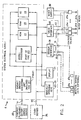
- FIG. 2 A preferred embodiment of an irrigation control system in accordance with the present invention is shown in Figure 2.
- An irrigation controller 1 (previously seen in Figure 1) operates under control of MICROPROCESSOR U2 (partial) executing programmed firmware that is resident in memories types ROM U4, RAM U5, and EE U9.
- the MICROPROCESSOR U2 (partial) communicates with MANUALLY OPERABLE KEYS 22-25 (previously seen in Figure 1) for receipt of data and control. It interfaces with DISPLAY 21 (previously seen in Figure 21) for the display of questions, parameters, and help messages to a human user/programmer (as detailed in previous section 2.0).
- the MICROPROCESSOR U2 (partial) of irrigation controller 1 optionally communicates externally through a SENSOR INTERFACE 26 of plugjack 16 (shown in Figure 1) to up to eight MOISTURE SENSING UNITS (optional) 27a-27h (shown in phantom line). This optional communication is the purpose of sensing soil moisture at up to eight locations.
- the MICROPROCESSOR U2 (partial) communicates through VALVE INTERFACE 28 of plugjack 13 (shown in Figure 1) to up to eight electromagnetically actuated CONTROL VALVES 29a-29h (shown in dashed lines).
- This communication is for the purpose of gating the flow of pressurized water from WATER SUPPLY 30 through a selected one of CONTROL VALVES 29a-29h at any one time to a corresponding one of WATERING HEADS 31a-31h (shown in dashed line).
- the MICROPROCESSOR U2 may optionally communicate through plugjack 15 (shown in Figure 1) to OTHER DEVICES 32 (shown in phantom line) for purposes of receiving the download of firmware programs, parameters, and/or commands.
- This interface need not be enabled to operate the irrigation controller 1, which in a preferred embodiment comes from the factory with that control program that is appendicized to this specification within its ROM memory U4 and EE memory U9, and which in the preferred embodiment may have all necessary parameters and control entered through MANUALLY OPERABLE KEYS 22-25. Indeed, if necessary firmware could be entered into controller 1 through it's MANUALLY OPERABLE KEYS 22-25.
- the digital interface to OTHER DEVICES 32 simply represents a less tedious way of communicating.
- the preferred embodiment of the controller 1 normally derives all its power, and all power for MOISTURE SENSING UNITS 27a-27h and CONTROL VALUES 29a-29h, during quiescent operation both day and night from radiant light energy impinging upon RADIANT ENERGY CONVERTING UNIT (includes ASIC U1) that comprises each of PVM1, U1, and ASSOCIATED CIRCUITRY.
- ASIC U1 includes ASIC U1
- PVM stands for photovoltaic module
- ASIC stands for application specific integrated circuits. All “U” designations stand for integrated circuit chips that may be referenced in Figure 7 (to be discussed).
- controller 1 is powered during its operation to accept user programming not by the RADIANT ENERGY CONVERTING UNIT PVM1, U1, and ASSOCIATED circuitry but rather by electrical connection through plugjack 14 (shown in Figure 1) to the POWERKEYTM PLUGGABLE BATTERY ENERGY SOURCE 33.
- This SOURCE 33 normally not a part of irrigation controller 1 during its quiescent operation, is shown neither in shadow line for being optional, nor in dashed line for being related to the controller 1 of the present invention but not part thereof. Rather, the POWERKEYTM PLUGGABLE BATTERY ENERGY SOURCE is shown in solid line in order to illustrate that for the purposes of programming the controller in accordance with the present invention it must be present.
- the SOURCE 33 supplies the greater power that the MICROPROCESSOR U2 (partial) needs to exit the predominantly somnolent (inactive) state that it only intermittently and momentarily leaves to effect irrigation control in accordance with the schedules, and to assume a high duty cycle at operation.
- the SOURCE 33 also supplies the power requirements of MANUALLY OPERABLE KEYS 22-25 and of DISPLAY 21 during user programming.
- the energy storage within the RADIANT ENERGY CONVERTING UNIT might suffice to permit user programming, it is unwise to deplete this energy storage to an undetermined amount (dependent on the length and adeptness of user programming) -- especially at night when no energy recovery is possible and especially when the controller is programmed to immediately begin controlling irrigation cycles. Instead, the SOURCE 33 actually charges the energy storage means within the RADIANT ENERGY CONVERTING UNIT, and always leaves the controller 1 fully powered and ready to control irrigation of the end of a user programming sequence.
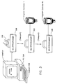
- a MULTIPROGRAMMER unit 300 is carried by a maintenance person 310. It contains all the programming instructions for up to 64 controllers. The MULTIPROGRAMMER unit 300 plugs into one of the IRRIGATION CONTROLLERs 1 through N whereupon the controller identifies itself to the MULTIPROGRAMMER unit and receives any new programming instructions intended uniquely for that controller. During the same communication episode the MULTIPROGRAMMER unit 300 receives and stores existing programs and history data from the controller. Later, back at the maintenance office, the MULTIPROGRAMMER unit 300 plugs into any personal computer PC 320 and reads out this information for verification and/or printout.
- the PC 320 runs software used for programming the IRRIGATION CONTROLLERs, and for emulating their function.
- the preferred software is the "6502 ASSEMBLER" for the 6502 microprocessor chip available from 2500AD Software, Inc., 17200 E. Ohio Drive, Aurora, Colorado 80017.
- the PC 320 may optionally emulate an IRRIGATION CONTROLLER, at least to the extent of accepting the same input control as an actual CONTROLLER and producing an output display that shows a display that would be upon an actual CONTROLLER's maintenance panel.
- the emulation further shows the valve actuations of the CONTROLLER and the times at which such occur.
- the emulation is based on inputting data from KEYBOARD 330 into the PC 320 and then into appropriate data storage addresses of an actual irrigation control program that is resident within the PC.
- the time-of-day clock memory storage location of the irrigation control program its set.
- the irrigation control program is run under its previously mentioned assembler. Certain memory storage locations that represent results of execution of the irrigation control program, such as the message buffer and/or the valve states, are then inspected.
- Custom graphics support can be provided for large users. In the case of a golf course, this would include course maps to allow the user to point to a subsystem he wants to work on rather than identifying it by code.
- FIG. 4 A pictorial diagram of the extension maintenance panel in operational use is shown in Figure 4.
- An irrigation controller 1 that is normally modified so as to not have a control panel 20 (shown in Figure 1) is mounted at the top of a post 2.
- the post 2 may be ten feet or greater in height so as to protect the irrigation controller from inadvertent or intentional damage.
- a RIBBON cable 40 connection of digital accessory connector 15 is extended interior to the hollow post 2 to JUNCTION BOX 41.
- the JUNCTION BOX 41 typically contains a coiled EXTENSION SERIAL CABLE, normally six feet in length. At the end of this cable an EXTENSION MAINTENANCE PANEL 42 is plugged.
- the EXTENSION MAINTENANCE PANEL 42 replicates the same, or equivalent, display 21 and pushbutton switches 21-25 that are within the control panel 20 (shown in Figure 1).
- the maintainer-user 43 may realize equivalent control and exercise of the irrigation controller 1 through EXTENSION MAINTENANCE PANEL 42 as is normally realized through control panel 20.
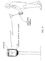
- a pictorial diagram of the radio-link central programming and monitoring system is shown in Figure 5.
- a radio-link module 50 mounts permanently below the controller 1 on the mounting pipe and serves as a transceiver for wireless communication between the controller and the radio-link CENTRAL STATION 51. This radio communication may be direct via path 52 or indirect via paths 53, 54 via a REMOTE RELAY RF UNIT 55.
- the radio-link CENTRAL STATION 51 may be a MASTER or a SATELLITE.
- a MASTER CENTRAL STATION contains a personal computer (PC) 58 that drives a local CENTRAL STATION RF UNIT 56.
- a SATELLITE CENTRAL STATION 51 contains only a CENTRAL STATION RF UNIT 56 that communicates with the PC 58 of another, MASTER, CENTRAL STATION 51 via the RF UNIT 56 of that station and the TELEPHONE LINES 57.
- the TELEPHONE LINES 57 do not, of course, carry an RF signal. They can, however, carry that information which is either received or broadcast.
- RF to telephone conversion is implemented through a modem located in the RF unit.
- a CENTRAL STATION 51 may be MOBILE, and mounted in a vehicle.
- the N irrigation controllers 1 may typically be programmed during drive-bys (insofar as the normal condition of the controller not to be energized is overcome).
- a tuned RF circuit within the controller may be sufficiently energized by strong RF radiation so as to produce a voltage capable of bringing the irrigation controller 1, and its attached radio-link module 50, awake.
- the radio-link CENTRAL STATION connects into same personal computer 58 that sends radio commands to the controller 1 via the radio link and receives information about the performance of the individual controllers and valves, along with data about soil moisture and other environmental parameters.
- the computer stores program information for all the controllers in the system in its memory and can operate the entire system remotely, via an emulated display panel identical to the on-site controllers. Sophisticated screen graphics and printer capabilities may be used to enhance operator convenience.
- FIG. 6 A pictorial diagram of a wireless remote test command system is shown in Figure 6.
- the remote test command system permits wireless remote "manual operation" of the valves and soil sensors of irrigation controller 1, in conjunction with an RF Test Adapter 60.
- This transceiver unit 60 is temporarily plugged into the controller 1 and receives "manual mode" commands from the hand-carried test commander 61. It also transmits soil sensor readings back to the hand-carried test commander 61.
- the portable hand-carried test commander 61 units are designed to be moved from controller to controller for installation, testing and maintenance purposes.
- the hand-carried test commander 61 is a hand held transceiver carried by the installer or maintenance person. It is used for remote "manual mode" or test sequence operation of the valves and reading of soil sensors without having to return to the controller. This feature is especially useful in large systems.
- the hand-carried test commander 61 can save the installer/maintenance person considerable time, and miles per day of unnecessary walking, in testing for sprinkler performance, leaks, obstructions, and in checking soil sensor performance.
- the hand-carried test commander 61 will be used for a variety of applications such as activating watering zones only as long as necessary to cleanout the irrigation system, speeding up testing and inspections, and pinpointing cracks in pipe by turning water on briefly from the repair site, without flooding the entire area and for verifying proper operation after repairs are completed.
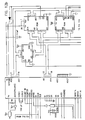
- FIG. 7a The schematic diagram of Figure 7a through Figure 7h, substantially a block diagram because the very substantial function of the circuit shown is contained in two Application Specific Integrated Circuits (ASICs) U1 (shown in Figure 8) and U2 (shown in Figure 10) -- shows the preferred embodiment of irrigation controller 1 (previously seen in Figures 1 and 2) in accordance with the present invention.
- ASICs Application Specific Integrated Circuits
- POWERKEYTM power source is a battery that is connected between terminals BAT + and BAT -.
- the POWERKEYTM power source (not shown) is always connected. Thereby the battery provides the considerable power necessary to energize the display LCD 1, and, importantly, operate the entire controller 1 at the high duty cycle necessary to conduct communications with the operator.
- the battery also serves to initially charge the capacitor power storage (both at a current limited rate) each time the POWERKEYTM battery power source is replugged to its receptacle 14 (shown in Figures 1 and 2). This insures that after each user interface communication the controller is always left in a fully charged condition.
- first ASIC U1 to manage the voltage and power levels of the irrigation controller, and, most particularly, to control the charging of SUPERCAPS C1, C2 by PVM 1 and the POWERKEYTM power source.
- the SUPERCAPS C1, C2 will automatically be charged by connection of the POWERKEYTM power source.
- the ASIC U1 operates to control this charging through a constant current source implemented by transistors Q3, Q4 and resistor R2.
- This constant current source is controlled by a switching regulator implemented from transistor Q2, inductance L1, diode D4, and capacitors C3, C4, all under the control of ASIC U1.
- the switching regulator and constant current source act jointly to pass, during the presence of bright sunshine or of the POWERKEYTM power source, up to 63 milliamperes through steering diode D3 to charge SUPERCAPS C1, C2.
- the diodes D1, D2 prevent discharge of the charged SUPERCAPS C1, C2.
- connections to the ASIC U1 that is used for power management and control include VDD 2.
- VDD 2 is the main +5 vdc power for the irrigation controller 1 and other components (such as CONTROL VALVES 29a-29h or MOISTURE SENSING UNITS 27a-27h both shown in Figure 2) to which it is attached in order to form an irrigation system.
- Signals BA and DX provide local control to the switching regulator and constant current source.
- NSL stands for system low voltage
- NSVL stands for system very low voltage
- NSH1 stands for the first shunt from the upper SUPERCAP
- NSH2 stands for the second shunt from the lower SUPERCAP
- NBP produces a battery present control signal.
- the output PULSE is a real time clock interrupt of 30 microseconds duration occurring each 1/2 millisecond.
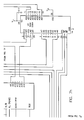
- the logical control function of the irrigation controller 1 is substantially implemented by digital ASIC U2, shown extending across each of Figures 7b, 7d, 7f, and 7h.
- the main switch control inputs S1-S6 to ASIC U2, used for operator programming of the irrigation controller 1, are from corresponding switches S1-S6 shown in Figure 7a.
- the switches S1-S6 respectively implement the stop, unused, unused, help, no, and ok switch control inputs to ASIC U2. These switches S1-S6 are called the MANUALLY OPERABLE KEYS 22-25 in Figure 2.
- ASIC U2 offers a total of 16 A/D channels, of which eight are internal and eight are external.
- the irrigation valve control, or drive, signals developed by ASIC U2 are brought to terminal block J2. This terminal block J2 is brought out to plugjack 13 shown in Figures 1 and 2.
- the ASIC U2 operates on firmware instructions, and on parameters, that are stored within both read only memory ROM U4 and in random access memory RAM U5.
- the ASIC U2 addresses both such memories through ADDRESS DECODER U7.
- the irrigation controller 1 is generally versatilely programmable, as well as parameterizable. Thus, many firmware instructions that ASIC U2 executes are present in RAM U5 and are loaded therein in accordance with user requirements. Other firmware instructions reside in ROM U4.
- the irrigation controller 1 in accordance with the present invention connects to still another programmable memory other than RAM U5 (shown in Figure 7h).
- This is Electrically Erasable (EE) 1024 bit serial memory U9.
- EE memory is particularly distinguished in that it will retain its informational contents in the total absence of power (unlike RAM U5). Yet it is alterable in its contents, unlike non-votile ROM U4.
- the 1024 bit serial memory U9 permits the field programming of secret codes, vital set up information, and other information that is desirably user specified (unlike the factory-programmed informational contents of ROM U4), wherein this information will desirably not be lost during any interruption of power to the controller.
- Circuits U6 (save for one unused spare gate shown in Figure 7c), U7, and U8 form a control interface of a standard type from ASIC U2 to the 1024 bit serial EE memory U9.
- address line AD0 powers up
- address line AD1 selects
- address line AD2 clocks serial data present on line AD3 into, 1024 bit memory U9.
- the single, serial, data output bit D0 of 1024 bit memory U9 is amplified in non-inverting element U10 and communicated to ASIC U2 as bit ADO upon its address bus.
- FIG. 8 shows the overall architecture of the first, U1, Application Specific Integrated Circuit (ASIC) used within the preferred embodiment of the irrigation controller in accordance with the present invention.
- ASIC Application Specific Integrated Circuit
- the detail function of ASIC U1 is essentially unimportant for the purposes of the present invention, and is included within this specification only for purposes of completeness.
- the photovoltaic module (PVM, shown in Figure 7a), SUPERCAPS C1 and C2 (shown in Figure 7a) and ASIC U1 (shown in Figure 7a) may be considered to simply be the implementation of a special form of a light-energized power supply.
- the general implementation of an a.c. or battery source power supply is, of course, routine in the electrical arts.
- SUPERCAPS very large supercapacitors
- the U1 ASIC device is designed to use minimal power while providing five (5) functions:
- Sampling capacitors are used to monitor the various capacitor and power supply voltages, allowing the use of only one comparator to conserve current.
- CrSi 100 k ⁇ / resistors are used to minimize analog currents.
- the voltage reference is trimmed using on-chip metal fuses.
- CMOS circuitry There are 3 potential 'most positive' voltages and two potential 'most negative' voltages, making substrate connections difficult. This is handled by using bipolar junction isolation that employs the isolated n- regions as separate CMOS substrates. This allows the CMOS circuitry to operate from several supplies, any one of which could be at the highest potential at different times.
- the logic generally runs from VSS1 (OV) to VDD2 (0-5V), level shifting where required.
- Analog references run from VSS1 to VDD1 (0-11V).
- Switching regulator components run from VSS2 (-.7 to +5.5 V) to VBAT (0 to 15 V).
- the upper shunt transistor is connected to a voltage which can range from 0 to VDD1 +0.7V.
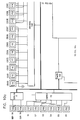
- FIG. 11 A block diagram of the preferred embodiment of the Multiprogrammer usable in the distributed multiple irrigation controller control management system of the present invention is shown in Figure 11.
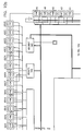
- Figures 12a through 12c A schematic diagram of the same Multiprogrammer unit is shown in Figures 12, consisting of Figures 12a through 12c.
- the Multiprogrammer unit 300 (previously seen in Figure 3) is based on both the ANALOG ASIC U1 and the DIGITAL ASIC U2 previously seen within the irrigation controller of Figure 7, and respectively individually illustrated in Figures 8 and 10.
- the ANALOG ASIC U1 connects to a BATTERY 70 which may be, but need not be, configured the same as the POWERKEYTM pluggable battery energy source.
- the ANALOG ASIC U1 operates to provide 5 volt dc regulated power to remaining components of the Multiprogrammer unit 300 from the power provided by the BATTERY 70.
- the BATTERY 70 connects through jack J1 terminals 2 and 7 to provide power to the irrigation controller when the multiprogrammer unit 300 is plugged thereto.
- the DIGITAL ASIC U2 containing the microprocessor type 6502, operates on a stored firmware program contained with ROM 71. This program causes the DIGITAL ASIC U2 to communicate through standard universal serial interface UART 72 type 65C51 across an interface I/F type RS232 73. This serial interface connects to a like serial interface port of a computer, particularly the personal computer PC 320 shown in Figure 3.
- the communication path through the RS232 I/F 73 permits the DIGITAL ASIC U2 to receive information that is subsequentially stored within RAM 74.
- the RAM 74 is nominally 512 K by 8 bits in size, and is of type 622S6. At this size it is capable of holding 64 complete programs as are uploaded to those IRRIGATION CONTROLLERs 1 (shown in Figure 3) to which the Multiprogrammer unit 300 at times connects.
- FIG. 12 shows the particular wired interconnection of the functional elements block diagrammed in Figure 11, and more particularly shows the interface between the Multiprogrammer unit 300 and the irrigation controller 1.
- the present invention has been taught in the context of electrical circuits that are fairly sophisticated for employing both a predominantly analog ASIC (ASIC UI) and a predominantly digital ASIC (ASIC U2), it should be understood that the functionality of the preferred embodiment of an irrigation controller in accordance with the present invention is readily realizable by diverse alternative designs.
- the core microprocessor of the preferred embodiment of the invention is 100% compatible with industry standard type 6502. All firmware appended to this specification will execute on a 6502 microprocessor, and is readily convertible to alternative microinstruction repertoires executing on alternative microprocessors.
- the circuits by which data is manually input to the microprocessor and displayed, and the control of irrigation valves, are, in the preferred embodiment of the invention, powered and sequenced to states of activity in a highly unique manner.
Abstract
Description
- The present invention concerns the coordinated programming and test control of multiple independent, but irrigation-function interrelated, programmable electronic irrigation controllers within an irrigation system.
- Large irrigation systems, such as those for golf courses and parks, typically use many dozens of independently operative irrigation controllers. Each irrigation controller controls a number of valves that gate the flow of irrigation water, typically to eight valves per controller. Because each irrigation controller must be electrically wired to all valves that it controls, it is infeasible to have the many hundreds or thousands of valves in a large area irrigation system controlled by a single controller.
- Although each irrigation controller is independent in its operation, the irrigation control exercised by multiple irrigation controllers is typically interrelated, and must be coordinated. This is because the piping of irrigation water to the stations, or valves, of a number of irrigation controllers is usually in series, one station to the next. A fundamental rule of irrigation control is that only such numbers of irrigation stations should be simultaneously enabled for irrigation watering as do not, resultant to the drop on hydrostatic pressure and flow caused by each "on" station, adversely affect irrigation watering pressures, flows, and patterns at any one(s) of the simultaneously enabled stations. Because most irrigation piping is of minimal diameter and cost consonant with the water flow and pressure requirements of a single irrigation station, application of the rule normally requires that only one irrigation station should be enabled any one time.
- Enabling one only irrigation station, or valve, to be on at one time among all the valves controlled by a single irrigation controller is merely a matter of the setup, or programming, of that one irrigation controller. However, if separate and independent irrigation controllers must be coordinated, as is typically required due to the plumbing of irrigation water, then matters become more difficult. A programmer/user of interrelated irrigation controllers must understand the hydrodynamic relationships of the valves controlled by each. These relationships may be several and may be at several hydrodynamic levels within a large irrigation system. In accordance with this understanding, the programmer/user must program irrigation at each irrigation controller in consideration of his/her programming of the other irrigation controllers.
- Even when the necessary coordination of irrigation control programming is kept track of on paper, its actual implementation is difficult and fraught with error. The irrigation controllers themselves are typically difficult and time consuming to program. They are required to be programmed where located, meaning in the field. The weather conditions under which the irrigation controllers must be programmed, and the caliber and diligence of the workers that must tend to the programming, are not always good. Considerable difficulty of coordination between irrigation controllers is experienced. It is hard to affect any appreciable change at any one controller until all controllers are reasonably well coordinated.
- These difficulties tend to impart a great deal of undesired rigidity to the entire irrigation programming process. The system wide reprogramming of an irrigation system because of variations in rainfall, seasonal variations, changed site requirements and numerous other reasons is often undesirably foregone simply because it is excessively difficult to plan, setup, or repeatedly setup coordinated irrigation control.
- One previous approach in dealing with the difficulties in the coordinated setup, or programming, of multiple independent but functionally interrelated irrigation controllers within a single irrigation system has been based on the establishment of one master and several satellite irrigation controllers. The master irrigation controller communicates with its satellite irrigation controllers to sequence their respective operations. Flexibility in scheduling is typically constrained by the nature of the sequential control of the satellite irrigation controllers. The expense of a wired communication network is incurred. The problem of coordinating multiple interrelated irrigation controllers is simply moved to a higher level because multiple master irrigation controllers may themselves now require coordinated set-up, now at typically increased complexity, one to another.
- From WO 86/05945, it is known a watering control system comprising a basic unit which is adapted to control a plurality of output control devices such as irrigation valves. The basic unit includes a module which is separately removable from the basic unit. The module may be moved to and connected with a computer for reprogramming the module from time to time so as to provide for different control periods.
- Further, from FR-A-2 371 005, it is known an irrigation system in which the irrigation controller comprises a microprocessor which is connected to a non-volatile memory. If necessary, the memory may be reprogrammed electrically.
- Finally, US-A-4 648 066 discloses a portable memory module for transferring configuration data from one programmable panel controller to another.
- The present invention contemplates (i) generating one or more programs for one or more potentially interrelated irrigation controllers at a central computer, (ii) downloading the one or more programs from the central computer into a transportable memory device, (iii) transporting, and communicatively connecting, the transportable memory device to each one of the one or more potentially interrelated irrigation controllers in series, and (iv) uploading a program from the transportable memory device into each one of the one or more irrigation controllers.
- The central program generation preferably transpires on a digital computer, typically on a personal computer. The computer permits the assembly (or compilation) of the programs that will be executed by the actual irrigation controllers. Each irrigation controller preferably contains a microprocessor, nominally a type 6502 contained within an Application Specific Integrated Circuit, and executes firmware programs to effect irrigation control. The personal computer generates these firmware programs by running commercially available assemblers (or compilers) for this popular microprocessor. These programs are individualized as required or desired to each irrigation controller.
- Moreover, the personal computer is preferably programmed so as to emulate the irrigation controllers both individually and collectively. This emulation is particularly of the manual input control and, in the form a display, the valve control and/or displays that would be produced by an actual irrigation controller as it would execute a particular actual program. The personal computer does not produce control signals to valves during its emulation of an irrigation controller, although it could do so. It is sufficient for the purposes of the present invention that the personal computer should merely emulate the responses of an irrigation controller as it executes a particular program.
- Because each irrigation controller is entirely controlled by only four pushbutton switches (OK/YES, NO, HELP, and STOP), because each controller generates only a modest number of relatively short messages and the on/off control of only eight valves, and because each controller runs firmware that is easily emulated in execution by the personal computer meanwhile that the controller's emulation need not be (and is usually not) conducted in real time, the emulation of one or more irrigation controllers by the personal computer is straightforward. This simultaneous emulation of one or more controllers permits debug of the control program of any one controller and, importantly, visibility (on the screen of the personal computer's monitor) of the diurnal irrigation control arising from multiple interrelated controllers. A central programmer's task in coordinating a number of interrelated irrigation controllers for the control of irrigation within a single irrigation system is thus much facilitated.
- The transportable memory device preferably interfaces to the personal computer by a standard digital serial interface type RS-232C, and to each irrigation controller by a custom digital interface. The custom digital interface is functionally distinguished by starting automatically upon physical electrical connection of the memory device and an irrigation controller, by having the controller automatically identify itself to the memory device and vice versa, and by automatically uploading the appropriate program from the memory device into each individual controller.
- The memory device can preferably carry up to sixty-four (64) complete irrigation control programs simultaneously. It preferably employs the same microprocessor (type 6502 contained within an Application Specific Integrated Circuit) that is also used within the irrigation controller. The automated, microprocessor-managed, interchange of unit identities and the automated transfer of an appropriate program minimizes any required human involvement and/or skills at the controllers' field sites, and permits the complex programmed setup of many irrigation controllers to be quickly and easily accomplished by unskilled field workers.
- The irrigation controllers each keep a time-of-day clock. Each controls the conduct of irrigation in accordance with schedules computed by its microprocessor from execution of its individually associated firmware program. Because the programs that were generated at the central source are coordinated for the timed control of irrigation at many dozens or hundreds of stations (valves) within an irrigation system, the actual timed irrigation control effected by the irrigation controllers is also so coordinated. In particular, a number of physically separate and independent irrigation controllers that are interrelated in their required functional control of irrigation may readily be coordinated so as to respond as a single virtual controller. For example, three irrigation controllers controlling eight stations each may readily be coordinated in operation to act as one virtual controller controlling twenty-four stations. The concept of virtual irrigation controllers -- which virtual controllers are readily created and programmed at the personal computer -- much facilitates the ease with which a programmer may think about the programming of coordinated irrigation control within an irrigation system.
- The present invention further contemplates that the irrigation controllers should load information into the portable memory device, and that this information should be carried back to the central station personal computer to be offloaded for analysis, verification, and/or printout. The loaded information commonly comprises both the existing, previous, firmware program to that one being uploaded (if any is) plus data in the form of actual historic operational occurrences (normally for the prior 30 days). Ability to recover the existing irrigation controller firmware program permits the study and analysis of programs installed in the field, or the verification whether or not programs previously believed to have been installed were so installed in fact. The ability to recover actual historical data permits analysis of irregular occurrences, improvement of irrigation watering amounts and schedules in accordance with actual site conditions (especially as sensed by optional moisture sensors), and validation of proper irrigation system performance.
- The present invention still further contemplates that other devices than the transportable memory device should be selectively connectable to the custom digital interface of the irrigation controller. Each device identifies itself to the irrigation controller and to its microprocessor operating under firmware program control. The irrigation controller thus normally requires no manual intervention other than physical connection of each device in order to cooperatively interoperate with such device.
- A portable maintenance panel extender device connects a substitutionary or additional maintenance panel for that maintenance panel that is customarily under a cover plate of the irrigation controller. One benefit so derived is the capability of placing the irrigation controller, which is light-energized, upon a high pole where it is substantially immune from vandalism while maintaining the connection for this portable extended maintenance panel, normally within a strong locked enclosure, at a height whereat it may be conveniently accessed.
- A radio-linked central programming system for multiple irrigation controllers uses a radio transceiver that is connected to each controller's digital interface port. A central, or mobile radio transceiver sends and receives controller specific information at prescheduled times, typically diurnally. The irrigation controller typically does not have much stored energy to power its connected radio transceiver. The radio transceiver is correspondingly inactive at all times save for prescheduled time intervals when an individual controller may be addressed.
- A wireless remote test command system permits manual test operation of the valves connected to an irrigation controller. The valves that are connected to an irrigation controller may generally be locally exercised through the maintenance panel of the irrigation controller. In the remote test command system, a self-powered transceiver is temporarily plugged into the digital interface of the irrigation controller. A hand-held transceiver that is carried by an installer or maintenance person is used to test the operation of valves (and the readings of optional soil sensors, if implemented) without the necessity of physically returning to the controller. Considerable time and walking may be saved in testing for sprinkler and pipe performance, for leaks or obstructions, in checking soil sensor performance, and in validating all repairs.
- These and other aspects and attributes of the present invention will become increasingly clear upon reference to the following drawings and accompanying specification wherein:
-
- Figure 1 is a pictorial diagram of an irrigation controller in accordance with the present invention;
- Figure 2 is a block diagram of an irrigation system in accordance with the present invention including the irrigation controller illustrated in Figure 1;
- Figure 3 is a pictorial diagram of a multiprogrammer unit in accordance with the present invention in use to transport programs to the irrigation controller;
- Figure 4 is a pictorial diagram of a maintenance panel extender to the irrigation controller;
- Figure 5 is a pictorial diagram of a radio-linked central programming system for communication with irrigation controllers;
- Figure 6 is a pictorial diagram of a remote test command system for exercising and testing irrigation controllers;
- Figure 7, consisting of Figure 7a through Figure 7h, is a schematic diagram of the preferred embodiment of an irrigation controller in accordance with the present invention;
- Figure 8 is a block diagram of a first, U1, Application Specific Integrated Circuit (ASIC) used in the preferred embodiment of an irrigation controller in accordance with the present invention;
- Figure 9a is a simplified electrical schematic diagram of the sampling capacitor array and switches used in ASIC U1;
- Figure 9b is a simplified electrical schematic diagram of a sampling comparator used in ASIC U1;
- Figure 9c is a simplified electrical schematic diagram of a step-up DC-to-DC Converter used in the switching regulator of ASIC U1;
- Figure 10, consisting of Figure 10a through Figure 10d, is a block diagram of a second, U2, Application Specific Integrated Circuit (ASIC) used in the preferred embodiment of an irrigation controller in accordance with the present invention.
- Figure 11 is a schematic block diagram of a preferred embodiment of the multiprogrammer previously seen in Figure 3.
- Figure 12 is a detail schematic diagram of the preferred embodiment of the multiprogrammer previously seen in Figures 3 and 11.
- The present invention is embodied in a system for the programming and test control of an irrigation controller. The irrigation controller is preferably light-energized for the control of irrigation through eight stations, or valves, of up to 128 total cycles per day. The irrigation controller is spoken of as being "light-energized" and (along with the irrigation valves that it controls) to embody "Light-Energized Irrigation Technology" (LEIT). This description is in lieu of describing, for example, the controller to be "solar powered" because it employs an extremely small area light (solar) collector. Resultant to the small energy collected, the controller uses extremely little energy for all irrigation functions, including control of up to eight (8) valves. The acronym LEIT when applied to irrigation controllers is a trademark of Solatrol, Inc. (assignee of the present invention), i.e., LEIT™ Irrigation Controllers.
- No electrical power input is required. Light energy required is 0.4 milliwatts/sq cm incident light for a minimum of 7 hrs/day. This is approximately equivalent to one tenth of the amount of light at 55° northern latitude (e.g., in Canada) on a cloudy winter's day.
- The power for the controller's display (when actuated) is derived from a POWERKEY™ (trademark of Solatrol, Inc.) power source. The POWERKEY™ power source packages a 9-volt alkaline battery that is used to energize the Liquid Crystal Display (LCD) of the controller during installation and programming.
- The signal output of the controller to its controlled valves is 3.5 volts DC, 0.04 amps for .04 seconds. No circuit breaker and no transformer are required.
- Up to 8 valves (including up to 4 Master Valves) may be connected to each controller. Up to 8 electronic soil moisture sensors or optionally, other compatible electronic sensing devices, may also be connected to each controller.
- A user-defined emergency backup program and critical system parameters are stored in non-volative memory in case of memory loss from prolonged light interruption; no batteries are needed.
- The preferred embodiment of a LEIT Irrigation controller in accordance with the present invention interfaces with other devices for the loading of irrigation control programs and the manual exercise of irrigation valves and sensors.
- A POWERKEY™ (trademark of Solatrol, Inc.) power source is a combination keyring and keyfob-cased battery for powering the irrigation controller and its display during programming and/or interactive operation. The POWERKEY™ power source is manually plugged to the controller. It provides power to the controller for its very first use, and thereafter during each episode of the programming/parameterization of the controller's operation and/or the reviewing of data in the controller's memory. The POWERKEY™ power source also provides power to the built-in illumination of the controller's display and control switches. The power source that is used during operation of the controller to control irrigation may be the POWERKEY™ power source if it is still pluggably attached (an abnormal condition), but is normally light (even extremely dim light, such as moonlight) that falls upon the controller.
- A Multiprogrammer™ unit plugs into the digital interface of the controller for uploading and downloading the irrigation watering program that is executed by the controller. The Multiprogrammer unit simultaneously holds the programs for up to 64 controllers.
- A remote test command assembly mounts in position as a replacement controller face-plate. It plugs into the digital interface of the controller and receives signals from a hand-held transceiver carried by a maintainer in order to allow wireless remote "manual" operation of the controllers valves and sensors. This remote operation characteristically occurs while the maintainer inspects the valve or sensor locations.
- An extension maintenance panel substitutes for, or replicates (as is specified and configured during build of the irrigation controller) the normal maintenance and control panel of the irrigation controller. The extension maintenance panel is remotely situated from the controller in a position where it may be accessed. The controller is typically located atop a high pole so as to collect light while being isolated from damage due to accident or vandalism. The extension maintenance and control panel contains only four switches and a display. It interfaces to the controller's digital interface.
- A radio-link module mounts permanently to the controller at its digital interface. The module acts as a transceiver for wireless communication between the controller and a radio-link central system. The same program and data information is normally communicated by radio as is alternatively carried in the Multiprogrammer unit.
- Only one of the Multiprogrammer unit, the remote test command assembly, or the radio-link central module attaches to the irrigation controller at its digital interface at one time. Each device identifies itself to the controller, and the individual controller (of which their may be many in an irrigation system) is likewise identified to the device. The Multiprogrammer unit, the extension maintenance panel, the radio-link module and the remote test command assembly provide their own power.
- The controller-mounted transceiver of the radio link module is energized but momentarily on a daily schedule. Messages communicated by radio normally include operating programs to be downloaded into the controller, or historical data to be uploaded to the central station. If a message is to be passed, then a controller's radio-link module will remain energized for the duration of the message. Otherwise the powering of the radio link is only momentary.
- Up to 8 optional soil moisture sensor units can connect to the controller to give precise irrigation system control based on readings of available soil moisture tension, or optionally, percentage soil saturation.
- The preferred embodiment of an irrigation controller in accordance with the present invention is light-energized with a built-in incident light collector. It exhibits sufficient energy storage to drive a custom CMOS ultra-low-power microcomputer with 32K RAM memory and to cycle up to eight (8) ultra-low-power irrigation valves up to sixteen (16) times each per twenty-four (24) hour period. This provides complete independence from any need for AC power, saving on energy and installation costs and permitting the controller to be located closer to the valves.
- An easy to read two-line LCD display with automatic prompting is implemented. The user is guided through the programming process with easy to understand two-line "prompts," thus substantially eliminating confusion, mistakes, and requirements to repeatedly reference printed or human authority.
- Two-button programming with "best guess" defaults is used for all settings. All programming is done by answering simple questions with OK or NO answers. The controller automatically gives the user "best guess" defaults where applicable.
- An on-line help feature gives directions and information for each operational mode and parameter insertion. These on-line help messages are available at any time by pressing a HELP key.
- The design is modular in that multiple 8-valve-station controller units can be integrated together. The individual 8-valve-station controller units can be networked together into optionally radio-linked centrally controlled systems, or, alternatively, multiple unrelated controllers on various sites can be centrally managed by optional multi-programming equipment.
- Each of the 8 stations for a single controller unit can be independently programmed within one of six different runtime modes (Mini, Autosplit, Ration, One-Time, and Special. This gives the Irrigation Controller great programming flexibility. Options for (i) simplified "Mini" setups, (ii) "Autosplit" setups with automatically programmed split cycles and sequential non-overlapping operation, (iii) "Ration" setups for odd/even (day of month) water rationing, (iv) "ISC" setups with complete independence between stations, (v) "Special" setup for lights, fountains, and pump-start relays, (vi) periodic or one-time "Add-on Soak Cycle" setups, and (vii) for multiple "Add-on Syringe Cycle" setups are implemented.
- Controller timing control of the irrigation valves is from 1 minute to 240 minutes in one minute increments. Thus one minute precision in starting or stopping irrigation is combined with the ability to set watering durations of up to 4 hours for each start time. One-time or periodic "soak cycles" can have a duration of up to 8 hours.
- A calendar is maintained based on "perpetual calendar" data in permanent memory. Schedules may be established for specific days or every "so many" days. This permits flexible day cycles for irrigation, and allows different stations to operate on different day cycles.
- Up to 128 automatic starts per day are enabled, thereby meeting the most demanding applications.
- The controller's split cycle capability permits watering times to be split into up to 16 substantially equal increments. This minimizes runoff and puddling by splitting the programmed watering duration into shorter cycles each of which is separated by a programmable minimum "off" time.
- A System Budgeting Factor of 10 to 200% acts to determine the numbers of split cycles. The System (water) Budgeting Factor increases or decreases the number of split cycles instead of acting as a total duration multiplier which can lead to runoff and puddling. Monthly budgeting with preset default values for each month is also available. This allows an entire year's scheduling to be set up.
- An Integrated Moisture Sensor control with programmable "wet" and "dry" trigger levels is optionally implemented for each valve station. This keeps the soil moisture level for each valve within the optimal range for the growth of the type of vegetation being watered by that valve, instead of merely using the optional moisture sensors as switches to override cycle starts.
- Automatic sequential program generation permits "Excluded Time Intervals". The controller automatically generates a sequential matrix of start times for all active valves and split irrigation cycles based on user input for determined total watering durations by valve, either site information selection or operator entered number of split cycles, and on any user-defined "Excluded Time Intervals" when no watering is desired.
- For very simple applications a "Mini" setup is available. This simple setup mode is extremely easy to use, and it is designed for applications where some of the more sophisticated features of the controller are not needed.
- Another option, the "Special setup", can be used for control of non-valve devices such as pumps, or lighting equipment.
- One-time or periodic "Soak" cycles can be overlaid on any regular watering program. This feature can be used for watering in fertilizer, for periodically deep watering trees and shrubs in turf areas, and for periodically leaching salts in drip applications.
- Multiple daily cooling or frost-wipe "Syringe" cycles can be overlaid on any regular watering program for any preprogrammed month(s) when needed. These cycles help prevent wilting and scorching of plant materials during hot summer months or damage from freezing or morning dew in cold weather months.
- Even and odd days can be automatically excluded as watering days in the "Ration" setup mode. This allows for odd/even water rationing schedules to be easily programmed where this is mandated by law.
- A programmable "Delay Start" permits watering to be suspended for up to 14 days during rainy weather, and at the end of the programmed "Rain Delay" the regular watering schedule will automatically resume.
- A special "View Info" mode allows the user to review all settings or to view an event report which displays the controller history and current operational setup. This permits the user to easily review the current controller settings or to view a list of the last 128 events (watering cycles, program changes, etc.) in chronological order starting from the earliest event.
- Built-in wire continuity and short testing, system self-test and report functions are implemented. The user is alerted if shorted or open valve wires exist, and the unit performs a self-diagnostic test when requested.
- A "Test Sequence" allows each valve to be operated in sequence for one to thirty minutes. This allows the irrigation system to be easily periodically tested. A STOP key lets the operator immediately stop the test sequence if broken sprinklers or pipes are found.
- Both valve stations and sensors can be operated automatically, semi-automatically, or manually. In semi-automatic mode, all or selected valves can be run once using the "One-Time" setup. This allows the user to do a one-time soak for watering in fertilizer or new plantings. The controller then automatically reverts to the automatic "Run" mode.
- Three level access codes provide security and render the controller useless if stolen. Separate codes for gardeners, supervisors, and factory personnel insure that only authorized individuals can change the controller settings, and that codes can be easily changed as operating personnel change.
- The preferred embodiment of an irrigation controller in accordance with the present invention uses Light Energized Irrigation Technology (LEIT™). It can operate with the amount of incident light available in northern latitudes on a worst-case cloudy winter's day without needing any of the batteries, external solar panels, or the A.C. power connections required for traditional controllers. It is also extremely flexible and versatile in its operation.
- A diagrammatic view of the preferred embodiment of the controller, with its cover plate removed and operator's panel area exposed, is shown in Figure 1.
Controller 1 is typically attached to post 2. A photovoltaic device 10 (not shown) is located undertransparent lid 11 tocase 12. - Various electrical connectors are presented. A
valve connector block 13 permits electrical connection by wires (not shown) to up to eight (8) electromagnetically actuated valves. Acontrol key socket 14 accepts a pluggable POWERKEY™ power source (not shown), being a 9 vdc battery suitably packaged so as to plug intosocket 14. Adigital accessory connector 15 permits communication connection to a Multiprogramming unit (not shown) that may upload and download programs into the controller 1 (among other alternative ways of programming controller 1). Theconnector 15 is a standard type, and may, under firmware control withincontroller 1, interface to further devices. Asensor connector block 16 permits connection of up to eight (8) optional soil moisture sensors or other sensing devices. These soil moisture sensors, and the control proceeding therefrom, are not taught within this specification for being unimportant to the present invention. - A
control panel 20 contains a liquid crystal display (LCD) 21 for showing information, questions, and directives. Thecontrol panel 20 also contains pushbutton switches 22-25. ASTOP switch 22 stops thepresent controller 1 operation and turns off any valves previously turned on. AHELP switch 23 causes thecontroller 1 to display more information and/or instructions, keyed to the current operation or displayed questions, inLCD 21. TheNO switch 24 and theOK switch 25 are used to answer controller-presented questions about the installation and the parameters of irrigation (e.g., the watering schedule) and to enable selectable readout of controller stored data. - The
controller 1 is controlled in its operation by firmware running on a special Application Specific Integrated Circuit (ASIC) that includes a microprocessor. The explanation of thecontroller 1 hardware is contained in major sections 3-5 of this specification. Thismajor section 2 deals with the user interface tocontroller 1, and serves to show its many unique aspects in accordance with the present invention. - The term "programming" used throughout this specification includes actions performed at the operator interface to the
controller 1 -- actions normally but not necessarily performed in the field -- by which thecontroller 1 is parameterized and directed in its programmed operation. The firmware itself is, of course, also "programmed". In some cases the act of "programming" at the operator's panel will alter the flow, as well as the parameters used, within the firmware; thus constituting a form of "programming" at the process control level. The word "programming" is used to refer to the total compendium of operator/programmer interface to, and control of,irrigation controller 1. The word includes actions more exactingly thought of as parameterization (typically done in the field), as well as actions more exactingly thought of as coding (typically done in the factory or depot). - A preferred embodiment of an irrigation control system in accordance with the present invention is shown in Figure 2. An irrigation controller 1 (previously seen in Figure 1) operates under control of MICROPROCESSOR U2 (partial) executing programmed firmware that is resident in memories types ROM U4, RAM U5, and EE U9. The MICROPROCESSOR U2 (partial) communicates with MANUALLY OPERABLE KEYS 22-25 (previously seen in Figure 1) for receipt of data and control. It interfaces with DISPLAY 21 (previously seen in Figure 21) for the display of questions, parameters, and help messages to a human user/programmer (as detailed in previous section 2.0).
- The MICROPROCESSOR U2 (partial) of
irrigation controller 1 optionally communicates externally through aSENSOR INTERFACE 26 of plugjack 16 (shown in Figure 1) to up to eight MOISTURE SENSING UNITS (optional) 27a-27h (shown in phantom line). This optional communication is the purpose of sensing soil moisture at up to eight locations. The MICROPROCESSOR U2 (partial) communicates throughVALVE INTERFACE 28 of plugjack 13 (shown in Figure 1) to up to eight electromagnetically actuatedCONTROL VALVES 29a-29h (shown in dashed lines). This communication is for the purpose of gating the flow of pressurized water fromWATER SUPPLY 30 through a selected one ofCONTROL VALVES 29a-29h at any one time to a corresponding one of WATERING HEADS 31a-31h (shown in dashed line). - The MICROPROCESSOR U2 (partial) may optionally communicate through plugjack 15 (shown in Figure 1) to OTHER DEVICES 32 (shown in phantom line) for purposes of receiving the download of firmware programs, parameters, and/or commands. This interface need not be enabled to operate the
irrigation controller 1, which in a preferred embodiment comes from the factory with that control program that is appendicized to this specification within its ROM memory U4 and EE memory U9, and which in the preferred embodiment may have all necessary parameters and control entered through MANUALLY OPERABLE KEYS 22-25. Indeed, if necessary firmware could be entered intocontroller 1 through it's MANUALLY OPERABLE KEYS 22-25. The digital interface toOTHER DEVICES 32 simply represents a less tedious way of communicating. - The preferred embodiment of the
controller 1 normally derives all its power, and all power forMOISTURE SENSING UNITS 27a-27h andCONTROL VALUES 29a-29h, during quiescent operation both day and night from radiant light energy impinging upon RADIANT ENERGY CONVERTING UNIT (includes ASIC U1) that comprises each of PVM1, U1, and ASSOCIATED CIRCUITRY. "PVM" stands for photovoltaic module and "ASIC" stands for application specific integrated circuits. All "U" designations stand for integrated circuit chips that may be referenced in Figure 7 (to be discussed). - The preferred embodiment of
controller 1 is powered during its operation to accept user programming not by the RADIANT ENERGY CONVERTING UNIT PVM1, U1, and ASSOCIATED circuitry but rather by electrical connection through plugjack 14 (shown in Figure 1) to the POWERKEY™ PLUGGABLEBATTERY ENERGY SOURCE 33. ThisSOURCE 33, normally not a part ofirrigation controller 1 during its quiescent operation, is shown neither in shadow line for being optional, nor in dashed line for being related to thecontroller 1 of the present invention but not part thereof. Rather, the POWERKEY™ PLUGGABLE BATTERY ENERGY SOURCE is shown in solid line in order to illustrate that for the purposes of programming the controller in accordance with the present invention it must be present. - This required presence is because the
SOURCE 33 supplies the greater power that the MICROPROCESSOR U2 (partial) needs to exit the predominantly somnolent (inactive) state that it only intermittently and momentarily leaves to effect irrigation control in accordance with the schedules, and to assume a high duty cycle at operation. TheSOURCE 33 also supplies the power requirements of MANUALLY OPERABLE KEYS 22-25 and ofDISPLAY 21 during user programming. Although the energy storage within the RADIANT ENERGY CONVERTING UNIT might suffice to permit user programming, it is unwise to deplete this energy storage to an undetermined amount (dependent on the length and adeptness of user programming) -- especially at night when no energy recovery is possible and especially when the controller is programmed to immediately begin controlling irrigation cycles. Instead, theSOURCE 33 actually charges the energy storage means within the RADIANT ENERGY CONVERTING UNIT, and always leaves thecontroller 1 fully powered and ready to control irrigation of the end of a user programming sequence. - The preferred embodiment of a system for delivering programs from a central program generation device to one or more independent irrigation controllers is pictorially illustrated in Figure 3.
- A
MULTIPROGRAMMER unit 300 is carried by amaintenance person 310. It contains all the programming instructions for up to 64 controllers. TheMULTIPROGRAMMER unit 300 plugs into one of theIRRIGATION CONTROLLERs 1 through N whereupon the controller identifies itself to the MULTIPROGRAMMER unit and receives any new programming instructions intended uniquely for that controller. During the same communication episode theMULTIPROGRAMMER unit 300 receives and stores existing programs and history data from the controller. Later, back at the maintenance office, theMULTIPROGRAMMER unit 300 plugs into anypersonal computer PC 320 and reads out this information for verification and/or printout. - The
PC 320 runs software used for programming the IRRIGATION CONTROLLERs, and for emulating their function. The preferred software is the "6502 ASSEMBLER" for the 6502 microprocessor chip available from 2500AD Software, Inc., 17200 E. Ohio Drive, Aurora, Colorado 80017. ThePC 320 may optionally emulate an IRRIGATION CONTROLLER, at least to the extent of accepting the same input control as an actual CONTROLLER and producing an output display that shows a display that would be upon an actual CONTROLLER's maintenance panel. The emulation further shows the valve actuations of the CONTROLLER and the times at which such occur. - The emulation is based on inputting data from
KEYBOARD 330 into thePC 320 and then into appropriate data storage addresses of an actual irrigation control program that is resident within the PC. The time-of-day clock memory storage location of the irrigation control program its set. The irrigation control program is run under its previously mentioned assembler. Certain memory storage locations that represent results of execution of the irrigation control program, such as the message buffer and/or the valve states, are then inspected. - This series of operations can all be done piecemeal under the operating system of
PC 320, normally under the MS-DOS operating system. However, the necessary interfacing is normally accomplished by use of a small executive program. The executive program leads the operator through those same programming steps which are used in setting up a controller on-site, but also employs the computer's screen graphics and printer capabilities in order to give the operator more information with less effort. The executive program also facilitates user archiving of program and system histories. - Custom graphics support can be provided for large users. In the case of a golf course, this would include course maps to allow the user to point to a subsystem he wants to work on rather than identifying it by code.
- An electrical schematic of a preferred embodiment of
MULTIPROGRAMMER 300 is discussed in conjunction with Figure 11. - A pictorial diagram of the extension maintenance panel in operational use is shown in Figure 4. An
irrigation controller 1 that is normally modified so as to not have a control panel 20 (shown in Figure 1) is mounted at the top of apost 2. Thepost 2 may be ten feet or greater in height so as to protect the irrigation controller from inadvertent or intentional damage. ARIBBON cable 40 connection of digitalaccessory connector 15 is extended interior to thehollow post 2 toJUNCTION BOX 41. TheJUNCTION BOX 41 typically contains a coiled EXTENSION SERIAL CABLE, normally six feet in length. At the end of this cable anEXTENSION MAINTENANCE PANEL 42 is plugged. - The
EXTENSION MAINTENANCE PANEL 42 replicates the same, or equivalent,display 21 and pushbutton switches 21-25 that are within the control panel 20 (shown in Figure 1). The maintainer-user 43 may realize equivalent control and exercise of theirrigation controller 1 throughEXTENSION MAINTENANCE PANEL 42 as is normally realized throughcontrol panel 20. - A pictorial diagram of the radio-link central programming and monitoring system is shown in Figure 5. A radio-
link module 50 mounts permanently below thecontroller 1 on the mounting pipe and serves as a transceiver for wireless communication between the controller and the radio-link CENTRAL STATION 51. This radio communication may be direct viapath 52 or indirect viapaths RELAY RF UNIT 55. - The radio-
link CENTRAL STATION 51 may be a MASTER or a SATELLITE. A MASTER CENTRAL STATION contains a personal computer (PC) 58 that drives a local CENTRALSTATION RF UNIT 56. Alternatively, aSATELLITE CENTRAL STATION 51 contains only a CENTRALSTATION RF UNIT 56 that communicates with thePC 58 of another, MASTER,CENTRAL STATION 51 via theRF UNIT 56 of that station and theTELEPHONE LINES 57. The TELEPHONE LINES 57 do not, of course, carry an RF signal. They can, however, carry that information which is either received or broadcast. RF to telephone conversion is implemented through a modem located in the RF unit. - A
CENTRAL STATION 51 may be MOBILE, and mounted in a vehicle. In such a case theN irrigation controllers 1 may typically be programmed during drive-bys (insofar as the normal condition of the controller not to be energized is overcome). Typically a tuned RF circuit within the controller may be sufficiently energized by strong RF radiation so as to produce a voltage capable of bringing theirrigation controller 1, and its attached radio-link module 50, awake. - The radio-link CENTRAL STATION connects into same
personal computer 58 that sends radio commands to thecontroller 1 via the radio link and receives information about the performance of the individual controllers and valves, along with data about soil moisture and other environmental parameters. The computer stores program information for all the controllers in the system in its memory and can operate the entire system remotely, via an emulated display panel identical to the on-site controllers. Sophisticated screen graphics and printer capabilities may be used to enhance operator convenience. - A pictorial diagram of a wireless remote test command system is shown in Figure 6. The remote test command system permits wireless remote "manual operation" of the valves and soil sensors of
irrigation controller 1, in conjunction with anRF Test Adapter 60. Thistransceiver unit 60 is temporarily plugged into thecontroller 1 and receives "manual mode" commands from the hand-carriedtest commander 61. It also transmits soil sensor readings back to the hand-carriedtest commander 61. The portable hand-carriedtest commander 61 units are designed to be moved from controller to controller for installation, testing and maintenance purposes. - The hand-carried
test commander 61 is a hand held transceiver carried by the installer or maintenance person. It is used for remote "manual mode" or test sequence operation of the valves and reading of soil sensors without having to return to the controller. This feature is especially useful in large systems. The hand-carriedtest commander 61 can save the installer/maintenance person considerable time, and miles per day of unnecessary walking, in testing for sprinkler performance, leaks, obstructions, and in checking soil sensor performance. The hand-carriedtest commander 61 will be used for a variety of applications such as activating watering zones only as long as necessary to cleanout the irrigation system, speeding up testing and inspections, and pinpointing cracks in pipe by turning water on briefly from the repair site, without flooding the entire area and for verifying proper operation after repairs are completed. - A preferred embodiment of an irrigation control system in accordance with the present invention has been described in connection with Figure 2.
- The schematic diagram of Figure 7a through Figure 7h, substantially a block diagram because the very substantial function of the circuit shown is contained in two Application Specific Integrated Circuits (ASICs) U1 (shown in Figure 8) and U2 (shown in Figure 10) -- shows the preferred embodiment of irrigation controller 1 (previously seen in Figures 1 and 2) in accordance with the present invention.
- Commencing in Figures 7a and 7c, primary power is provided to the irrigation controller in accordance with the present invention by
photovoltaic module PVM 1 or, alternatively, by a POWERKEY™ power source. The POWERKEY™ power source is a battery that is connected between terminals BAT + and BAT -. During programming of theirrigation controller 1 the POWERKEY™ power source (not shown) is always connected. Thereby the battery provides the considerable power necessary to energize thedisplay LCD 1, and, importantly, operate theentire controller 1 at the high duty cycle necessary to conduct communications with the operator. The battery also serves to initially charge the capacitor power storage (both at a current limited rate) each time the POWERKEY™ battery power source is replugged to its receptacle 14 (shown in Figures 1 and 2). This insures that after each user interface communication the controller is always left in a fully charged condition. - During normal, quiescent, operation all low-power CMOS circuitry and the low-power valves are energized by energy stored in supercapacitors (SUPERCAPS) C1, C2. It is the function of first ASIC U1 to manage the voltage and power levels of the irrigation controller, and, most particularly, to control the charging of SUPERCAPS C1, C2 by
PVM 1 and the POWERKEY™ power source. The SUPERCAPS C1, C2 will automatically be charged by connection of the POWERKEY™ power source. The ASIC U1 operates to control this charging through a constant current source implemented by transistors Q3, Q4 and resistor R2. This constant current source is controlled by a switching regulator implemented from transistor Q2, inductance L1, diode D4, and capacitors C3, C4, all under the control of ASIC U1. The switching regulator and constant current source act jointly to pass, during the presence of bright sunshine or of the POWERKEY™ power source, up to 63 milliamperes through steering diode D3 to charge SUPERCAPS C1, C2. The diodes D1, D2 prevent discharge of the charged SUPERCAPS C1, C2. - Continuing in Figure 7a, connections to the ASIC U1 that is used for power management and control include
VDD 2.VDD 2 is the main +5 vdc power for theirrigation controller 1 and other components (such asCONTROL VALVES 29a-29h orMOISTURE SENSING UNITS 27a-27h both shown in Figure 2) to which it is attached in order to form an irrigation system. Signals BA and DX provide local control to the switching regulator and constant current source. The abbreviation NSL stands for system low voltage, NSVL stands for system very low voltage, NSH1 stands for the first shunt from the upper SUPERCAP, NSH2 stands for the second shunt from the lower SUPERCAP, and NBP produces a battery present control signal. The output PULSE is a real time clock interrupt of 30 microseconds duration occurring each 1/2 millisecond. - The logical control function of the
irrigation controller 1 is substantially implemented by digital ASIC U2, shown extending across each of Figures 7b, 7d, 7f, and 7h. The main switch control inputs S1-S6 to ASIC U2, used for operator programming of theirrigation controller 1, are from corresponding switches S1-S6 shown in Figure 7a. The switches S1-S6 respectively implement the stop, unused, unused, help, no, and ok switch control inputs to ASIC U2. These switches S1-S6 are called the MANUALLY OPERABLE KEYS 22-25 in Figure 2. - Referring to Figures 7b and 7d, up to eight soil moisture sensors that are connectable to terminal block J3 produce signals that are received into corresponding eight analog to digital converter channels, AD CH1 through AD CH8, of ASIC U2.
- In a similar manner one side of each coil driver of up to eight valves that are hooked to the eight valve channels on terminal block J2 is internally connected within ASIC U2 as a signal input to one of the remaining eight analog to digital converter channels. Thus, ASIC U2 offers a total of 16 A/D channels, of which eight are internal and eight are external. The irrigation valve control, or drive, signals developed by ASIC U2 are brought to terminal block J2. This terminal block J2 is brought out to plugjack 13 shown in Figures 1 and 2.
- Referencing Figures 7f and 7h the ASIC U2 operates on firmware instructions, and on parameters, that are stored within both read only memory ROM U4 and in random access memory RAM U5. The ASIC U2 addresses both such memories through ADDRESS DECODER U7. The
irrigation controller 1 is generally versatilely programmable, as well as parameterizable. Thus, many firmware instructions that ASIC U2 executes are present in RAM U5 and are loaded therein in accordance with user requirements. Other firmware instructions reside in ROM U4. - Referencing Figure 7g, the
irrigation controller 1 in accordance with the present invention connects to still another programmable memory other than RAM U5 (shown in Figure 7h). This is Electrically Erasable (EE) 1024 bit serial memory U9. This EE memory is particularly distinguished in that it will retain its informational contents in the total absence of power (unlike RAM U5). Yet it is alterable in its contents, unlike non-votile ROM U4. The 1024 bit serial memory U9 permits the field programming of secret codes, vital set up information, and other information that is desirably user specified (unlike the factory-programmed informational contents of ROM U4), wherein this information will desirably not be lost during any interruption of power to the controller. - Circuits U6 (save for one unused spare gate shown in Figure 7c), U7, and U8 form a control interface of a standard type from ASIC U2 to the 1024 bit serial EE memory U9. In the address bus between the ASIC U2 and the control interface circuit U8, address line AD0 powers up, address line AD1 selects, and address line AD2 clocks serial data present on line AD3 into, 1024 bit memory U9. The single, serial, data output bit D0 of 1024 bit memory U9 is amplified in non-inverting element U10 and communicated to ASIC U2 as bit ADO upon its address bus.
- The function of the circuits of
irrigation controller 1, substantially contained in ASIC U1 and U2, to manage irrigation control will become increasingly clear upon the detailed discussion of such ASIC U1s and U2 in respective followingsections - The block diagram of Figure 8 shows the overall architecture of the first, U1, Application Specific Integrated Circuit (ASIC) used within the preferred embodiment of the irrigation controller in accordance with the present invention. The detail function of ASIC U1 is essentially unimportant for the purposes of the present invention, and is included within this specification only for purposes of completeness. The photovoltaic module (PVM, shown in Figure 7a), SUPERCAPS C1 and C2 (shown in Figure 7a) and ASIC U1 (shown in Figure 7a) may be considered to simply be the implementation of a special form of a light-energized power supply. The general implementation of an a.c. or battery source power supply is, of course, routine in the electrical arts.
- The U1 ASIC device is used to generate a 5 volt power supply using power from a photovoltaic modult or battery. Power is stored by charging very large supercapacitors ("SUPERCAPS") to 10.8 volts. The stored energy is then used for operation during dark periods. Because the energy stored in the SUPERCAPS = 1/2
CV cap², the run time duration of the controller during conditions of darkness is greatly affected by how closely the maximum charge voltage can be brought to the maximum tolerable voltage for the SUPERCAP components. Therefore, to increase the dark run time, the "SUPERCAPS" are very carefully monitored, so that they may be charged to a maximum value without being over-charged. - The U1 ASIC device is designed to use minimal power while providing five (5) functions:
- First, it monitors SUPERCAP voltages and shunts the charging current if they are over-charged. The monitoring holds this voltage to within +/- 1.75%.
- Second, it provides a 5 volt +/-2.5%, 0-65 mA output voltage to power other electronics.
- Third, it provides status signals indicating the condition of the power supply.
- Fourth, it provides a 2 kHz, 30 us pulse for use as a time base.
- Fifth, it steps up a 9 volt battery to 17 volts to charge the SUPERCAPS and provide current during programming of other electronics. (Power consumption is less of a concern in this mode.)
- Sampling capacitors are used to monitor the various capacitor and power supply voltages, allowing the use of only one comparator to conserve current.
CrSi 100 kΩ/ resistors are used to minimize analog currents. - The voltage reference is trimmed using on-chip metal fuses.
- There are 3 potential 'most positive' voltages and two potential 'most negative' voltages, making substrate connections difficult. This is handled by using bipolar junction isolation that employs the isolated n- regions as separate CMOS substrates. This allows the CMOS circuitry to operate from several supplies, any one of which could be at the highest potential at different times.
- The logic generally runs from VSS1 (OV) to VDD2 (0-5V), level shifting where required. Analog references run from VSS1 to VDD1 (0-11V). Switching regulator components run from VSS2 (-.7 to +5.5 V) to VBAT (0 to 15 V). The upper shunt transistor is connected to a voltage which can range from 0 to VDD1 +0.7V.
- 4.1 VREF1 Voltage Reference. The VREF1 circuit X4 is a voltage reference for monitoring supercaps, system low, and system very low. The circuit requires no op-amps, reducing offset error. NMOS transistors at collectors of non bandgap transistors are used to eliminate early voltage effects. The circuit has a buffered output which multiplies the bandgap voltage and is trimmed to 1.50 volts. This trimming is with on-chip metal fuses. The trim range is approximately 1.5 +/-0.1 volts with minimum steps of 3 mV. An extra +/-1 LSB is provided in case original trim is incorrect. The circuit temperature coefficient is 60 ppm/°C typical, 150 ppm/°C worst case.
- 4.2 IBIAS & XTAL BIAS Bias Current Generator. The IBIAS & XTAL BIAS circuit X1 generates 20 nA bias currents for other cells, and 100nA bias (voltage) for xtal oscillator. It generates buffered 2 Vth voltage "VLOW" used to run the xtal oscillator and high-order dividers at low current. CrSi and p-resistors are combined to match TC of Vbe. The bias varies approximately +/- 28% over all parameters.
- 4.3 XTAL OSC & HIGH ORDER DIVIDERS. The XTAL & 2 kHz DIVIDERS circuit X2 generates a clock for capacitor switch sequencing. It uses a low current oscillator (CASC1 from TCJ) running from the second Vth supply voltage called VLOW. Internal trim capacitors are added to the crystal pins and are metal mask trimmable. Dividers to 2 kHz run from VLOW, then are level shifted to VSS1, VDD2 (0 to 5V). This avoids level shifting at 32 kHz, conserving current.
Circuit input PULSE receives a 2 kHz 30 microsecond pulse used for on and off chip timing. Circuit input NSTROBE receives a 2 kHz, 15 us negative pulse occurring 60 us after PULSE and is used for on chip timing. The level shifters use approx. 30 nA each at 2 kHz. - 4.4 SAMPLING SWITCH DECODE. The SS DECODE circuit X3 is clocked by input PULSE. A one-shot is used to effectively generate a non-overlapped clock for the switch output signals. All switch signals are disabled (by inputs E and NE) for 0.6 to 4 us after each clock.
Switch sequencing samples the upper supercap, lower supercap, system low, and system very low in that order. Inputs NSC1, NSC2, NSSL, NSSVL define which voltage is being sampled. Each voltage is sampled once every 7.8 ms.
Input NCMP_CLK is the comparator clock. Input NCMP_ON powers down the comparator during unused periods. - 4.5 SAMPLING CAP ARRAY & SWITCHES. The CAP ARRAY & SWITCHES circuit X5 contains sampling capacitors that are basically unit sizes. Due to the variety of voltages sampled, fractions of units are required. Poly etch tolerance can cause approximately 0.2% ratio error.
Inputs S1, S2, S3, S8 and S9 require signals level shifted above VSS2 (the normal logic level is VSS1, VDD2). Inputs S1, S2, S3, S8, S9 must save bodies tied to VSS1 & VDD1. All other switches may be tied to VSS1, VDD2. Note that this includes p-channel bodies, since they are isolated from the substrate in this process.
Sampling occurs such that the node OUT should remain at the reference voltage level if the sampled voltage is at its exact trip point. This avoids parasitic capacitance effects at this high-impedance node.
100 mV of hysteresis is added to the SL and SVL tests by switching between two slightly different capacitor values.
A simplified electrical schematic of the CAP ARRAY & SWITCHES circuit X5 illustrating its function is shown in Figure 9a. In operation, VOUT = VREF if VSAMPLE C1 = VREF · C₂. - 4.6 SAMPLING COMPARATOR. The SCOMP circuit X7 compares output from the capacitor array to the reference voltage. It is inherently offset compensated. It's response time is less than 25us.
A simplified electrical schematic of the SCOMP circuit X7 illustrating its function is shown in Figure 9b.Phase 1 shorts the n-channel so that its gate voltage moves to the voltage where it carries exactly the current source current. The input capacitor is shorted to VREF and stores the difference between this gate voltage and VREF.Phase 2 opens the n-channel and connects the capacitor to the input voltage. If the input voltage is different from the reference, the gate is forced higher or lower, pulling the output of the current source down or allowing the current source to pull up. - 4.7 COMPARATOR DATA LATCHES. The COMP DL circuit X11 stores the output of the comparator in the latch corresponding to the voltage being tested. It is clocked by input NSTROBE.
- 4.8 WAIT TIMERS. The WT TIMER circuit X12 is used as a "timed hysteresis" when the SUPERCAP voltages are sampled.
When near the trip voltage, the capacitors will tend to be above the trip voltage when charging, and immediately fall below the trip voltage when the charging current is shunted away. This is due to approximately 7Ω internal resistance in the SUPERCAPS.
The SUPERCAPS are sampled every 7.8 ms, and under the above conditions would alternate charging/discharging at a 50% duty cycle. A typical charge current of 20 mA would average 10 mA, while a typical load current is 12 mA continuous, resulting in a net energy loss. This would result in the capacitor charging to less than its maximum value by the internal I-R drop.
To avoid this situation, the comparator data latch is disabled for 3x7.8ms after it comes out of a shunt mode. This results in a 3:1 charge to shunt ratio, ensuring that the net charge current is positive. - 4.9 SHUNT TRANSISTORS. The SHUNT TRANSISTORS X10 shunt up to 70 mA away from the SUPERCAP when the maixmum voltage is exceeded. The SHUNT TRANSISTORS X10 have a resistance of approximately 3.5 Ω.
- 4.10 SWITCHING REGULATOR. The SWITCHING REGULATOR circuit X9 provides 17 volts from a 9 volt battery. The inductor shorting transistor of the circuit is off-chip (the IC is not required to handle the 17 volts).
Output NBP signals the VDD2, VSS1 logic when a battery is attached to the BAT, VSS2 terminals.
A simplified electrical schematic of a step-up DC-to-DC Converter circuit used in SWITCHING REGULATOR circuit X9 and illustrating its function is shown in Figure 9c. When switch S is closed the battery voltage is applied across the inductor L. Charging current flows through the inductor, building up a magnetic field, increasing as the switch is held closed. While the switch is closed, the diode D is reverse biased (open circuit) and current is supplied to the load by the capacitor C. Until the switch is opened the inductor current will increase linearly to a maximum value determined by the battery voltage, inductor value, and the amount of time the switch is held closed (IPEAK = VBAT/L x TON). When the switch is opened, the magnetic field collapses, and the energy stored in the magnetic field is converted into a discharge current which flows through the inductor in the same direction as the charging current. Because there is no path for current to flow through the switch, the current must flow through the diode to supply the load and charge the output capacitor.
If the switch is opened and closed repeatedly, at a rate much greater than the time constant of the output RC, then a constant DC voltage will be produced at the output.- 4.10.1 SWITCHING REGULATOR BIAS. The internal bias of SWITCHING REGULATOR circuit X9 is used only for biasing switching regulator components. The bias is provided by a
Standard 5 uA bias cell type A54020. Its absolute value is not critical. - 4.10.2 VREF2. The SWITCHING REGULATOR circuit X9 has an internal reference for monitoring switching regulator output voltage. The reference is provided by a standard cell reference type A53000 that is modified to use CrSi.
The reference circuit is chosen to keep non collectors at positive voltage. (Switching regulator can have voltages below the substrate voltage VSS1.)
The value and temperature coefficient of the circuit are not critical, and trim is not required. - 4.10.3 RC OSC. The SWITCHING REGULATOR circuit X9 has an internal clock for switching the regulator at approx. 25 kHz. The clock is divided from 50 kHz to give a 50% duty cycle. It employs a standard cell reference type A55010 that is modified for CrSi. An approximate 150 kΩ external resistor is required.
- 4.10.4 SWITCHING REGULATOR COMPARATOR. The SWITCHING REGULATOR circuit X9 has a comparator that uses positive feedback for an improved response time of 3.5 us maximum.
- 4.10.1 SWITCHING REGULATOR BIAS. The internal bias of SWITCHING REGULATOR circuit X9 is used only for biasing switching regulator components. The bias is provided by a
- 4.11 VREG. The 5V REGULATOR circuit X6 provides a 5 volt +/- 2.5% regulated output for external electronics as well as VDD2 for internal logic. An external NPN is used to avoid thermal effects on the IC.
- 4.12 LOW VOLTAGE RESET. The LOW RESET circuit X8 resets the entire UI ASIC. The power supply can (under various light conditions) take minutes to hours for power up, which eliminates normal power-on-reset circuits. This circuit must ensure that all outputs are valid until the analog circuits are operational.
The output holds all latches in reset until the bias, reference, and regulator circuits are all running at levels acceptable for operation. - 4.13 Preferred Technology for the U1 ASIC
The U1 ASIC is suitably implemented in BIPOLAR-CMOS technology available from several semiconductor foundaries. It is typically implemented in the BI-CMOS process of Micro-Rel Division of Medtronic, Inc., 2343 W. 10th Place, Tempe, Arizona 85281. - 5.0 FUNCTIONAL DESCRIPTION OF THE U2 ASIC DEVICE
The block diagram of Figure 10, consisting of Figure 10a through Figure 10f, shows the overall architecture of the second, U2, Application Specific Integrated Circuit (ASIC) used within the preferred embodiment of the irrigation controller in accordance with the present invention.
The U2 ASIC device is concerned with calculation, command, and control. It is primarily digital in operation, and may be considered to be a specialized microprocessor with substantial analog as well as digital I/O capabilities. The diagram of the U2 ASIC device shows the detailed interconnection of the various functional blocks. - 5.1 U2 ASIC Device Architecture
- 5.1.1 Microprocessor. The central microprocessor Y31 of the U2 ASIC device is a NCR 65CX02 macrocell. It employs an 8-bit datapath structure controlled by an internal programmable logic array (PLA) using 8-bit instructions and having a 16-bit addressing capability. Importantly, all circuitry internal to the microprocessor is completely static and complementary so that the clock signal may be frozen and only leakage current will be consumed. It has a clock speed of 455 KHz and a 2.2 microsecond cycle time.
The microprocessor Y31 executes the instruction repertoire of commercially available microprocessor type 6502. The mnemonic codes for the instructions of this repertoire, such mnemonic codes, are commonly recognized mnemonics, and a complete description of the microprocessor type 6502 instruction repertoire, are contained, among numerous other places, in the book "6502 Assembly Language Programming" by Lance A. Leventhal, published in 1979 by Osborne/McGraw Hill, 630 Bancroft Way, Berkeley, California 94710. It will be recognized that, consonant with the modest computational requirements of an irrigation controller, the relatively simple 6502 microprocessor macrocell is not the sole type that could be employed, and that many microprocessors including types commonly incorporated in ASICs are suitable for use within the irrigation controller in accordance with the present invention.
The firmware instructions executed by micorprocessor Y31 occupy memory addresses in accordance with the following memory map table:- 00-3F
- I/O Parts
- 40-7FFF
- RAM Memory U5 (shown in Figure 3h)
- 8000-FFFF
- ROM Memory U4 (shown in Figure 3f)


- 5.1.2 Drivers. The coil drivers Y20 work in pairs to supply relatively large bidirectional current pulses to operate electromagnetically actuated valves. Only one pair of coil drivers is active at a time, as specified by the contents of the data bus. Additionally, the output (coil) drivers have the capability to sink a regulated current for testing and programming purposes.
- 5.1.3 Timer. The timer Y26 consists of two 8-bit latches on the data bus and a 16-bit down counter which is clocked at 2 kHz. Loading of the counter and latches is under the control of the processor. When the counter reaches zero, a processor interrupt is generated.
- 5.1.4 ADC. The Analog-to-digital converter Y43 receives signals from external sensors and from the valves, a total of 16 channels in all, which are converted to digital information and placed on the data bus. The selection of the channel to be digitized is made on the basis of the contents of the address bus. The converted data is expressed as an eight-bit fraction. For the eight channels originating at the sensors and for the eight channels originating at the coils, this fraction is the ratio of the input voltage to the full power supply. All 16 ADC inputs may be pulled to ground through a poly resistor and an n-channel switch which together constitute a nominal 330 ohm resistance. The resistors associated with the eight channels originating at the sensors are enabled individually (as determined by the contents of the data bus) upon command of the processor. The performance specifications of the Analog-to-digital (A/D) Converter are as follows:
- a. Resolution/Accuracy
- 8 bits ± one-half LSB for VIN = 1(Vd)
- 8 bits + one LSB for VIN = 1/2 (Vd)
- b. Conversion Time -

- c. Operating Current - 3 mA maximum
- d. Analog Reference - Digital Supply Voltage (Vd)
- e. Analog Inputs (Vin) - Each input voltage is ratio-metric with the digital supply voltage (Vd) where:
Vin for full scale = 1/2(Vd) for A/D channels 1 through 8
Vin for full scale = 1(Vd) for A/D channels 9 through 16
- a. Resolution/Accuracy
- 5.1.5 Clock/Calendar. This clock/calendar Y22 provides several timing functions. It generates a 2 second timing tick at 10 second or 1 minute intervals.
It keeps watch on the status of the programmer battery by generating a "Battery Low" status bit if either of two "Supercap Shunt" signals are absent for more than 64 second during programming activity.
It counts up to 65535 ticks while the processor is in a low voltage shutdown mode so as to provide calendar memory. The calendar contents may be placed on the data bus.
It maintains a 128 second dead-man timer which can generate a hardware reset if the processor fails. - 5.1.6 Switch Register. The switch register Y2 acts as an interface between six external configuration switches and the data bus. An additional input is the end-of-conversion signal from the analog-to-digital converter.
- 5.1.7 Status Register. The status register Y3 makes the following internal flags available to the processor as data on the data bus: Battery Present, Dead-man timeout, System Low, System Very Low, Real Time Clock Tick, Battery Low, Serial Data Link Present, and External Ready.
- 5.1.8 Serial Data Link. The serial data link Y1 provides high speed synchronous two-way communication between the device and a remote data transceiver. Data is loaded or retrieved via the data bus under control of the processor. Transmission of serial data is also directly controlled by the processor.
- 5.1.9 Ready. These circuits Y23 provide handshaking between the processor and an external device (such as a serial data link) through the status register and data bus.
- 5.1.10 Wakeup. The wakeup circuit Y27, upon stimulation by either the Serial Data Link Present or the clock/calendar time-tic or the Battery Present signals, starts the main system oscillator and then after a 500 microsecond delay, removes the system reset. Upon stimulation by the System Very Low signal or by the processor, the wakeup circuit immediately causes the system to be reset. The dead-man timeout signal will cause a 30 microsecond reset pulse to occur at two second intervals until the processor resets it.
- 5.1.11 Main Oscillator. The main oscillator Y25 uses an external capacitor and a charge-discharge scheme to produce a high-speed clock for the processor. This oscillator can be shut down to conserve power. It will restart immediately upon command. The frequency of oscillations is determined by the size of the external capacitor. The relationship between capacitor size and frequency, as well as the frequency stability over changes in operating environment, may be tailored in consideration of the operational environment within which the irrigation controller is used.
- 5.1.12 LCD Interface. The LCD interface Y29 consists of a latch on the data bus and the control circuitry needed to operate an external liquid crystal display and the DAC. The LCD interface can be configured to function as the 6502 Data I/O port. The interface is configured in this way only during a special test mode. Under processor control, a flip flop is set which alters the internal logic paths so that the LCD bus will be configured as a 6502 Data I/O port. This special test feature allows the 6502 to be tested independently of the peripheral logic.
- 5.1.13 DAC. The four bit digital-to-analog converter Y32 provides a voltage, as specified by the contents of the data bus, through the LCD interface for contrast control of the external liquid crystal display.
The performance specification of the DAC are as follows:- a. Resolution: 4 bits
- b. Accuracy : ± 1/2 LSB for all voltage steps
- c. Vout = n(0.147) where 0 ≦ n ≦ 15
- d. Io (min) = 500 uA sink for Vout = OV ± 50 mV
- e. Vo (max) = ± 50 mV for Io = 500 uA for the DAC setting D3 = D2 = D1 = D0 = 0
- 5.1.14 Address Decoding. The address decoder circuit Y38 uniquely maps all internal functions into page zero of the processor's memory space. The decoder produces timing and control signals for these internal circuits as well as for reading and writing of external memory.
- 5.1.15 Power Switching. The power switch circuit Y28 controls the power for the external ROM and display as well as the internal analog functions in order to conserve power and to permit the irrigation controller to enter a "sleep" mode.
- 5.1.16 Resistor Control. The resistor control circuit U42 permits reconfiguration of the sensor and coil interfaces to enable communication upon each of the A/D channel lines so that integrity of both valve coils and moisture elements may be self-tested. This is accomplished by selectively switching a low value resistor between the channel signal line and ground.
- 5.1.1 Microprocessor. The central microprocessor Y31 of the U2 ASIC device is a NCR 65CX02 macrocell. It employs an 8-bit datapath structure controlled by an internal programmable logic array (PLA) using 8-bit instructions and having a 16-bit addressing capability. Importantly, all circuitry internal to the microprocessor is completely static and complementary so that the clock signal may be frozen and only leakage current will be consumed. It has a clock speed of 455 KHz and a 2.2 microsecond cycle time.
- 5.2 U2 ASIC Input/Output Description
- 5.2.1 CD0 - CD15 - Coil Driver Outputs. These pins operate in pairs, one pair at a time, when driving the coils of the electromagnetically actuated valves. One pin of the pair goes high while the other goes low in order to provide bidirectional current. Inactive coil driver pairs assume a high impedance state. When the coil is deenergized the driver circuitry must absorb the energy of the collapsing field. CD8 - CD15 also function as analog inputs to the ADC. These pins have the additional capability of sinking a regulated current for testing and programming purposes.
- 5.2.2 ADC0 - ADC15 Analog Inputs to the ADC. These pins provide information from the coils and sensors whose integrity the processor must evaluate. ADC8 - ADC15 are shared with the 8 valve lines CD8 - CD15. ADC0 - ADC7 are shared with the 8 sensor lines. All these 166 lines have the capability of sinking a regulated current for testing purposes.
- 5.2.3 SL - System Low. An active low input indicates that the condition of the power supply is such that further operation will soon be impossible. The processor, upon receiving this signal, will immediately turn off all valves in anticipation of approaching shutdown.
- 5.2.4 SVL - System Very Low. An active low signal indicates that the condition of the power supply is such that further operation is impossible. Upon receiving this signal the processor will immediately go into hibernation. After approximately 100 milliseconds, a hardware system reset will occur independently of the processor.
- 5.2.5 SH0, SH1 - Supercap Shunt Signals. If either of these signals persists in the high state for longer than 64 seconds, a Battery Low status will be generated.
- 5.2.6 BPR - Battery Present. An active low signal indicates that a battery is connected to the power supply so that the processor may run continuously.
- 5.2.7 S1 - S6 - Switch Inputs. Active high inputs with internal pulldowns go directly to the switch register.
- 5.2.8 A0 - A14 - Address Outputs. The external RAM and ROM are addressed by these pins. A0 - A7 in conjunction with ALE also functions as D0 - D7.
- 5.2.9 D0 - D7 - Bidirectional Data Bus. The external RAM and ROM use these lines for transferring data to and from the device. The lower address bits are multiplexed with the data on these lines in conjunction with the ALE signal.
- 5.2.10 ALE - Address Latch Enable. When this signal is high, data transfers may take place on the D0 - D7 pins. When this signal is low, these same pins are used as A0 - A7 outputs.
- 5.2.11 RDYIN - Ready Input. This signal appears as one of the bits of the status register. RDYIN provides handshaking protocol from a distant serial data link. A low-to-high transition of this signal sets the Serial Data Link Present status bit low. The signal is provided with an internal pulldown.
- 5.2.12 RDYOUT - Ready Output. This signal passes the contents of data bus bit zero out of the device under control of the processor to provide handshaking protocol to a distant serial data link.
- 5.2.13 CEROM - ROM Chip Enable. This signal is used to enable the outputs of the external ROM onto the D0 - D7 pins.
- 5.2.14 LCD0 - LCD7 - Liquid Crystal Data. These bidirectional signals transfer data to and from the external liquid crystal display. They are provided with internal pulldowns.
- 5.2.15 LCDEN - LCD Enable. This output signal enables the external liquid crystal display. This output signal can be made to exhibit high impedance with an internal pulldown.
- 5.2.16 LCDRS - LCD Register Select. This output signal informs the external LCD module that either data or command appears on the data inputs. This output signal can be made high impedance with an internal pulldown.
- 5.2.17 LCDRD - LCD Read. This output signal controls the direction of data flow to or from the external liquid crystal display. This output signal can be made to exhibit high impedance with an internal pulldown.
- 5.2.18 VLCD - Analog Output From the DAC to the External Liquid Crystal Display. This analog output signal is used to control the display contrast.
- 5.2.19 VL - Switched Power to the External Liquid Crystal Display. When this signal is switched on it provides current from the device power input VDD. When it is switched off, it sinks current into the device power return VSS.
- 5.2.20 VA - Switched Power to the External Sensors. When this signal is switched on, it provides current from the device power input VDD. When it is switched off, it sinks current into the device power return VSS.
- 5.2.21 VP - Switched Power to the External ROM. When this signal is switched on, it provides current from the device power input VDD. When it is switched off, it sinks current into the device power return VSS.
- 5.2.22 Serial Clock - Clock Input/Output for Serial Data Transfer. When driven by the device for outward data transmission, this signal alternatively assumes a low impedance high state and a low impedance low state. If the low state persists for more than 20 to 40 nanoseconds then the signal remains at a high impedance with an internal pulldown. In this last state, the pin may be driven by an external source for inward data transfer (reception). The clocks generated by this pin may have a rate of up to 32,000 Hertz. This pin may be loaded with up to 300 picofarads capacitance.
- 5.2.23 Serial Data - Data Input/Output for Serial Data Transfer. When driven by the device for outward data transmission, this signal assumes a low impedance state whenever the Serial Clock is high, and then, if the clock low state persists for more than 20 to 40 nanoseconds, a high impedance with an internal pulldown. In this last state, the pin may be driven by an external source for inward data transfer (reception). The data generated by this pin may have a rate of up to 32,000 bits per second. This pin may be loaded with up to 300 picofarads.
- 5.2.24 C01, C02 - Capacitor Connections. Provides a connection for a capacitor whose value determines the frequency of the Main Oscillator.
- 5.2.25 READ (WRITENOT) - R/W Signal From the Processor. Indicates whether a memory read or memory write cycle is in progress.
- 5.2.26 PH12 - Processor Clock. This signal is high during the active portion of the processor's operation. When low, the processor is precharging its internal busses. This signal must logically combine with Read and the appropriate address decode to create the control signals to apply to external memory.
- 5.2.27 CSE2 - EEPROM Chip Select. This signal is used in conjunction with READ and PH12 for external EEPROM operations.
- 5.2.28 RSTB - Processor Reset. This active-low signal indicates that the processor is shut down and may be used to initialize external circuitry to the correct state for processor startup.
- 5.2.29 PAGE0 - Page Zero. This pin goes high when the address bus is in address area 0040H through 7FFFH inclusive.
- 5.2.30 VDD - Device positive supply.
- 5.2.31 VSS - Device negative supply.
- 5.2.32 CK - Real-Time Clock Input for Clock Calendar Timer. The frequency is nominally 2Khz with a 30u second high-going pulse.
- 5.2.33 SPSEL. When SPSEL = 1, the chip requires a 32Khz time base on the CK input. When SPSEL = 0, the chip requires a 2Khz time base on the CK input.
- 5.3 ASIC U2 Power Supply Requirements


- 5.4 ASIC U2 Signal Pin Requirements
Unless otherwise stated, the following characteristics apply over the applicable operating power supply range as specified above. All pins are protected against electrostatic discharge.


- 5.5 ASIC U2 Mechanical Characteristics
- 5.5.1 Package Requirements. The device is packaged in an 84-pin plastic leaded chip carrier. The package life exceeds 20 years.
- 5.5.2 Environmental Requirements. The limits below represent the environmental limits to which the device will ordinarily be subjected.

- 5.6 Preferred Technology for Implementation of the U2 ASIC
The preferred embodiment of ASIC U2 is preferably implemented in the CMOS technology of NCR Corporation, Dayton, Ohio. This technology, and the design rules and standard cells therein, is discussed in the "NCR ASIC Data Book" for January 1987. The equivalent technologies of other manufacturers will be realized to be equally suitable. It will be understood that the irrigation system of Figure 2 could also be implemented using standard integrated circuit and microprocessor components in combination with a control program corresponding to that of attachment A. Such a system could be used alternately to implement the present method. - A block diagram of the preferred embodiment of the Multiprogrammer usable in the distributed multiple irrigation controller control management system of the present invention is shown in Figure 11. A schematic diagram of the same Multiprogrammer unit is shown in Figures 12, consisting of Figures 12a through 12c.
- As is visible from both figures, the Multiprogrammer unit 300 (previously seen in Figure 3) is based on both the ANALOG ASIC U1 and the DIGITAL ASIC U2 previously seen within the irrigation controller of Figure 7, and respectively individually illustrated in Figures 8 and 10. The ANALOG ASIC U1 connects to a
BATTERY 70 which may be, but need not be, configured the same as the POWERKEY™ pluggable battery energy source. The ANALOG ASIC U1 operates to provide 5 volt dc regulated power to remaining components of theMultiprogrammer unit 300 from the power provided by theBATTERY 70. TheBATTERY 70 connects throughjack J1 terminals multiprogrammer unit 300 is plugged thereto. The DIGITAL ASIC U2, containing the microprocessor type 6502, operates on a stored firmware program contained withROM 71. This program causes the DIGITAL ASIC U2 to communicate through standard universalserial interface UART 72 type 65C51 across an interface I/F type RS232 73. This serial interface connects to a like serial interface port of a computer, particularly thepersonal computer PC 320 shown in Figure 3. - The communication path through the RS232 I/
F 73 permits the DIGITAL ASIC U2 to receive information that is subsequentially stored withinRAM 74. TheRAM 74 is nominally 512 K by 8 bits in size, and is of type 622S6. At this size it is capable of holding 64 complete programs as are uploaded to those IRRIGATION CONTROLLERs 1 (shown in Figure 3) to which theMultiprogrammer unit 300 at times connects. - The detailed block diagram shown in Figure 12 shows the particular wired interconnection of the functional elements block diagrammed in Figure 11, and more particularly shows the interface between the
Multiprogrammer unit 300 and theirrigation controller 1. - Although the present invention has been taught in the context of electrical circuits that are fairly sophisticated for employing both a predominantly analog ASIC (ASIC UI) and a predominantly digital ASIC (ASIC U2), it should be understood that the functionality of the preferred embodiment of an irrigation controller in accordance with the present invention is readily realizable by diverse alternative designs. In particular, the core microprocessor of the preferred embodiment of the invention is 100% compatible with industry standard type 6502. All firmware appended to this specification will execute on a 6502 microprocessor, and is readily convertible to alternative microinstruction repertoires executing on alternative microprocessors. The circuits by which data is manually input to the microprocessor and displayed, and the control of irrigation valves, are, in the preferred embodiment of the invention, powered and sequenced to states of activity in a highly unique manner. Nonetheless, it will be recognized that alternative power and sequencing of these circuits, particularly as consume higher power and/or operate at higher or continuous duty cycles, are readily realizable by a practitioner of the electrical design arts. Accordingly, the present invention should be considered in terms of the functions that it performs, and not solely in terms of any particular embodiment for realizing these functions.
Claims (10)
- A method of programming a plurality of physically distributed irrigation controllers (1) that each control an associated plurality of irrigation valves (29a-29h), and that are interrelated in their performance of an irrigation function within a single irrigation system, the method comprising:
generating a master irrigation schedule in consideration of all of a multiplicity of irrigation control valves that are in aggregate controllable by a physically distributed plurality of irrigation controllers (1) in order to control the totality of irrigation within an entire irrigation system, the generating taking place off-line in a computer (320) and not within any individual irrigation controller (1) that will execute a program individually dedicated thereto in order to control a plurality of irrigation valves (29a-29h) that are connected thereto in order to effect irrigation;
producing in the computer (320) from the generated master irrigation schedule, and in consideration of the pluralities of irrigation valves that are associated with and controlled by each of the plurality of irrigation controllers (1), a plurality of irrigation control programs that may be individually executed each by an associated one of the corresponding plurality of irrigation controllers (1) in order to effect coordinated irrigation throughout the entire irrigation system;
downloading the plurality of irrigation control programs from the computer (320) into a transportable memory device (300) capable of holding the plurality of programs;
transporting the transportable memory device (300) to an individual irrigation controller (1);
communicatively connecting the transportable memory device (300) with the irrigation controller (1) through a communication connection (15);
recognizing at the transportable memory device (300) through the communication connection (15) the identity of the individual one irrigation controller (1) that is currently connected thereto;
uploading a corresponding one of the plurality of programs from the transportable memory device (300) into the irrigation controller (1) through the communication connection (15);
communicatively disconnecting the transportable memory device (300) from the irrigation controller (1), leaving the irrigation controller (1) programmed with the associated one of the plurality of irrigation programs; and
repeating the transporting, the communicatively connecting, the recognizing, the uploading and the communcatively disconnecting until the plurality of irrigation programs are each loaded into the associated one of the plurality of irrigation controllers (1);
wherein each of the plurality of irrigation programs is subsequently executed in and by that associated one of the plurality of irrigation controller (1) into which it is uploaded in order to effect a control of irrigation that is, nonetheless to being physically distributed, both coordinated and, indeed, derived from a single master schedule. - The method of claim 1, wherein the uploading of each one of the plurality of irrigation programs into its associated one of the plurality of irrigation controllers (1) is automatic, and without human intervention other than the communicatively connecting.
- The method of claim 1 that, while at least one of the plurality of irrigation controllers (1) is communicatively connected to the transportable memory device (300), further comprises:
loading information from the communicatively connected irrigation controller (1) into the transportable memory device (300). - The method of claim 3, wherein the loading is of historical data on the irrigation control effected by that irrigation controller (1) that is communicatively connected.
- The method of claim 3, wherein the loading is of the program that was within the communicatively connected irrigation controller (1) prior to the uploading.
- The method of claim 1, wherein the off-line generating is in a computer system (320) emulating an actual irrigation controller.
- The method of claim 1, wherein the downloading of the generated program is into the memory (74) of a transportable memory device (300) having a memory; and wherein the uploading of the program is from the memory (74) of the transportable memory device (300).
- The method of claim 1 that, while the irrigation controller (1) is communicatively interconnected to the transportable memory device (300), further comprises:
connecting power from the transportable memory device (300) to the irrigation controller (1) through a power connection (14); and
supplying power from the transportable memory device (300) to the irrigation controller (1) via the power connection (14) for the irrigation controller's uploading of the program. - The method of claim 1 that, at other times than the transportable memory device (300) is communicatively connected to the irrigation controller (1), further comprises:
connecting the the irrigation controller (1) at it's same physical port (15) that is elsewise and at other times used for communicatively connecting to the transportable memory device another device (42; 50, 51; 60, 61) suitable to exercise the controller; and
exercising the irrigation controller by the connected controller exercise device. - The method of claim 9, wherein the exercising comprises:
causing the irrigation controller (1) to turn on an irrigation valve (29a...29h) that is connected to, and controlled by, the irrigation controller.
Applications Claiming Priority (3)
| Application Number | Priority Date | Filing Date | Title |
|---|---|---|---|
| US25515088A | 1988-10-04 | 1988-10-04 | |
| US255150 | 1988-10-04 | ||
| PCT/US1989/004403 WO1990003724A1 (en) | 1988-10-04 | 1989-10-04 | Distributed multiple irrigation controller management system |
Publications (3)
| Publication Number | Publication Date |
|---|---|
| EP0399006A1 EP0399006A1 (en) | 1990-11-28 |
| EP0399006A4 EP0399006A4 (en) | 1991-07-24 |
| EP0399006B1 true EP0399006B1 (en) | 1995-01-04 |
Family
ID=22967050
Family Applications (1)
| Application Number | Title | Priority Date | Filing Date |
|---|---|---|---|
| EP89911643A Expired - Lifetime EP0399006B1 (en) | 1988-10-04 | 1989-10-04 | Distributed multiple irrigation controller management system |
Country Status (8)
| Country | Link |
|---|---|
| US (1) | US5173855A (en) |
| EP (1) | EP0399006B1 (en) |
| JP (1) | JPH04500755A (en) |
| AT (1) | ATE116746T1 (en) |
| AU (1) | AU4418389A (en) |
| CA (1) | CA2000139A1 (en) |
| DE (1) | DE68920427T2 (en) |
| WO (1) | WO1990003724A1 (en) |
Cited By (2)
| Publication number | Priority date | Publication date | Assignee | Title |
|---|---|---|---|---|
| ES2187230A1 (en) * | 2000-03-06 | 2003-05-16 | Sistemes Electronics Progres S | Improvements to hydroponic or conventional irrigation and fertilisation installations |
| US20130269798A1 (en) * | 2012-04-11 | 2013-10-17 | Kevin James Wood | Programmable intelligent control method of and system for irrigation system |
Families Citing this family (130)
| Publication number | Priority date | Publication date | Assignee | Title |
|---|---|---|---|---|
| WO1991003156A1 (en) * | 1989-08-28 | 1991-03-21 | Townsend Controls Pty. Ltd. | Irrigation management control |
| FR2665051A1 (en) * | 1990-07-30 | 1992-01-31 | Sadimato Sa | Automated watering installation |
| JP2717459B2 (en) * | 1991-04-24 | 1998-02-18 | ファナック株式会社 | Wireless manual operation panel and method for connecting wireless manual operation panel and numerical controller |
| IT1249490B (en) * | 1991-06-19 | 1995-02-23 | Nicola Gennaro & Figli Di | COMPUTERIZED WATER DISTRIBUTION SYSTEM IN IRRIGATION SYSTEMS |
| FR2687807B3 (en) * | 1992-02-21 | 1996-08-14 | Bernard Roux | PROGRAMMER OF THE TIME OPERATION OF AN ELECTRICAL DEVICE AND INSTALLATION USING THIS PROGRAMMER. |
| TW272270B (en) * | 1992-08-28 | 1996-03-11 | Compaq Computer Corp | |
| US5540518A (en) * | 1993-09-29 | 1996-07-30 | Linear Dynamics Inc. | Method and apparatus for controlling striping equipment |
| US5699244A (en) * | 1994-03-07 | 1997-12-16 | Monsanto Company | Hand-held GUI PDA with GPS/DGPS receiver for collecting agronomic and GPS position data |
| US5566069A (en) * | 1994-03-07 | 1996-10-15 | Monsanto Company | Computer network for collecting and analyzing agronomic data |
| FR2725005B1 (en) * | 1994-09-27 | 1997-01-10 | Delattre Sylvain | ELECTRICAL TIME MANAGEMENT DEVICE FOR ELECTROVALVES |
| US5659705A (en) * | 1994-12-29 | 1997-08-19 | Siemens Energy & Automation, Inc. | Serial access memory cartridge for programmable logic controller |
| US5740031A (en) * | 1995-09-07 | 1998-04-14 | Smart Rain Corp. Inc. | Control system for the irrigation of watering stations |
| US5748466A (en) * | 1995-09-08 | 1998-05-05 | L. R. Nelson | Adaptable control system for a variable number of switches |
| DE59607948D1 (en) * | 1996-01-20 | 2001-11-22 | Thyssen Aufzugswerke Gmbh | Remote monitoring system and use of a mobile radio telephone therefor |
| IT1282141B1 (en) * | 1996-04-29 | 1998-03-12 | Claber Spa | CONTROL UNIT FOR IRRIGATION SYSTEM |
| US6088621A (en) * | 1996-06-21 | 2000-07-11 | Hunter Industries, Inc. | Portable apparatus for rapid re-programming of irrigation controllers |
| US5884224A (en) * | 1997-03-07 | 1999-03-16 | J.R. Simplot Company | Mobile mounted remote sensing/application apparatus for interacting with selected areas of interest within a field |
| US5960813A (en) * | 1997-07-25 | 1999-10-05 | Sturman; Oded E. | Solar powered programmable valve and methods of operation thereof |
| DE19737721A1 (en) * | 1997-08-29 | 1999-03-04 | Gardena Kress & Kastner Gmbh | Device for program-controlled execution of a function |
| US6856654B1 (en) | 1997-09-15 | 2005-02-15 | Research In Motion Limited | Power supply system for a packet-switched radio transmitter |
| US6104759A (en) * | 1997-09-15 | 2000-08-15 | Research In Motion Limited | Power supply system for a packet-switched radio transmitter |
| US9075136B1 (en) | 1998-03-04 | 2015-07-07 | Gtj Ventures, Llc | Vehicle operator and/or occupant information apparatus and method |
| US6453215B1 (en) | 1998-04-14 | 2002-09-17 | Nathan Lavoie | Irrigation controller |
| US6002984A (en) * | 1998-05-04 | 1999-12-14 | Aughenbaugh; Timothy A. | Method and system for enabling use of current information about farming data |
| US6125868A (en) * | 1998-06-18 | 2000-10-03 | Hydra-Stop, Inc. | Method and apparatus for maintaining valves in a water distribution system |
| US6257264B1 (en) | 1999-01-25 | 2001-07-10 | Sturman Bg, Llc | Programmable electronic valve control system and methods of operation thereof |
| AUPQ299399A0 (en) * | 1999-09-22 | 1999-10-14 | Irrigation Control Networks Pty Ltd | Virtual control system and operational method |
| US7068147B2 (en) * | 1999-12-07 | 2006-06-27 | Denso Corporation | Control information rewriting system |
| US6600971B1 (en) * | 2000-03-29 | 2003-07-29 | Signature Control Systems, Inc. | Distributed control network for irrigation management |
| WO2001077765A1 (en) * | 2000-04-10 | 2001-10-18 | I/O Controls Corporation | Method and system for remote analysis of control network |
| US8472942B2 (en) * | 2000-06-12 | 2013-06-25 | I/O Controls Corporation | System and method for facilitating diagnosis and maintenance of a mobile conveyance |
| US6757521B1 (en) | 2000-06-12 | 2004-06-29 | I/O Controls Corporation | Method and system for locating and assisting portable devices performing remote diagnostic analysis of a control network |
| US6847916B1 (en) * | 2000-06-12 | 2005-01-25 | I/O Controls Corporation | Method and system for monitoring, controlling, and locating portable devices performing remote diagnostic analysis of control network |
| US7734287B2 (en) * | 2000-04-10 | 2010-06-08 | I/O Controls Corporation | System for providing remote access to diagnostic information over a wide area network |
| US7546172B1 (en) * | 2000-06-14 | 2009-06-09 | Marvell International Ltd. | Apparatus, method, and computer program product for recording and reproducing digital data |
| US7315764B1 (en) * | 2000-06-14 | 2008-01-01 | Marvell International Ltd | Integrated circuit, method, and computer program product for recording and reproducing digital data |
| US7778736B2 (en) * | 2000-06-14 | 2010-08-17 | Marvell International Ltd. | Apparatus, method, and computer program for sprinkler control |
| US7457676B1 (en) * | 2000-06-14 | 2008-11-25 | Marvell International Ltd. | Vehicle for recording and reproducing digital data |
| DE10032774A1 (en) * | 2000-07-06 | 2002-01-17 | Endress Hauser Gmbh Co | field device |
| AU2001288334A1 (en) * | 2000-08-22 | 2002-03-04 | Gary M. Schneider | System and method for developing a farm management plan for production agriculture |
| US20040014483A1 (en) * | 2000-09-08 | 2004-01-22 | Reinhard Vonnoe | Maintenance system for control devices of hydrostatic drives |
| AU2001236333A1 (en) * | 2000-09-13 | 2002-03-26 | Aqua Conservation Systems, Inc. | Irrigation controller stores history and calculates schedule |
| CA2363246C (en) * | 2000-11-06 | 2006-02-21 | Research In Motion Limited | Portable battery charger |
| CA2517333C (en) * | 2001-03-01 | 2007-11-27 | Research In Motion Limited | System and method for powering and charging a mobile communication device |
| CA2374344C (en) | 2001-03-01 | 2006-02-21 | Research In Motion Limited | Multifunctional charger system and method |
| FR2822345B1 (en) * | 2001-03-21 | 2003-08-22 | Atelog Bretagne Pays De Loire | METHOD AND INSTALLATION FOR MANAGING THE HEATING AND / OR WATERING OF CULTURE TUNNELS |
| FR2824931B1 (en) * | 2001-05-16 | 2003-10-10 | Bhl Electronique S A | DEVICE FOR PROGRAMMING A PLC |
| DE20119416U1 (en) * | 2001-11-30 | 2003-04-10 | Gsr Ventiltechnik Gmbh & Co Kg | Self-sufficient pipeline fitting |
| US6782310B2 (en) * | 2001-12-20 | 2004-08-24 | Rain Bird Corporation | Wireless irrigation control device and related method |
| US7359769B2 (en) * | 2001-12-20 | 2008-04-15 | Rain Bird Corporation | Wireless irrigation control device and related method |
| ITMI20012790A1 (en) * | 2001-12-21 | 2003-06-21 | Claber Spa | CENTRALIZED SYSTEM FOR REMOTE CONTROL OF IRRIGATION SYSTEMS |
| FR2838288B1 (en) * | 2002-03-04 | 2005-11-25 | Rain Bird Europ Sarl | METHOD AND DEVICE FOR PROGRAMMING A WATERING OR IRRIGATION PLANT AND SUCH INSTALLATION |
| FR2836728B1 (en) * | 2002-03-04 | 2005-06-24 | Rain Bird Europ Sarl | NEW IRRIGATION IRRIGATION PROGRAMMER CONCEPT WHICH PROGRAM IS INSERTED ON AN EXTERNAL SUPPORT |
| ES2208058B1 (en) * | 2002-03-11 | 2005-09-16 | Empresa De Transformacion Agraria, S.A. (Tragsa) | IRRIGATION NODE FOR AN INTEGRAL MANAGEMENT SYSTEM BY REMOTE CONTROL OF HYDRAULIC IRRIGATION NETWORKS. |
| US6685104B1 (en) | 2002-07-17 | 2004-02-03 | Ardele Y. Float | Landscape sprinkling systems |
| US7444207B2 (en) | 2002-10-15 | 2008-10-28 | Rain Bird Corporation | Modular and expandable irrigation controller |
| CA2427369A1 (en) * | 2002-12-24 | 2004-06-24 | Research In Motion Limited | Methods and apparatus for controlling power to electrical circuitry of a wireless communication device having a subscriber identity module (sim) interface |
| US6833686B2 (en) * | 2003-02-21 | 2004-12-21 | Research In Motion Limited | Circuit and method of operation for an adaptive charge rate power supply |
| US7791319B2 (en) | 2003-02-21 | 2010-09-07 | Research In Motion Limited | Circuit and method of operation for an electrical power supply |
| US7079970B2 (en) * | 2003-09-04 | 2006-07-18 | Tonerhead, Inc. | Printer tester |
| CN1914573B (en) * | 2003-12-23 | 2011-05-04 | 雷鸟有限公司 | Modular irrigation controller and expandable module |
| US7844367B2 (en) | 2003-12-23 | 2010-11-30 | Rain Bird Corporation | Code replacement for irrigation controllers |
| US7050887B2 (en) * | 2003-12-23 | 2006-05-23 | Techstream Control Systems Inc. | Wireless sensor and control transmitter system |
| US7191955B2 (en) | 2004-12-22 | 2007-03-20 | Norman Ivans | Irrigation unit having a control system that performs a self-test and a cleaner that cleans the unit |
| US7097113B2 (en) | 2004-01-20 | 2006-08-29 | Norman Ivans | Irrigation unit including a power generator |
| US7617992B2 (en) | 2004-10-30 | 2009-11-17 | Norman Ivans | System and method for maintaining irrigation accuracy of an irrigation system |
| US7708206B2 (en) | 2004-12-22 | 2010-05-04 | Norman Ivans | Irrigation unit including a nozzle having greater accuracy and improved adjustment properties |
| US7458521B2 (en) | 2004-10-30 | 2008-12-02 | Norman Ivans | Irrigation unit having a control system and a data storage unit |
| US7328089B2 (en) * | 2004-02-11 | 2008-02-05 | The Toro Company | Satellite irrigation controller |
| US7613546B2 (en) * | 2004-08-06 | 2009-11-03 | The Toro Company | Modular irrigation controller |
| US20100030476A1 (en) * | 2008-07-29 | 2010-02-04 | Woytowitz Peter J | Irrigation System with ET Based Seasonal Watering Adjustment |
| US20100094472A1 (en) | 2008-10-14 | 2010-04-15 | Woytowitz Peter J | Irrigation System With Soil Moisture Based Seasonal Watering Adjustment |
| US8793024B1 (en) * | 2009-02-27 | 2014-07-29 | Hunter Industries, Inc. | Irrigation system with multiple soil moisture based seasonal watering adjustment |
| US9301461B2 (en) | 2004-11-09 | 2016-04-05 | Hunter Industries, Inc. | Systems and methods to adjust irrigation |
| FR2878043B1 (en) * | 2004-11-12 | 2007-03-23 | Briot Internat Sa | INFORMATION LOADING SYSTEM IN AN AUTOMATED SIZE OF AN OPTICAL GLASS FROM A DRAFT |
| CA2601061A1 (en) * | 2005-03-11 | 2006-09-21 | Tonerhead, Inc. | Method and apparatus for a printer cartridge tester |
| US7665819B2 (en) * | 2005-04-21 | 2010-02-23 | Tonerhead, Inc. | Method and apparatus for a printer cartridge tester |
| WO2007011999A2 (en) | 2005-07-19 | 2007-01-25 | Rain Bird Corporation | Wireless extension to an irrigation control system and related methods |
| US7353073B2 (en) | 2005-12-01 | 2008-04-01 | Sandisk Corporation | Method for managing appliances |
| TWI342472B (en) * | 2005-12-01 | 2011-05-21 | Sandisk Corp | System for managing and repairing an appliance, non-volatile memory device, appliance, and method for managing and repairing an appliance |
| US7739078B2 (en) | 2005-12-01 | 2010-06-15 | Sandisk Corporation | System for managing appliances |
| US20070260400A1 (en) * | 2006-05-04 | 2007-11-08 | Omry Morag | Computerized crop growing management system and method |
| US8224493B2 (en) * | 2006-05-30 | 2012-07-17 | Rain Bird Corporation | Same code base in irrigation control devices and related methods |
| US8433448B2 (en) * | 2006-05-30 | 2013-04-30 | Rain Bird Corporation | Same code base in irrigation control devices and related methods |
| US7886338B2 (en) * | 2006-10-06 | 2011-02-08 | Control4 Corporation | System and method for controlling access to local services without losing failover capibilty |
| US8107946B2 (en) * | 2007-02-22 | 2012-01-31 | Control4 Corporation | System and method for using a wired network to send response messages in an automation system |
| GB2447241A (en) * | 2007-03-05 | 2008-09-10 | Richard Hoptroff | Memory programming device |
| US8436943B2 (en) * | 2007-03-22 | 2013-05-07 | Control4 Corporation | System and method for automated audio visual system control |
| US20080238668A1 (en) * | 2007-03-28 | 2008-10-02 | Control4 Corporation | System and method for security monitoring between trusted neighbors |
| US20100321151A1 (en) * | 2007-04-04 | 2010-12-23 | Control4 Corporation | Home automation security system and method |
| US8588103B2 (en) * | 2007-04-10 | 2013-11-19 | Control4 Corporation | System and method for distributing communications through a dense mesh network |
| US10877623B2 (en) | 2007-06-18 | 2020-12-29 | Wirepath Home Systems, Llc | Dynamic interface for remote control of a home automation network |
| ITMI20070233U1 (en) * | 2007-07-03 | 2009-01-04 | Claber Spa | "ELECTRONIC CONTROL UNIT, PARTICULARLY FOR THE CONTROL OF SOLENOID VALVES IN AN IRRIGATION SYSTEM" |
| US7856737B2 (en) * | 2007-08-28 | 2010-12-28 | Mathews Company | Apparatus and method for reducing a moisture content of an agricultural product |
| US20090094097A1 (en) * | 2007-10-03 | 2009-04-09 | Seth Gardenswartz | Network-based optimization of services |
| EP2063356A1 (en) | 2007-11-21 | 2009-05-27 | Pepperl + Fuchs Gmbh | Transportable data storage and method for transferring configuration files |
| EP2063357A1 (en) | 2007-11-21 | 2009-05-27 | Pepperl + Fuchs Gmbh | Transportable data storage and method for transferring configuration files from an external computer to a sensor |
| US20090150002A1 (en) | 2007-12-05 | 2009-06-11 | Daniel Joseph Fekete | Wireless irrigation control server for monitoring and controlling a field module matrix |
| WO2009099802A1 (en) * | 2008-01-31 | 2009-08-13 | Intermec Ip Corp. | Systems, methods and devices for monitoring environmental characteristics using wireless sensor nodes |
| EP2075693A1 (en) * | 2008-07-22 | 2009-07-01 | Siemens Aktiengesellschaft | Automation device and method for actualising files on an automation device |
| US9678485B2 (en) * | 2008-10-01 | 2017-06-13 | Hunter Industries, Inc. | Landscape controller with control panel insertable feature module |
| US20100179701A1 (en) * | 2009-01-13 | 2010-07-15 | At&T Intellectual Property I, L.P. | Irrigation system with wireless control |
| GB2475530B (en) * | 2009-11-23 | 2013-11-27 | Su-Hua Tai | Portable one-to-many control device for a sprinkler pipeline |
| US8650069B2 (en) * | 2009-12-03 | 2014-02-11 | Telsco Industries, Inc. | Irrigation water management system |
| US8012073B2 (en) | 2009-12-22 | 2011-09-06 | Michael Charles Barnett | Fitness machine with automated variable resistance |
| ES2338628B1 (en) * | 2010-02-03 | 2011-02-02 | Universidad Politecnica De Cartagena (70%) | PROGRAMMABLE MULTIFUNCTION SYSTEM FOR USE IN AGRICULTURE. |
| ITVR20100084A1 (en) * | 2010-04-26 | 2011-10-27 | Marco Bologna | CONTROL AND COMMAND SYSTEM FOR THE ACTIVATION OF MACHINERY IN GENERAL AND DATA TRANSPORT. |
| US8897899B2 (en) * | 2010-07-15 | 2014-11-25 | Rain Bird Corporation | Method and apparatus for programming a decoder-based irrigation controller |
| US9192110B2 (en) | 2010-08-11 | 2015-11-24 | The Toro Company | Central irrigation control system |
| US8606415B1 (en) | 2011-01-06 | 2013-12-10 | Hunter Industries, Inc. | Irrigation system with ET based seasonal watering adjustment and soil moisture sensor shutoff |
| US8930032B2 (en) * | 2011-11-22 | 2015-01-06 | Zbs Technology, Llc | System and method for wireless irrigation control with a remote application |
| US9244449B2 (en) | 2011-11-29 | 2016-01-26 | Rain Bird Corporation | Wireless irrigation control |
| IL225170A0 (en) * | 2012-03-13 | 2013-06-27 | Naandan Jain Irrigation C S Ltd | An irrigation setup and a method of defining the same |
| US9538713B2 (en) | 2012-07-13 | 2017-01-10 | The Toro Company | Modular irrigation controller |
| US9468162B2 (en) | 2012-08-01 | 2016-10-18 | Rain Bird Corporation | Irrigation controller wireless network adapter and networked remote service |
| EP2730159B1 (en) | 2012-11-07 | 2019-03-20 | Rain Bird Corporation | Irrigation control system |
| US10546441B2 (en) | 2013-06-04 | 2020-01-28 | Raymond Anthony Joao | Control, monitoring, and/or security, apparatus and method for premises, vehicles, and/or articles |
| WO2015002790A2 (en) | 2013-07-01 | 2015-01-08 | Skydrop, Llc | Generating and optimizing protocols |
| CA2915442C (en) | 2013-07-05 | 2022-04-26 | Rockwool International A/S | Plant growth system |
| EP3253076B1 (en) * | 2014-02-12 | 2019-10-16 | Oticon A/s | Hearing device with low-energy warning |
| US10194598B2 (en) * | 2014-10-14 | 2019-02-05 | Nelson Irrigation Corporation | Proximity programmed, globally synchronized irrigation controller and system |
| GB2538504C2 (en) * | 2015-05-18 | 2024-02-28 | Exel Industries Sa | Garden watering controllers |
| US10088067B2 (en) * | 2015-06-08 | 2018-10-02 | Oasis Testing, Llc | Remotely controlled valve |
| DE102015214449A1 (en) * | 2015-07-30 | 2017-02-02 | Schaeffler Technologies AG & Co. KG | Microcontroller unit for managing data from at least one sensor |
| EP3159588B1 (en) * | 2015-10-23 | 2018-04-25 | IMI Hydronic Engineering International SA | Method for controlling a valve actuator and a valve actuator control device |
| ES2712066T3 (en) * | 2016-01-05 | 2019-05-09 | Guangdong Oppo Mobile Telecommunications Corp Ltd | Fast charging method, mobile terminal and adapter |
| US20170219552A1 (en) * | 2016-02-02 | 2017-08-03 | Reinoud Jacob HARTMAN | Method and apparatus for determining the rate of sap-content variation in living plants, and relating that to soil water tension, and transmitting the collected information |
| US10609878B2 (en) | 2016-07-15 | 2020-04-07 | Rain Bird Corporation | Wireless remote irrigation control |
| IL274949B1 (en) | 2017-12-12 | 2024-04-01 | Netafim Ltd | User interface for a computerized crop growing management system and method |
| US10743483B1 (en) | 2019-03-22 | 2020-08-18 | Hoover Pumping Systems Corporation | Wireless remote updates to schedules in irrigation controllers |
Family Cites Families (19)
| Publication number | Priority date | Publication date | Assignee | Title |
|---|---|---|---|---|
| US3578245A (en) * | 1969-07-29 | 1971-05-11 | Glover B Brock | Electrically controlled fluid distribution system |
| US3726477A (en) * | 1971-06-02 | 1973-04-10 | J Shapiro | Automated irrigation system |
| US4015366A (en) * | 1975-04-11 | 1977-04-05 | Advanced Decision Handling, Inc. | Highly automated agricultural production system |
| DE2726860C3 (en) * | 1976-06-16 | 1979-12-13 | Tokyo Electric Co., Ltd., Tokio | Arrangement for preset unit prices at a cash register |
| FR2371005A1 (en) * | 1976-11-15 | 1978-06-09 | Grall Jean | Electronic automatic programmed watering system - uses recorded programme and pulse counting technique to produce two watering duration periods |
| US4185650A (en) * | 1977-06-20 | 1980-01-29 | Neves William T | Method and apparatus for trouble-shooting and irrigation system |
| JPS5430381A (en) * | 1977-08-12 | 1979-03-06 | Toukiyouto Suido Kyokucho | Demand estimating apparatus |
| US4646224A (en) * | 1983-12-05 | 1987-02-24 | L. R. Nelson Corporation | Sprinkler controller which computes sprinkler cycles based on inputted data |
| US4592505A (en) * | 1984-01-30 | 1986-06-03 | L. R. Nelson Corporation | Quick disconnect mounted programming means for sprinkler |
| US4722478A (en) * | 1984-01-30 | 1988-02-02 | L. R. Nelson Corporation | Electronic water sprinkler timer |
| JPS60164870A (en) * | 1984-02-07 | 1985-08-27 | Kubota Ltd | Device for assisting design of water distribution system |
| US4648066A (en) * | 1984-03-01 | 1987-03-03 | Combustion Engineering, Inc. | Memory module |
| US4626984A (en) * | 1984-08-29 | 1986-12-02 | Valmont Industries, Inc. | Remote computer control for irrigation systems |
| EP0220291A4 (en) * | 1985-04-15 | 1989-06-13 | Townsend Controls Pty Ltd | Improved watering control system. |
| GB2179475A (en) * | 1985-08-22 | 1987-03-04 | Plessey Co Plc | Improvements relating to control systems for coil winding machines |
| US4760547A (en) * | 1985-09-24 | 1988-07-26 | Duxbury Jonathan W | Remote controlled multi-station irrigation system with DTMF transmitter |
| EP0252131A1 (en) * | 1986-01-14 | 1988-01-13 | Auditel Systems Pty. Ltd. | Remote process control apparatus |
| US4851991A (en) * | 1987-02-24 | 1989-07-25 | Digital Equipment Corporation | Central processor unit for digital data processing system including write buffer management mechanism |
| US4937732A (en) * | 1987-10-20 | 1990-06-26 | James Hardie Irrigation, Inc. | Irrigation controller |
-
1989
- 1989-10-04 CA CA002000139A patent/CA2000139A1/en not_active Abandoned
- 1989-10-04 DE DE68920427T patent/DE68920427T2/en not_active Expired - Fee Related
- 1989-10-04 WO PCT/US1989/004403 patent/WO1990003724A1/en active IP Right Grant
- 1989-10-04 JP JP1510917A patent/JPH04500755A/en active Pending
- 1989-10-04 AT AT89911643T patent/ATE116746T1/en not_active IP Right Cessation
- 1989-10-04 EP EP89911643A patent/EP0399006B1/en not_active Expired - Lifetime
- 1989-10-04 AU AU44183/89A patent/AU4418389A/en not_active Abandoned
-
1991
- 1991-11-04 US US07/787,738 patent/US5173855A/en not_active Expired - Fee Related
Cited By (2)
| Publication number | Priority date | Publication date | Assignee | Title |
|---|---|---|---|---|
| ES2187230A1 (en) * | 2000-03-06 | 2003-05-16 | Sistemes Electronics Progres S | Improvements to hydroponic or conventional irrigation and fertilisation installations |
| US20130269798A1 (en) * | 2012-04-11 | 2013-10-17 | Kevin James Wood | Programmable intelligent control method of and system for irrigation system |
Also Published As
| Publication number | Publication date |
|---|---|
| DE68920427D1 (en) | 1995-02-16 |
| EP0399006A1 (en) | 1990-11-28 |
| DE68920427T2 (en) | 1995-05-11 |
| EP0399006A4 (en) | 1991-07-24 |
| US5173855A (en) | 1992-12-22 |
| ATE116746T1 (en) | 1995-01-15 |
| CA2000139A1 (en) | 1990-04-04 |
| AU4418389A (en) | 1990-05-01 |
| WO1990003724A1 (en) | 1990-04-19 |
| JPH04500755A (en) | 1992-02-13 |
Similar Documents
| Publication | Publication Date | Title |
|---|---|---|
| EP0399006B1 (en) | Distributed multiple irrigation controller management system | |
| US5251153A (en) | Flexibly programmable irrigation system controller | |
| EP0433400B1 (en) | Light-energized electronics energy management system | |
| US5187797A (en) | Machine interface system with hierarchal menus allowing user sequencing and selection of menu items by actuation of three switches | |
| US5124942A (en) | Machine interface with cyclically displayed hierarchical menus and user selection of menu items by actuation of a single switch | |
| US5661349A (en) | Graceful energization and degradation of an electronic device micropowered by a source of energy in its environment, particularly an irrigation controller powered by light energy | |
| US6088621A (en) | Portable apparatus for rapid re-programming of irrigation controllers | |
| US5479338A (en) | Programmable controller apparatus for irrigation systems | |
| US7203576B1 (en) | Moisture sensor timer | |
| US4541563A (en) | Electronic valve control apparatus | |
| US4293915A (en) | Programmable electronic real-time load controller | |
| US6823239B2 (en) | Internet-enabled central irrigation control | |
| CA2495125C (en) | Irrigation controller | |
| US6708084B2 (en) | Centralized system for the remote control of irrigation plants | |
| US8700222B1 (en) | Irrigation controller with selectable watering restrictions | |
| US20080154437A1 (en) | Landscape irrigation time of use scheduling | |
| Coates et al. | Design of a system for individual microsprinkler control | |
| CN109450102A (en) | The supervisory systems of work is maked an inspection tour by a kind of power supply line | |
| CN113254076B (en) | Method for controlling and automatically monitoring surface inspection device of extraterrestrial celestial body | |
| Savić et al. | Proposal of solution for automated irrigation system | |
| CA2000119A1 (en) | Query/response user programming of complex sequences | |
| US4943917A (en) | Irrigation controller having multiple cancel modes invoked by depressing single key | |
| Salikhov et al. | System of monitoring and remote control of microclimate in greenhouses | |
| JPH075878Y2 (en) | Irrigation sprinkler control system | |
| Buchleiter et al. | Integrated water-energy management system for center pivot irrigation: functional requirements |
Legal Events
| Date | Code | Title | Description |
|---|---|---|---|
| PUAI | Public reference made under article 153(3) epc to a published international application that has entered the european phase |
Free format text: ORIGINAL CODE: 0009012 |
|
| AK | Designated contracting states |
Kind code of ref document: A1 Designated state(s): AT BE CH DE FR GB IT LI LU NL SE |
|
| 17P | Request for examination filed |
Effective date: 19901018 |
|
| A4 | Supplementary search report drawn up and despatched |
Effective date: 19910605 |
|
| AK | Designated contracting states |
Kind code of ref document: A4 Designated state(s): AT BE CH DE FR GB IT LI LU NL SE |
|
| RHK1 | Main classification (correction) |
Ipc: G05B 19/04 |
|
| 17Q | First examination report despatched |
Effective date: 19930628 |
|
| GRAA | (expected) grant |
Free format text: ORIGINAL CODE: 0009210 |
|
| AK | Designated contracting states |
Kind code of ref document: B1 Designated state(s): AT BE CH DE FR GB IT LI LU NL SE |
|
| PG25 | Lapsed in a contracting state [announced via postgrant information from national office to epo] |
Ref country code: IT Free format text: LAPSE BECAUSE OF FAILURE TO SUBMIT A TRANSLATION OF THE DESCRIPTION OR TO PAY THE FEE WITHIN THE PRESCRIBED TIME-LIMIT;WARNING: LAPSES OF ITALIAN PATENTS WITH EFFECTIVE DATE BEFORE 2007 MAY HAVE OCCURRED AT ANY TIME BEFORE 2007. THE CORRECT EFFECTIVE DATE MAY BE DIFFERENT FROM THE ONE RECORDED. Effective date: 19950104 Ref country code: AT Effective date: 19950104 Ref country code: NL Effective date: 19950104 Ref country code: LI Effective date: 19950104 Ref country code: CH Effective date: 19950104 Ref country code: BE Effective date: 19950104 |
|
| REF | Corresponds to: |
Ref document number: 116746 Country of ref document: AT Date of ref document: 19950115 Kind code of ref document: T |
|
| REF | Corresponds to: |
Ref document number: 68920427 Country of ref document: DE Date of ref document: 19950216 |
|
| ET | Fr: translation filed | ||
| PG25 | Lapsed in a contracting state [announced via postgrant information from national office to epo] |
Ref country code: SE Effective date: 19950404 |
|
| REG | Reference to a national code |
Ref country code: CH Ref legal event code: PL |
|
| NLV1 | Nl: lapsed or annulled due to failure to fulfill the requirements of art. 29p and 29m of the patents act | ||
| PG25 | Lapsed in a contracting state [announced via postgrant information from national office to epo] |
Ref country code: GB Effective date: 19951004 |
|
| PG25 | Lapsed in a contracting state [announced via postgrant information from national office to epo] |
Ref country code: LU Free format text: LAPSE BECAUSE OF NON-PAYMENT OF DUE FEES Effective date: 19951031 |
|
| PLBE | No opposition filed within time limit |
Free format text: ORIGINAL CODE: 0009261 |
|
| STAA | Information on the status of an ep patent application or granted ep patent |
Free format text: STATUS: NO OPPOSITION FILED WITHIN TIME LIMIT |
|
| 26N | No opposition filed | ||
| GBPC | Gb: european patent ceased through non-payment of renewal fee |
Effective date: 19951004 |
|
| PG25 | Lapsed in a contracting state [announced via postgrant information from national office to epo] |
Ref country code: FR Effective date: 19960628 |
|
| PG25 | Lapsed in a contracting state [announced via postgrant information from national office to epo] |
Ref country code: DE Effective date: 19960702 |
|
| REG | Reference to a national code |
Ref country code: FR Ref legal event code: ST |