EP0402115B1 - Device and method for error detection and correction - Google Patents
Device and method for error detection and correction Download PDFInfo
- Publication number
- EP0402115B1 EP0402115B1 EP90306151A EP90306151A EP0402115B1 EP 0402115 B1 EP0402115 B1 EP 0402115B1 EP 90306151 A EP90306151 A EP 90306151A EP 90306151 A EP90306151 A EP 90306151A EP 0402115 B1 EP0402115 B1 EP 0402115B1
- Authority
- EP
- European Patent Office
- Prior art keywords
- error
- code
- error correction
- mode
- codes
- Prior art date
- Legal status (The legal status is an assumption and is not a legal conclusion. Google has not performed a legal analysis and makes no representation as to the accuracy of the status listed.)
- Expired - Lifetime
Links
- 238000012937 correction Methods 0.000 title claims description 119
- 238000000034 method Methods 0.000 title claims description 38
- 238000001514 detection method Methods 0.000 title claims description 23
- 208000011580 syndromic disease Diseases 0.000 claims description 30
- 230000005540 biological transmission Effects 0.000 claims description 23
- 238000004364 calculation method Methods 0.000 description 18
- 238000010586 diagram Methods 0.000 description 9
- 230000006866 deterioration Effects 0.000 description 5
- 230000000694 effects Effects 0.000 description 3
- 238000000926 separation method Methods 0.000 description 2
- 230000001360 synchronised effect Effects 0.000 description 2
Images


Classifications
-
- H—ELECTRICITY
- H03—ELECTRONIC CIRCUITRY
- H03M—CODING; DECODING; CODE CONVERSION IN GENERAL
- H03M13/00—Coding, decoding or code conversion, for error detection or error correction; Coding theory basic assumptions; Coding bounds; Error probability evaluation methods; Channel models; Simulation or testing of codes
- H03M13/29—Coding, decoding or code conversion, for error detection or error correction; Coding theory basic assumptions; Coding bounds; Error probability evaluation methods; Channel models; Simulation or testing of codes combining two or more codes or code structures, e.g. product codes, generalised product codes, concatenated codes, inner and outer codes
- H03M13/2906—Coding, decoding or code conversion, for error detection or error correction; Coding theory basic assumptions; Coding bounds; Error probability evaluation methods; Channel models; Simulation or testing of codes combining two or more codes or code structures, e.g. product codes, generalised product codes, concatenated codes, inner and outer codes using block codes
-
- G—PHYSICS
- G11—INFORMATION STORAGE
- G11B—INFORMATION STORAGE BASED ON RELATIVE MOVEMENT BETWEEN RECORD CARRIER AND TRANSDUCER
- G11B20/00—Signal processing not specific to the method of recording or reproducing; Circuits therefor
- G11B20/10—Digital recording or reproducing
- G11B20/18—Error detection or correction; Testing, e.g. of drop-outs
- G11B20/1833—Error detection or correction; Testing, e.g. of drop-outs by adding special lists or symbols to the coded information
-
- H—ELECTRICITY
- H03—ELECTRONIC CIRCUITRY
- H03M—CODING; DECODING; CODE CONVERSION IN GENERAL
- H03M13/00—Coding, decoding or code conversion, for error detection or error correction; Coding theory basic assumptions; Coding bounds; Error probability evaluation methods; Channel models; Simulation or testing of codes
- H03M13/03—Error detection or forward error correction by redundancy in data representation, i.e. code words containing more digits than the source words
- H03M13/05—Error detection or forward error correction by redundancy in data representation, i.e. code words containing more digits than the source words using block codes, i.e. a predetermined number of check bits joined to a predetermined number of information bits
-
- H—ELECTRICITY
- H03—ELECTRONIC CIRCUITRY
- H03M—CODING; DECODING; CODE CONVERSION IN GENERAL
- H03M13/00—Coding, decoding or code conversion, for error detection or error correction; Coding theory basic assumptions; Coding bounds; Error probability evaluation methods; Channel models; Simulation or testing of codes
- H03M13/29—Coding, decoding or code conversion, for error detection or error correction; Coding theory basic assumptions; Coding bounds; Error probability evaluation methods; Channel models; Simulation or testing of codes combining two or more codes or code structures, e.g. product codes, generalised product codes, concatenated codes, inner and outer codes
Landscapes
- Engineering & Computer Science (AREA)
- Physics & Mathematics (AREA)
- Probability & Statistics with Applications (AREA)
- Theoretical Computer Science (AREA)
- Signal Processing (AREA)
- Error Detection And Correction (AREA)
- Detection And Prevention Of Errors In Transmission (AREA)
Description
- The present invention relates to an error detection and correction circuit, and more particularly to a circuit for detecting and correcting an error of a code train transmitted via a transmission path such as a magnetic recording/reproducing system. It also relates to the corresponding method.
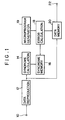
- In a recording/reproducing system for digital data (code train), i.e., in a data transmission system, error detection and correction codes are generally used for correcting an error code generated during the data transmission. Fig.1 is a block diagram showing an example of the circuit arrangement of a conventional error detection and correction circuit. Digital data (code train) is inputted to an
input terminal 10, the digital data having been error-correction coded at the recording (or transmitting) side and passed through a transmission system and may include a transmission error. Adata reproduction circuit 12 causes the input data at theinput terminal 10 to be subjected to demodulation, synchronous separation, ID recognition, and other processes to thereby reproduce each data (code) and output the reproduced data. This reproduced data (code train) is directly written in adata memory 20 in accordance with the recognized ID information, and is also applied to asyndrome calculation circuit 14 for error correction. - In accordance with a known manner, the
syndrome calculation circuit 14 executes a syndrome calculation for each error correction code constructed of a plurality of transmission codes, and sequentially writes a plurality of syndromes for each error correction code into asyndrome memory 16. An error position and errorpattern calculation circuit 18 reads syndromes written in thesyndrome memory 16 and decodes the error correction code. Thecircuit 18 may be constructed of a general arithmetic operation processing circuit, and the operation thereof is controlled by amicroprogram 19. If an error is detected and it is judged that the error is correctable, then the error position and error pattern are calculated, and using the calculated results the data (code) in thedata memory 20 is corrected. If it is judged that the error is not correctable, the corresponding data (code) in thedata memory 20 is maintained unchanged, and a correction flag indicative of a presence of an error is entered in thedata memory 20 while performing other necessary processes. - After the above operations, the error-corrected data (codes) in the
data memory 20 is outputted from anoutput terminal 22. - In the conventional circuit described above, if digital data to be processed is image data, uncorrectable data can be corrected by means of interpolation at a high probability. In such a case, the quality of image is deteriorated by a large probability of error correction rather than by a large probability of uncorrectable error and interpolation. Namely, the degree of deterioration of the image quality is greater upon occurrence of error correction.
- With the advent of a recent transmission path having a large change in transmission error rate such as in the case of a satellite broadcasting whose error rate depends on weather conditions, there has been highly desired to improve the image quality under bad weather as good as possible. One way to solve this is to enhance the error correction capability of the transmission system to the extent that it can support the worst case. However, this solution is not practical because large cast and facilities are required for such an enhanced error correction capability.
- EP-A-0136604 discloses a decoding system capable of high speed decoding using an inner code and an outer code. The decoding system performs a first decoding using the inner code. Using the results of the inner coding a number of decoding modes are decided between on the basis of a statistical processing of the error number flags issued from the first decoder.
- US-A-4541091 describes a code error detection and correction method and apparatus in which a code error rate counter detects the error code rate of an input code train. When the code error counter detects more than a predetermined number of code errors, the code error correction is inhibited.
- SMPTE Journal, Vol. 95, No. 11, November 1986, New York, US, "The SMPTE Type D-1 Digital Television Tape Recorder-Error Control" by J.H. Wilkinson describes a method of error correction using a two level code array in order to enable the correction of very short errors in the inner correction coding, and the correction of a small number of very long sequences of coding in the outer correction coding.
- EP-A-0102782 describes a method of correcting errors in a digital television signal. In the method a parity word is formed from correction units derived from the data words of the television signal.
- It is an object of the present invention to solve the above problems.
- It is another object of the present invention to provide an error detection and correction device capable of obtaining an optimum reproduced code train irrespective of a change in reliability of a transmission line.
- With the above objects in view, according to one aspect of the present invention, there is provided an error detection and correction device, comprising:
- a) input means for inputting a code train including a number of error correction codes each constructed of a plurality of codes;
- b) error correction means for correcting error codes by using an error correction code within the code train; and
- c) selection means for selecting as the operation mode of said error correction means one of a plurality of modes including first and second modes arranged to select said second mode when error information representative of the error code rate of said code train exceeds a predetermined value, and to select said first mode when the error information is smaller than said predetermined value;
- According to a second aspect of the present invention there is provided an error detection and correction method comprising steps of:
- inputting via a transmission path a code train including a number of error correction codes each constructed of a plurality of code,
- correcting error codes by using the error correction code within the code train, and
- selecting as the operation mode of said error correction means one of a plurality of modes including first and second modes, arranged to select said second mode when error information representative of the error code rate of said code train exceeds a predetermined value, and to select said first mode when the error information is smaller than said predetermined value;
- said method being characterized in including the further steps of:
- correcting the error codes in the first mode when the number of the error codes is less than or equal to m and performing no error correction otherwise, and correcting the error codes in the second mode when the number of the error codes is less than or equal to n and performing no error correction otherwise, wherein m and n are different nonzero natural numbers, wherein m is greater than n, and both of the first and second modes use the same error correction code.
- The above and other objects and advantages of the present invention will become apparent from the following detailed description of the preferred embodiments.
-
- Fig. 1 is a block diagram showing an example of the arrangement of a conventional error correction circuit;
- Fig.2 is a block diagram showing an example of the arrangement of an error correction circuit according to an embodiment of this invention;
- Fig.3 is a diagram showing the uncorrectable probability and error correction probability in each error correction mode;
- Fig.4 is a block diagram showing an example of the arrangement of an error correction circuit according to another embodiment of this invention; and
- Fig.5 is a block diagram showing an example of the arrangement of an error correction circuit according to a further embodiment of this invention.
- The embodiments of this invention will be described with reference to the accompanying drawings.
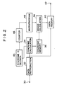
- Fig.2 is a block diagram showing the arrangement of the error correction circuit according to the embodiment of this invention. Similar to the
input terminal 10, digital data (code train) is inputted to aninput terminal 30, the digital data having passed through a transmission path and may include a transmission error. Adata reproduction circuit 32 causes the input data at theinput terminal 30 to be subjected to demodulation, synchronous separation, ID recognition, and other processes to thereby reproduce each data (code) and output the reproduced data. This reproduced data is directly written in adata memory 40 in accordance with the recognized ID information, and is also applied to asyndrome calculation circuit 34 for error correction. In accordance with a known manner, thesyndrome calculation circuit 34 executes a syndrome calculation for each error correction code constructed of a plurality of transmission codes, and sequentially writes a plurality of syndrome for each error correction code into asyndrome memory 36. - The calculation results obtained by the
syndrome calculation circuit 34 are also supplied to a syndrome 0detection circuit 44. Thiscircuit 44 judges whether the plurality of syndromes for each error correction code are all 0 or not. From the output of the syndrome 0decision circuit 44, acounter 46 counts the number of error correction codes whose syndrome are not all 0, i.e., counts during a predetermined time duration the number of error correction codes having an error. The count value of thecounter 46 at the predetermined time duration corresponds to the information representative of the transmission error rate. In accordance with this error rate information, thecounter 46 generates and outputs a mode selection signal for selecting an error correction algorithm to be described later. Asa simplified example of the mode selection signal, it uses one bit information which takes a value 1 for the transmission error rate equal to or larger than a predetermined value, and 0 for the transmission error rate smaller than the predetermined value. - An error position and error
pattern calculation circuit 38 is constructed of a general arithmetic operation processing circuit, and is controlled by amicroprogram generator 48. As will be described later, themicroprogram generator 48 is provided with a plurality of program modules each having a different decoding algorithm. The error position and errorpattern calculation circuit 38 is controlled by a module selected by a mode selection signal supplied from thecounter 46. Specifically, thecircuit 38 executes an error correction suitable for reproducing image data with less image deterioration, by using the optimum decoding algorithm for the current transmission error rate. - A more particular description will be given in the following. It is assumed now that the current error correction code is a two errors correctable code, and that two types of decoding modes for different transmission error rates have been set in the
microprogram generator 48. In the normal mode while the error rate is low, i.e., while each error correction code has one or two error codes, the error position and errorpattern calculation circuit 38 executes an error correction process, and executes not an error correction process but an uncorrectable error process if three or more error codes are generated. The error correction process means to calculate the error position and error pattern, and by using the calculated results, correct the error code in thedata memory 40. The uncorrectable error process means to judge the error as uncorrectable, maintain unchanged the corresponding error correction code in thedata memory 40, enter a correction flag indicative of a presence of an error in the data memory, and perform other necessary processes. - If the transmission error rate becomes bad and the count value of the
counter 46 exceeds the predetermined threshold value, themicroprogram generator 48 selects a program module for a specific mode in accordance with a mode selection signal supplied thereto. For example, an error correction process is executed only if there is one error code in each error correction code, and an uncorrectable error process is executed if there are two error codes or more. - Example of the decoding error rate characteristics for the normal mode and for the specific mode used with a bad error rate are shown in Fig.3. A line 1 indicates the uncorrectable probability during the normal mode, i.e., during a mode for correcting up to two error codes, a
line 2 indicates the error correction probability during the normal mode, a line 3 indicates the uncorrectable probability during the specific mode used with a bad error rate, i.e., during a mode for correcting only one error code, and a line 4 indicates the error correction probability during the specific mode. As compared with the normal mode, during the specific mode, although the uncorrectable probability increases, i.e., becomes bad, the error correction probability becomes small. Accordingly, by using the normal mode while the error rate is small and the specific mode while it is large, the error correction probability can be restricted within an allowable range except a considerably large error rate. - The error position and error
pattern calculation circuit 38 reads syndromes written in thesyndrome memory 36 to execute a decoding process for the error correction code. If all syndromes for the corresponding error correction code are 0, it is judged that there is no error to thereby terminate the processing for that code. On the other hand, all syndromes are not 0, there is an error and if the error is judged as correctable, thecircuit 38 calculates the error position and error pattern, and using the calculated results, the code stored in the data memory is corrected. If the error is judged as uncorrectable, the corresponding code in the data memory is remained unchanged, a flag indicative of a presence of an error is entered in thedata memory 40, and other necessary processes are executed. - For data such as image data which can be effectively corrected even if they are regarded uncorrectable, it is desirable, as described previously, to make small the number of interpolations and make small the number of error corrections from the standpoint of signal quality (image quality). The embodiment therefore allows to reproduce image data with less image quality deterioration.
- In the above embodiment, a code capable of two errors detection and two errors correction has been described by way of example. It is obvious that the present invention is not limited thereto. Also the number of modes which can be set by the
microprogram generator 48 is not limited to two. - As readily appreciated from the foregoing description of this embodiment, use of an additional simple circuit can make small the error probability. If a code capable of effectively executing an interpolation process is used such as in video data, it can be processed with the advantageous effects of making small the quality deterioration of a produced image.
- Fig.4 is a block diagram showing the arrangement of an error detection and correction device according to another embodiment of this invention. Like elements to those shown in Fig.2 are represented by identical reference numerals, and the description therefor is omitted.
- In this embodiment, the present invention is applied to a digital VTR having a transmission path of a magnetic recording and reproducing system. In Fig.4, T represents a magnetic tape, and Ha and Hb represent a rotary magnetic head. The rotary magnetic heads Ha and Hb alternately trace the magnetic tape T and alternately output a reproduced signal. A switch 31 selects the outputs of the heads Ha and Hb, and supplies it as the reproduced data (code train) to a
data reproduction circuit 32. - The VTR of this embodiment has two modes, one being the normal reproduction mode for running the magnetic tape T at the speed same as that during the recording, and the other being the specific reproduction mode for running the magnetic tape T at the speed different from that during the recording. These reproduction modes are selected by an operator from an
operation unit 52. In accordance with an instruction from theoperation unit 52, asystem controller 50 outputs a mode setting signal to control the circuits of the device. Specifically, thesystem controller 50 supplies the mode setting signal to acapstan controller 54 to control a capstan C so that during the normal reproduction mode magnetic tape T is caused to run at the speed same as that during the recording, whereas during the specific reproduction mode, it is caused to run at a preset speed different from that during the recording. The system controller supplies the mode setting signal also to amicroprogram generator 48 which selects a program for the normal mode during the normal reproduction mode, and a program for the specific mode during the specific reproduction mode. - During the normal reproduction mode, an error correction process is executed if there are two or less error codes, and an uncorrectable process is executed if there are three of more error codes. During the specific reproduction mode, an error correction process is executed if there is one error code, and an uncorrectable process if there is three or more error codes.
- In general, during the normal reproduction mode, the tracing loci of the rotary heads Ha and Hb are generally parallel with the recorded helical track and the tracking control is executed. Therefore, there seldom occurs a high error code rate of a reproduced code train from the switch 31. On the other hand, during the specific reproduction mode, the tracing loci of the rotary heads Ha and Hb intersect with the recorded helical track so that the error code rate of a reproduced code train becomes high. In view of this, according to this embodiment, a normal error correction is executed during the normal reproduction mode, and an error correction capability is lowered during the specific reproduction mode to thereby make the error correction probability equal to or lower than a predetermined value.
- The embodiment device shown in Fig.4 has similar advantageous effects to the embodiment shown in Fig. 2. In addition, the embodiment device applied to a reproducing system can make the circuit for switching between the normal mode and specific mode considerably simple, as compared with the embodiment shown in Fig.2.
- Fig.5 is a block diagram showing the arrangement of an error detection and correction device according to a still further embodiment of this invention. Like elements to those shown in Fig.2 are represented by identical reference numerals, and the detailed description therefor is omitted.
- The embodiment shown in Fig.5 assumes to use as the correction coding system a so-called chain coding system which has as the error correction code so-called inner and outer codes.
Reference numeral 35 represents a syndrome calculation circuit for an inner code, 37 a syndrome memory for an inner code, 39 an error calculation circuit for an inner code, 49 a microprogram generator for an inner code. These circuits perform, for an inner code, similar operations to those of thecircuits Reference numeral 55 represents a syndrome calculation circuit for an outer code, 57 a syndrome memory for an outer code, 59 an error calculation circuit for an outer code, and 51 a microprogram generator for an outer code. These circuits perform, for an outer code, similar operations to those of thecircuits - In this embodiment, the
microprogram generator 49 for an inner code is always set at a normal mode. The results calculated by thesyndrome calculation circuit 55 for an outer code are supplied to a syndrome 0 decision circuit lls to decide whether or not all of a plurality of syndromes for each outer code are 0. Acounter 47, similar to thecounter 46 shown in Fig.2, causes themicroprogram generator 51 for an outer code to select a program module which performs an error correction process if there are two or less error codes and performs an uncorrectable process if there are three or more error codes, respectively when the number of outer codes with error is equal to or smaller than a predetermined threshold value during a predetermined time duration. The counter also causes themicroprogram generator 51 for an outer code to select a program module which always performs not an error correction process but an uncorrectable process when the number of outer codes with error exceeds the predetermined threshold value. - With the above circuit arrangement, a sufficient error correction is executed if the error code rate is low, and another error correction process for an outer code is executed if the error code rate is high. Namely, if the error code rate is high, the error correction capability is lowered as a whole to restrict the occurrence of error corrections equal to or lower than a predetermined value, to thereby prevent large deterioration of the reproduced data (code train).
- In the embodiment shown in Fig.5, if the number of outer codes with error during the predetermined time duration exceeds the predetermined threshold value, the
microprogram generator 51 for an outer code selects a program module for executing another process. For instance, advantageous effects can be obtained by selecting a program module which executes an error correction process only when there is one error code and executes an uncorrectable process which there are two or more error codes.
the first mode is a mode in which error correction is performed when the number of the error codes is less than or equal to m and in which no error correction is performed otherwise and the second mode is a mode in which error correction is performed when the number of the error codes is less than or equal to n and in which no error correction is performed otherwise, wherein m and n are different nonzero natural numbers, wherein m is greater than n, and both of the first and second modes use the same error correction code.
Claims (13)
- An error detection and correction device, comprising:a) input means (32) for inputting a code train including a number of error correction codes each constructed of a plurality of codes;b) error correction means (38, 59) for correcting error codes by using an error correction code within the code train; andc) selection means (48, 51) for selecting as the operation mode of said error correction means (38, 59) one of a plurality of modes including first and second modes, arranged to select said second mode when error information representative of the error code rate of said code train exceeds a predetermined value, and to select said first mode when the error information is smaller than said predetermined value;characterized in that
the first mode is a mode in which error correction is performed when the number of the error codes is less than or equal to m and in which no error correction is performed otherwise and the second mode is a mode in which error correction is performed when the number of the error codes is less than or equal to n and in which no error correction is performed otherwise, wherein m and n are different nonzero natural numbers, wherein m is greater than n, and both of the first and second modes use the same error correction code. - A device according to claim 1, further comprising detection means (44, 46, 45, 47) for detecting error information representative of the error code rate of said code train, wherein said selection means (48) is arranged to select the first mode and the second mode according to an output of said detection means (44, 46, 45, 47).
- A device according to claim 1 or 2, wherein said error correction code is of the type that two error codes for each error correction code can be corrected, and said error correction means (38) is arranged to execute an error correction process in said first mode if there are two or less error codes for each error correction code, and to execute an error correction process in said second mode only if there is one error code for each error correction code.
- A device according to claim 1 or 2, wherein said error correction code comprises first and second error correction codes.
- A device according to claim 4, wherein said first error correction code is a code which is coded and decoded at the more outer part of the transmission path of the code train than said second error correction code.
- A device according to claim 2, wherein said detection means (44, 46, 45, 47) includes a detection circuit (44, 45) which is arranged to detect the presence or absence of an error code in each error correction code in accordance with a plurality of syndromes for each error correction code.
- A device according to claim 6, wherein said detection circuit (44, 45) is arranged to detect whether all said plurality of syndromes are 0.
- A device according to claim 6, wherein said detection means (44, 46, 45, 47) includes a counter circuit (46, 47) arranged to count the number of error detection codes with an error code during a predetermined time duration by using a detection output from said detection circuit (44, 45).
- A device according to claim 1, wherein said input means includes a reproducion head (Ha, Hb) for reproducing said code train from a number of helical tracks formed on a tape recording medium (T), said device further comprising:generation means (50) for generating mode setting information associated with error code rate of said code train;feeding means (54, C) for feeding said tape recording medium (T), said feeding means (54, C) being arranged to select as the feeding speed of said tape recording medium (T) one of a plurality of speeds including first and second speeds, in accordance with the mode setting information from said generation means (50), wherein when said tape recording medium (T) is fed at said first speed, said reproduction head (Ha, Hb) is arranged to trace said tape recording medium (T) substantially in parallel with the longitudinal direction of said helical track, and when said tape recording medium (T) is fed at said second speed, said reproduction head (Ha, Hb) is arranged to trace said tape recording medium (T) in the direction to intersect said longitudinal direction of said helical track.
- A device according to claim 9, wherein said selection means (48, 51) is arranged to select said first mode when said feeding means feeds said tape recording medium (T) at said first speed, and to select said second mode when said feeding means feeds said tape recording medium (T) at said second speed.
- A device according to claim 1, wherein said input means (32) includes a reproducion head (Ha, Hb) for reproducing said code train from a tape recording medium (T).
- A device according to claim 11, further comprising:
setting means for setting a reproduction mode of said reproducion head, wherein said selection means selects the first and second modes of said error correction means according to an output of said setting means. - An error detection and correction method comprising steps of:inputting via a transmission path a code train including a number of error correction codes each constructed of a plurality of code,correcting error codes by using the error correction code within the code train, andselecting as the operation mode of said error correction means one of a plurality of modes including first and second modes, arranged to select said second mode when error information representative of the error code rate of said code train exceeds a predetermined value, and to select said first mode when the error information is smaller than said predetermined value;said method being characterized in including the further steps of:correcting the error codes in the first mode when the number of the error codes is less than or equal to m and performing no error correction otherwise, and correcting the error codes in the second mode when the number of the error codes is less than or equal to n and performing no error correction otherwise, wherein m and n are different nonzero natural numbers, wherein m is greater than n, and both of the first and second modes use the same error correction code.
Applications Claiming Priority (2)
| Application Number | Priority Date | Filing Date | Title |
|---|---|---|---|
| JP01144530A JP3137119B2 (en) | 1989-06-07 | 1989-06-07 | Error correction device |
| JP144530/89 | 1989-06-07 |
Publications (3)
| Publication Number | Publication Date |
|---|---|
| EP0402115A2 EP0402115A2 (en) | 1990-12-12 |
| EP0402115A3 EP0402115A3 (en) | 1991-06-26 |
| EP0402115B1 true EP0402115B1 (en) | 1997-08-20 |
Family
ID=15364464
Family Applications (1)
| Application Number | Title | Priority Date | Filing Date |
|---|---|---|---|
| EP90306151A Expired - Lifetime EP0402115B1 (en) | 1989-06-07 | 1990-06-06 | Device and method for error detection and correction |
Country Status (4)
| Country | Link |
|---|---|
| US (2) | US5687182A (en) |
| EP (1) | EP0402115B1 (en) |
| JP (1) | JP3137119B2 (en) |
| DE (1) | DE69031294T2 (en) |
Cited By (5)
| Publication number | Priority date | Publication date | Assignee | Title |
|---|---|---|---|---|
| EP0571096A2 (en) * | 1992-05-18 | 1993-11-24 | Canon Kabushiki Kaisha | Data processing apparatus |
| EP0730795A1 (en) * | 1993-11-22 | 1996-09-11 | Thomson Consumer Electronics, Inc. | Satellite receiver code rate switching apparatus |
| US5784356A (en) * | 1995-10-27 | 1998-07-21 | Kabushiki Kaisha Toshiba | Optical disk reproducing apparatus equipped with variable gain amplifier capable of adjusting amplitude of reproduction signal |
| WO2000030108A2 (en) * | 1998-11-16 | 2000-05-25 | Ecrix Corporation | A method of reacquiring clock synchronization on a non-tracking helical scan tape device |
| US6564343B1 (en) | 1999-02-19 | 2003-05-13 | Fujitsu Limited | Bit interleave circuit and bit deinterleave circuit |
Families Citing this family (31)
| Publication number | Priority date | Publication date | Assignee | Title |
|---|---|---|---|---|
| JPH03166826A (en) * | 1989-11-25 | 1991-07-18 | Victor Co Of Japan Ltd | Error detecting and correcting device |
| JPH06104773A (en) * | 1992-07-20 | 1994-04-15 | Internatl Business Mach Corp <Ibm> | Circuit and method for finding of programmable requential ket-type solution for finding of key-type solution of linear algebraic code |
| KR19990071860A (en) * | 1996-09-30 | 1999-09-27 | 이데이 노부유끼 | Playback device, error correction device, and error correction method |
| US5974580A (en) * | 1997-07-23 | 1999-10-26 | Cirrus Logic, Inc. | Concurrent row/column syndrome generator for a product code |
| JPH1166762A (en) * | 1997-08-08 | 1999-03-09 | Alps Electric Co Ltd | Floppy disk system |
| US6457156B1 (en) * | 1998-01-29 | 2002-09-24 | Adaptec, Inc. | Error correction method |
| US6272659B1 (en) * | 1998-05-18 | 2001-08-07 | Cirrus Logic, Inc. | Error correction code processor employing adjustable correction power for miscorrection minimization |
| JP2000251419A (en) * | 1999-02-26 | 2000-09-14 | Sony Corp | Read control device, reproducing device, recording device, and method therefor |
| US6405340B1 (en) * | 1999-07-02 | 2002-06-11 | Ericsson Inc. | Flexible method of error protection in communications systems |
| JP3450756B2 (en) * | 1999-09-08 | 2003-09-29 | 松下電器産業株式会社 | Error correction method and error correction device |
| US6662335B1 (en) * | 2000-01-25 | 2003-12-09 | Mediatek Inc. | Method and apparatus for accessing DVD data |
| JP3352659B2 (en) * | 2000-03-27 | 2002-12-03 | 松下電器産業株式会社 | Decoding device and decoding method |
| KR20020065788A (en) * | 2001-02-07 | 2002-08-14 | 삼성전자 주식회사 | Reed-Solomon decoder for processing data with m or 2m bits and method thereof |
| US7290184B2 (en) * | 2001-08-23 | 2007-10-30 | Seagate Technology Llc | Emulation system for evaluating digital data channel configurations |
| EP1569348A1 (en) * | 2004-02-13 | 2005-08-31 | Alcatel | Iterative multidimensional decoding |
| US7707588B2 (en) * | 2004-03-02 | 2010-04-27 | Avicode, Inc. | Software application action monitoring |
| US20070260963A1 (en) * | 2006-04-21 | 2007-11-08 | Kuo-Lung Chien | Error correction system and related method thereof |
| US20070260960A1 (en) * | 2006-04-21 | 2007-11-08 | Kuo-Lung Chien | Error correction system and related method thereof |
| US20070260961A1 (en) * | 2006-04-21 | 2007-11-08 | Kuo-Lung Chien | Error correction system and related method thereof |
| BRPI0811117A2 (en) * | 2007-05-16 | 2014-12-23 | Thomson Licensing | APPARATUS AND METHOD FOR ENCODING AND DECODING SIGNS |
| US20090070655A1 (en) * | 2007-09-11 | 2009-03-12 | Silicon Motion, Inc. | Method for Generating an ECC Code for a Memory Device |
| JP2011501926A (en) | 2007-10-15 | 2011-01-13 | トムソン ライセンシング | Apparatus and method for encoding and decoding signals |
| WO2009051693A2 (en) | 2007-10-15 | 2009-04-23 | Thomson Licensing | Preamble for a digital television system |
| US8051332B2 (en) * | 2008-07-15 | 2011-11-01 | Avicode Inc. | Exposing application performance counters for .NET applications through code instrumentation |
| US9104794B2 (en) * | 2008-07-15 | 2015-08-11 | Microsoft Technology Licensing, Llc | Automatic incremental application dependency discovery through code instrumentation |
| US8296620B2 (en) * | 2008-08-26 | 2012-10-23 | Seagate Technology Llc | Data devices including multiple error correction codes and methods of utilizing |
| US9323609B2 (en) * | 2013-11-15 | 2016-04-26 | Intel Corporation | Data storage and variable length error correction information |
| US9983972B2 (en) | 2015-06-01 | 2018-05-29 | Cisco Technology, Inc. | Predictive in-field memory repair scheme |
| US10140180B1 (en) * | 2016-11-04 | 2018-11-27 | Seagate Technology Llc | Segment-based outer code recovery |
| US10177791B1 (en) * | 2016-11-08 | 2019-01-08 | Seagate Technology Llc | Syndrome update and maintenance |
| US10831596B2 (en) * | 2018-01-22 | 2020-11-10 | Micron Technology, Inc. | Enhanced error correcting code capability using variable logical to physical associations of a data block |
Citations (1)
| Publication number | Priority date | Publication date | Assignee | Title |
|---|---|---|---|---|
| EP0136604A2 (en) * | 1983-09-14 | 1985-04-10 | Matsushita Electric Industrial Co., Ltd. | Decoding method and system. |
Family Cites Families (18)
| Publication number | Priority date | Publication date | Assignee | Title |
|---|---|---|---|---|
| US3078443A (en) * | 1959-01-22 | 1963-02-19 | Alan C Rose | Compound error correction system |
| US3638182A (en) * | 1970-01-02 | 1972-01-25 | Bell Telephone Labor Inc | Random and burst error-correcting arrangement with guard space error correction |
| US4404673A (en) * | 1981-02-09 | 1983-09-13 | National Semiconductor Corporation | Error correcting network |
| NL8200207A (en) * | 1982-01-21 | 1983-08-16 | Philips Nv | METHOD OF ERROR CORRECTION FOR TRANSFERRING BLOCK DATA BITS, AN APPARATUS FOR CARRYING OUT SUCH A METHOD, A DECODOR FOR USE BY SUCH A METHOD, AND AN APPARATUS CONTAINING SUCH A COVER. |
| US4541091A (en) * | 1982-06-11 | 1985-09-10 | Hitachi, Ltd. | Code error detection and correction method and apparatus |
| GB2126760B (en) * | 1982-08-20 | 1985-08-29 | Sony Corp | Error correction of digital television signals |
| JPS59200547A (en) * | 1983-04-26 | 1984-11-13 | Nec Corp | Monitoring system for circuit quality |
| JPS59228440A (en) * | 1983-06-09 | 1984-12-21 | Fujitsu Ltd | Data transmission system |
| AU597576B2 (en) * | 1985-05-21 | 1990-06-07 | Sony Corporation | Apparatus for decoding error correcting code |
| EP0235782B1 (en) * | 1986-03-04 | 1992-01-22 | Sony Corporation | Apparatus for reproducing a digital signal |
| DE3752367T2 (en) * | 1986-09-30 | 2004-02-19 | Canon K.K. | Error correction unit |
| US4953019A (en) * | 1987-11-27 | 1990-08-28 | Canon Kabushiki Kaisha | Image signal encoding apparatus |
| US5070503A (en) * | 1988-03-09 | 1991-12-03 | Canon Kabushiki Kaisha | Digital information transmitting and receiving system |
| US4866719A (en) * | 1988-03-21 | 1989-09-12 | Sony Corporation | System and method for performing error correction on still frame audio tape format video signals |
| JP2638091B2 (en) * | 1988-06-24 | 1997-08-06 | ソニー株式会社 | Data transmission method |
| US5068855A (en) * | 1988-07-18 | 1991-11-26 | Canon Kabushiki Kaisha | Error correcting method and apparatus |
| US4979174A (en) * | 1988-12-29 | 1990-12-18 | At&T Bell Laboratories | Error correction and detection apparatus and method |
| US5212695A (en) * | 1989-04-28 | 1993-05-18 | Canon Kabushiki Kaisha | Error check or erro correction code coding device |
-
1989
- 1989-06-07 JP JP01144530A patent/JP3137119B2/en not_active Expired - Lifetime
-
1990
- 1990-06-06 DE DE69031294T patent/DE69031294T2/en not_active Expired - Fee Related
- 1990-06-06 EP EP90306151A patent/EP0402115B1/en not_active Expired - Lifetime
-
1994
- 1994-12-14 US US08/355,986 patent/US5687182A/en not_active Expired - Lifetime
-
1997
- 1997-07-17 US US08/895,819 patent/US5996109A/en not_active Expired - Fee Related
Patent Citations (1)
| Publication number | Priority date | Publication date | Assignee | Title |
|---|---|---|---|---|
| EP0136604A2 (en) * | 1983-09-14 | 1985-04-10 | Matsushita Electric Industrial Co., Ltd. | Decoding method and system. |
Non-Patent Citations (1)
| Title |
|---|
| & JP-A- 59 200547 * |
Cited By (7)
| Publication number | Priority date | Publication date | Assignee | Title |
|---|---|---|---|---|
| EP0571096A2 (en) * | 1992-05-18 | 1993-11-24 | Canon Kabushiki Kaisha | Data processing apparatus |
| US5436917A (en) * | 1992-05-18 | 1995-07-25 | Canon Kabushiki Kaisha | Data processing apparatus having error detection/correction codes |
| EP0730795A1 (en) * | 1993-11-22 | 1996-09-11 | Thomson Consumer Electronics, Inc. | Satellite receiver code rate switching apparatus |
| EP0730795B1 (en) * | 1993-11-22 | 2003-02-19 | Thomson Consumer Electronics, Inc. | Satellite receiver code rate switching apparatus |
| US5784356A (en) * | 1995-10-27 | 1998-07-21 | Kabushiki Kaisha Toshiba | Optical disk reproducing apparatus equipped with variable gain amplifier capable of adjusting amplitude of reproduction signal |
| WO2000030108A2 (en) * | 1998-11-16 | 2000-05-25 | Ecrix Corporation | A method of reacquiring clock synchronization on a non-tracking helical scan tape device |
| US6564343B1 (en) | 1999-02-19 | 2003-05-13 | Fujitsu Limited | Bit interleave circuit and bit deinterleave circuit |
Also Published As
| Publication number | Publication date |
|---|---|
| US5996109A (en) | 1999-11-30 |
| JP3137119B2 (en) | 2001-02-19 |
| DE69031294D1 (en) | 1997-09-25 |
| EP0402115A3 (en) | 1991-06-26 |
| US5687182A (en) | 1997-11-11 |
| JPH0310422A (en) | 1991-01-18 |
| DE69031294T2 (en) | 1997-12-18 |
| EP0402115A2 (en) | 1990-12-12 |
Similar Documents
| Publication | Publication Date | Title |
|---|---|---|
| EP0402115B1 (en) | Device and method for error detection and correction | |
| EP0571096B1 (en) | Data processing apparatus | |
| US4764927A (en) | Code error correcting method | |
| US5247523A (en) | Code error correction apparatus | |
| US7055082B2 (en) | Information recording and reproducing apparatus | |
| US4972416A (en) | Error detection and correction method | |
| JPH0520105A (en) | Error correction device of degital data | |
| JP2558994B2 (en) | Digital image signal error correction method and error correction device | |
| US6522831B2 (en) | Reproducing apparatus | |
| JPH0634313B2 (en) | Error correction method | |
| JP2574740B2 (en) | PCM signal reproduction device | |
| US6047398A (en) | Reproducing method, reproducing apparatus and recording and reproducing apparatus using the same reproducing method, and recording medium having the same method recorded therein | |
| KR100223821B1 (en) | The circuit and method for error correction in a dvd | |
| JP3210002B2 (en) | Error correction device | |
| JP3277062B2 (en) | Error correction code decoding device | |
| KR0160603B1 (en) | Error correction apparatus | |
| JP2751415B2 (en) | Error detection and correction circuit | |
| JPH07264077A (en) | Error detection and correction circuit | |
| JPH0628343B2 (en) | Product code decoding method | |
| JP3302183B2 (en) | Tracking control device | |
| JPH05328290A (en) | Data reproduction processing circuit | |
| JPH0831114A (en) | Digital information recording/reproducing device | |
| JPH06124550A (en) | Digital data recording device | |
| JPS63187471A (en) | Digital data recorder | |
| JPS6366097B2 (en) |
Legal Events
| Date | Code | Title | Description |
|---|---|---|---|
| PUAI | Public reference made under article 153(3) epc to a published international application that has entered the european phase |
Free format text: ORIGINAL CODE: 0009012 |
|
| AK | Designated contracting states |
Kind code of ref document: A2 Designated state(s): DE ES FR GB IT NL |
|
| 17P | Request for examination filed |
Effective date: 19901231 |
|
| PUAL | Search report despatched |
Free format text: ORIGINAL CODE: 0009013 |
|
| AK | Designated contracting states |
Kind code of ref document: A3 Designated state(s): DE ES FR GB IT NL |
|
| 17Q | First examination report despatched |
Effective date: 19930927 |
|
| GRAG | Despatch of communication of intention to grant |
Free format text: ORIGINAL CODE: EPIDOS AGRA |
|
| GRAH | Despatch of communication of intention to grant a patent |
Free format text: ORIGINAL CODE: EPIDOS IGRA |
|
| GRAH | Despatch of communication of intention to grant a patent |
Free format text: ORIGINAL CODE: EPIDOS IGRA |
|
| GRAA | (expected) grant |
Free format text: ORIGINAL CODE: 0009210 |
|
| AK | Designated contracting states |
Kind code of ref document: B1 Designated state(s): DE ES FR GB IT NL |
|
| PG25 | Lapsed in a contracting state [announced via postgrant information from national office to epo] |
Ref country code: IT Free format text: LAPSE BECAUSE OF FAILURE TO SUBMIT A TRANSLATION OF THE DESCRIPTION OR TO PAY THE FEE WITHIN THE PRE;WARNING: LAPSES OF ITALIAN PATENTS WITH EFFECTIVE DATE BEFORE 2007 MAY HAVE OCCURRED AT ANY TIME BEFORE 2007. THE CORRECT EFFECTIVE DATE MAY BE DIFFERENT FROM THE ONE RECORDED.SCRIBED TIME-LIMIT Effective date: 19970820 Ref country code: ES Free format text: THE PATENT HAS BEEN ANNULLED BY A DECISION OF A NATIONAL AUTHORITY Effective date: 19970820 |
|
| REF | Corresponds to: |
Ref document number: 69031294 Country of ref document: DE Date of ref document: 19970925 |
|
| ET | Fr: translation filed | ||
| PLBE | No opposition filed within time limit |
Free format text: ORIGINAL CODE: 0009261 |
|
| STAA | Information on the status of an ep patent application or granted ep patent |
Free format text: STATUS: NO OPPOSITION FILED WITHIN TIME LIMIT |
|
| 26N | No opposition filed | ||
| REG | Reference to a national code |
Ref country code: GB Ref legal event code: IF02 |
|
| PGFP | Annual fee paid to national office [announced via postgrant information from national office to epo] |
Ref country code: DE Payment date: 20080630 Year of fee payment: 19 Ref country code: NL Payment date: 20080618 Year of fee payment: 19 |
|
| PGFP | Annual fee paid to national office [announced via postgrant information from national office to epo] |
Ref country code: FR Payment date: 20080625 Year of fee payment: 19 |
|
| PGFP | Annual fee paid to national office [announced via postgrant information from national office to epo] |
Ref country code: GB Payment date: 20080627 Year of fee payment: 19 |
|
| GBPC | Gb: european patent ceased through non-payment of renewal fee |
Effective date: 20090606 |
|
| NLV4 | Nl: lapsed or anulled due to non-payment of the annual fee |
Effective date: 20100101 |
|
| REG | Reference to a national code |
Ref country code: FR Ref legal event code: ST Effective date: 20100226 |
|
| PG25 | Lapsed in a contracting state [announced via postgrant information from national office to epo] |
Ref country code: FR Free format text: LAPSE BECAUSE OF NON-PAYMENT OF DUE FEES Effective date: 20090630 |
|
| PG25 | Lapsed in a contracting state [announced via postgrant information from national office to epo] |
Ref country code: GB Free format text: LAPSE BECAUSE OF NON-PAYMENT OF DUE FEES Effective date: 20090606 |
|
| PG25 | Lapsed in a contracting state [announced via postgrant information from national office to epo] |
Ref country code: DE Free format text: LAPSE BECAUSE OF NON-PAYMENT OF DUE FEES Effective date: 20100101 |
|
| PG25 | Lapsed in a contracting state [announced via postgrant information from national office to epo] |
Ref country code: NL Free format text: LAPSE BECAUSE OF NON-PAYMENT OF DUE FEES Effective date: 20100101 |