EP0406021B1 - Disk recording and reproducing device - Google Patents
Disk recording and reproducing device Download PDFInfo
- Publication number
- EP0406021B1 EP0406021B1 EP90307184A EP90307184A EP0406021B1 EP 0406021 B1 EP0406021 B1 EP 0406021B1 EP 90307184 A EP90307184 A EP 90307184A EP 90307184 A EP90307184 A EP 90307184A EP 0406021 B1 EP0406021 B1 EP 0406021B1
- Authority
- EP
- European Patent Office
- Prior art keywords
- information
- recording
- recorded
- area
- write
- Prior art date
- Legal status (The legal status is an assumption and is not a legal conclusion. Google has not performed a legal analysis and makes no representation as to the accuracy of the status listed.)
- Expired - Lifetime
Links
- 238000012545 processing Methods 0.000 claims description 25
- 230000000452 restraining effect Effects 0.000 claims description 5
- 230000004044 response Effects 0.000 claims description 3
- 230000000694 effects Effects 0.000 claims 1
- 238000013139 quantization Methods 0.000 claims 1
- 230000003287 optical effect Effects 0.000 description 26
- 230000033458 reproduction Effects 0.000 description 25
- 238000010586 diagram Methods 0.000 description 17
- 238000000034 method Methods 0.000 description 13
- 230000006870 function Effects 0.000 description 11
- 230000002950 deficient Effects 0.000 description 3
- 238000012423 maintenance Methods 0.000 description 3
- 230000007246 mechanism Effects 0.000 description 3
- 238000012937 correction Methods 0.000 description 2
- 230000007547 defect Effects 0.000 description 2
- 238000001514 detection method Methods 0.000 description 2
- 238000005562 fading Methods 0.000 description 2
- 230000005415 magnetization Effects 0.000 description 2
- 238000012544 monitoring process Methods 0.000 description 2
- 230000005374 Kerr effect Effects 0.000 description 1
- 230000008859 change Effects 0.000 description 1
- 238000007796 conventional method Methods 0.000 description 1
- 238000013016 damping Methods 0.000 description 1
- 230000007423 decrease Effects 0.000 description 1
- 239000006185 dispersion Substances 0.000 description 1
- 230000030279 gene silencing Effects 0.000 description 1
- 230000012447 hatching Effects 0.000 description 1
- 230000007257 malfunction Effects 0.000 description 1
- 230000010287 polarization Effects 0.000 description 1
- 230000008569 process Effects 0.000 description 1
- 230000007704 transition Effects 0.000 description 1
Images


Classifications
-
- G—PHYSICS
- G11—INFORMATION STORAGE
- G11B—INFORMATION STORAGE BASED ON RELATIVE MOVEMENT BETWEEN RECORD CARRIER AND TRANSDUCER
- G11B7/00—Recording or reproducing by optical means, e.g. recording using a thermal beam of optical radiation by modifying optical properties or the physical structure, reproducing using an optical beam at lower power by sensing optical properties; Record carriers therefor
-
- G—PHYSICS
- G11—INFORMATION STORAGE
- G11B—INFORMATION STORAGE BASED ON RELATIVE MOVEMENT BETWEEN RECORD CARRIER AND TRANSDUCER
- G11B20/00—Signal processing not specific to the method of recording or reproducing; Circuits therefor
- G11B20/00086—Circuits for prevention of unauthorised reproduction or copying, e.g. piracy
- G11B20/00137—Circuits for prevention of unauthorised reproduction or copying, e.g. piracy involving measures which result in a restriction to contents recorded on or reproduced from a record carrier to authorised users
-
- G—PHYSICS
- G11—INFORMATION STORAGE
- G11B—INFORMATION STORAGE BASED ON RELATIVE MOVEMENT BETWEEN RECORD CARRIER AND TRANSDUCER
- G11B11/00—Recording on or reproducing from the same record carrier wherein for these two operations the methods are covered by different main groups of groups G11B3/00 - G11B7/00 or by different subgroups of group G11B9/00; Record carriers therefor
- G11B11/10—Recording on or reproducing from the same record carrier wherein for these two operations the methods are covered by different main groups of groups G11B3/00 - G11B7/00 or by different subgroups of group G11B9/00; Record carriers therefor using recording by magnetic means or other means for magnetisation or demagnetisation of a record carrier, e.g. light induced spin magnetisation; Demagnetisation by thermal or stress means in the presence or not of an orienting magnetic field
- G11B11/105—Recording on or reproducing from the same record carrier wherein for these two operations the methods are covered by different main groups of groups G11B3/00 - G11B7/00 or by different subgroups of group G11B9/00; Record carriers therefor using recording by magnetic means or other means for magnetisation or demagnetisation of a record carrier, e.g. light induced spin magnetisation; Demagnetisation by thermal or stress means in the presence or not of an orienting magnetic field using a beam of light or a magnetic field for recording by change of magnetisation and a beam of light for reproducing, i.e. magneto-optical, e.g. light-induced thermomagnetic recording, spin magnetisation recording, Kerr or Faraday effect reproducing
- G11B11/10502—Recording on or reproducing from the same record carrier wherein for these two operations the methods are covered by different main groups of groups G11B3/00 - G11B7/00 or by different subgroups of group G11B9/00; Record carriers therefor using recording by magnetic means or other means for magnetisation or demagnetisation of a record carrier, e.g. light induced spin magnetisation; Demagnetisation by thermal or stress means in the presence or not of an orienting magnetic field using a beam of light or a magnetic field for recording by change of magnetisation and a beam of light for reproducing, i.e. magneto-optical, e.g. light-induced thermomagnetic recording, spin magnetisation recording, Kerr or Faraday effect reproducing characterised by the transducing operation to be executed
-
- G—PHYSICS
- G11—INFORMATION STORAGE
- G11B—INFORMATION STORAGE BASED ON RELATIVE MOVEMENT BETWEEN RECORD CARRIER AND TRANSDUCER
- G11B11/00—Recording on or reproducing from the same record carrier wherein for these two operations the methods are covered by different main groups of groups G11B3/00 - G11B7/00 or by different subgroups of group G11B9/00; Record carriers therefor
- G11B11/10—Recording on or reproducing from the same record carrier wherein for these two operations the methods are covered by different main groups of groups G11B3/00 - G11B7/00 or by different subgroups of group G11B9/00; Record carriers therefor using recording by magnetic means or other means for magnetisation or demagnetisation of a record carrier, e.g. light induced spin magnetisation; Demagnetisation by thermal or stress means in the presence or not of an orienting magnetic field
- G11B11/105—Recording on or reproducing from the same record carrier wherein for these two operations the methods are covered by different main groups of groups G11B3/00 - G11B7/00 or by different subgroups of group G11B9/00; Record carriers therefor using recording by magnetic means or other means for magnetisation or demagnetisation of a record carrier, e.g. light induced spin magnetisation; Demagnetisation by thermal or stress means in the presence or not of an orienting magnetic field using a beam of light or a magnetic field for recording by change of magnetisation and a beam of light for reproducing, i.e. magneto-optical, e.g. light-induced thermomagnetic recording, spin magnetisation recording, Kerr or Faraday effect reproducing
- G11B11/1055—Disposition or mounting of transducers relative to record carriers
- G11B11/10556—Disposition or mounting of transducers relative to record carriers with provision for moving or switching or masking the transducers in or out of their operative position
-
- G—PHYSICS
- G11—INFORMATION STORAGE
- G11B—INFORMATION STORAGE BASED ON RELATIVE MOVEMENT BETWEEN RECORD CARRIER AND TRANSDUCER
- G11B11/00—Recording on or reproducing from the same record carrier wherein for these two operations the methods are covered by different main groups of groups G11B3/00 - G11B7/00 or by different subgroups of group G11B9/00; Record carriers therefor
- G11B11/10—Recording on or reproducing from the same record carrier wherein for these two operations the methods are covered by different main groups of groups G11B3/00 - G11B7/00 or by different subgroups of group G11B9/00; Record carriers therefor using recording by magnetic means or other means for magnetisation or demagnetisation of a record carrier, e.g. light induced spin magnetisation; Demagnetisation by thermal or stress means in the presence or not of an orienting magnetic field
- G11B11/105—Recording on or reproducing from the same record carrier wherein for these two operations the methods are covered by different main groups of groups G11B3/00 - G11B7/00 or by different subgroups of group G11B9/00; Record carriers therefor using recording by magnetic means or other means for magnetisation or demagnetisation of a record carrier, e.g. light induced spin magnetisation; Demagnetisation by thermal or stress means in the presence or not of an orienting magnetic field using a beam of light or a magnetic field for recording by change of magnetisation and a beam of light for reproducing, i.e. magneto-optical, e.g. light-induced thermomagnetic recording, spin magnetisation recording, Kerr or Faraday effect reproducing
- G11B11/10595—Control of operating function
-
- G—PHYSICS
- G11—INFORMATION STORAGE
- G11B—INFORMATION STORAGE BASED ON RELATIVE MOVEMENT BETWEEN RECORD CARRIER AND TRANSDUCER
- G11B19/00—Driving, starting, stopping record carriers not specifically of filamentary or web form, or of supports therefor; Control thereof; Control of operating function ; Driving both disc and head
- G11B19/02—Control of operating function, e.g. switching from recording to reproducing
- G11B19/04—Arrangements for preventing, inhibiting, or warning against double recording on the same blank or against other recording or reproducing malfunctions
-
- G—PHYSICS
- G11—INFORMATION STORAGE
- G11B—INFORMATION STORAGE BASED ON RELATIVE MOVEMENT BETWEEN RECORD CARRIER AND TRANSDUCER
- G11B20/00—Signal processing not specific to the method of recording or reproducing; Circuits therefor
- G11B20/00086—Circuits for prevention of unauthorised reproduction or copying, e.g. piracy
- G11B20/00137—Circuits for prevention of unauthorised reproduction or copying, e.g. piracy involving measures which result in a restriction to contents recorded on or reproduced from a record carrier to authorised users
- G11B20/00152—Circuits for prevention of unauthorised reproduction or copying, e.g. piracy involving measures which result in a restriction to contents recorded on or reproduced from a record carrier to authorised users involving a password
-
- G—PHYSICS
- G11—INFORMATION STORAGE
- G11B—INFORMATION STORAGE BASED ON RELATIVE MOVEMENT BETWEEN RECORD CARRIER AND TRANSDUCER
- G11B20/00—Signal processing not specific to the method of recording or reproducing; Circuits therefor
- G11B20/10—Digital recording or reproducing
-
- G—PHYSICS
- G11—INFORMATION STORAGE
- G11B—INFORMATION STORAGE BASED ON RELATIVE MOVEMENT BETWEEN RECORD CARRIER AND TRANSDUCER
- G11B20/00—Signal processing not specific to the method of recording or reproducing; Circuits therefor
- G11B20/10—Digital recording or reproducing
- G11B20/10527—Audio or video recording; Data buffering arrangements
-
- G—PHYSICS
- G11—INFORMATION STORAGE
- G11B—INFORMATION STORAGE BASED ON RELATIVE MOVEMENT BETWEEN RECORD CARRIER AND TRANSDUCER
- G11B20/00—Signal processing not specific to the method of recording or reproducing; Circuits therefor
- G11B20/10—Digital recording or reproducing
- G11B20/12—Formatting, e.g. arrangement of data block or words on the record carriers
- G11B20/1217—Formatting, e.g. arrangement of data block or words on the record carriers on discs
- G11B20/1251—Formatting, e.g. arrangement of data block or words on the record carriers on discs for continuous data, e.g. digitised analog information signals, pulse code modulated [PCM] data
-
- G—PHYSICS
- G11—INFORMATION STORAGE
- G11B—INFORMATION STORAGE BASED ON RELATIVE MOVEMENT BETWEEN RECORD CARRIER AND TRANSDUCER
- G11B20/00—Signal processing not specific to the method of recording or reproducing; Circuits therefor
- G11B20/10—Digital recording or reproducing
- G11B20/18—Error detection or correction; Testing, e.g. of drop-outs
- G11B20/1883—Methods for assignment of alternate areas for defective areas
-
- G—PHYSICS
- G11—INFORMATION STORAGE
- G11B—INFORMATION STORAGE BASED ON RELATIVE MOVEMENT BETWEEN RECORD CARRIER AND TRANSDUCER
- G11B27/00—Editing; Indexing; Addressing; Timing or synchronising; Monitoring; Measuring tape travel
- G11B27/02—Editing, e.g. varying the order of information signals recorded on, or reproduced from, record carriers
- G11B27/031—Electronic editing of digitised analogue information signals, e.g. audio or video signals
- G11B27/034—Electronic editing of digitised analogue information signals, e.g. audio or video signals on discs
-
- G—PHYSICS
- G11—INFORMATION STORAGE
- G11B—INFORMATION STORAGE BASED ON RELATIVE MOVEMENT BETWEEN RECORD CARRIER AND TRANSDUCER
- G11B27/00—Editing; Indexing; Addressing; Timing or synchronising; Monitoring; Measuring tape travel
- G11B27/02—Editing, e.g. varying the order of information signals recorded on, or reproduced from, record carriers
- G11B27/031—Electronic editing of digitised analogue information signals, e.g. audio or video signals
- G11B27/036—Insert-editing
-
- G—PHYSICS
- G11—INFORMATION STORAGE
- G11B—INFORMATION STORAGE BASED ON RELATIVE MOVEMENT BETWEEN RECORD CARRIER AND TRANSDUCER
- G11B27/00—Editing; Indexing; Addressing; Timing or synchronising; Monitoring; Measuring tape travel
- G11B27/02—Editing, e.g. varying the order of information signals recorded on, or reproduced from, record carriers
- G11B27/031—Electronic editing of digitised analogue information signals, e.g. audio or video signals
- G11B27/038—Cross-faders therefor
-
- G—PHYSICS
- G11—INFORMATION STORAGE
- G11B—INFORMATION STORAGE BASED ON RELATIVE MOVEMENT BETWEEN RECORD CARRIER AND TRANSDUCER
- G11B27/00—Editing; Indexing; Addressing; Timing or synchronising; Monitoring; Measuring tape travel
- G11B27/10—Indexing; Addressing; Timing or synchronising; Measuring tape travel
- G11B27/102—Programmed access in sequence to addressed parts of tracks of operating record carriers
- G11B27/105—Programmed access in sequence to addressed parts of tracks of operating record carriers of operating discs
-
- G—PHYSICS
- G11—INFORMATION STORAGE
- G11B—INFORMATION STORAGE BASED ON RELATIVE MOVEMENT BETWEEN RECORD CARRIER AND TRANSDUCER
- G11B27/00—Editing; Indexing; Addressing; Timing or synchronising; Monitoring; Measuring tape travel
- G11B27/10—Indexing; Addressing; Timing or synchronising; Measuring tape travel
- G11B27/11—Indexing; Addressing; Timing or synchronising; Measuring tape travel by using information not detectable on the record carrier
-
- G—PHYSICS
- G11—INFORMATION STORAGE
- G11B—INFORMATION STORAGE BASED ON RELATIVE MOVEMENT BETWEEN RECORD CARRIER AND TRANSDUCER
- G11B27/00—Editing; Indexing; Addressing; Timing or synchronising; Monitoring; Measuring tape travel
- G11B27/10—Indexing; Addressing; Timing or synchronising; Measuring tape travel
- G11B27/19—Indexing; Addressing; Timing or synchronising; Measuring tape travel by using information detectable on the record carrier
- G11B27/28—Indexing; Addressing; Timing or synchronising; Measuring tape travel by using information detectable on the record carrier by using information signals recorded by the same method as the main recording
- G11B27/30—Indexing; Addressing; Timing or synchronising; Measuring tape travel by using information detectable on the record carrier by using information signals recorded by the same method as the main recording on the same track as the main recording
- G11B27/3027—Indexing; Addressing; Timing or synchronising; Measuring tape travel by using information detectable on the record carrier by using information signals recorded by the same method as the main recording on the same track as the main recording used signal is digitally coded
-
- G—PHYSICS
- G11—INFORMATION STORAGE
- G11B—INFORMATION STORAGE BASED ON RELATIVE MOVEMENT BETWEEN RECORD CARRIER AND TRANSDUCER
- G11B27/00—Editing; Indexing; Addressing; Timing or synchronising; Monitoring; Measuring tape travel
- G11B27/10—Indexing; Addressing; Timing or synchronising; Measuring tape travel
- G11B27/19—Indexing; Addressing; Timing or synchronising; Measuring tape travel by using information detectable on the record carrier
- G11B27/28—Indexing; Addressing; Timing or synchronising; Measuring tape travel by using information detectable on the record carrier by using information signals recorded by the same method as the main recording
- G11B27/32—Indexing; Addressing; Timing or synchronising; Measuring tape travel by using information detectable on the record carrier by using information signals recorded by the same method as the main recording on separate auxiliary tracks of the same or an auxiliary record carrier
- G11B27/327—Table of contents
- G11B27/329—Table of contents on a disc [VTOC]
-
- G—PHYSICS
- G11—INFORMATION STORAGE
- G11B—INFORMATION STORAGE BASED ON RELATIVE MOVEMENT BETWEEN RECORD CARRIER AND TRANSDUCER
- G11B27/00—Editing; Indexing; Addressing; Timing or synchronising; Monitoring; Measuring tape travel
- G11B27/10—Indexing; Addressing; Timing or synchronising; Measuring tape travel
- G11B27/34—Indicating arrangements
-
- G—PHYSICS
- G11—INFORMATION STORAGE
- G11B—INFORMATION STORAGE BASED ON RELATIVE MOVEMENT BETWEEN RECORD CARRIER AND TRANSDUCER
- G11B27/00—Editing; Indexing; Addressing; Timing or synchronising; Monitoring; Measuring tape travel
- G11B27/36—Monitoring, i.e. supervising the progress of recording or reproducing
-
- G—PHYSICS
- G11—INFORMATION STORAGE
- G11B—INFORMATION STORAGE BASED ON RELATIVE MOVEMENT BETWEEN RECORD CARRIER AND TRANSDUCER
- G11B7/00—Recording or reproducing by optical means, e.g. recording using a thermal beam of optical radiation by modifying optical properties or the physical structure, reproducing using an optical beam at lower power by sensing optical properties; Record carriers therefor
- G11B7/002—Recording, reproducing or erasing systems characterised by the shape or form of the carrier
- G11B7/0037—Recording, reproducing or erasing systems characterised by the shape or form of the carrier with discs
-
- G—PHYSICS
- G11—INFORMATION STORAGE
- G11B—INFORMATION STORAGE BASED ON RELATIVE MOVEMENT BETWEEN RECORD CARRIER AND TRANSDUCER
- G11B2220/00—Record carriers by type
- G11B2220/20—Disc-shaped record carriers
-
- G—PHYSICS
- G11—INFORMATION STORAGE
- G11B—INFORMATION STORAGE BASED ON RELATIVE MOVEMENT BETWEEN RECORD CARRIER AND TRANSDUCER
- G11B2220/00—Record carriers by type
- G11B2220/20—Disc-shaped record carriers
- G11B2220/21—Disc-shaped record carriers characterised in that the disc is of read-only, rewritable, or recordable type
- G11B2220/215—Recordable discs
- G11B2220/216—Rewritable discs
-
- G—PHYSICS
- G11—INFORMATION STORAGE
- G11B—INFORMATION STORAGE BASED ON RELATIVE MOVEMENT BETWEEN RECORD CARRIER AND TRANSDUCER
- G11B2220/00—Record carriers by type
- G11B2220/20—Disc-shaped record carriers
- G11B2220/25—Disc-shaped record carriers characterised in that the disc is based on a specific recording technology
- G11B2220/2525—Magneto-optical [MO] discs
-
- G—PHYSICS
- G11—INFORMATION STORAGE
- G11B—INFORMATION STORAGE BASED ON RELATIVE MOVEMENT BETWEEN RECORD CARRIER AND TRANSDUCER
- G11B2220/00—Record carriers by type
- G11B2220/20—Disc-shaped record carriers
- G11B2220/25—Disc-shaped record carriers characterised in that the disc is based on a specific recording technology
- G11B2220/2537—Optical discs
- G11B2220/2545—CDs
-
- G—PHYSICS
- G11—INFORMATION STORAGE
- G11B—INFORMATION STORAGE BASED ON RELATIVE MOVEMENT BETWEEN RECORD CARRIER AND TRANSDUCER
- G11B2220/00—Record carriers by type
- G11B2220/60—Solid state media
- G11B2220/65—Solid state media wherein solid state memory is used for storing indexing information or metadata
Definitions
- the present invention relates to a disk recording and reproducing device for recording as well as reproducing information, for example, music information or the like on and from a writable disk having absolute addresses.
- CD compact disks
- CD's are used only for reproduction, and for those used for music programs, a plurality of music programs are successively recorded on the disk, and at the innermost track, what we call a lead-in area thereof, there is created a so-called TOC (Table Of Content) area wherein recording start positions and the like with respect to each music program are recorded.
- TOC Table Of Content
- the disk recording and reproducing device since those CD's are used only for reproduction, as a new method, it has been desired to develop a disk recording and reproducing device whereby the user can freely record music programs or the like on a recording medium.
- the recording medium it is suggested to apply magneto-optical disks or the like functioning as a re-writable recording medium.
- the disk recording and reproducing device is preferably designed to have an interchangeability so that it can also reproduce conventional CD's.
- the absolute addresses indicating the recording start position and recording end position thereof are successively recorded in the TOC area while corresponding those absolute addresses to the program numbers, and in the reproductions thereafter the absolute addresses recorded therein are of great use.
- the capacity of the TOC area it is suggested to give a capacity requiring, for example, several tens of second in reproduction, however, in the case where the disk recording and reproducing device is designed to reproduce information in all the TOC area when the disk is placed therein, reproducing time for all the capacity of the TOC area is required even if actual additional information recorded therein is very little compared with the capacity of the TOC area, and therefore a problem arises in that waiting time required to reach a stand-by state is very long.
- the aforementioned disk recording and reproducing device for example, in recording music programs recorded on another recording medium as a music source, it is possible for the user himself to instruct to start a recording operation through operation keys by choosing a right timing while listening to the music program coming from the music source.
- the recording operation is sometimes performed from a position H located away past the recording start position F of the former music program.
- a recording area of the former music program that is, a range shown by F to G, and it is possible that a recording of a new music program is started from H within the range.
- the user has to determine a reproducing level and a recording level at the disk recording and reproducing device as a reproducing device and at the external device as a recording device while examining level meters or the like.
- One of the objects of the present invention is to solve the above problem; however, by the use of the invention, when write protection is applied to each music program, and then a new music program is recorded in a non-write-protection range, there arises a case where the capacity of the non-write-protection range (range where write protection is not applied) is smaller than the capacity required to record the new music program therein. Therefore, in reproducing from the disk wherein such recordings are made, the performance of the newly recorded music program is finished halfway, and simultaneously with the finishing, the performance of the music program recorded in a write protection range is started. Consequently, a drawback is presented in that the listener feels displeased because of having a missing part at the end of the music program.
- the present invention aims at providing a disk recording and reproducing device having full functions.
- JP-A-1-179 275 published on 17th July 1989, discloses an optical disk recording device in which a signal is faded out during recording at the end of an available recording area. The timing of the fade-out is determined according to an absolute time recorded on the disk.
- JP-A-1-143 081 discloses a magnetic disk device in which secret data is prevented from being read using a pass word signal of low frequency recorded with the data signal.
- EP-A-0 292 917 already describes an apparatus for recording and/or reproducing an optical disk with a TOC area, in which the TOC is completed when a further recording is made.
- WO-A-88/07254 already describes a disk recording/reproducing apparatus, where in a kind of a TOC an erasure inhibit flag for each recorded unit can be recorded.
- EP-A-0 378 449 which is only relevant under Art.54(3), already describes to store additional data in the TOC, as e.g. silence damping and fade-in/fade-out (cf. p.15 1.17).
- the present invention provides the recording and reproducing device defined by claim 1.
- the sound in reproducing music information recorded in a non-write-protection range, gradually decreases before the end of the music information, and therefore, since it is completed without giving the impression of a missing part at the end, the listener does not experience an unpleasant feeling.
- the present invention provides the recording and reproducing device defined by claim 5.
- the maintenance of secrecy is possible with respect to desired programs of recorded information.
- write protection is automatically applied to the program of information having read protection if an entered pass word does not agree with the pass word already recorded, it is preventable for another person who does not know the pass word to rewrite on an area of the disk containing recorded information and having read protection, by misunderstanding that there is no information recorded in the area because the protected recorded information is not reproduced. Thus, erasing important information is avoidable.
- Figs. 1 to 5 show one example which is useful for understanding the present invention.
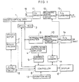
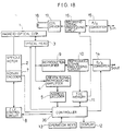
- Fig. 1 is a schematic block diagram showing a disk recording and reproducing device.
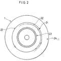
- Fig. 2 is a schematic plan view of a magneto-optical disk.
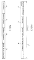
- Fig. 3 is an explanatory diagram showing a format of data.
- Fig. 4 is an explanatory diagram showing a format of absolute addresses.
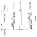
- Fig. 5 is an explanatory diagram showing recording conditions of an information recording area.
- Figs. 11 and 12 show another example which is useful for understanding the present invention.
- Fig. 11 is a schematic block diagram showing a disk recording and reproducing device.
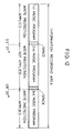
- Fig. 12 is an explanatory diagram showing a condition of write protection applied to the first to third music programs.
- Figs. 13 and 14 show an embodiment of the present invention.
- Fig. 13 is a schematic block diagram showing a disk recording and reproducing device.
- Fig. 14 is an explanatory diagram showing relationship and the like between an input signal to a fader circuit and an output signal from the fader circuit.
- Figs. 15 to 18 show another embodiment of the present invention.
- Fig. 15 is a schematic block diagram showing a disk recording and reproducing device.
- Fig. 16 is an explanatory diagram showing a condition of read protection applied to the first to third music programs.
- Fig. 17 is an explanatory diagram showing conditions of write protection and read protection applied to the first to third music programs.
- Fig. 18 is a schematic block diagram showing a disk recording and reproducing device.
- Figs. 19 to 22 are omitted in this specification.
- Figs. 23 to 26 are diagrams showing the prior art.
- Fig. 23 is an explanatory diagram showing recording conditions of an information recording area.
- Fig. 24 is an explanatory diagram showing the position of an absolute address for recording start and the position of track-jumps, located on a track.
- Fig. 25 is an explanatory diagram showing the position of the absolute address for the recording start and the position of the track-jumps, according to the time-axis.
- Fig. 26 is an explanatory diagram showing the position from which the re-recording is started in Fig. 25.
- a magneto-optical disk is employed as a re-writable disk, and the device is designed to record and reproduce music information or the like by the use of data formats standardized in CD's, and to perform reproduction of the conventional CD's as well.
- a magneto-optical disk 1 there are predeterminately provided a track 21 in a spiral shape, and absolute addresses 22 in at least recording areas where recording and reproducing operations are performed.
- the recording areas include an information recording area 24 wherein information of music programs or the like are recorded by the user, and a TOC area 23 located at the innermost track of the disk 1, wherein additional information with respect to each music program recorded in the information recording area 24 is recorded.
- information a of one frame comprises a frame synchronizing signal b , a data field d including data of 24 bytes for a music program or the like and an additional parity of 8 bytes for error detection and correction, and a sub-code c for recording a program number, time information and the like for each data field d .
- Pieces of the above-mentioned information a are successively recorded in the information recording area 24 and the TOC area 23.
- the sub-code c since the sub-code c isn't particularly necessary, its contents can be predeterminately set.
- each of the absolute addresses 22 comprises a preamble e for reproduction synchronization, an address mark f for indicating the leading part of the respective absolute addresses 22, an address number g for showing each address successively incrementing one by one from the innermost track of the magneto-optical disk 1(to be concrete, the absolute time in one second) and an error detection code h for detecting errors in recognizing the address numbers g , and those absolute addresses are predeterminately formed in a pit-like shape so that they are reproduced once every one second in a given linear velocity.
- Fig. 1 shows one example of a disk recording and reproducing device which performs recording and reproducing operations on and from a magneto-optical disk 1.
- the magneto-optical disk 1 is rotatively driven by a spindle motor 2, and above the one side of the magneto-optical disk 1, is disposed an optical head 3 for applying a light beam onto the magneto-optical disk 1 so as to record or reproduce information thereon or therefrom.
- an uneven signal component reproduced from the absolute addresses 22 is amplified by an uneven signal reproducing amplifier 4.
- the amplified uneven signal component is sent to an address decoder 5 where the value of the absolute address 22 is recognized, and then is sent to a controller 6 which executes control operation on the whole mechanisms of the disk recording and reproducing device.
- a controller 6 which executes control operation on the whole mechanisms of the disk recording and reproducing device.
- the pulses from the rotary encoder 7 are entered to a CLV control circuit 8 and to a controller 6.
- the CLV control circuit 8 is designed to control rotation speed of the spindle motor 2 so that the linear velocity of the optical head 3 to the magneto-optical disk 1 can be kept constant according to the aforementioned pulses and to positional information of the optical head 3 released from the controller 6.
- a reproduction amplifier 9 connected to the optical head 3
- a magneto-optical signal component corresponding to each music program reproduced by the optical head 3 is amplified, and sent to a reproduced signal processing circuit 10.
- the reproduced signal processing circuit 10 processes the reproduced data of the music program or the like having a data format shown in Fig. 3 by selecting necessary data and sorting them, and performs error correction processing, if necessary.
- TOC memory 11 In the TOC memory 11, are successively stored pieces of information specified by the user (specified through a group of operation keys 13 which will be described later). To the controller 6, is connected a display 12 which displays the additional information and the like stored in the TOC memory 11. To the controller 6, is also connected the group of operation keys 13 whereby the user executes various instructions.
- A/D converter 14 By a D/A converter 14 connected to the reproduced signal processing circuit 10, digital data sequences from the reproduced signal processing circuit 10 are converted to analog signals, and are released to the external device as analog signals S out .
- analog signals S in for a music program entered from the external device are converted to digital signals by an A/D converter 15, and are sent to a recording signal processing circuit 16.
- the recording signal processing circuit 16 permits the music program from the A/D converter 15, or additional information or the like from the TOC memory 11 to be converted to signals having a data format respectively shown in Fig. 3, and produces recording signals.
- a coil driver 17 is designed to drive a magnetic coil 18 according to the recording signals from the recording signal processing circuit 16, and to permit the magnetic coil 18 to apply an external magnetic field to the magneto-optical disk 1 corresponding to the recording signals.
- the controller 6 controls an optical head transportation system (not shown in Figs.) to shift the optical head 3 to a position corresponding to the TOC area 23, and on the other hand gives positional information corresponding to the position to the CLV control circuit 8.
- the CLV control circuit 8 finds the number of rotation required to obtain a predetermined linear velocity, and also finds a pulse frequency reference value for the rotary encoder 7 corresponding to the number of the rotation.
- the CLV control circuit 8 then rotatively drives the magneto-optical disk 1 at the predetermined linear velocity by controlling the actual output pulse frequency of the rotary encoder 7 to have the same value with the pulse frequency reference value.
- absolute addresses 22 are released from the optical head 3 as reproduced signals, and after being amplified by the uneven signal reproducing amplifier 4 and being recognized their absolute addresses 22 by the address decoder 5, the absolute addresses 22 as those reproduced signals are entered to the controller 6.
- the positional information does not necessarily conform to the actual position because of dispersions of machine accuracy and the like, and therefore it is difficult to obtain an accurate predetermined linear velocity.
- Analog signals S in for a music program entered from the external device are converted into digital signals by the A/D converter 15, and by their format being converted to the aforementioned predetermined format through the recording signal processing circuit 16, recording signals are produced.
- the magnetic coil 18 is driven by the coil driver 17, and a magnetic field in response to the recording data is applied onto the magneto-optical disk 1.
- Magnetic coercive force lowers in a local part where a temperature rise has occurred by the application of the light beam.
- the direction of magnetization is reversed by the magnetic field applied by the magnetic coil 18, thereby permitting the information to be recorded.
- this method is generally referred to as magnetic field modulation method whereby rewriting on an area where recordings have already been made is possible by overwriting thereon.
- additional information including at least a program number of each music program recorded in the information recording area 24 and a recording start position and a recording end position of each music program according to the absolute addresses 22, is recorded by the optical head 3 and the magnetic coil 18 in the same manner as was aforementioned in recording in the information recording area 24. Furthermore, at the recording end position of the additional information located in the last part of the TOC area 23 is recorded a predetermined end mark.
- the magneto-optical disk 1 when the magneto-optical disk 1 is placed in the disk recording and reproducing device, as aforementioned, the contents of the TOC area 23 are read by the optical head 3 and stored in the TOC memory 11.
- the end mark "EE" recorded in the position where the program number of the third music program is supposed to be recorded by overwriting thereon, is recorded the program number "03" of the third music program, and further the recording start position as well as the recording end position of the newly recorded third music program M3 is recorded. Then, in order to show that the additional information with respect to the third music program M3 is the last additional information recorded within the TOC area 23, the end mark "EE" is recorded in the position where the program number of the fourth music program is supposed to be recorded.
- the arrangement allows time required to record the additional information to be shortened. Further, in the arrangement, since the end mark "EE" is recorded in the furthest rear end of additional information, reproduction of the TOC area 23 can be completed upon reproducing the end mark "EE", and therefore reproducing time for TOC area 23 can be shortened by eliminating such inefficiency as to reproduce all the TOC area 23.
- the same magneto-optical disk 1 is used as a re-writable disk, and the device is designed to record and reproduce information by the use of data formats standardized in conventional CD's.
- the disk recording and reproducing device of the present example has the same arrangement as that shown in
- a controller 27 is used therein instead of the controller 6 in Fig. 1.
- the controller 27 not only controls the whole mechanisms of the disk recording and reproducing device, but also functions as control means, which will be described later. Moreover, a display 12 is connected to the controller 27, and the display 12 displays thereon a program number, time information and write protection information with respect to each of the music programs, according to the contents of a TOC memory 11 (memory means).
- a TOC memory 11 memory means
- the controller 27 also functions as control means for controlling to restrain the device from writing in a write protection range when an instruction is given by the user so as to write in the write protection range in his information recording instruction.
- control means to restrain recording operation such a method is suggested, wherein while driving of an optical head 3 (application of light beam required for recording) is stopped, the control operation, which has proceeded to a routine for recording information information, is returned to a routine for waiting for key input in the controller 27.
- the recorded contents of the TOC area 23 include, for example, the program number, the recording start position and recording end position and the like recorded therein according to the absolute addresses 22, with respect to each of the music programs or the like recorded in the information recording area 24 (see Fig. 2).
- the controller 27 When the magneto-optical disk 1 is placed on a spindle motor 2, the controller 27 on the one hand shifts the optical head 3 to the TOC area 23, and on the other hand rotates the magneto-optical disk 1 at a predetermined linear velocity to reproduce the contents of the TOC area 23.
- the TOC area 23 When there are some pieces of information recorded in the TOC area 23, it permits the TOC memory to store those pieces of information therein.
- the recording start position and recording end position of each corresponding program number correspond to the time information given by the absolute addresses 22, and are read from the TOC area 23 and stored in the TOC memory 11.
- the controller 27 permits the display 12 to display thereon the above contents of the TOC memory 11.
- the user can recognize the contents of the music programs or the like recorded in the disk 1 by the above-mentioned contents displayed, and if he wants to listen to, for example, the second music program, he gives an instruction to do so through operation keys 13.
- the controller 27 makes the optical head 3 access to an absolute address position showing (03'57") in Table 8, thereby permitting the selection of the music program.
- the controller 27 stores the write protection information in the TOC memory 11.
- the write protection may be also given to a space between music programs, disposed after the end of the music program to which write protection is given.
- the contents of the TOC memory 11 are recorded in the TOC area 23 as additional information, for example, when the magneto-optical disk 1 is removed from the spindle motor 2, or when the user specifies the necessity of the recording through the operation keys 13. Accordingly, even if the magneto-optical disk 1 is removed from the disk recording and reproducing device, the write protection information is maintained in the magneto-optical disk 1.
- the write protection information is read from the TOC area 23 and stored in the TOC memory 11, and recording control is performed according to the contents. Further, the write protection information once entered is effective unless it is updated, and therefore the write protection is executed with respect to the first and third music programs every time recording is made on the magneto-optical disk 1.
- the optical head 3 and a magnetic coil 18 function as recording means for recording in the TOC area 23 the contents stored in the TOC memory 11 as additional information.
- a fader circuit 28 before an A/D converter 15 in addition to the arrangement shown in Fig. 11.
- a controller 27 is connected to the fader circuit 28.
- Music programs (music information) as analog signals are entered to the fader circuit 28, where fade-out processing is applied to the music programs according to the instruction of the controller 27, and the processed music programs are entered to the A/D converter 15.
- the controller 27 also give instructions to the fader circuit 28 about the timing when to apply the fade-out processing according to the information of the TOC memory 11 (information read from the TOC area 23, as shown in Fig. 2).
- the time corresponding to the non-write-protection area (writable areas) is from (03'57") to (08'20"), that is to say, there is a writable range of 4 min. 23 sec.
- a music program requiring more than 4 min. 23 sec. is recorded in the writable range, since the recording of the music program is finished halfway, a fade-out operation is applied thereto according to predetermined timing. For example, as shown in Fig.
- the fade-out operation is applied to the music program at the time (08'13")t 1 ) which is seven seconds before the write protection start time (08'20") by a method such as monitoring the elapsed time of the music program during its recording operation.
- the fade-out operation is preset so as to become soundless at the time three seconds before the end within the seven seconds, and during the three seconds, a soundless condition is maintained, thereby forming a three second space between the newly recorded second music program and the third music program.
- the fade-out processing is applied to music programs entered as analog signals; however, when music programs are entered as digital signals, the fade-out processing can be applied to the digital signals as they are.
- the disk recording and reproducing device comprises the operation keys which are operable by the user, the memory means for storing therein write protection information to each of desired pieces of information entered through the operation keys, the recording means for recording in the TOC area the contents stored in the memory means as additional information, the control means for restraining writing operation in a write protection range and a fader circuit for applying the fade-out processing to the information before the end of a non-write-protection range when information is recorded in the non-write-protection range and, at least, the capacity of the information to be recorded is greater than that of the non-write-protection range.
- the recorded information is a music program and it is reproduced, the sound becomes gradually fading out before the end of the music program, and therefore, since the music program is completed without giving the impression of having a missing part at the end, it is avoidable to give unpleasant feeling to the listener.
- Figs. 2, 15 and 16 the same magneto-optical disk 1 as before is used as a re-writable disk, as shown in Fig. 2, and the device is designed to record and reproduce information by the use of data formats standardized in conventional CD's. Further, those of members having the same functions as before are indicated by the same reference numerals and the description thereof is omitted.
- a disk recording and reproducing device of the present embodiment basically has the same arrangement as that shown in Fig. 1 except that a controller 29 is used therein instead of the controller 6 in Fig. 1.
- the controller 29 not only controls the whole mechanisms of the disk recording and reproducing device, but also functions as control means, which will be described later.
- a TOC memory (memory means) 11 stores those of the signals corresponding to the contents of the TOC area 23, as shown in Fig. 2, among signals processed by a reproduced signal processing circuit 10, and on the other hand, has an arrangement such that it can store information specified by the user through operation keys 13, for example, the recording start position, pass word and the like of each music program.
- a display 12 is connected to the controller 29, and the display 12 displays the music program number, time information and also the read protection information and the like of each music program, according to the contents of the TOC memory 11. Further, to the controller 29 there is connected the group of operation keys 13, whereby the user can give various instructions such as those for the aforementioned pass word.
- the controller 29 also functions as control means for restraining the reproduction of recorded music programs which have corresponding read protection information, when an input pass word entered through the operation keys 13 is compared with a recorded pass word which is read from the TOC area 23 of the magneto-optical disk 1 shown in Fig. 2 and stored in the TOC memory 11 and if those pass words do not agree with each other.
- the recorded contents of the TOC area 23 include, for example, the program number, the recording start position and recording end position and the like recorded therein according to the absolute addresses 22, with respect to each of the music programs recorded in the information recording region 24 (see Fig. 2), and also include the aforementioned pass word.
- the recording start position and recording end position of each corresponding program number correspond to the time information given by the absolute addresses 22, and are read from the TOC area 23 and stored in the TOC memory 11.
- the controller 29 displays the above contents of the TOC memory 11 on the display 12.
- the controller 29 permits the TOC memory 11 to store the read protection information therein. Further, the user enters a pass word to release the read protection information through the operation keys 13 (for example, when the operation keys are ten keys for selecting music programs, numbers such as "0123" are entered as the pass word). Upon receiving the instruction, the controller 29 permits the TOC memory 11 to store the pass word information therein.
- the read protection information is maintained in the magneto-optical disk 1 even if the magneto-optical disk 1 is removed from the disk recording and reproducing device.
- the read protection information is read from the TOC area 23 and stored in the TOC memory 11, and therefore the read protection information once entered is effective unless it is updated. Accordingly, the read protection is executed with respect to the first and third music programs every time recording is made on the magneto-optical disk 1.
- the controller 29 upon receiving an instruction by the user to reproduce a music program having read protection, the controller 29 on the one hand displays a message on the display 12 to show that the music program has read protection, and on the other hand requests the user to enter the pass word.
- the input pass word is compared with the pass word already recorded. As a result of the comparison, if those pass words do not agree with each other, the controller 29 restrains the reproduction of the music program. On the other hand, if both of the pass words agree with each other, the controller 29 permits the normal reproduction.
- a disk recording and reproducing device of this embodiment has the same arrangement as that shown in Fig. 15 except that a controller 35 is installed therein instead of the controller 29 as the aforementioned control means in Fig. 15.
- the controller 35 after comparing an input pass word entered through operation keys 13 and a pass word already recorded and upon receiving no agreement between those pass words, on the one hand inhibits the reproduction of a recorded music program having the corresponding read protection information, and on the other hand controls the device to automatically apply write protection to the recorded music program having the corresponding read protection, as shown in Fig. 17.
- a controller 36 is installed instead of the controller 35 (Fig. 15) as the aforementioned control means.
- the controller 36 after comparing an input pass word entered through operation keys 13 and the aforementioned pass word already recorded and upon receiving no agreement between those pass words, controls the device to lower the quality of reproduced signals in reproducing recorded information having the corresponding read protection information.
- the controller 36 is connected to a D/A converter 14, and in reproducing information having the corresponding read protection, the controller 36 controls the D/A converter 14 to fix the low order bit of the quantizing data.
- the arrangement causes the resolution of the quantizing data to lower in the D/A converter 14, resulting in the lowering of the reproduced signal quality due to the lowering of the resolution.
- variable filter which is controlled by the controller 36. More specifically, in reproducing information having the corresponding read protection, the controller 36 controls the variable filter to narrow a frequency band for reproducing the music program so as to lower the quality of the reproduced signals.
- the quality of the reproduced signals may be lowered by giving an intermittent reproducing operation by the use of the timer installed in the controller 36 so as not to perform a successive reproducing operation, or by giving noise to the reproduced signals.
- the disk recording and reproducing device comprises the operation keys which are operable by the user, the memory means for storing therein read protection information to desired pieces of recorded information and a pass word to release the read protection information, entered through the operation keys, recording means for recording in the TOC area the contents stored in the memory means as additional information, and the control means for restraining the reproduction of the recorded information having the corresponding read protection information, after comparing the input pass word entered through the operation keys and the pass word already recorded, when no agreement between those pass words is obtained.
- the application of another control means is proposed, which after comparing the input pass word entered through the operation keys and the pass word already recorded, when no agreement between those pass words is obtained, controls the device on the one hand to restrain the reproduction of recorded information having the corresponding read protection information, and on the other hand to apply write protection to the range of the recorded information having the corresponding read protection information. Then, the demand for the maintenance of secrecy to desired pieces of recorded information can be met, and it is preventable to erase recorded information having the corresponding read protection, or to rewrite on a range containing recorded information and having read protection applied thereto. Thus, erasing important information is avoidable.
- the application of another control means is proposed, which after comparing the input pass word entered through the operation keys and the pass word already recorded, when no agreement between those pass words is obtained, controls the device to lower the quality of reproduced signals in reproducing recorded information having the corresponding read protection information.
- the absolute addresses 22 are formed on the magneto-optical disk 1 in the shape of pits, instead of the arrangement, the absolute addresses 22 can be recorded by modulating frequencies of the absolute addresses 22, and by wobbling the track in response to the values obtained from the modulated frequencies.
- magneto-optical disk as an example of a re-writable disk; however, re-writable disks of other types such as optical disks of phase transition type may be used.
- music programs are taken up as an example of information to be recorded; however, information of other types, for example, such as data for computers or the like may be recorded on the re-writable disk.
Description
- The present invention relates to a disk recording and reproducing device for recording as well as reproducing information, for example, music information or the like on and from a writable disk having absolute addresses.
- Conventionally, there are known compact disks (hereinafter called CD) as a disc shaped recording medium wherein pieces of information such as music programs are recorded by converting them into digital signals.
- These CD's are used only for reproduction, and for those used for music programs, a plurality of music programs are successively recorded on the disk, and at the innermost track, what we call a lead-in area thereof, there is created a so-called TOC (Table Of Content) area wherein recording start positions and the like with respect to each music program are recorded.
- When a CD is placed into a reproducing device for reproduction, information recorded in the TOC area is first reproduced, and then by the information, the number of music programs, recording start time (position) and the like of each program, recorded in the CD placed therein, are recognized, and in the reproducing operations thereafter, an access to any music program is performed in short time by using the information recorded in the TOC area.
- In the meantime, since those CD's are used only for reproduction, as a new method, it has been desired to develop a disk recording and reproducing device whereby the user can freely record music programs or the like on a recording medium. In that case, as the recording medium, it is suggested to apply magneto-optical disks or the like functioning as a re-writable recording medium. Moreover, the disk recording and reproducing device is preferably designed to have an interchangeability so that it can also reproduce conventional CD's.
- As to a recording method in the above arrangement, in order to perform CLV (Constant Linear Velocity) control to the disk, which is executed in the conventional CD's, it is suggested that grooves wobbling according to values of absolute addresses or pits indicating absolute addresses are formed on the disk when it was fabricated, and that, in recording information thereon, accesses to unrecorded parts and the CLV control are performed by using the above absolute addresses, and the same signal formats as those in the conventional CD's are employed.
- Furthermore, in the above re-writable disk, at the time when a recording operation for each music program has been finished, the absolute addresses indicating the recording start position and recording end position thereof are successively recorded in the TOC area while corresponding those absolute addresses to the program numbers, and in the reproductions thereafter the absolute addresses recorded therein are of great use.
- In that case, when a piece of information recorded in an information recording area is rewritten, it is necessary to replace the contents of the TOC area according to the change.
- For example, as shown by (a) in Fig. 23, when music programs from the first program M1 to fourth program M4 are recorded in the information recording area, as shown in Table 1, the program number and the recording start position as well as recording end position for each of the music programs M1 to M4 are recorded as additional information.
Table 1 Program No. Recording Start Position Recording End Position 01 (00'00") (08'37") 02 (08'40") (23'12") 03 (23'16") (39'41") 04 (39'48") (55'30") - Next, as shown by (b) in Fig. 23, in the case where another music program M2′ is newly recorded in an area wherein the second program M2 has already been recorded, if the latter half of the second program M2 remaining after the recording end position of the M2′ is considered to be unnecessary information, it is only necessary to rewrite additional information with respect to the second program in the contents of the TOC area, as shown in Table 2.
Table 2 Program No. Recording Start Position Recording End Position 01 (00'00") (08'37") 02 (08'40") (14'56") 03 (23'16") (39'41") 04 (39'48") (55'30") - However, as shown by (c) in Fig. 23, in the case where another music program M2' is recorded in the area wherein the second program M2 has been recorded, when M2' is longer than the former second program M2, the former third program M3 is partially erased. In that case, if the remaining part of the former third program M3 is considered to be unnecessary information, the contents of the TOC area are replaced as shown in Table 3. More specifically, on the one hand, additional information with respect to the second program is rewritten, and on the other hand, the program number is changed and the former fourth program is moved up to be the third program. Accordingly, in that case, in order to rewrite the information in the TOC area, at least, pieces of information shown by the program numbers "02" and "03" in Table 1 should be rewritten into pieces of information shown by the program numbers "02" and "03" in Table 3, and a piece of information shown by "04" in Table 1 should be erased. When this method is adapted to a case where, for example, there are program numbers from "01" to "30", it requires a lot of time to rewrite the information recorded in the TOC area.
Table 3 Program No. Recording Start Position Recording End Position 01 (00'00") (08'37") 02 (08'40") (32'09") 03 (39'48") (55'30") - Moreover, as to the capacity of the TOC area, it is suggested to give a capacity requiring, for example, several tens of second in reproduction, however, in the case where the disk recording and reproducing device is designed to reproduce information in all the TOC area when the disk is placed therein, reproducing time for all the capacity of the TOC area is required even if actual additional information recorded therein is very little compared with the capacity of the TOC area, and therefore a problem arises in that waiting time required to reach a stand-by state is very long.
- Furthermore, in the aforementioned disk recording and reproducing device, for example, in recording music programs recorded on another recording medium as a music source, it is possible for the user himself to instruct to start a recording operation through operation keys by choosing a right timing while listening to the music program coming from the music source.
- However, in the recording operations for such music programs, the leading part of the music program is sometimes not recorded due to wrong timing in starting the recording operation, and the user suspends the operation halfway when he notices the wrong timing, and then he resumes the recording operation. In that case, it is suggested that, in order to start a recording to be resumed from a position conforming to the start position of the former music program (the music program having been failed in recordings), an absolute address indicating the start position is predeterminately stored, and that, in resuming the recording operation, the recording is operated after returning to the position indicated by the absolute address.
- More concretely, as shown in Fig. 24, assuming that the recording of the music program having been failed in recording is started from a position shown by F in the figure on a
track 59 formed in a spiral state (the recorded part is shown by hatching in the figure), in resuming the recording operation, after accessing an optical head to a position indicated by an absolute address F' of the recording start position predeterminately stored, it is kept in a stand-by state while being permitted to make a track-jump to the inner track every rotation of the disk. In this case, assuming that the track-jump is made from a position G to a position G' in the figure, the route of a light spot is expressed by a loop shown in an alternate long and short dash line in the figure. Therefore, as shown in Fig. 25, signals contained within the section traced back by one rotation are repeatedly reproduced. - However, if the user operates the operation keys at his will during the aforementioned stand-by state, as shown in Fig. 26, the recording operation is sometimes performed from a position H located away past the recording start position F of the former music program. In other words, within the section tracked by one rotation during the aforementioned stand-by state, there is contained a recording area of the former music program, that is, a range shown by F to G, and it is possible that a recording of a new music program is started from H within the range.
- In the case above-mentioned, there remains the former music program located in the section F to H. As a result, in reproduction, the leading part of the former music program is reproduced, although it might be a short period of time, thereby presenting a problem in that the quality of the music program is affected.
- In the meantime, when there are scratches or the like on a magneto-optical disk caused when it was fabricated or due to ill usage by the user, malfunction might arise in recording or reproducing music information or the like thereon or therefrom. Especially in the case of recording successive information of music or the like, even a defect in a part of the disk might cause interruption of the recording from the point on, and might also cause damage on the information already stored in the other areas. Further, in the case of re-writable disks such as magneto-optical disks, the above problems might occur every time a rewriting operation is performed on the disk.
- To deal with such problems, at present, all that can be done is to stop using the disk even if it has a defect only in a part thereof, or to find the defective part and avoid using the defective area in recording by making a note for ourselves to recognize where the defective area is located.
- Moreover, in the case where a copying (analog copying) operation for music information is performed from the disk recording and reproducing device to an external recording device, as with the conventional method, the user has to determine a reproducing level and a recording level at the disk recording and reproducing device as a reproducing device and at the external device as a recording device while examining level meters or the like.
- In performing such copying operations, generally, it is necessary to determine the levels of reproduction and recording so that the value of the peak level of the reproduction can be settled within a permissible range of the recording level of the external recording device. However, since the determination of the levels must be made while monitoring a peak level only appearing momentarily, those operations are difficult as well as troublesome for the user.
- In the meantime, when it is permitted for the user to freely record his desired music programs or the like, he may want to preserve his specially favorite and important music programs as long as he likes, and therefore for such demands it is suggested to give write protection to every disk.
- However, to give write protection to every disk means to perform write protection uniformly over the whole information recorded in a disk, and therefore it is not possible to give write protection to each of music programs respectively. Consequently, in this system it is not possible to erase or rewrite unnecessary music programs with necessary music programs kept remaining in the disk, and the system has a drawback in that advantages of re-writable disk are not fully exhibited. The drawback is common in the case where the information is ordinary data or the like, not being limited to the music programs (music information).
- One of the objects of the present invention is to solve the above problem; however, by the use of the invention, when write protection is applied to each music program, and then a new music program is recorded in a non-write-protection range, there arises a case where the capacity of the non-write-protection range (range where write protection is not applied) is smaller than the capacity required to record the new music program therein. Therefore, in reproducing from the disk wherein such recordings are made, the performance of the newly recorded music program is finished halfway, and simultaneously with the finishing, the performance of the music program recorded in a write protection range is started. Consequently, a drawback is presented in that the listener feels displeased because of having a missing part at the end of the music program.
- Furthermore, besides the above, the following various demands are presented when the user wants to record on a disk music information of his own make. It is a demand to keep secrecy from others about the recorded information. Since the information with respect to the above demand for secrecy is mostly very important, it is another demand to keep the important information from being erased due to ill operation by others. It is a further demand to avoid making high-quality copies although the demand for secrecy is not asked so strictly. Therefore, by adding functions to meet the above demands, the present invention aims at providing a disk recording and reproducing device having full functions.
- JP-A-1-179 275, published on 17th July 1989, discloses an optical disk recording device in which a signal is faded out during recording at the end of an available recording area. The timing of the fade-out is determined according to an absolute time recorded on the disk.
- JP-A-1-143 081 discloses a magnetic disk device in which secret data is prevented from being read using a pass word signal of low frequency recorded with the data signal.
- EP-A-0 292 917 already describes an apparatus for recording and/or reproducing an optical disk with a TOC area, in which the TOC is completed when a further recording is made.
- WO-A-88/07254 already describes a disk recording/reproducing apparatus, where in a kind of a TOC an erasure inhibit flag for each recorded unit can be recorded.
- EP-A-0 376 756, which is only relevant under Art.54(3), already describes another disk recording/reproducing apparatus, where in the TOC a silencing information can be recorded so that also a fade-in/fade-out operation is realized with respect to a particular recorded range of information.
- EP-A-0 378 449, which is only relevant under Art.54(3), already describes to store additional data in the TOC, as e.g. silence damping and fade-in/fade-out (cf. p.15 1.17).
- In one aspect, the present invention provides the recording and reproducing device defined by
claim 1. - According to this one aspect of the invention, in reproducing music information recorded in a non-write-protection range, the sound gradually decreases before the end of the music information, and therefore, since it is completed without giving the impression of a missing part at the end, the listener does not experience an unpleasant feeling.
- In another aspect, the present invention provides the recording and reproducing device defined by
claim 5. - According to this other aspect of the invention, the maintenance of secrecy is possible with respect to desired programs of recorded information.
- In one embodiment, since write protection is automatically applied to the program of information having read protection if an entered pass word does not agree with the pass word already recorded, it is preventable for another person who does not know the pass word to rewrite on an area of the disk containing recorded information and having read protection, by misunderstanding that there is no information recorded in the area because the protected recorded information is not reproduced. Thus, erasing important information is avoidable.
- In another embodiment, it is preventable to provide high-quality copies of desired programs of recorded information to an external recording device, and therefore a lowering of information value due to letting others copy important information is avoidable.
- Figs. 1 to 5 show one example which is useful for understanding the present invention.
- Fig. 1 is a schematic block diagram showing a disk recording and reproducing device.
- Fig. 2 is a schematic plan view of a magneto-optical disk.
- Fig. 3 is an explanatory diagram showing a format of data.
- Fig. 4 is an explanatory diagram showing a format of absolute addresses.
- Fig. 5 is an explanatory diagram showing recording conditions of an information recording area.
- Figs. 6 to 10 are omitted in this specification.
- Figs. 11 and 12 show another example which is useful for understanding the present invention.
- Fig. 11 is a schematic block diagram showing a disk recording and reproducing device.
- Fig. 12 is an explanatory diagram showing a condition of write protection applied to the first to third music programs.
- Figs. 13 and 14 show an embodiment of the present invention.
- Fig. 13 is a schematic block diagram showing a disk recording and reproducing device.
- Fig. 14 is an explanatory diagram showing relationship and the like between an input signal to a fader circuit and an output signal from the fader circuit.
- Figs. 15 to 18 show another embodiment of the present invention.
- Fig. 15 is a schematic block diagram showing a disk recording and reproducing device.
- Fig. 16 is an explanatory diagram showing a condition of read protection applied to the first to third music programs.
- Fig. 17 is an explanatory diagram showing conditions of write protection and read protection applied to the first to third music programs.
- Fig. 18 is a schematic block diagram showing a disk recording and reproducing device.
- Figs. 19 to 22 are omitted in this specification.
- Figs. 23 to 26 are diagrams showing the prior art.
- Fig. 23 is an explanatory diagram showing recording conditions of an information recording area.
- Fig. 24 is an explanatory diagram showing the position of an absolute address for recording start and the position of track-jumps, located on a track.
- Fig. 25 is an explanatory diagram showing the position of the absolute address for the recording start and the position of the track-jumps, according to the time-axis.
- Fig. 26 is an explanatory diagram showing the position from which the re-recording is started in Fig. 25.
- One example which is useful for understanding the present invention is described in detail as follows referring to Figs. 1 to 5. In the present example, a magneto-optical disk is employed as a re-writable disk, and the device is designed to record and reproduce music information or the like by the use of data formats standardized in CD's, and to perform reproduction of the conventional CD's as well.
- As is shown in Fig. 2, on a magneto-
optical disk 1, there are predeterminately provided atrack 21 in a spiral shape, andabsolute addresses 22 in at least recording areas where recording and reproducing operations are performed. The recording areas include aninformation recording area 24 wherein information of music programs or the like are recorded by the user, and aTOC area 23 located at the innermost track of thedisk 1, wherein additional information with respect to each music program recorded in theinformation recording area 24 is recorded. - As to data formats for the pieces of information to be recorded in the
TOC area 23 and theinformation recording area 24, the same data formats used in the conventional CD's are employed. More specifically, as shown in Fig. 3, information a of one frame comprises a frame synchronizing signal b, a data field d including data of 24 bytes for a music program or the like and an additional parity of 8 bytes for error detection and correction, and a sub-code c for recording a program number, time information and the like for each data field d. Pieces of the above-mentioned information a are successively recorded in theinformation recording area 24 and theTOC area 23. In addition, in theinformation recording area 24, since the sub-code c isn't particularly necessary, its contents can be predeterminately set. - On the other hand, as shown in Fig. 4, each of the absolute addresses 22 comprises a preamble e for reproduction synchronization, an address mark f for indicating the leading part of the respective
absolute addresses 22, an address number g for showing each address successively incrementing one by one from the innermost track of the magneto-optical disk 1(to be concrete, the absolute time in one second) and an error detection code h for detecting errors in recognizing the address numbers g, and those absolute addresses are predeterminately formed in a pit-like shape so that they are reproduced once every one second in a given linear velocity. - Fig. 1 shows one example of a disk recording and reproducing device which performs recording and reproducing operations on and from a magneto-
optical disk 1. - The magneto-
optical disk 1 is rotatively driven by aspindle motor 2, and above the one side of the magneto-optical disk 1, is disposed anoptical head 3 for applying a light beam onto the magneto-optical disk 1 so as to record or reproduce information thereon or therefrom. Theoptical head 3 and amagnetic coil 18, which will be described later, function as recording means. - Among pieces of information obtained through the
optical head 3 in reproduction, an uneven signal component reproduced from the absolute addresses 22 is amplified by an unevensignal reproducing amplifier 4. The amplified uneven signal component is sent to anaddress decoder 5 where the value of theabsolute address 22 is recognized, and then is sent to acontroller 6 which executes control operation on the whole mechanisms of the disk recording and reproducing device. To thespindle motor 2, is connected arotary encoder 7 which releases a predetermined number of pulses per one rotation synchronizing to the rotation thereof. The pulses from therotary encoder 7 are entered to aCLV control circuit 8 and to acontroller 6. TheCLV control circuit 8 is designed to control rotation speed of thespindle motor 2 so that the linear velocity of theoptical head 3 to the magneto-optical disk 1 can be kept constant according to the aforementioned pulses and to positional information of theoptical head 3 released from thecontroller 6. - Moreover, by a
reproduction amplifier 9 connected to theoptical head 3, a magneto-optical signal component corresponding to each music program reproduced by theoptical head 3 is amplified, and sent to a reproducedsignal processing circuit 10. The reproducedsignal processing circuit 10 processes the reproduced data of the music program or the like having a data format shown in Fig. 3 by selecting necessary data and sorting them, and performs error correction processing, if necessary. - Among the data processed by the reproduced
signal processing circuit 10, additional information recorded in theTOC area 23 is stored in aTOC memory 11. In theTOC memory 11, are successively stored pieces of information specified by the user (specified through a group ofoperation keys 13 which will be described later). To thecontroller 6, is connected adisplay 12 which displays the additional information and the like stored in theTOC memory 11. To thecontroller 6, is also connected the group ofoperation keys 13 whereby the user executes various instructions. - By a D/
A converter 14 connected to the reproducedsignal processing circuit 10, digital data sequences from the reproducedsignal processing circuit 10 are converted to analog signals, and are released to the external device as analog signals Sout. On the other hand, analog signals Sin for a music program entered from the external device are converted to digital signals by an A/D converter 15, and are sent to a recordingsignal processing circuit 16. The recordingsignal processing circuit 16 permits the music program from the A/D converter 15, or additional information or the like from theTOC memory 11 to be converted to signals having a data format respectively shown in Fig. 3, and produces recording signals. Acoil driver 17 is designed to drive amagnetic coil 18 according to the recording signals from the recordingsignal processing circuit 16, and to permit themagnetic coil 18 to apply an external magnetic field to the magneto-optical disk 1 corresponding to the recording signals. - Here, the following description will discuss control operation for keeping the linear velocity of the magneto-
optical disk 1 constant. When the magneto-optical disk 1 is placed on thespindle motor 2, thecontroller 6 on the one hand controls an optical head transportation system (not shown in Figs.) to shift theoptical head 3 to a position corresponding to theTOC area 23, and on the other hand gives positional information corresponding to the position to theCLV control circuit 8. According to the positional information given by thecontroller 6, theCLV control circuit 8 finds the number of rotation required to obtain a predetermined linear velocity, and also finds a pulse frequency reference value for therotary encoder 7 corresponding to the number of the rotation. TheCLV control circuit 8 then rotatively drives the magneto-optical disk 1 at the predetermined linear velocity by controlling the actual output pulse frequency of therotary encoder 7 to have the same value with the pulse frequency reference value. - Then,
absolute addresses 22 are released from theoptical head 3 as reproduced signals, and after being amplified by the unevensignal reproducing amplifier 4 and being recognized theirabsolute addresses 22 by theaddress decoder 5, the absolute addresses 22 as those reproduced signals are entered to thecontroller 6. As to the aforementioned rotation control, however, the positional information does not necessarily conform to the actual position because of dispersions of machine accuracy and the like, and therefore it is difficult to obtain an accurate predetermined linear velocity. However, at this stage, no problems arise as long as the linear velocity error is within a range where at leastabsolute addresses 22 can be reproduced and recognized. Thecontroller 6, since then, successively releases accurate positional information to theCLV control circuit 8 based on the values of the absolute addresses 22 released from theaddress decoder 5. Accordingly, thereinafter, an accurate CLV control operation is executed with or without the recorded information. - The following description will discuss a recording operation for music programs. Analog signals Sin for a music program entered from the external device are converted into digital signals by the A/
D converter 15, and by their format being converted to the aforementioned predetermined format through the recordingsignal processing circuit 16, recording signals are produced. According to the recording signals, themagnetic coil 18 is driven by thecoil driver 17, and a magnetic field in response to the recording data is applied onto the magneto-optical disk 1. - With the above operation, from the
optical head 3, a light beam with a comparatively large output is applied onto the magneto-optical disk 1. Magnetic coercive force lowers in a local part where a temperature rise has occurred by the application of the light beam. In the part where the magnetic coercive force has lowered, the direction of magnetization is reversed by the magnetic field applied by themagnetic coil 18, thereby permitting the information to be recorded. In addition, this method is generally referred to as magnetic field modulation method whereby rewriting on an area where recordings have already been made is possible by overwriting thereon. - On the other hand, in reproducing recorded music programs recorded in the
information recording area 24, as is conventionally known, based on Kerr effect, polarizing components, whose plane of polarization is rotating in accordance with the direction of magnetization on the magneto-optical disk 1, of the light beam applied thereto are detected by theoptical head 3, and are converted to a digital music program by the reproducedsignal processing circuit 10 after being amplified by thereproduction amplifier 9. The digital signals are converted to analog signals by the D/A converter 14, and are released to the external device as analog output signals Sout. - The following description will discuss recording and reproducing operations for additional information on and from the
TOC area 23 in the magneto-optical disk 1. - In the
TOC area 23, additional information including at least a program number of each music program recorded in theinformation recording area 24 and a recording start position and a recording end position of each music program according to the absolute addresses 22, is recorded by theoptical head 3 and themagnetic coil 18 in the same manner as was aforementioned in recording in theinformation recording area 24. Furthermore, at the recording end position of the additional information located in the last part of theTOC area 23 is recorded a predetermined end mark. - Moreover, when the magneto-
optical disk 1 is placed in the disk recording and reproducing device, as aforementioned, the contents of theTOC area 23 are read by theoptical head 3 and stored in theTOC memory 11. - For example, as shown by (a) in Fig. 5, in the case where two music programs M1, M2 are recorded in the
information recording area 24, the contents of theTOC area 23 are shown in Table 4.Table 4 Program No. Recording Start Position Recording End Position 01 (00'00") (03'54") 02 (03'57") (08'15") EE (08'15") ----- - More specifically, as additional information with respect to the first and second music programs M1, M2, program numbers as well as recording start positions and recording end positions according to the absolute addresses 22 (shown as values corresponding to absolute time) are respectively recorded. Further, succeeding the recording end position of the additional information for the second music program, an end mark "EE" is recorded in the position where the program number of the third music program is supposed to be recorded. The end mark "EE" shows that the additional information with respect to the second music program M2 is the last additional information recorded in the
TOC area 23. Moreover, in the place of theTOC area 23 where a value of theabsolute address 22 indicating the recording start position of the third music program is supposed to be recorded, the same value of theabsolute address 22 as that indicating the recording end position of the second music program is recorded. In addition, in the present embodiment, assuming that the number of music programs to be recorded in theinformation recording area 24 is 99 or less, program numbers "01" to "99" are allocated to the respective first to 99th music programs, and "EE" (hexadecimal) which is defined as a bigger number than the maximum number "99" is allocated as the end mark. - Next, as shown by (b) in Fig. 5, when the third music program M3 is newly recorded, succeeding the recording end position of the second music program M2 in the
information recording area 24, the contents of theTOC area 23 are changed to those shown in Table 5.Table 5 Program No. Recording Start Position Recording End Position 01 (00'03") (03'54") 02 (03'57") (08'15") 03 (08'18") (12'25") EE (12'25") ---- - More specifically, on the end mark "EE" recorded in the position where the program number of the third music program is supposed to be recorded, by overwriting thereon, is recorded the program number "03" of the third music program, and further the recording start position as well as the recording end position of the newly recorded third music program M3 is recorded. Then, in order to show that the additional information with respect to the third music program M3 is the last additional information recorded within the
TOC area 23, the end mark "EE" is recorded in the position where the program number of the fourth music program is supposed to be recorded. - Next, in a recording condition shown by (b) in Fig. 5, when a new music program M4 is recorded in the recording range of the second music program M2 in the information recording area 24 (see (c) in fig. 5), only additional information with respect to the new music program M4 is added in the
TOC area 23. - More specifically, as shown in Table 6, on the end mark "EE" recorded in the position where the program number of the fourth music program M4 is supposed to be recorded, by overwriting thereon, is recorded the program number "04" of the fourth music program M4, and further the recording start position as well as the recording end position of the fourth music program M4 is recorded. Further, an end mark "EE" is newly recorded in the position where the program number of the fifth music program is supposed to be recorded. Moreover, succeeding the end mark "EE", a value of the
absolute address 22 indicating the furthest rear end position of the recorded range in theinformation recording area 24, that is, the recording end position of the music program M3, is recorded.Table 6 Program No. Recording Start Position Recording End Position 01 (00'03") (03'54") 02 (03'57") (08'15") 03 (08'18") (12'25") 04 (03'57") (06'31") EE (12'25") ---- - As shown in the above, in the present example, when a new music program is recorded in the
information recording area 24, since only additional information with respect to the music program is successively added in theTOC area 23, the arrangement allows time required to record the additional information to be shortened. Further, in the arrangement, since the end mark "EE" is recorded in the furthest rear end of additional information, reproduction of theTOC area 23 can be completed upon reproducing the end mark "EE", and therefore reproducing time forTOC area 23 can be shortened by eliminating such inefficiency as to reproduce all theTOC area 23. - On the other hand, as shown by (c) in Fig. 5, in the case where another music program M4 is recorded in a recorded range in the
information recording area 24 by overwriting thereon, two pieces of additional information with respect to the former music program M2 and to the new music program M4, both of which are recorded in the same range, are coexistent with each other in theTOC area 23. In that case, at the time when the contents of theTOC area 23 shown in Table 6 are read in order to be stored in theTOC memory 11, editing processing is performed thereon. When a plurality of music programs, for example, M2, M4 are recorded in the same range, with one positioned after the other in theTOC area 23, the piece of additional information with respect to the music program M4 which was lastly recorded, that is, the piece of additional information recorded in the further rear end of theTOC area 23, is defined as an effective piece of additional information, and consequently new pieces of additional information after the editing processing shown in Table 7 can be stored in theTOC memory 11. When the additional information with respect to each of the music programs is displayed on thedisplay 12, the contents after the editing processing is preferably employed.Table 7 Program No. Recording Start Position Recording End Position 01 (00'03") (03'54") 02 (03'57") (06'31") 03 (08'18") (12'25") EE (12'25") ---- - Furthermore, in the case where pieces of additional information increase in number to flow over the capacity of the
TOC area 23 by successively adding new pieces of additional information in theTOC area 23, or where the required reproducing time of theTOC area 23 reaches a predetermined required time, for example, a period of several seconds, the same editing processing for additional information as shown in the above can be performed, and the new contents after the editing processing can be recorded in theTOC area 23. - According to this example, since the end mark is recorded upon finishing the recording of additional information to the TOC area, the reproduction of the TOC area is completed upon reproducing the end mark. Consequently such inefficiency as to reproduce all the TOC area is eliminated, and required reproducing time for the TOC area is shortened.
- Moreover, when a new piece of information is overwritten in the information recording area having information already recorded, additional information with respect to the piece of information newly recorded is overwritten to add onto the end mark, if necessary, and an end mark is newly recorded in the rear end part of the additional information. In other words, since only the additional information with respect to the newly recorded information is recorded to add in the TOC area, the need for rewriting the additional information already recorded is eliminated, and therefore required rewriting time for the TOC area is shortened.
- The following description will discuss another example which is useful for understanding the present invention referring to Figs. 2, 11 and 12.
- In the present example, the same magneto-
optical disk 1 is used as a re-writable disk, and the device is designed to record and reproduce information by the use of data formats standardized in conventional CD's. - The disk recording and reproducing device of the present example has the same arrangement as that shown in
- Fig. 1 except that a
controller 27 is used therein instead of thecontroller 6 in Fig. 1. - Therefore, those of members having the same functions as those shown in Fig. 1 are indicated by the same reference numerals and the description thereof is omitted. As shown in Fig. 11, the
controller 27 not only controls the whole mechanisms of the disk recording and reproducing device, but also functions as control means, which will be described later. Moreover, adisplay 12 is connected to thecontroller 27, and thedisplay 12 displays thereon a program number, time information and write protection information with respect to each of the music programs, according to the contents of a TOC memory 11 (memory means). - The
controller 27 also functions as control means for controlling to restrain the device from writing in a write protection range when an instruction is given by the user so as to write in the write protection range in his information recording instruction. As one of the methods to restrain recording operation, such a method is suggested, wherein while driving of an optical head 3 (application of light beam required for recording) is stopped, the control operation, which has proceeded to a routine for recording information information, is returned to a routine for waiting for key input in thecontroller 27. - Next, the following description will discuss reproducing operation in the TOC area 23 (see Fig. 2). The recorded contents of the
TOC area 23 include, for example, the program number, the recording start position and recording end position and the like recorded therein according to the absolute addresses 22, with respect to each of the music programs or the like recorded in the information recording area 24 (see Fig. 2). - When the magneto-
optical disk 1 is placed on aspindle motor 2, thecontroller 27 on the one hand shifts theoptical head 3 to theTOC area 23, and on the other hand rotates the magneto-optical disk 1 at a predetermined linear velocity to reproduce the contents of theTOC area 23. When there are some pieces of information recorded in theTOC area 23, it permits the TOC memory to store those pieces of information therein. Here, for example, it is assumed that the contents already recorded in theTOC area 23 are shown in the following Table 8.Table 8 Program No. Recording Start Position Recording End Position 01 (00'03") (03'54") 02 (03'57") (08'15") 03 (08'20") (12'43") - The recording start position and recording end position of each corresponding program number correspond to the time information given by the absolute addresses 22, and are read from the
TOC area 23 and stored in theTOC memory 11. Thecontroller 27 permits thedisplay 12 to display thereon the above contents of theTOC memory 11. The user can recognize the contents of the music programs or the like recorded in thedisk 1 by the above-mentioned contents displayed, and if he wants to listen to, for example, the second music program, he gives an instruction to do so throughoperation keys 13. Upon receiving the instruction, thecontroller 27 makes theoptical head 3 access to an absolute address position showing (03'57") in Table 8, thereby permitting the selection of the music program. Moreover, in reproducing music programs, depending on the contents of theTOC memory 11, besides the program numbers, relative time (elapsed time) for each program is displayed on thedisplay 12 by the use of a value obtained by subtracting the recording start time from the value of eachabsolute address 22 being successively read, with the recording start position as the origin of the counting. Of course, it is possible to display eachabsolute address 22 being successively read as absolute address time. Thus, by using the contents of theTOC area 23 and the absolute addresses 22 being successively read, useful display functions are obtained without a particular need for subcode information of theinformation recording area 24. - Next, the following description will discuss the operation for applying write protection to each of the music programs. As with the aforementioned operation, the user recognizes the contents of the music programs or the like recorded in the disk by the above-mentioned contents displayed, and when he wants to apply write protection, for example, to the first and the third music programs, as shown in Fig. 12, he gives an instruction to do so through the
operation keys 13. Upon receiving the instruction, thecontroller 27 stores the write protection information in theTOC memory 11. In addition, as shown in the figure, simultaneously as the instruction is given to a music program, the write protection may be also given to a space between music programs, disposed after the end of the music program to which write protection is given. - The contents of the
TOC memory 11 are recorded in theTOC area 23 as additional information, for example, when the magneto-optical disk 1 is removed from thespindle motor 2, or when the user specifies the necessity of the recording through theoperation keys 13. Accordingly, even if the magneto-optical disk 1 is removed from the disk recording and reproducing device, the write protection information is maintained in the magneto-optical disk 1. When the magneto-optical disk 1 is placed in the next occasion, the write protection information is read from theTOC area 23 and stored in theTOC memory 11, and recording control is performed according to the contents. Further, the write protection information once entered is effective unless it is updated, and therefore the write protection is executed with respect to the first and third music programs every time recording is made on the magneto-optical disk 1. In addition, theoptical head 3 and amagnetic coil 18 function as recording means for recording in theTOC area 23 the contents stored in theTOC memory 11 as additional information. - Thus, since the write protection can be applied to each music program (information) independently, erasing operation, rewriting operation or the like only for unnecessary information can be performed with necessary information remaining recorded, and therefore advantages of re-writable disk are fully exhibited.
- In addition to the write protection for each music program, various kinds of setting for write protection are suggested. For example, it is possible for the user himself to enter time information directly in order to apply write protection only to a part of the music programs. Furthermore, in the aforementioned example, in the case of receiving an instruction to record on the range having the first or third music program, while executing the write protection to the instruction, it is proposed that warning sound may be generated, besides display indicating that the range is under the operation of write protection.
- The following description will discuss an embodiment of the present invention referring to Figs. 13 and 14.
- As shown in Fig. 13, in a disk recording and reproducing device of the present embodiment, there is configured a fader circuit 28 before an A/
D converter 15 in addition to the arrangement shown in Fig. 11. Acontroller 27 is connected to the fader circuit 28. Music programs (music information) as analog signals are entered to the fader circuit 28, where fade-out processing is applied to the music programs according to the instruction of thecontroller 27, and the processed music programs are entered to the A/D converter 15. Thecontroller 27 also give instructions to the fader circuit 28 about the timing when to apply the fade-out processing according to the information of the TOC memory 11 (information read from theTOC area 23, as shown in Fig. 2). - In the case where write protection is applied to the first and third music programs including spaces located after the respective music programs, the time corresponding to the non-write-protection area (writable areas) is from (03'57") to (08'20"), that is to say, there is a writable range of 4 min. 23 sec. When a music program requiring more than 4 min. 23 sec. is recorded in the writable range, since the recording of the music program is finished halfway, a fade-out operation is applied thereto according to predetermined timing. For example, as shown in Fig. 14, in the case of write protection starting from (08'20")(t2), the fade-out operation is applied to the music program at the time (08'13")t1) which is seven seconds before the write protection start time (08'20") by a method such as monitoring the elapsed time of the music program during its recording operation.
- In addition, it is proposed that the fade-out operation is preset so as to become soundless at the time three seconds before the end within the seven seconds, and during the three seconds, a soundless condition is maintained, thereby forming a three second space between the newly recorded second music program and the third music program. Further, in the present embodiment, the fade-out processing is applied to music programs entered as analog signals; however, when music programs are entered as digital signals, the fade-out processing can be applied to the digital signals as they are.
- With the above arrangement, when the newly recorded second music program is reproduced, the sound becomes gradually fading out before the end of the music program, and therefore, since the music program is completed without giving the impression of having a missing part at the end, it is avoidable to give unpleasant feeling to the listener.
- The disk recording and reproducing device comprises the operation keys which are operable by the user, the memory means for storing therein write protection information to each of desired pieces of information entered through the operation keys, the recording means for recording in the TOC area the contents stored in the memory means as additional information, the control means for restraining writing operation in a write protection range and a fader circuit for applying the fade-out processing to the information before the end of a non-write-protection range when information is recorded in the non-write-protection range and, at least, the capacity of the information to be recorded is greater than that of the non-write-protection range.
- Therefore, when the recorded information is a music program and it is reproduced, the sound becomes gradually fading out before the end of the music program, and therefore, since the music program is completed without giving the impression of having a missing part at the end, it is avoidable to give unpleasant feeling to the listener.
- The following description will discuss still another embodiment of the present invention, referring to Figs. 2, 15 and 16. Also in the present embodiment, the same magneto-
optical disk 1 as before is used as a re-writable disk, as shown in Fig. 2, and the device is designed to record and reproduce information by the use of data formats standardized in conventional CD's. Further, those of members having the same functions as before are indicated by the same reference numerals and the description thereof is omitted. - As shown in Fig. 15, a disk recording and reproducing device of the present embodiment basically has the same arrangement as that shown in Fig. 1 except that a
controller 29 is used therein instead of thecontroller 6 in Fig. 1. Thecontroller 29 not only controls the whole mechanisms of the disk recording and reproducing device, but also functions as control means, which will be described later. - Moreover, a TOC memory (memory means) 11 on the one hand stores those of the signals corresponding to the contents of the
TOC area 23, as shown in Fig. 2, among signals processed by a reproducedsignal processing circuit 10, and on the other hand, has an arrangement such that it can store information specified by the user throughoperation keys 13, for example, the recording start position, pass word and the like of each music program. - A
display 12 is connected to thecontroller 29, and thedisplay 12 displays the music program number, time information and also the read protection information and the like of each music program, according to the contents of theTOC memory 11. Further, to thecontroller 29 there is connected the group ofoperation keys 13, whereby the user can give various instructions such as those for the aforementioned pass word. - The
controller 29 also functions as control means for restraining the reproduction of recorded music programs which have corresponding read protection information, when an input pass word entered through theoperation keys 13 is compared with a recorded pass word which is read from theTOC area 23 of the magneto-optical disk 1 shown in Fig. 2 and stored in theTOC memory 11 and if those pass words do not agree with each other. - As one of the methods for restraining the reproduction, such a method is proposed, wherein while driving of the
optical head 3 is stopped, the control operation, which has proceeded to a routine for recording information or for reproducing information, is returned to a routine for waiting for key input in thecontroller 29. In addition, another method may be used, wherein instead of stopping the driving of theoptical head 3, in the reproducing circuit system having a sequence from areproduction amplifier 9 through the reproducedsignal processing circuit 10 to a D/A converter 14, the operation of any one of the above circuits may be stopped so as to block the output of the reproduced signals. - Next, the following description will discuss reproducing operation in the
TOC area 23. The recorded contents of theTOC area 23 include, for example, the program number, the recording start position and recording end position and the like recorded therein according to the absolute addresses 22, with respect to each of the music programs recorded in the information recording region 24 (see Fig. 2), and also include the aforementioned pass word. - When the magneto-
optical disk 1 is placed on aspindle motor 2, additional information recorded in theTOC area 23 is reproduced, and when there are some pieces of additional information recorded in theTOC area 23, the contents thereof are stored in theTOC memory 11. Here, for example, it is assumed that the contents already recorded in theTOC area 23 are shown in the following Table 9.Table 9 Program No. Recording Start Position Recording End Position 01 (00'03") (03'54") 02 (03'57") (08'15") 03 (08'20") (12'43") - The recording start position and recording end position of each corresponding program number correspond to the time information given by the absolute addresses 22, and are read from the
TOC area 23 and stored in theTOC memory 11. Thecontroller 29 displays the above contents of theTOC memory 11 on thedisplay 12. - Next, the following description will discuss the operation for giving read protection to each of the music programs. The user recognizes the contents of the music programs recorded in the
disk 1 by the above-mentioned contents displayed, and when he wants to give read protection, for example, to the first and the third music programs, as shown in Fig. 16, he gives an instruction to do so through theoperation keys 13. Upon receiving the instruction, thecontroller 29 permits theTOC memory 11 to store the read protection information therein. Further, the user enters a pass word to release the read protection information through the operation keys 13 (for example, when the operation keys are ten keys for selecting music programs, numbers such as "0123" are entered as the pass word). Upon receiving the instruction, thecontroller 29 permits theTOC memory 11 to store the pass word information therein. - As aforementioned, since the contents of the
TOC memory 11 are read therefrom and stored in theTOC area 23 as additional information by the recording means including theoptical head 3 and amagnetic coil 18, the read protection information is maintained in the magneto-optical disk 1 even if the magneto-optical disk 1 is removed from the disk recording and reproducing device. When the magneto-optical disk 1 is placed in the next occasion, the read protection information is read from theTOC area 23 and stored in theTOC memory 11, and therefore the read protection information once entered is effective unless it is updated. Accordingly, the read protection is executed with respect to the first and third music programs every time recording is made on the magneto-optical disk 1. - The following brief description will further discuss the reproduction of music programs recorded in the magneto-
optical disk 1 having the above-mentioned read protection information. - First, the additional information recorded in the
TOC area 23 of the magneto-optical disk 1 is reproduced, and the necessary information is stored in theTOC memory 11. Next, upon receiving an instruction by the user to reproduce a music program having read protection, thecontroller 29 on the one hand displays a message on thedisplay 12 to show that the music program has read protection, and on the other hand requests the user to enter the pass word. When a pass word is entered by the user through theoperation keys 13, the input pass word is compared with the pass word already recorded. As a result of the comparison, if those pass words do not agree with each other, thecontroller 29 restrains the reproduction of the music program. On the other hand, if both of the pass words agree with each other, thecontroller 29 permits the normal reproduction. - Thus, in the case where there are some of those music programs recorded on the magneto-
optical disk 1, on which the user wants to maintain secrecy from others, all the user has to do is to enter a pass word for each of the music programs to the disk recording and reproducing device, and thereafter, only a person who knows the pass word can access to the music programs. Therefore, the demand for maintaining the secrecy to the desired music programs already recorded can be met. - The following description will discuss a modified example of the present embodiment referring to Figs. 15 and 17.
- A disk recording and reproducing device of this embodiment has the same arrangement as that shown in Fig. 15 except that a
controller 35 is installed therein instead of thecontroller 29 as the aforementioned control means in Fig. 15. - The
controller 35, after comparing an input pass word entered throughoperation keys 13 and a pass word already recorded and upon receiving no agreement between those pass words, on the one hand inhibits the reproduction of a recorded music program having the corresponding read protection information, and on the other hand controls the device to automatically apply write protection to the recorded music program having the corresponding read protection, as shown in Fig. 17. - For the write protection, one of such methods is proposed, wherein while the application of light beam required for recording, which is released from an
optical head 3, is stopped, the control operation, which has proceeded to a routine for recording information, is returned to a routine for waiting for key input in thecontroller 35. - With the above arrangement, it is preventable that another person who doesn't know the pass word may re-record another information on a range containing a recorded music program and having a read protection applied thereto, by misunderstanding that there is no music program recorded in the range because the music program having the read protection isn't reproduced. Thus, erasing important music programs is avoidable.
- The following description will discuss another modified example of the present embodiment referring to Fig. 18.
- In this embodiment, a
controller 36 is installed instead of the controller 35 (Fig. 15) as the aforementioned control means. Thecontroller 36, after comparing an input pass word entered throughoperation keys 13 and the aforementioned pass word already recorded and upon receiving no agreement between those pass words, controls the device to lower the quality of reproduced signals in reproducing recorded information having the corresponding read protection information. - More specifically, the
controller 36 is connected to a D/A converter 14, and in reproducing information having the corresponding read protection, thecontroller 36 controls the D/A converter 14 to fix the low order bit of the quantizing data. Thus, the arrangement causes the resolution of the quantizing data to lower in the D/A converter 14, resulting in the lowering of the reproduced signal quality due to the lowering of the resolution. - With the above arrangement, it is preventable to provide high-quality copies of desired pieces of recorded information to another recording device, and therefore the lowering of information value due to letting others copy important information in its original form is avoidable.
- In addition, another arrangement is proposed to lower the quality of the reproduced signals, wherein at a step after the D/
A converter 14, is installed a variable filter, which is controlled by thecontroller 36. More specifically, in reproducing information having the corresponding read protection, thecontroller 36 controls the variable filter to narrow a frequency band for reproducing the music program so as to lower the quality of the reproduced signals. - Moreover, the quality of the reproduced signals may be lowered by giving an intermittent reproducing operation by the use of the timer installed in the
controller 36 so as not to perform a successive reproducing operation, or by giving noise to the reproduced signals. - As aforementioned, the disk recording and reproducing device comprises the operation keys which are operable by the user, the memory means for storing therein read protection information to desired pieces of recorded information and a pass word to release the read protection information, entered through the operation keys, recording means for recording in the TOC area the contents stored in the memory means as additional information, and the control means for restraining the reproduction of the recorded information having the corresponding read protection information, after comparing the input pass word entered through the operation keys and the pass word already recorded, when no agreement between those pass words is obtained.
- Thus, by entering a pass word to the disk recording and reproducing device, in the reproduction thereafter, only a person who knows the pass word can access to the desired pieces of recorded information, and therefore the demand for the maintenance of the secrecy to desired pieces of recorded information can be met.
- Furthermore, in the above-mentioned disk recording and reproducing device, instead of the control means, the application of another control means is proposed, which after comparing the input pass word entered through the operation keys and the pass word already recorded, when no agreement between those pass words is obtained, controls the device on the one hand to restrain the reproduction of recorded information having the corresponding read protection information, and on the other hand to apply write protection to the range of the recorded information having the corresponding read protection information. Then, the demand for the maintenance of secrecy to desired pieces of recorded information can be met, and it is preventable to erase recorded information having the corresponding read protection, or to rewrite on a range containing recorded information and having read protection applied thereto. Thus, erasing important information is avoidable.
- Furthermore, in the above-mentioned disk recording and reproducing device, instead of the control means, the application of another control means is proposed, which after comparing the input pass word entered through the operation keys and the pass word already recorded, when no agreement between those pass words is obtained, controls the device to lower the quality of reproduced signals in reproducing recorded information having the corresponding read protection information.
- Thus, the lowering of information value due to permitting another recording medium to copy important information in its original form is avoidable.
- In addition, although in all the aforementioned embodiments, the absolute addresses 22 are formed on the magneto-
optical disk 1 in the shape of pits, instead of the arrangement, the absolute addresses 22 can be recorded by modulating frequencies of the absolute addresses 22, and by wobbling the track in response to the values obtained from the modulated frequencies. - In all the above embodiments, the explanations were given on the magneto-optical disk as an example of a re-writable disk; however, re-writable disks of other types such as optical disks of phase transition type may be used.
- Moreover, in all the above embodiments, music programs are taken up as an example of information to be recorded; however, information of other types, for example, such as data for computers or the like may be recorded on the re-writable disk.
- The invention may be embodied in other specific forms without departure from its scope as defined by the claims.
Claims (14)
- A recording and reproducing device, which records and reproduces information on and from a re-writable recording disk (1) having absolute addresses (22) and comprising an information recording area (24) wherein programs of information are recorded and a TOC area (23) wherein additional information with respect to each program of information recorded in the information recording area is recorded, the device comprising:operation keys (13) which are operable by the user;memory means (11) for storing therein read/write control information, entered via the operation keys, for desired programs of information;recording means (3,16-18) for recording in the TOC area, as said additional information, the read/write control information in the memory means;control means (27) for controlling read/write operation to the re-writable disk according to the read/write control information;wherein the read/write control information includes write protection information entered via the operation keys with respect to desired programs of the recorded information, and the control means is adapted for restraining writing operation in a write protection range, the write protection range being an area of the information recording area, defined by the write protection information, wherein the writing operation is inhibited; anda fader circuit (28) for applying fade-out processing to a program of information during recording slightly before the end of a non-write-protection range when the program of information is written in the non-write-protection range and the capacity of the program of information is greater than that of the non-write-protection range, the non-write-protection range being an area of the information recording area other than the write protection range;wherein the timing of said fade-out processing is controlled by reference to the write protection information recorded in the TOC area.
- A recording and reproducing device according to claim 1, wherein the write protection information serves to inhibit the writing operation in an area of the information recording area wherein only relevant recorded information is located.
- A recording and reproducing device according to claim 1, wherein the write protection information serves to inhibit the writing operation in an area wherein relevant recorded information is located and in an area located between said relevant information and the succeeding information.
- A recording and reproducing device according to any of claims 1 to 3, wherein said additional information includes, in respect of each program of information, a program number, a recording start position, a recording end position or the length from the recording start position to the recording end position, and said write protection information, if any.
- A recording and reproducing device, which records and reproduces information on and from a re-writable recording disk (1) having absolute addresses (22) and comprising an information recording area (24) wherein programs of information are recorded and a TOC area (23) wherein additional information with respect to each program of information recorded in the information recording area is recorded, the device comprising:operation keys (13) which are operable by the user;memory means (11) for storing therein read/write control information, entered via the operation keys, for desired programs of information;recording means (3,16-18) for recording in the TOC area, as said additional information, the read/write control information in the memory means; andcontrol means (29;35;36) for controlling read/write operation to the re-writable disk according to the read/write control information;wherein the read/write control information includes read protection information with respect to relevant recorded information and a pass word for releasing the effect of the read protection information, the read protection information and the pass word being entered via the operation keys.
- A recording and reproducing device according to claim 5, wherein the read protection information serves to inhibit reading operation of the relevant recorded information from the information recording area.
- A recording and reproducing device according to claim 5, wherein the control means (29) is adapted for controlling the device to inhibit reading operation of the relevant recorded information, when a pass word entered via the operation keys is compared with a pass word already recorded and those pass words do not agree with each other.
- A recording and reproducing device according to claim 5, wherein the control means (35) is adapted for controlling the device on the one hand to inhibit reading operation of the relevant recorded information and on the other hand to automatically apply write protection to the area of the information recording area wherein the relevant recorded information is located, when a pass word entered via the operation keys is compared with a pass word already recorded and those pass words do not agree with each other.
- A recording and reproducing device according to claim 5, wherein the control means (36) is adapted for controlling the device to lower the quality of the reproduced signal in reading operation of the relevant recorded information, when a pass word entered via the operation keys is compared with a pass word already recorded and those pass words do not agree with each other.
- A recording and reproducing device according to claim 9, wherein the quality of the reproduced signal is lowered by lowering the quantization level of a D/A converter (14) which outputs the reproduced signal.
- A recording and reproducing device according to claim 9, wherein the quality of the reproduced signal is lowered by the control means (36) controlling the frequency response of a variable filter so as to narrow the frequency band of the reproduced signal.
- A recording and reproducing device according to claim 9, wherein the quality of the reproduced signal is lowered by the control means (36) making the reproduced signal intermittent.
- A recording and reproducing device according to claim 9, wherein the quality of the reproduced signal is lowered by adding noise to the reproduced signal.
- A recording and reproducing device according to any of claims 5 to 13, wherein said additional information includes, in respect of each program of information, a program number, a recording start position, a recording end position or the length from the recording start position to the recording end position, and said read protection information and pass word, if any.
Applications Claiming Priority (12)
| Application Number | Priority Date | Filing Date | Title |
|---|---|---|---|
| JP170649/89 | 1989-06-30 | ||
| JP170653/89 | 1989-06-30 | ||
| JP170652/89 | 1989-06-30 | ||
| JP17065189A JPH0664841B2 (en) | 1989-06-30 | 1989-06-30 | Disc recording / reproducing device |
| JP1170650A JPH0335471A (en) | 1989-06-30 | 1989-06-30 | Disk recording and reproducing device |
| JP170650/89 | 1989-06-30 | ||
| JP1170652A JPH0335479A (en) | 1989-06-30 | 1989-06-30 | Disk recording and reproducing device |
| JP1170653A JPH0335480A (en) | 1989-06-30 | 1989-06-30 | Disk recording and reproducing device |
| JP1170649A JPH06105536B2 (en) | 1989-06-30 | 1989-06-30 | Disc recording / reproducing device |
| JP170651/89 | 1989-06-30 | ||
| JP1203230A JPH0366086A (en) | 1989-08-04 | 1989-08-04 | Disk recording and reproducing device |
| JP203230/89 | 1989-08-04 |
Publications (3)
| Publication Number | Publication Date |
|---|---|
| EP0406021A2 EP0406021A2 (en) | 1991-01-02 |
| EP0406021A3 EP0406021A3 (en) | 1993-09-29 |
| EP0406021B1 true EP0406021B1 (en) | 1996-10-16 |
Family
ID=27553374
Family Applications (1)
| Application Number | Title | Priority Date | Filing Date |
|---|---|---|---|
| EP90307184A Expired - Lifetime EP0406021B1 (en) | 1989-06-30 | 1990-06-29 | Disk recording and reproducing device |
Country Status (5)
| Country | Link |
|---|---|
| US (1) | US5420838A (en) |
| EP (1) | EP0406021B1 (en) |
| KR (1) | KR940001016B1 (en) |
| CA (1) | CA2020059C (en) |
| DE (1) | DE69028880T2 (en) |
Families Citing this family (69)
| Publication number | Priority date | Publication date | Assignee | Title |
|---|---|---|---|---|
| NL8902613A (en) * | 1989-10-23 | 1991-05-16 | Philips Nv | DEVICE FOR READING DIGITAL INFORMATION RECORDED ON AN INFORMATION CARRIER AND A PEAK DETECTOR AND AN INFORMATION CARRIER FOR SUCH A DEVICE. |
| US5878019A (en) * | 1991-04-02 | 1999-03-02 | U.S. Philips Corporation | Record carrier having at least two information volumes |
| JP3480943B2 (en) * | 1991-07-05 | 2003-12-22 | ソニー株式会社 | Information playback device |
| JP3220960B2 (en) * | 1992-04-24 | 2001-10-22 | ソニー株式会社 | Information recording device |
| JP3435703B2 (en) * | 1992-05-20 | 2003-08-11 | ソニー株式会社 | Playback device and playback method |
| JP3355649B2 (en) * | 1992-05-20 | 2002-12-09 | ソニー株式会社 | Recording or playback device |
| TW258810B (en) * | 1992-05-25 | 1995-10-01 | Sony Co Ltd | |
| JPH06139704A (en) * | 1992-10-29 | 1994-05-20 | Kenwood Corp | Disk recording and reproducing device |
| US5508984A (en) | 1992-10-30 | 1996-04-16 | Kabushiki Kaisha Kenwood | Optical disc player having program title display |
| DE69423662T2 (en) * | 1993-01-06 | 2000-07-20 | Sony Corp | Recording device and recording method for a recording medium |
| JP3463352B2 (en) | 1993-07-23 | 2003-11-05 | ソニー株式会社 | Playback device |
| JP3517907B2 (en) * | 1993-10-08 | 2004-04-12 | ソニー株式会社 | Disk recording device |
| JP3579910B2 (en) * | 1993-10-27 | 2004-10-20 | ソニー株式会社 | Recording / playback device |
| DE69535009T2 (en) | 1994-03-19 | 2007-01-04 | Sony Corp. | Optical disc and method and apparatus for recording and playing back from this disc |
| USRE38802E1 (en) | 1994-03-19 | 2005-09-27 | Sony Corporation | Method for reproducing compressed information data from a disk using a spatial frequency less than the track pitch |
| EP0673034B1 (en) * | 1994-03-19 | 2003-07-16 | Sony Corporation | Optical disk and method and apparatus for recording and then playing information back from that disk |
| JP3467832B2 (en) * | 1994-04-20 | 2003-11-17 | ソニー株式会社 | Recording method and recording device |
| JPH07326175A (en) * | 1994-05-30 | 1995-12-12 | Sony Corp | Recording/reproducing apparatus |
| KR0127195Y1 (en) * | 1994-07-07 | 1998-10-15 | 김광호 | Controlling method for useless disc area recovery |
| JP3503231B2 (en) * | 1994-11-30 | 2004-03-02 | ソニー株式会社 | Recording device |
| DE69618684T2 (en) * | 1995-02-16 | 2002-10-10 | Toshiba Kawasaki Kk | Output control system for switchable gate channels |
| CN1086498C (en) * | 1995-02-22 | 2002-06-19 | 株式会社东芝 | Information recording method, recording media, information reproducing method and information reproducing device |
| US5813010A (en) * | 1995-04-14 | 1998-09-22 | Kabushiki Kaisha Toshiba | Information storage and information transmission media with parental control |
| US6009433A (en) * | 1995-04-14 | 1999-12-28 | Kabushiki Kaisha Toshiba | Information storage and information transmission media with parental control |
| JPH09161375A (en) * | 1995-12-07 | 1997-06-20 | Sony Corp | Disk reproducing device |
| EP0755055B1 (en) | 1995-07-14 | 2002-01-16 | Sony Corporation | Transmitting recording and reproducing data |
| JPH1064244A (en) * | 1996-08-23 | 1998-03-06 | Sony Corp | Storage medium and reproducing device |
| JP4580472B2 (en) * | 1997-02-04 | 2010-11-10 | ソニー株式会社 | Information signal recording / reproducing apparatus and recording / reproducing method |
| JPH10302266A (en) * | 1997-04-24 | 1998-11-13 | Sanyo Electric Co Ltd | Optical disk |
| SG82587A1 (en) * | 1997-10-21 | 2001-08-21 | Sony Corp | Recording apparatus, recording method, playback apparatus, playback method, recording/playback apparatus, recording/playback method, presentation medium and recording medium |
| DE69841745D1 (en) * | 1997-10-21 | 2010-08-12 | Sony Corp | Recording device, recording method, recording medium |
| JPH11213633A (en) * | 1998-01-21 | 1999-08-06 | Pioneer Electron Corp | Information recorder |
| JP3796944B2 (en) * | 1998-02-25 | 2006-07-12 | ソニー株式会社 | Reproduction method, recording medium, and computer |
| JPH11306647A (en) * | 1998-04-24 | 1999-11-05 | Sony Corp | Recording and reproducing device and method, distribution medium, and record medium |
| US6744713B1 (en) | 1998-06-15 | 2004-06-01 | Samsung Electronics Co., Ltd. | Recording medium for storing write protection information and write protection method thereof |
| KR100601598B1 (en) | 1998-06-15 | 2006-07-14 | 삼성전자주식회사 | Recording medium storing write protection information and write protecting method |
| EP1306841A3 (en) | 1998-06-15 | 2007-05-23 | Samsung Electronics Co., Ltd. | Recording medium for storing write protection information and write protection method thereof |
| JP3356691B2 (en) | 1998-07-07 | 2002-12-16 | 株式会社東芝 | Information recording medium, recording method and reproducing method thereof |
| TW452771B (en) * | 1998-09-18 | 2001-09-01 | Sony Corp | Reproduction apparatus and reproduction method |
| TW462038B (en) * | 1998-09-18 | 2001-11-01 | Sony Corp | Reproduction method and reproduction apparatus |
| KR100677064B1 (en) | 1999-04-21 | 2007-02-01 | 삼성전자주식회사 | Optical recording medium seamlessly storing data and defective area processing method therefor |
| EP1054404B1 (en) * | 1999-05-18 | 2006-03-01 | Deutsche Thomson-Brandt Gmbh | Method of marking digital data |
| EP1054405A1 (en) | 1999-05-18 | 2000-11-22 | Deutsche Thomson-Brandt Gmbh | Method for marking digital data |
| JP3916029B2 (en) * | 1999-07-30 | 2007-05-16 | パイオニア株式会社 | Information recording device |
| US7783722B1 (en) | 2000-03-08 | 2010-08-24 | Music Choice | Personalized audio system and method |
| US7028082B1 (en) | 2001-03-08 | 2006-04-11 | Music Choice | Personalized audio system and method |
| US8463780B1 (en) | 2000-03-08 | 2013-06-11 | Music Choice | System and method for providing a personalized media service |
| US7325043B1 (en) | 2000-03-08 | 2008-01-29 | Music Choice | System and method for providing a personalized media service |
| US7856485B2 (en) | 2000-03-08 | 2010-12-21 | Music Choice | Systems and methods for providing customized media channels |
| US7320025B1 (en) | 2002-03-18 | 2008-01-15 | Music Choice | Systems and methods for providing a broadcast entertainment service and an on-demand entertainment service |
| JP4304888B2 (en) * | 2000-09-04 | 2009-07-29 | ソニー株式会社 | Recording medium, editing apparatus and editing method |
| US20020042754A1 (en) * | 2000-10-10 | 2002-04-11 | Del Beccaro David J. | System and method for receiving broadcast audio/video works and for enabling a consumer to purchase the received audio/video works |
| US6985426B2 (en) * | 2001-02-23 | 2006-01-10 | Matsushita Electric Industrial Co., Ltd. | Method and apparatus for recording optical information including dummy data, and optical disk having such data recorded thereon |
| JP2002314929A (en) * | 2001-04-10 | 2002-10-25 | Victor Co Of Japan Ltd | Method of recording and reproducing video signal, video signal recorder, reproducing device and recording medium thereof |
| JP4649781B2 (en) * | 2001-06-20 | 2011-03-16 | ソニー株式会社 | Image processing method and apparatus |
| CN100431014C (en) * | 2001-07-09 | 2008-11-05 | 皇家菲利浦电子有限公司 | Write control method |
| JP4234921B2 (en) * | 2001-09-12 | 2009-03-04 | 株式会社リコー | Information recording device |
| US7151732B2 (en) * | 2001-10-30 | 2006-12-19 | Ricoh Company, Ltd. | Optical disk unit capable of reading out data normally and continuously after suspension of data writing |
| KR100878524B1 (en) * | 2002-05-21 | 2009-01-13 | 삼성전자주식회사 | Apparatus and method for updating filter tap coefficients of an equalizer |
| JP3735594B2 (en) * | 2002-06-28 | 2006-01-18 | 株式会社東芝 | Optical disk device and standby method of optical disk device |
| US7096187B1 (en) * | 2002-07-23 | 2006-08-22 | Harris Scott C | Compressed audio information |
| CN100440352C (en) * | 2002-11-27 | 2008-12-03 | 皇家飞利浦电子股份有限公司 | Power failure recovery method |
| KR100667765B1 (en) | 2004-10-22 | 2007-01-11 | 삼성전자주식회사 | Information recording medium, recording/reproducing apparatus and recording/reproducing method |
| US7668538B2 (en) | 2005-06-15 | 2010-02-23 | Music Choice | Systems and methods for facilitating the acquisition of content |
| EP2018878A1 (en) | 2007-07-25 | 2009-01-28 | Sorin Dr. Lenz | Ceramic implants zirconium implants with a titanium or titania coating of the intraossary part |
| US20100217410A1 (en) * | 2009-02-22 | 2010-08-26 | Yang Pan | User interface for home media system |
| ES2448616T3 (en) | 2010-10-06 | 2014-03-14 | Ceramoss Gmbh | Monolithic ceramic body with a marginal zone based on mixed oxide and a metal surface, method or procedure of manufacture and use |
| US9197937B1 (en) | 2012-04-26 | 2015-11-24 | Music Choice | Automatic on-demand navigation based on meta-data broadcast with media content |
| US10219027B1 (en) | 2014-10-24 | 2019-02-26 | Music Choice | System for providing music content to a user |
Citations (2)
| Publication number | Priority date | Publication date | Assignee | Title |
|---|---|---|---|---|
| EP0283304A2 (en) * | 1987-03-20 | 1988-09-21 | Matsushita Electric Industrial Co., Ltd. | Optical disc reproduction apparatus |
| EP0378449A2 (en) * | 1989-01-13 | 1990-07-18 | Sharp Kabushiki Kaisha | Information recording and retrieval system |
Family Cites Families (26)
| Publication number | Priority date | Publication date | Assignee | Title |
|---|---|---|---|---|
| US4301482A (en) * | 1978-08-11 | 1981-11-17 | Trevithick Richard W | Programmable multi-channel audio playback system for reel-to-reel tapes |
| JPS615624Y2 (en) * | 1980-09-30 | 1986-02-20 | ||
| US4554651A (en) * | 1981-06-04 | 1985-11-19 | Pioneer Electronic Corporation | Magneto-optical recording medium and method for preventing the erasing of the information recorded on the magneto-optical recording medium |
| JPS60109034A (en) * | 1983-11-18 | 1985-06-14 | Canon Inc | Recording and reproducing method of optical disk |
| NL8402095A (en) * | 1984-07-02 | 1986-02-03 | Philips Nv | DEVICE FOR DISPLAYING INFORMATION FROM A REGISTRATION HOLDER. |
| JPH0756734B2 (en) * | 1985-05-27 | 1995-06-14 | 松下電器産業株式会社 | Information recording / reproducing device |
| JPS62102482A (en) * | 1985-10-28 | 1987-05-12 | Matsushita Electric Ind Co Ltd | Information recording and reproducing device |
| US4872151A (en) * | 1986-02-19 | 1989-10-03 | Bennie C. Fulkerson | Compact disc player capable of playing plural selections recorded on a compact disc in a preselected sequence |
| JP2590071B2 (en) * | 1986-08-29 | 1997-03-12 | 株式会社東芝 | Information processing device |
| DE3744909C2 (en) * | 1986-10-01 | 1992-06-25 | Pioneer Electronic Corp | Method of operating a turntable |
| JP2578780B2 (en) * | 1986-10-16 | 1997-02-05 | ソニー株式会社 | Optical disk recording device |
| DE3787452T2 (en) * | 1986-12-19 | 1994-01-13 | Matsushita Electric Ind Co Ltd | Erasable optical disc and device for recording and reproducing optical information with device for handling defective sectors. |
| JPH0731901B2 (en) * | 1987-03-11 | 1995-04-10 | ソニー株式会社 | Disk recording / reproducing device |
| JP2805700B2 (en) * | 1987-03-13 | 1998-09-30 | ソニー株式会社 | Disk recording and playback device |
| NO172518C (en) * | 1987-03-20 | 1993-07-28 | Massachusetts Inst Technology | PROCEDURE FOR DETACHING COUNTRY DATA DESCRIBING SATELLITES |
| JP2663436B2 (en) * | 1987-05-25 | 1997-10-15 | ソニー株式会社 | Optical disk recording device |
| NL8701632A (en) * | 1987-07-10 | 1989-02-01 | Philips Nv | SYSTEM FOR RECORDING AND / OR READING AN INFORMATION SIGNAL, A RECORD CARRIER, A RECORDING AND / OR READING DEVICE FOR USE IN SUCH A SYSTEM, AND AN APPARATUS AND METHOD FOR MANUFACTURING SUCH RECORD CARRIER. |
| US4855842A (en) * | 1987-08-06 | 1989-08-08 | Professional Training Systems, Inc. | Dedicated programmable controller for interactive video disc system |
| JPH01128266A (en) * | 1987-11-13 | 1989-05-19 | Pioneer Electron Corp | Method for controlling drive device for writable disk |
| JPH01143081A (en) * | 1987-11-30 | 1989-06-05 | Nec Corp | Magnetic disk device |
| JPH01179275A (en) * | 1987-12-29 | 1989-07-17 | Sony Corp | Recorder |
| EP0363186B1 (en) * | 1988-10-05 | 1993-12-29 | Pioneer Electronic Corporation | Method for setting a sound recording level |
| JP2672849B2 (en) * | 1988-12-29 | 1997-11-05 | シャープ株式会社 | Disc recording / reproducing device |
| JPH02179982A (en) * | 1988-12-29 | 1990-07-12 | Sharp Corp | Disk recording and reproducing device |
| US5130969A (en) * | 1989-02-15 | 1992-07-14 | Sony Corporation | Apparatus having defective sector compensation coupled with analog information mode and digital information mode recording/reproducing capability |
| US5075804A (en) * | 1989-03-31 | 1991-12-24 | Alps Electric Co., Ltd. | Management of defect areas in recording media |
-
1990
- 1990-06-28 CA CA002020059A patent/CA2020059C/en not_active Expired - Fee Related
- 1990-06-29 EP EP90307184A patent/EP0406021B1/en not_active Expired - Lifetime
- 1990-06-29 DE DE69028880T patent/DE69028880T2/en not_active Expired - Fee Related
- 1990-06-29 KR KR1019900009752A patent/KR940001016B1/en not_active IP Right Cessation
-
1993
- 1993-03-03 US US08/025,801 patent/US5420838A/en not_active Expired - Fee Related
Patent Citations (2)
| Publication number | Priority date | Publication date | Assignee | Title |
|---|---|---|---|---|
| EP0283304A2 (en) * | 1987-03-20 | 1988-09-21 | Matsushita Electric Industrial Co., Ltd. | Optical disc reproduction apparatus |
| EP0378449A2 (en) * | 1989-01-13 | 1990-07-18 | Sharp Kabushiki Kaisha | Information recording and retrieval system |
Also Published As
| Publication number | Publication date |
|---|---|
| EP0406021A3 (en) | 1993-09-29 |
| KR940001016B1 (en) | 1994-02-08 |
| EP0406021A2 (en) | 1991-01-02 |
| CA2020059C (en) | 1995-05-23 |
| DE69028880T2 (en) | 1997-03-20 |
| CA2020059A1 (en) | 1990-12-31 |
| DE69028880D1 (en) | 1996-11-21 |
| KR910001665A (en) | 1991-01-31 |
| US5420838A (en) | 1995-05-30 |
Similar Documents
| Publication | Publication Date | Title |
|---|---|---|
| EP0406021B1 (en) | Disk recording and reproducing device | |
| US5553045A (en) | Disk recording method and apparatus for indentifying and skipping defective clusters | |
| EP0417277B1 (en) | Disk recording/reproducing apparatus and disk recording/reproducing method | |
| EP0399853B1 (en) | Recording and reproducing device | |
| US5367510A (en) | Disk recording/reproducing apparatus having the capability of recording an operator designated program sequence | |
| US4817075A (en) | Program selection for a digital audio disk | |
| EP0376756B1 (en) | Recording/reproducing device | |
| JPH02179982A (en) | Disk recording and reproducing device | |
| US5613112A (en) | Management of recordable area for TOC (table of contents) and recording or recording/reproducing apparatus for performing recording action based on the same TOC information | |
| US5881041A (en) | Apparatus for recording and reproducing information | |
| EP0378449B1 (en) | Information recording and retrieval system | |
| JP3528271B2 (en) | Disk recording and playback device | |
| JP3481102B2 (en) | Recording device for optical disk | |
| JPH05144004A (en) | Optimum recording power detection method of write-once/ read-many-times type optical disk | |
| JPH09180348A (en) | Editing device | |
| JPH06105536B2 (en) | Disc recording / reproducing device | |
| JPH09288823A (en) | Optical disk recorder | |
| JPH0335480A (en) | Disk recording and reproducing device | |
| JP3393492B2 (en) | Recording device and recording method | |
| JPH0676483A (en) | Disk recorder | |
| JPH06111544A (en) | Recordable time calculation display device | |
| JPH09312085A (en) | Device and method for recording/reproducing information | |
| JP2000149440A (en) | Reproducing device | |
| JPH0366086A (en) | Disk recording and reproducing device | |
| JP2001052423A (en) | Recording and reproducing device |
Legal Events
| Date | Code | Title | Description |
|---|---|---|---|
| PUAI | Public reference made under article 153(3) epc to a published international application that has entered the european phase |
Free format text: ORIGINAL CODE: 0009012 |
|
| 17P | Request for examination filed |
Effective date: 19900724 |
|
| AK | Designated contracting states |
Kind code of ref document: A2 Designated state(s): DE FR GB IT NL |
|
| PUAL | Search report despatched |
Free format text: ORIGINAL CODE: 0009013 |
|
| AK | Designated contracting states |
Kind code of ref document: A3 Designated state(s): DE FR GB IT NL |
|
| 17Q | First examination report despatched |
Effective date: 19950428 |
|
| GRAG | Despatch of communication of intention to grant |
Free format text: ORIGINAL CODE: EPIDOS AGRA |
|
| GRAH | Despatch of communication of intention to grant a patent |
Free format text: ORIGINAL CODE: EPIDOS IGRA |
|
| GRAH | Despatch of communication of intention to grant a patent |
Free format text: ORIGINAL CODE: EPIDOS IGRA |
|
| GRAA | (expected) grant |
Free format text: ORIGINAL CODE: 0009210 |
|
| AK | Designated contracting states |
Kind code of ref document: B1 Designated state(s): DE FR GB IT NL |
|
| PG25 | Lapsed in a contracting state [announced via postgrant information from national office to epo] |
Ref country code: IT Free format text: LAPSE BECAUSE OF FAILURE TO SUBMIT A TRANSLATION OF THE DESCRIPTION OR TO PAY THE FEE WITHIN THE PRE;WARNING: LAPSES OF ITALIAN PATENTS WITH EFFECTIVE DATE BEFORE 2007 MAY HAVE OCCURRED AT ANY TIME BEFORE 2007. THE CORRECT EFFECTIVE DATE MAY BE DIFFERENT FROM THE ONE RECORDED.SCRIBED TIME-LIMIT Effective date: 19961016 |
|
| ET | Fr: translation filed | ||
| REF | Corresponds to: |
Ref document number: 69028880 Country of ref document: DE Date of ref document: 19961121 |
|
| PLBE | No opposition filed within time limit |
Free format text: ORIGINAL CODE: 0009261 |
|
| STAA | Information on the status of an ep patent application or granted ep patent |
Free format text: STATUS: NO OPPOSITION FILED WITHIN TIME LIMIT |
|
| 26N | No opposition filed | ||
| REG | Reference to a national code |
Ref country code: GB Ref legal event code: IF02 |
|
| PGFP | Annual fee paid to national office [announced via postgrant information from national office to epo] |
Ref country code: NL Payment date: 20050605 Year of fee payment: 16 |
|
| PGFP | Annual fee paid to national office [announced via postgrant information from national office to epo] |
Ref country code: FR Payment date: 20050608 Year of fee payment: 16 |
|
| PGFP | Annual fee paid to national office [announced via postgrant information from national office to epo] |
Ref country code: DE Payment date: 20050623 Year of fee payment: 16 |
|
| PGFP | Annual fee paid to national office [announced via postgrant information from national office to epo] |
Ref country code: GB Payment date: 20050629 Year of fee payment: 16 |
|
| PG25 | Lapsed in a contracting state [announced via postgrant information from national office to epo] |
Ref country code: GB Free format text: LAPSE BECAUSE OF NON-PAYMENT OF DUE FEES Effective date: 20060629 |
|
| PG25 | Lapsed in a contracting state [announced via postgrant information from national office to epo] |
Ref country code: NL Free format text: LAPSE BECAUSE OF NON-PAYMENT OF DUE FEES Effective date: 20070101 |
|
| PG25 | Lapsed in a contracting state [announced via postgrant information from national office to epo] |
Ref country code: DE Free format text: LAPSE BECAUSE OF NON-PAYMENT OF DUE FEES Effective date: 20070103 |
|
| GBPC | Gb: european patent ceased through non-payment of renewal fee |
Effective date: 20060629 |
|
| NLV4 | Nl: lapsed or anulled due to non-payment of the annual fee |
Effective date: 20070101 |
|
| REG | Reference to a national code |
Ref country code: FR Ref legal event code: ST Effective date: 20070228 |
|
| PG25 | Lapsed in a contracting state [announced via postgrant information from national office to epo] |
Ref country code: FR Free format text: LAPSE BECAUSE OF NON-PAYMENT OF DUE FEES Effective date: 20060630 |