EP0409260A2 - Receiver for coherent optical communication - Google Patents
Receiver for coherent optical communication Download PDFInfo
- Publication number
- EP0409260A2 EP0409260A2 EP90113950A EP90113950A EP0409260A2 EP 0409260 A2 EP0409260 A2 EP 0409260A2 EP 90113950 A EP90113950 A EP 90113950A EP 90113950 A EP90113950 A EP 90113950A EP 0409260 A2 EP0409260 A2 EP 0409260A2
- Authority
- EP
- European Patent Office
- Prior art keywords
- signal
- optical
- electrical
- local
- input port
- Prior art date
- Legal status (The legal status is an assumption and is not a legal conclusion. Google has not performed a legal analysis and makes no representation as to the accuracy of the status listed.)
- Granted
Links
- 230000003287 optical effect Effects 0.000 title claims abstract description 371
- 230000001427 coherent effect Effects 0.000 title claims abstract description 41
- 238000004891 communication Methods 0.000 title claims abstract description 40
- 230000006854 communication Effects 0.000 title claims abstract description 40
- 230000000875 corresponding effect Effects 0.000 claims description 32
- 230000010287 polarization Effects 0.000 claims description 30
- 230000010363 phase shift Effects 0.000 claims description 26
- 230000001934 delay Effects 0.000 claims description 25
- 238000006243 chemical reaction Methods 0.000 claims description 22
- 239000006185 dispersion Substances 0.000 abstract description 21
- 239000013307 optical fiber Substances 0.000 abstract description 12
- 230000035945 sensitivity Effects 0.000 abstract description 5
- 230000008859 change Effects 0.000 description 8
- 238000010586 diagram Methods 0.000 description 8
- 230000005540 biological transmission Effects 0.000 description 7
- 238000001514 detection method Methods 0.000 description 6
- 230000014509 gene expression Effects 0.000 description 6
- 230000003595 spectral effect Effects 0.000 description 6
- 230000010355 oscillation Effects 0.000 description 2
- 230000001902 propagating effect Effects 0.000 description 2
- 238000001228 spectrum Methods 0.000 description 2
- 239000000758 substrate Substances 0.000 description 2
- 230000015556 catabolic process Effects 0.000 description 1
- 230000001276 controlling effect Effects 0.000 description 1
- 230000008878 coupling Effects 0.000 description 1
- 238000010168 coupling process Methods 0.000 description 1
- 238000005859 coupling reaction Methods 0.000 description 1
- 239000013078 crystal Substances 0.000 description 1
- 238000006731 degradation reaction Methods 0.000 description 1
- 230000003111 delayed effect Effects 0.000 description 1
- 230000001419 dependent effect Effects 0.000 description 1
- 230000005684 electric field Effects 0.000 description 1
- 239000000835 fiber Substances 0.000 description 1
- 230000004927 fusion Effects 0.000 description 1
- 238000000034 method Methods 0.000 description 1
- 239000000203 mixture Substances 0.000 description 1
- 230000004048 modification Effects 0.000 description 1
- 238000012986 modification Methods 0.000 description 1
- 239000010453 quartz Substances 0.000 description 1
- 230000004044 response Effects 0.000 description 1
- 230000008054 signal transmission Effects 0.000 description 1
- VYPSYNLAJGMNEJ-UHFFFAOYSA-N silicon dioxide Inorganic materials O=[Si]=O VYPSYNLAJGMNEJ-UHFFFAOYSA-N 0.000 description 1
- 230000001360 synchronised effect Effects 0.000 description 1
Images


Classifications
-
- H—ELECTRICITY
- H04—ELECTRIC COMMUNICATION TECHNIQUE
- H04B—TRANSMISSION
- H04B10/00—Transmission systems employing electromagnetic waves other than radio-waves, e.g. infrared, visible or ultraviolet light, or employing corpuscular radiation, e.g. quantum communication
- H04B10/60—Receivers
- H04B10/61—Coherent receivers
-
- H—ELECTRICITY
- H04—ELECTRIC COMMUNICATION TECHNIQUE
- H04B—TRANSMISSION
- H04B10/00—Transmission systems employing electromagnetic waves other than radio-waves, e.g. infrared, visible or ultraviolet light, or employing corpuscular radiation, e.g. quantum communication
- H04B10/25—Arrangements specific to fibre transmission
- H04B10/2507—Arrangements specific to fibre transmission for the reduction or elimination of distortion or dispersion
- H04B10/2513—Arrangements specific to fibre transmission for the reduction or elimination of distortion or dispersion due to chromatic dispersion
-
- H—ELECTRICITY
- H04—ELECTRIC COMMUNICATION TECHNIQUE
- H04B—TRANSMISSION
- H04B10/00—Transmission systems employing electromagnetic waves other than radio-waves, e.g. infrared, visible or ultraviolet light, or employing corpuscular radiation, e.g. quantum communication
- H04B10/60—Receivers
- H04B10/61—Coherent receivers
- H04B10/613—Coherent receivers including phase diversity, e.g., having in-phase and quadrature branches, as in QPSK coherent receivers
-
- H—ELECTRICITY
- H04—ELECTRIC COMMUNICATION TECHNIQUE
- H04B—TRANSMISSION
- H04B10/00—Transmission systems employing electromagnetic waves other than radio-waves, e.g. infrared, visible or ultraviolet light, or employing corpuscular radiation, e.g. quantum communication
- H04B10/60—Receivers
- H04B10/61—Coherent receivers
- H04B10/63—Homodyne, i.e. coherent receivers where the local oscillator is locked in frequency and phase to the carrier signal
-
- H—ELECTRICITY
- H04—ELECTRIC COMMUNICATION TECHNIQUE
- H04B—TRANSMISSION
- H04B10/00—Transmission systems employing electromagnetic waves other than radio-waves, e.g. infrared, visible or ultraviolet light, or employing corpuscular radiation, e.g. quantum communication
- H04B10/60—Receivers
- H04B10/61—Coherent receivers
- H04B10/64—Heterodyne, i.e. coherent receivers where, after the opto-electronic conversion, an electrical signal at an intermediate frequency [fIF] is obtained
Abstract
Description
- The present invention relates to a receiver for coherent communication and, more specifically, to improvements in a phase diversity receiver for coherent optical communication.
- The coherent optical communication system is suitable for long-distance signal transmission because its receiving sensitivity is higher than the current, practical intensity modulation direct detection system, and is suitable for bulk transmission owing to its capability of high-density multiplexing in transmitting signals using electromagnetic waves of frequencies in the frequency range of near visible light. The heterodyne system, the homodyne system and the phase diversity system are generally known as receiving systems for coherent optical communication. The phase diversity system, in particular, is suitable for high-speed transmission because the band width for the light wave detector (photoelectric converter) is half that for the photodetector of the heterodyne system. The phase diversity system, as compared with the homodyne system, is suitable for practical application because the phase diversity system does not require a light source with a very narrow spectral line width for emitting a carrier beam and a local-oscillator beam and does not need any phase locking circuit. However, whereas the heterodyne system is capable of compensating chromatic dispersion (group delay) in the optical fiber in the IF band (the intermediate frequency band), the homodyne system or the phase diversity system, which obtains signals directly in the baseband, is unable, in general, to compensate dispersion easily because the upper sideband and the lower sideband are folded. Accordingly, the phase diversity system needs improvements to enable the phase diversity system to compensate dispersion easily.
- The heterodyne system mixes a received signal beam and a local-oscillator beam by the square-law function of the photodetector to produce an IF signal having a frequency, for example, a frequency in the microwave frequency range, corresponding to the difference between the frequency of the signal beam and that of the local-oscillator beam and demodulates the IF signal. In the heterodyne system, as well as in the foregoing other systems, the photodetector provides an IF signal having an amplitude proportional to the product of the amplitude of the received signal beam and that of the local-oscillator beam and, therefore, signals can be received at a a high sensitivity by using a local-oscillator beam of an appropriate intensity. However, in the heterodyne system, a band for the photodetector is in the range of 0.5B to 2.5B when the intermediate frequency fIF is, for example, 1.5 times the bit rate B. Accordingly, when the bit rate is 10 Gb/s, the frequency band must be from 5 GHz to 25 GHz. Since it is difficult to provide a photodetector having a flat frequency response characteristic and a satisfactory noise characteristic in such a frequency band, the heterodyne system is not necessarily suitable for high-speed transmission. However, since the heterodyne system is able to achieve demodulation through envelope detection or the like, requirement of the light source relating to spectral line width is not very severe. Furthermore, in the heterodyne system, the upper sideband and lower sideband by modulation in an IF signal spectrum are not folded, the dispersion in an optical fiber can be compensated by using an equalizer employing a strip line.
- In the homodyne system, the phase of the local-oscillator beam is controlled so that the carrier of the received signal beam and the local-oscillator beam are synchronized and a baseband signal is obtained directly without using an IF signal. Accordingly, similarly to condition with the intensity-modulated direct detection system, the bit rate B satisfies a desired band for the photodetector. Accordingly, the homodyne system is suitable for high-speed transmission. However, the homodyne system needs an optical phase synchronizing loop and a light source with a very small spectral line width. Moreover, since the upper sideband and lower sideband of the signal are folded on the baseband, the homodyne system is unable to compensate dispersion by an equalizer, which is different from the heterodyne system.
- In the phase diversity system, in general, a local-oscillator beam of frequency slightly different from that of the carrier of the received signal beam is used, the received signal beam mixed with the branched local-oscillator beam having a predetermined phase shift, for example, 90°, for modulation. Since the band for the photodetector of the phase diversity system may be substantially equal to that for the homodyne system, the phase diversity system is able to construct a high-speed system. does not need the phase control of the local-oscillator beam, and hence does not need any light source capable of emitting light having a spectrum of very small spectral line width. However, the phase diversity system, similarly to the homodyne system, is unable to compensate chromatic dispersion in an optical fiber easily because the upper and lower sidebands are folded on the baseband.
- Accordingly, it is an object of the present invention to provide a receiver for coherent optical communication, suitable for high-speed transmission, not requiring strict conditions for the spectral line width of light emitted by the light source and capable of compensating chromatic dispersion in an optical fiber. To put it briefly, it is an object of the present invention to enable a receiver for phase diversity system to compensate chromatic dispersion in an optical fiber.
- In a first aspect of the present invention, a receiver for coherent optical communication comprises: an optical local oscillator for emitting a local-oscillator beam; an
optical hybrid circuit 10 which is provided with a first optical input port for receiving a signal beam, a second optical input port for receiving the local-oscillator beam, a first optical output port and a second optical output port, branches the signal beam and the local-oscillator beam, adds one pair of the branched beams pair of each of the signal beam and the local-oscillator beam having a predetermined phase shift to the other pair respectively, and applies the added beams respectively to the first optical output port and the second optical output port; a first photodetector for the photoelectric conversion of a beam received from first optical output port; a second photodetector for the photoelectric conversion of a beam received from the second optical output port; an electrical 90° hybrid circuit which is provided with an electrical input port for receiving the output signal of the first photodetector, a second electrical input port for receiving the output signal of the second photodetector, a first electrical output port and a second electrical output port, adds the signal received at the first electrical input port to the signal received at the second electrical input port after shifting the phase of the former by 90° to obtain an added signal and applies the added signal to the second electrical output port, adds the signal received at the second electrical input port to the signal received at the first electrical input port after shifting the phase of the former by 90° to obtain an added signal and applies the added signal to the first electrical output port; a first equalizer which delays a signal received from the first electrical output port by a delay corresponding to the frequency of the same received signal; a second equalizer which delays a signal received from the second electrical output port by a delay corresponding to the frequency of the same received signal; a first demodulator which demodulates the output signal of the first equalizer, a second demodulator which demodulates the output signal of the second equalizer; and an adder which adds the respective output signals of the first demodulator and the second demodulator. - Desirably, the proportional constant of either the first equalizer or the second equalizer, for determining the delay according to the frequency is positive and the sign of the proportional constant of the other, for determining the delay according to the frequency is negative.
- In a second aspect of the present invention, a receiver for coherent optical communication comprises: an optical local oscillator for emitting a local-oscillator beam; an optical hybrid circuit which is provided with a first optical input port for receiving the signal beam, a second optical input port for receiving the local-oscillator beam, a first optical output port and a second optical output port, branches the signal beam and the local-oscillator beam, adds one pair of the branched beams pairs of each of the signal beam and the local-oscillator beam having a predetermined phase shift to the other pair respectively, and applies the added beams respectively to the first optical output port and the second optical output port; a first photodetector for the photoelectric conversion of a beam of the first optical output port; a second photodetector for the photoelectric conversion of a beam of the second optical output port; a first branching circuit for branching the output signal of the first photodetector; a second branching circuit for branching the output signal of the
second photodetector 14; a first electrical 90° hybrid circuit which is provided with a firstelectrical input port 16 which receives one of the output branched signals of the first branching circuit, a second electrical input port which receives one of the output branched signals of the second branching circuit, a first electrical output port and a second electrical output port, adds the signal applied to the first electrical input port to the signal applied to the second electrical input port after shifting the phase of the former by 90° to provide a added signal, applies the same added signal to the second electrical output port, adds the signal applied to the second electrical input port to the signal applied to the firstelectrical input port 16 after shifting the phase of the former by 90° to obtain an added signal and applies the same added signal to the first electrical output port; an inverter for inverting the polarity of the other output branched signal of either the first branching circuit or the second branching circuit; a second electrical 90° hybrid circuit which is provided with a first electrical input port for receiving the other output branched signal, not applied to the inverter for polarity inversion, a secondelectrical input port 18 for receiving the other branched signal inverted by the inverter, a first electrical output port and a second electrical output port, adds the signal applied to the first electrical input port to the signal applied to the second electrical input port after shifting the phase of the former by 90° to provide an added signal, applies the same added signal to the second electrical output port, adds the signal applied to the second electrical input port to the signal applied to the first electrical input port after shifting the phase of the former by 90° to provide an added signal and applies the same added signal to the first electrical output port; a first equalizer and a second equalizer which delay a signal received from the first electrical output port of the first electrical 90° hybrid circuit and a signal received from the second electrical output port of the second electrical 90° hybrid circuit by delays corresponding to their frequencies, respectively, or delay a signal received from the second electrical output port of the first electrical 90° hybrid circuit and a signal received from the first electrical output port of the second electrical 90° hybrid circuit by delays corresponding to their frequencies, respectively; a first demodulator for demodulating the output signal of the first equalizer; a second demodulator for demodulating the output signal of the second equalizer; and an adder for adding the output signals of the first demodulator and the second demodulator. - Desirably, the equalizers are the same in the sign of the ratio of change in delay to change in frequency. Accordingly, it is not necessary to use two kinds of equalizers differing from each other in characteristics.
- In a third aspect of the present invention, a receiver for coherent optical communication comprises: a first optical branching circuit for branching a received signal beam; a local optical oscillator which emits a local-oscillator beam; a second optical branching circuit which branches the local-oscillator beam emitted by the local optical oscillator; a first optical hybrid circuit which is provided with a first optical input port which receives one of the branched beams of the signal beam branched by the first optical branching circuit, a second optical input port which receives one of the branched beams of the local-oscillator beam branched by the second optical branching circuit first optical output port and a second optical output port, branches the signal beam and the local-oscillator beam, adds one pair of the branched beams pair of each of the signal beam and the local-oscillator beam having a predetermined phase shift to the other pair respectively, and applies the added beams to the first optical output port and the second optical output port, respectively; a second optical hybrid circuit which is provided with a first optical input port which receives the other branched beam of the signal beam branched by the first optical branching circuit, a second optical input port which receives the other branched beam of the local-oscillator beam branched by the second optical branching circuit, a first optical output port and a second optical output port, branches the signal beam and the local-oscillator beam, adds one pair of the branched beams pairs of each of the signal beam and the local-oscillator beam having a predetermined phase shift to the pair respectively, and applies the added beams to the first optical output port and the second optical output port, respectively; first to fourth photodetectors respectively for the photoelectric conversion of beams received from the first
optical output port 6 and second output port of the first optical hybrid circuit and the first optical output port and second optical output port of the second optical hybrid circuit; a first electrical 90° hybrid circuit which is provided with a first electrical input port which receives the output signal of the first photodetector, a second electrical input port which receives the output signal of the second photodetector, a first electrical output port and a second electrical output port, adds the input signal applied to the first electrical input port to the input signal applied to the secondelectrical input port 18 after shifting the phase of the former by 90° to provide an added signal, applies the same added signal to the second electrical output port, adds the input signal applied to the second electrical input port to the input signal applied to the first input port after shifting the phase of the former by 90° to provide an added signal and applies the same added signal to the first electrical output port; a second electrical 90° hybrid circuit which is provided with a first electrical input port which receives the output signal of the third photodetector, a second electrical input port which receives the output signal of the fourth photodetector, a first electrical output port and a second electrical output port, adds the signal applied to the first electrical input port to the signal applied to the second electrical input port after shifting the phase of the former by 90°, applies the added signal to the second electrical output port, adds the signal applied to the second electrical input port to the signal applied to the first electrical input port after shifting the phase of the former by 90° and applies the added signal to the first electrical output port; a first equalizer and a second equalizer which delay the output signals received from the first electrical output port of the first electrical 90° hybrid circuit and the second electrical output port of the second electrical 90° hybrid circuit by delays respectively corresponding to their frequencies, or delay the output signals received from the second electrical output port of the first electrical 90° hybrid circuit and the output signal of the first electrical output port of the second electrical 90° hybrid circuit by delays respectively corresponding to their frequencies; a first demodulator for demodulating the output signal of the first equalizer, a second demodulator for demodulating the output signal of the second equalizer and an adder for adding the output signals of the first demodulator and the second demodulator. - Desirably, the first equalizer and the second equalizer are the same in the sign of the ratio of change in delay to change in frequency.
- In any one of the receivers in the first, the second and the third aspect of the present invention, the electrical 90° hybrid circuit provides separately a signal based on the upper sideband and a signal based on the lower sideband folded on the baseband, so that the compensation of wavelength dispersion in an optical fiber can be achieved.
- A receiver for coherent optical communication in a fourth aspect of the present invention comprises: a local oscillator which emits a local-oscillator beam; an optical hybrid circuit which is provided with a first optical input port for receiving the received signal beam, a second optical input port for receiving the local-oscillator beam, a first optical output port and a second optical output port, branches the received signal beam and the local-oscillator beam, adds one pair of the branched signal beams pairs of each of the signal beam and the local-oscillator beam having a predetermined phase shift to the other pair, respectively, and applies the added beams respectively to the first and second optical output ports; a first photodetector for the photoelectric conversion of a beam of the first optical output port; a second photodetector for the photoelectric conversion of the output signal of the second optical output port; an oscillator which generates a signal of a fixed frequency; a first mixer which adds the signal generated by the oscillator with the output signal of the first photodetector; a second mixer which adds the signal generated by the oscillator with the output signal of the second photodetector; an electrical 90° hybrid circuit which is provided with a first electrical input port for receiving the output signal of the first mixer, a second electrical input port for receiving the output signal of the second mixer, a first electrical output port and a second electrical output port, adds the signal applied to the first electrical input port to the signal applied to the second electrical input port after shifting the phase of the former by 90°, applies the added signal to the second electrical output port, adds the input signal applied to the second electrical input port to the input signal applied to the first electrical input port after shifting the phase of the former by 90° and applies the added signal to the first electrical output port; and an equalizer which delays the output signal of the first or second electrical output port by a delay corresponding to its frequency,
- This receiver up-converts a baseband signal again to a signal in the IF band. Thus, the receiver, similarly to the heterodyne receiver, executes demodulation again after compensating dispersion in an optical fiber to obtain a signal in the baseband.
- The above and other objects, features and advantages of the present invention and the manner of realizing them will become more apparent, and the invention itself will be understood, from a study of the following description and appended claims, with reference had to the attached drawings showing receivers in preferred embodiments of the invention.
-
- Figure 1 is a block diagram of a receiver in a first embodiment according to the present invention;
- Figure 2 is a block diagram of a receiver in a second embodiment according to the present invention;
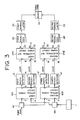
- Figure 3 is a block diagram of a receiver in a third embodiment according to the present invention;
- Figures 4A, 4B and 4C are circuit diagrams of optical hybrid circuits;
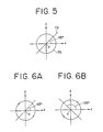
- Figure 5 is a graph showing a mode of polarization of a signal beam and a local-oscillator beam applied to the optical hybrid circuit of Fig. 4A or 4B;
- Figures 6A and 6B are graphs showing modes of polarization of a signal beam and a local-oscillator beam applied to the optical hybrid circuit of Fig 4A or 4B;
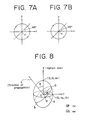
- Figures 7A and 7b are graphs showing further modes of polarization of a signal beam and a local-oscillator beam applied to the optical hybrid circuit of Fig. 4A or 4B;
- Figure 8 is a graph of assistance in explaining the circular polarization and elliptic polarization of linearly polarized light, showing an index ellipsoid;
- Figures 9A and 9B are circuit diagrams of double-balanced photodetectors;
- Figures 10A, 10B and 10C are circuit diagrams of optical hybrid circuits suitable for a double-balanced photodetector;
- Figures 11A and 11B are graphs of assistance in explaining the relative relation between a signal beam and a local-oscillator beam on the frequency axis;
- Figures 12A and 12B are graphs of assistance in explaining a state where the upper and lower sidebands are folded, and delay attributable to wavelength dispersion;
- Figures 13A and 13B are graphs of assistance in explaining the delaying characteristics of an equalizer necessary for the compensation of delay in a signal in the upper sideband and a signal in the lower sideband attributable to the wavelength dispersion; and
- Figure 14 is a block diagram of a receiver in a fourth embodiment according to the present invention.
- As shown in Fig. 1, in a first embodiment of the present invention, a receiver for coherent optical communication comprises: an optical
local oscillator 1 for emitting a local-oscillator beam; anoptical hybrid circuit 10 which is provided with a firstoptical input port 2 for receiving a signal beam, a secondoptical input port 4 for receiving the local-oscillator beam, a firstoptical output port 6 and a secondoptical output port 8, branches the signal beam and the local-oscillator beam, adds one pair of the branched beams pairs of each of the signal beam and the local-oscillator beam having a predetermined phase shift to the other pair respectively, and applies the added beams respectively to the firstoptical output port 6 and the secondoptical output port 8; afirst photodetector 12 for the photoelectric conversion sof a beam received from firstoptical output port 6; asecond photodetector 14 for the photoelectric conversion of a beam received from the secondoptical output port 8; an electrical 90°hybrid circuit 24 which is provided with anelectrical input port 16 for receiving the output signal of thefirst photodetector 12, asecond photodetector 14, a firstelectrical output port 20 and a secondelectrical output port 22, adds the signal received at the firstelectrical input port 16 to the signal received at the secondelectrical input port 18 after shifting the phase of the former by 90° to obtain an added signal and applies the added signal to the secondelectrical output port 22, adds the signal received at the secondelectrical input port 18 to the signal received at the firstelectrical input port 16 after shifting the phase of the former by 90°to obtain an added signal and applies the added signal to the firstelectrical output port 20; afirst equalizer 26 which delays a signal received from the firstelectrical output port 20 by a delay corresponding to the frequency of the same received signal; asecond equalizer 28 which delays a signal received fro the secondelectrical output port 22 by a delay corresponding to the frequency of the same received signal; afirst demodulator 30 which demodulates the output signal of thefirst equalizer 26, asecond demodulator 32 which demodulates the output signal of thesecond equalizer 28; and anadder 34 which adds the respective output signals of thefirst demodulator 30 and thesecond demodulator 32. - The proportional constant of either the
first equalizer 26 or thesecond equalizer 28, for determining the delay according to the frequency is positive and the sign of the proportional constant or the other, for determining the delay according to the frequency is negative. - As shown in Fig. 2, in a second embodiment of the present invention, a receiver for coherent optical communication comprises: an optical
local oscillator 1 for emitting a local-oscillator beam; anoptical hybrid circuit 10 which is provided with a firstoptical input port 2 for receiving the signal beam, a secondoptical input port 4 for receiving the local-oscillator beam, a firstoptical output port 6 and a secondoptical output port 8, branches the signal beam and the local-oscillator beam, adds one pair of the branched beams pairs of each of the signal beam and the local-oscillator beam having a predetermined phase shift to the other pair respectively, and applies the added beams respectively to the firstoptical output port 6 and the secondoptical output port 8; afirst photodetector 12 for the photoelectric conversion of a beam of the firstoptical output port 6; asecond photodetector 14 for the photoelectric conversion of a beam of the secondoptical output port 8; afirst branching circuit 36 for branching the output signal of thefirst photodetector 12; asecond branching circuit 38 for branching the output signal of thesecond photodetector 14; a first electrical 90°hybrid circuit 24A which is provided with a firstelectrical input port 16 which receives one of the output branched signals of thefirst branching circuit 36, a secondelectrical input port 18 which receives one of the output branched signals of thesecond branching circuit 38, a firstelectrical output port 20 and a secondelectrical output port 22, adds the signal applied to the firstelectrical input port 16 to the signal applied to the secondelectrical input port 18 after shifting the phase of the former by 90° to provide an added signal, applies the same added signal to the secondelectrical output port 22, adds the signal applied to the secondelectrical input port 18 to the signal applied to the firstelectrical input port 16 after shifting the phase of the former by 90° to obtain an added signal and applies the same added signal to the firstelectrical output port 20; aninverter 40 for inverting the polarity of the other output branched signal of either thefirst branching circuit 36 or thesecond branching circuit 38; a second electrical 90°hybrid circuit 24B which is provided with a firstelectrical input port 16 for receiving the other output branched signal, not applied to theinverter 40 for polarity inversion, a secondelectrical input port 18 for receiving the other branched signal inverted by theinverter 40, a firstelectrical output port 20 and a secondelectrical output port 22, adds the signal applied to the firstelectrical input port 16 to the signal applied to the secondelectrical input port 18 after shifting the phase of the former by 90° to provide an added signal, applies the same added signal to the secondelectrical output port 22, adds the signal applied to the secondelectrical input port 18 to the signal applied to the firstelectrical input port 16 after shifting the phase of the former by 90° to provide an added signal and applies the same added signal to the firstelectrical output port 20; afirst equalizer 26 and asecond equalizer 28′ which delay a signal received from the firstelectrical output port 20 of the first electrical 90° hybrid circuit 24a and a signal received from the secondelectrical output port 22 of the second electrical 90°hybrid circuit 24B by delays corresponding to their frequencies, respectively, or delay a signal received from the secondelectrical output port 22 of the first electrical 90° hybrid circuit 24a and a signal received from the firstelectrical output port 20 of the second electrical 90°hybrid circuit 24B by delays corresponding to their frequencies, respectively; afirst demodulator 30 for demodulating the output signal of thefirst equalizer 26; asecond demodulator 32 for demodulating the output signal of thesecond equalizer 28′; and anadder 34 for adding the output signals of thefirst demodulator 30 and thesecond demodulator 32. - The
equalizers - As shown in Fig. 3, in a third embodiment of the present invention, a receiver for coherent optical communication comprises: a first
optical branching circuit 42 for branching a received signal beam; a localoptical oscillator 1 which emits a local-oscillator beam; a secondoptical branching circuit 44 which branches the local-oscillator beam emitted by the localoptical oscillator 1; a firstoptical hybrid circuit 10A which is provided with a firstoptical input port 2 which receives one of the branched beams of the signal beam branched by the firstoptical branching circuit 42, a secondoptical input port 4 which receives one of the branched beams of the local-oscillator beam branched by the secondoptical branching circuit 44, a firstoptical output port 6 and a secondoptical output port 8, branches the signal beam and the local-oscillator beam, adds one pair of the branched beams pairs of each of the signal beam and the local-oscillator beam having a predetermined phase shift to the other pair respectively, and applies the added beams to the firstoptical output port 6 and the secondoptical output port 8, respectively; a second optical hybrid circuit 10B which is provided with a firstoptical input port 2 which receives the other branched beam of the signal beam branched by the firstoptical branching circuit 42, a secondoptical input port 4 which receives the other branched beam of the local-oscillator beam branched by the secondoptical branching circuit 44, a firstoptical output port 6 and a secondoptical output port 8, branches the signal beam and the local-oscillator beam, adds one pair of the branched beams pairs of each of the signal beam and the local-oscillator beam having a predetermined phase shift to the pair respectively, and applies the added beams to the firstoptical output port 6 and the secondoptical output port 8, respectively; first tofourth photodetectors optical output port 6 andsecond output port 8 of the firstoptical hybrid circuit 10A and the firstoptical output port 6 and secondoptical output port 8 of the second optical hybrid circuit 10B; a first electrical 90° hybrid circuit 24a which is provided with a firstelectrical input port 16 which receives the output signal of thefirst photodetector 12, a secondelectrical input port 18 which receives the output signal of thesecond photodetector 14, a firstelectrical output port 20 and a secondelectrical output port 22, adds the input signal applied to the firstelectrical input port 18 after shifting the phase of the former by 90° to provide an added signal, applies the same added signal to the secondelectrical output port 22, adds the input signal applied to the secondelectrical input port 18 to the input signal applied to thefirst input port 16 after shifting the phase of the former by 90° to provide an added signal and applies the same added signal to the firstelectrical output port 20; a second electrical 90° hybrid circuit 24b which is provided with a firstelectrical input port 16 which receives the output signal of thethird photodetector 12′, a secondelectrical input port 18 which receives the output signal of thefourth photodetector 14′, a firstelectrical output port 20 and a secondelectrical output port 22, adds the signal applied to the firstelectrical input port 16 to the signal applied to the secondelectrical input port 18 after shifting the phase of the former by 90°, applies the added signal to the secondelectrical output port 22, adds the signal applied to the secondelectrical input port 18 to the signal applied to the firstelectrical input port 16 after shifting the phase of the former by 90° and applies the added signal to the firstelectrical output port 20; afirst equalizer 26 and asecond equalizer 28′ which delay the output signals received from the firstelectrical output port 20 of the first electrical 90°hybrid circuit 24A and the secondelectrical output port 22 of the second electrical 90°hybrid circuit 24B by delays respectively corresponding to their frequencies, or delay the output signals received from the secondelectrical output port 22 of the first electrical 90° hybrid circuit 24a and the output signal of the firstelectrical output port 20 of the second electrical 90° hybrid circuit 24b by delays respectively corresponding to their frequencies; afirst demodulator 30 for demodulating the output signal of thefirst equalizer 26, asecond demodulator 32 for demodulating the output signal of thesecond equalizer 28′; and an adder for adding the output signals of thefirst demodulator 30 and thesecond demodulator 32. - The
first equalizer 26 and thesecond equalizer 28′ are the same in the sign of the ratio of change in delay to change in frequency. - In any one of the receivers in the first, the second and the third embodiments of the present invention, the electrical 90° hybrid circuit provides separately a signal based on the upper sideband and a signal based on the lower sideband folded on the baseband, so that the compensation of wavelength dispersion in an optical fiber can be achieved.
- Prior to the detailed description of receivers operation in preferred embodiments according to the present invention, the circuit configurations of optical hybrid circuits will be described with reference to Figs. 4A, 4B and 4C.
- An optical hybrid circuit shown in Fig. 4A comprises an
optical coupler 48 which adds the signal beam applied to the firstoptical input port 2 to the local-oscillator beam applied to the secondoptical input port 4 to provide a added beam and branches the added beam to provide branched beams, and apolarizing splitter 50 which splits at least one of the branched beams branched by theoptical coupler 48 so that the polarized components of the local-oscillator beam and the signal beam are applied to the firstoptical output port 6 and the secondoptical output port 8. - An optical hybrid circuit shown in Fig. 4B comprises a first
polarizing splitter 52 and a secondpolarizing splitter 54 which splits the signal beam received at the firstoptical input port 2 and the local-oscillator beam received at the secondoptical input port 4 so that the polarized components of the signal beam and the local-oscillator beam are provided, and twooptical couplers polarizing splitters first output port 6 and thesecond output port 8. - An optical hybrid circuit shown in Fig. 4C comprises two
optical couplers optical input port 2 and the secondoptical input port 4, anoptical coupler 64 which adds the signal beam (or the local-oscillator beam) branched by theoptical coupler 60 to the local-oscillator beam (or the signal beam) branched by theoptical coupler 62 and applies the added beam to the firstoptical output port 6, aphase shifter 66 which shifts the phase of the signal beam (or the local-oscillator beam) branched by theoptical coupler 60 by 90°, and anoptical coupler 68 which adds the signal beam (or the local-oscillator beam) branched by theoptical coupler 60 and phase-shifted by thephase shifter 66 to the local-oscillator beam (or the signal beam)branched by theoptical coupler 62 and applies the added beam to a secondoptical output port 8. - For the optical hybrid circuit shown in Fig. 4A or 4B, the signal beam or the local-oscillator beam is applied to the first
optical input port 2 in a linearly polarized beam and the other is applied to the second optical input port 4in a circularly polarized beam, or the signal beam and the local-oscillator beam are applied respectively to the firstoptical input port 2 and the secondoptical input port 4 in elliptically polarized beams having a phase shift equal to the phase difference between the linear-polarized beam and the circular-polarized beam. For the optical hybrid circuit shown in Fig. 4C, the signal beam and the local-oscillator beam are applied in linearly polarized beams respectively to the firstoptical input port 2 and the secondoptical input port 4. The optical path length is adjusted and the plane of polarization is secured so that the polarized state is maintained as far as the light receiving surface. - The signal beam and the local-oscillator beam are applied to the optical hybrid circuit in such specific states of polarization to realize a phase diversity system by branching the received signal beam into two branch beams, adding the 90°-shifted local-oscillator beam to the branched signal beams and making the added beams reach the light receiving surfaces.
- Each optical coupler may be of a fiber fusion type utilizing evanescent wave coupling or of a waveguide type, desirably, an optical coupler capable of conserving the plane of polarization. The optical couplers may be half mirrors.
- Fig. 5 shows a graph of assistance in explaining a desirable state of polarization of the signal beam and the local-oscillator beam applied to the optical hybrid circuit shown in Fig. 4A or 4B included in the receiver shown in Fig. 1 or 2, in which the direction of light propagation coincides with that of the z-axis, the plane of polarization of a P-polarized beam divided by the polarizing splitter is included in the x-z plane and the plane of polarization of an S-polarized beam is included in the y-z plane of an orthogonal three-dimensional coordinate system, which applies also to Figs. 6 and 7. The state of polarization of the signal beam and that of the local-oscillator beam may be interchanged. In the following description, it is assumed that the signal beam is a linearly polarized beam and the local-oscillator beam is a circularly polarized beam. In Fig. 5, as circle of 70 is the projection of the locus of the tip of the field vector of the local-oscillator beam propagating in a circularly polarized beam on the x-y plane, and a
line segment 72 is the projection of the locus of the extremity of the field vector of the signal beam propagating in a linearly polarized beam on the x-y plane. The local-oscillator beam 70 may be either a clockwise circularly polarized beam or a counterclockwise circularly polarized beam with respect to the direction of propagation. When thesignal beam 72 is a 45° linearly polarized beam having a plane of polarization inclined at an angle of 45° to the positive direction of the x-axis in a counterclockwise direction, the branched signal beams divided by the polarizing splitter are equal to each other in power and hence optical powers that appear respectively at the firstoptical output port 6 and the secondoptical output port 8 are equal to each other to enhance the receiving sensitivity. Hereinafter, a linearly polarized beam having a plane of polarization inclined at an angle of ϑ° to the positive direction of the x-axis in a counterclockwise direction will be designated as a ϑ° linearly polarized beam. - When the local-
oscillator beam 70 and thesignal beam 72 of such characteristics are applied respectively, for example, to the firstoptical input port 2 and secondoptical input port 4 of the optical hybrid circuit shown in Fig. 4A, theoptical coupler 48 adds the local-oscillator beam 70 and thesignal beam 72, and thepolarizing splitter 50 splits the same. The phase shift between the split signal beams is zero, but the phase shift between the split local-oscillator beams is at thepolarizing splitter 50. The 90°-shifted local-oscillator beams are added to the branched signal beams and the added beams are applied to the firstoptical output port 6 and the secondoptical output port 8. - When the
signal beam 72 and the local-oscillator beam 70 are applied respectively to the firstoptical input port 2 and secondoptical input port 4 of the optical hybrid circuit shown in Fig. 4B, the optical hybrid circuit adds the 90°-shifted local-oscillator beams to the branched signal beams and applies the added beams respectively to the firstoptical output port 6 and the secondoptical output port 8 after performing light beam adding and light beam branching in order reverse to that in which the optical hybrid circuit shown in Fig. 4A performs the same. - Figs. 6A and 6B are graphs of assistance in explaining desirable states of polarization of a signal beam and a local-oscillator beam applied to the optical hybrid circuit shown in Figs. 4A and/or 4B included in a receiver shown in Fig. 3. When a signal beam and a local-oscillator beam applied to either the first optical
hybrid circuit 10A or the second optical hybrid circuit 10B are a 45° linearly polarized beam and a clockwise circularly polarized beam, as shown in Fig. 6A, respectively, a 135° linearly polarized beam and a clockwise circularly polarized beam as shown in Fig. 6B are applied as a signal beam and a local-oscillator beam, respectively, to the other optical hybrid circuit. Thus, the two optical hybrid circuits shift the phase of the local-oscillator beam in reverse directions, respectively. For example, when the phase of the local-oscillator beam added to the signal beam to be applied to the firstoptical port 6 of one of the two optical hybrid circuits is advanced by 90° relative to the phase of the local-oscillator beam added to the signal beam to be applied to the secondoptical output port 8 of the same optical hybrid circuit, the phase of the local-oscillator beam added to the signal beam to be applied to the firstoptical output port 6 of the other optical hybrid circuit can be delayed by 90° relative to the local-oscillator beam added with the signal beam to be applied to the secondoptical output port 8 of the same optical hybrid circuit. - When a signal beam and a local-oscillator beam applied to one of the two optical hybrid circuits are a 45° linearly polarized beam and a clockwise circularly polarized beam as shown in Fig. 7A, respectively, the respective phase shifting directions of the two optical hybrid circuits in shifting the phases of the local-oscillator beams applied respectively to the two optical hybrid circuits can be reverse to each other when a signal beam and a local-oscillator beam applied to the other optical hybrid circuit are a 45° linearly polarized beam and a counterclockwise circularly polarized beam as shown in Fig. 7B, respectively.
- When the receiver in the first or second embodiment of the present invention employs the optical hybrid circuit shown in Fig. 4C, the interference efficiency can be increased to a maximum by using linearly polarized beams having planes of polarization coinciding with each other as the input signal beam and the input local-oscillator beam and by maintaining the coincidence of the planes of polarization as far as the light receiving surfaces to increase the receiving sensitivity to a maximum.
- When the receiver in the third embodiment of the invention employs the optical hybrid shown in Fig. 4C, the phase shift produced by one of the
phase shifters 66 is +90° when the phase shift produced by the other is -90° (+270°). - Although the description made with reference to Figs. 5 to 7B is based on an assumption that the signal beam and the local-oscillator beam applied to the optical hybrid circuit shown in Fig. 4A or 4B are a linearly polarized beam and a circularly polarized beam, respectively, the signal beam and the local-oscillator beam applied respectively to the first
optical input port 2 and the secondoptical input port 4 may be elliptically polarized beams, which will be described hereinafter with reference to Fig. 8. - Fig. 8 shows an index ellipsoid of assistance in explaining circular polarization and elliptic polarization. Generally, when a local-oscillator beam is emitted by a local light source, such as a laser diode, in a linearly polarized beam like the
signal beam 72 shown in Fig. 5, the linearly polarized local-oscillator beam can be converted into a circularly polarized beam by using a quarter wavelength plate which functions at different refractive indices respectively with a polarized component having a plane of polarization included in the x-z plane and a polarized component having a plane of polarization included in the y-z plane. The quarter wavelength plate is a birefringent plate having a given thickness and disposed in a given crystal orientation. Suppose that the refractive index of the birefringent plate with an ordinary beam is no, a maximum refractive index of the same with an extraordinary beam is ne (no < ne), a light beam is traveling in the direction of an arrow S from the origin O of an orthogonal three-dimensional coordinate system having the z-axis coinciding with the optical axis of the birefringent plate, and the projection of the arrow S on the X-Y plane is included in the Y-axis. Then, the index ellipsoid is expressed by
(X²/no²) + (Y²/no²) + (Z²/ne²) = 1 (1)
The refractive index no with the ordinary beam is a constant corresponding to the distance OP between the origin O and a point P where a circle A obtained by intersecting the index ellipsoid with the X-Y plane intersects an ellipse B obtained by intersecting the index ellipsoid with a plane including the origin O and perpendicular to the direction S of propagation. The refractive index ne′ with the extraordinary beam varies according to the angle ϑ between the direction S of propagation and the Z-axis and corresponds to the distance OQ between the origin O and a point Q where the ellipse B intersects the Y-Z plane. The refractive index ne′ with the extraordinary beam varies continuously between no and ne according to the direction S of propagation. Since the difference between the refractive index of the birefringent plate with the ordinary beam and that of the same with the extraordinary beam varies according to the direction S of propagation of the extraordinary beam, the input local-oscillator beam, i.e., the linearly polarized beam can be converted into a circularly polarized beam by disposing orienting the optical axis of the birefringent plate so that the direction S of propagation of the local-oscillator beam coincides with the Y-axis (ϑ = 90°) so that the plane of polarization of the local-oscillator beam inclined at an angle of 45° to the lines OP and OQ and by selectively determining the thickness of the birefringent plate so that the phase difference between the orthogonal polarized components of the local-oscillator beam is 90°. - Accordingly, it is possible to use an elliptically polarized beam having an appropriate ellipticity as either the signal beam or the local-oscillator beam, and an elliptically polarized beam having a corresponding ellipticity as the other beam, and to make the phase relation between the elliptically polarized beams correspond to the phase relation between a linearly polarized beam and a circularly polarized beam by utilizing the characteristics of the birefringent plate.
- Two dual-detector balanced optical receivers (DBORs) of different circuit configurations will be described hereinafter with reference to Figs. 9A and 9B.
- The DBOR shown in Fig. 9A amplifies voltage changes corresponding to photocurrent changes in two
light receiving elements amplifiers light receiving elements light receiving elements light receiving elements amplifier 88. - When the DBOR is employed, the output signal beams and the output local oscillator beams of the optical hybrid circuit must be applied through two paths to the two light receiving elements, and hence the configurations of the optical hybrid circuits shown in figs. 4A, 4B and 4C must be modified. Figs. 10A, 10B and 10C are modifications of the optical hybrid circuits shown in Figs. 4A, 4B and 4C, respectively.
- An optical hybrid circuit shown in Fig. 10A is provided, in addition to the
polarizing splitter 50 for splitting one of the beams branched by theoptical coupler 48, apolarizing splitter 90 for splitting the other beam. P waves split by thepolarizing splitters optical output ports optical output 6. S waves split by thepolarizing splitters optical output ports optical output port 8. The two P waves and the two S waves are applied through optical paths having appropriate optical path lengths respectively to the twolight receiving elements - An optical hybrid circuit shown in Fig. 10B branches each of added beams added by the
optical couplers optical coupler 56 is applied to theoptical output ports optical output port 6, and the optical outputs of theoptical coupler 58 are applied to theoptical output ports optical output port 8. - An optical hybrid circuit shown in Fig. 10C, similarly to that shown in Fig. 10B, applies the respective two optical outputs of two
optical couplers optical output port 6 and the secondoptical output port 86. - The concrete circuit configuration and functions of the electrical 90°
hybrid circuit 24 employed in the receiver embodying the present invention will be described hereinafter. - The electrical 90°
hybrid circuit 24 transmits a signal from the firstelectrical input port 16 to the firstelectrical output port 20 and from the secondelectrical input port 18 to the secondelectrical output port 22 at 3 dB loss without changing the phase of the signal, and transmits a signal from the firstelectrical input port 16 to the secondelectrical output port 22 and from the secondelectrical input port 18 to the first electrical output port at 3 dB loss changing the phase of the signal by 90°. The circuit configuration is changed according to the frequency band of the signal. - Delays given to signals by the
equalizers equalizers - When the
demodulator demodulators - The characteristic operation of the receivers in the first to third embodiments according to the present invention will be described hereinafter.
- Assuming that the receiver in the first embodiment operates in a PSK mode,
ES = C₁ cos (ωSt + φ) (2)
where ES is the field intensity of the input signal beam, C₁ is an optional constant, ωS is the angular frequency of the carrier, φ is the phase difference between the electric field of the signal beam and that of the local-oscillator beam, which remains constant in one time slot (the reciprocal of bit rate). The signal beam is divided by theoptical hybrid circuit 10 into two branch signal beams, the two branch signal beams are added to the local-oscillator beams of angular frequency having 90° phase difference, and the added beams are subjected to the square-law detection of thephotodetectors photodetectors
I₁ = C₂ cos (ωOFFt + φ) (3)
I₂ = -C₂ sgn(ωS - ωL)·sin (ωOFFt _ φ) (4)
where C₂ is an optional constant, ωOFF is offset angular frequency for the AFC (automatic frequency control) of the local-oscillator beam expressed by
ωOFF = |ωS ¡- ωL| (5)
- The sgn(ωS - ωL) is defined by
sgn (ωS - ωL) = 1 (ωS - ωL >0) = -1 (ωS - ωL < 0) (6) - To facilitate qualitative understanding, expressions (3) and (4) are changed as follows taking into consideration only the relative relation between these phases.
I₁ = cost ωt (7)
I₂ = sgn(ωS - ωL)·sin ωt (8) - Similarly, input signals I₃ and I₄ to the additional electrical 90°
hybrid circuit 24B included in the receiver in the second or third embodiment are
I₃ = cos ωt (9)
I₄ = sgn(ωS - ωL)·sin ωt (8) - Representing an operation for delaying the phase by 90° by "*",
(cos ωt)* = sin ωt (11)
(sin ωt)* = -cos ωt (12)
Output signals O₁, O₂, O₃ and O₄ corresponding to the inputs to the electrical 90°hybrid circuit 24 are
O₁ = 1/√2·(I₁ + I₂*) = 1/√2·(1 + sgn(ωS - ωL))·cos ωt (13)
O₂ = 1/√2·(I₁* + I₂) = 1/√2·(1 - sgn(ωS - ωL))·sin ωt (14)
O₃ = 1/√2·(I₃ + I₄*) = 1/√2·(1 - sgn(ωS - ωL))·cos ωt (15)
O₄ = 1/√2·(I₃* + I₄) = 1/√2·(1 + sgn(ωS - ωL))·sin ωt (16) - The following table shows the contents of expressions (13) to (16).
- As shown in the table, the electrical 90° hybrid circuit provides output signals in the upper sideband and those in the lower sideband separately, and hence signal degradation attributable to wavelength dispersion can be prevented by delaying the output signals according to their frequencies by the equalizers, which will be described below with reference to Figs. 11 to 13.
Table Output signal O₁ O₂ O₃ O₄ O < ωS - ωL (upper sideband) √2·cos ωt 0 0 √2·sin ωt O > ωS - ωL (lower sideband) 0 √2· sin ωt √ 2·cos ωt 0 - In the phase diversity system, the relation between the frequency fS of the signal beam and the frequency fL of the local-oscillator bed is fL < fS (Fig. 11A) or fS < fL (Fig. 11B). In either case, the upper sideband (continuous line) and lower sideband (broken line) of the output signals of the
photodetectors - In the receivers in the first to third embodiments of the present invention, the electrical 90°
hybrid circuit 24 is able to provide the upper sideband signal and the lower sideband signal separately. Therefore, the wavelength dispersion can be compensated by using an equalizer which gives greater delays for higher frequencies for the upper sideband signal, and an equalizer which gives smaller delays for higher signal frequencies for the lower sideband signal. - In the receiver in the first embodiment of the present invention, the output signals O₁ and O₂ of the electrical 90°
hybrid circuit 24 are an upper sideband signal and a lower sideband signal as shown in the table. Therefore, the respective characteristics of theequalizers hybrid circuit 24A and the second electrical 90°hybrid circuit 24B are used, and hence theequalizers - In the receivers in the first to third embodiments of the present invention, the upper sideband signal and the lower sideband signal are separated from each other on a principle similar to an image rejection principle. Therefore, dispersion in each signal must be compensated by an equalizer to realize phase diversity. Accordingly, at least two equalizers are necessary. A receiver in a fourth embodiment of the present invention functions properly on a single equalizer.
- Fig. 14 is a block diagram of the receiver in the fourth embodiment according to the present invention. An optical
local oscillator 1 comprises a light source (laser diode) 92 and a drivingcircuit 94 which drives thelight source 92 by controlling the oscillation frequency through the control of the bias current supplied to thelight source 92. The opticallocal oscillator 1 comprises further anoptical hybrid circuit 10 and an electrical 90°hybrid circuit 24, which are similar to those of the first to third embodiments, respectively. The output signal of aphotodetector 12 is added with the output signal of an oscillator by amixer 98 for up-conversion and the added signal is applied to an electrical 90°hybrid circuit 24. The output signal of aphotodetector 14 is added with the output signal of theoscillator 96 by amixer 100 for up-conversion and the added signal is applied to the electrical 90°hybrid circuit 24. An output signal of the electrical 90°hybrid circuit 24 at a firstelectrical output port 20 is applied through anequalizer 26 to ademodulator 30. An output signal of the electrical 90°hybrid circuit 24 at a secondelectrical output port 24 is applied to afrequency discriminator 102. The oscillation frequency of thelocal oscillator 1 is controlled in a feedback control mode so that the frequency of the input signal to thefrequency discriminator 102 is constant. - The output photocurrents I₁ and I₂ of the
photodetectors - The two electrical signals obtained by optical detection are added by
mixers oscillator 96 having an angular frequency ωIF (» ωOFF).
I = C₃ cos ωIFt (17)
where C₃ is an optional constant. The output currents i₁ and i₂ of themixers
i₁ = C₄ cos (ωOFFt + φ)cos ωIFt = C₄ cos A·cos B = (C₄/2){cos (A + B) + cos (B - A)} (18)
i₂ = -C₄ sin (ωOFFt + φ)cos ωIFt = -C₄ sin ∇·cos B = (-C₄/2){sin (A + B) - sin (B - A)} (19)
where C₄ is an optional constant and
A = ωOFFt + φ (20)
B = ωIFt (21) - Conversion for delaying phase by 90° is represented by "*" and
cos(A + B) = α (22)
cos (B - A) = β (23)
Then,
α* = sin (A + B)
β* = cos (B - A)
Therefore expressions (18) and (19) can be rewritten as
i₁ = (C₄/2)(α + β) (24)
i₂ = (-C₄/2)(α* - β*) (25) - Accordingly, when the frequency-up-converted currents i₁ and i₂ are supplied to the electrical 90°
hybrid circuit 24, the outputs of the electrical 90°hybrid circuit 24 are
j₁ = i₁/2 + i₂*/2 = (C₄/4)(α + β) - (C₄/4)(α* - β*)* = (C₄/2)α = (C₄/2)cos {(ωIF + ωOFF)t + φ} (26)
j₂ = i₁*/2 + i₂/2 = (C₄/4)(α + β)* - (C₄/4)(α* -β*) =(C₄/2)β* = (C₄/2)sin {(ωIF - ωOFF)t + φ) (27) - It is obvious from expression (26) that a photocurrent equal to that obtained through heterodyne detection using the IF (ωOFF + ωIF) is obtained. Accordingly, similarly to the procedure in the ordinary heterodyne system, the
demodulator 30 is able to provide a baseband signal after applying the output current j₁ to theequalizer 26 to compensate dispersion in the optical fiber. Thus, the receiver in the fourth embodiment is effective for the enhancement of transmission speed and realizes a phase diversity system not requiring a light source with a very narrow spectral line width. Furthermore, the receiver is capable of compensating dispersion in the optical fiber. The output currents j₁ and j₂ may be used respectively for the AFC of the opticallocal oscillator 1 and the baseband signal demodulation. - The present invention is not limited to the foregoing specific embodiments in its practical application. For example, the optical hybrid circuit comprising, in combination, the components respectively for particular functions, such as optical couplers, may be substituted by a single device comprising a waveguide substrate carrying elements corresponding to all those components of the optical hybrid circuit to provide a compact receiver. Such a device provided with the light receiving elements of photodetectors directly formed on the waveguide substrate secures an accurate optical distance between the light receiving element and the optical coupler or the polarizing splitter to improve the reliability of the receiver.
- Although the invention has been described in its preferred forms with a certain degree of particularity, obviously many changes and variations are possible therein. It is therefore to be understood that the present invention may be practiced otherwise than as specifically described herein without departing from the scope and spirit thereof.
Claims (27)
an optical local oscillator which emits a local-oscillator beam;
an optical hybrid circuit which is provided with a first optical input port for receiving a signal beam, a second optical input port for receiving the local-oscillator beam, a first optical output port and a second optical output port, branches the signal beam and the local-oscillator beam, adds one pair of the branched beams pairs of each of the signal beam and the local-oscillator beam, having a predetermined phase shift to the other pair respectively, and applies the added beams respectively to the first and second optical output ports;
a first photodetector for the photoelectric conversion of a beam received from the first optical output port of the optical hybrid circuit;
a second photodetector for the photoelectric conversion of a beam received from the second optical output port of the optical hybrid circuit;
an electrical 90° hybrid circuit which is provided with first and second electrical input ports for receiving the output signals of the first and second photodetectors, respectively, and first and second electrical output ports, adds the signal received at the first electrical input port to the signal received at the second electrical input port after shifting the phase of the former by 90° to obtain a added signal and applies the added signal to the second electrical output port, adds the signal received at the second electrical input port to the signal received at the first electrical input port after shifting the phase of the former by 90° to obtain a added signal and applies the added signal to the first electrical output port;
a first equalizer which delays a signal received from the first electrical output port by a delay corresponding to the frequency of the same received signal;
a second equalizer which delays a signal received from the second electrical output port by a delay corresponding to the frequency of the same received signal;
a first demodulator which demodulates the output signal of the first equalizer;
a second demodulator which demodulates the output signal of the second equalizer; and
an adder which adds the respective output signals of the first and second demodulators.
an optical local oscillator which emits a local-oscillator beam;
an optical hybrid circuit which is provided with a first optical input port for receiving a signal beam, a second optical input port for receiving the local-oscillator beam, a first optical output port and a second optical output port, branches the signal beam and the local-oscillator beam, adds one pair of the branched beams pairs of each of the signal beam and the local-oscillator beam having a predetermined chase shift to the other pair respectively, and applies the added beams respectively to the first and second optical output ports;
a first photodetector for the photoelectric conversion of a beam received from the first optical output port;
a second photodetector for the photoelectric conversion of a beam received from the second optical output port;
a first branching circuit for branching the output signal of the first photodetector;
a second branching circuit for branching the output signal of the second photodetector;
a first electrical 90° hybrid circuit which is provided with a first electrical input port which receives one of the output branched signals of the first branching circuit, a second electrical input port which receives one of the output branched signals of the second branching circuit, a first electrical output port and a second electrical output port, adds the signal applied to the first electrical input port to the signal applied to the second electrical input port after shifting the phase of the former by 90° to provide a added signal and applies the same added signal to the second electrical output port, adds the signal applied to the second electrical input port to the signal applied to the first electrical input port after shifting the phase of the former by 90° to provide a added signal and applies the same added signal to the first electrical output port;
an inverter for inverting the polarity of the other output branched signal of either the first branching circuits or the second branching circuit;
a second electrical 90° hybrid circuit which is provided with a first electrical input port for receiving one of the other output branched signals, not applied to the inverter for polarity inversion, a second electrical input port for receiving the other output branched signal inverted by the inverter, a first electrical output port and a second electrical output port, adds the signal applied to the first electrical input port to the signal applied to the second electrical input port after shifting the phase of the former by 90° to obtain a added signal and applies the same added signal to the second electrical output port, adds the signal applied to the second electrical input port to the signal applied to the first electrical input port after shifting the phase of the former by 90° to obtain a added signal and applies the same added signal to the first electrical output port;
first and second equalizers which delay a signal received from the first electrical output port of the first electrical 90° hybrid circuit and a signal received from the second electrical output port of the second electrical 90° hybrid circuit by delays corresponding to their frequencies, respectively, or delay a signal received from the second electrical output port of the first electrical 90° hybrid circuit and a signal received from the first electrical output port of the second electrical 90° hybrid circuit by delays corresponding to their frequencies;
a first demodulator for demodulating the output signal of the first equalizer;
a second demodulator for demodulating the output signal of the second equalizer; and
an adder for adding the output signals of the first and second demodulators.
an optical local oscillator which emits a local-oscillator beam;
an optical hybrid circuit which is provided with a first optical input port which receives a signal beam, a second optical input port which receives the local-oscillator beam, a first optical output port and a second optical output port, branches the signal beam and the local-oscillator beam, adds one pair of the branched beams pairs of each of the signal beam and the local-oscillator beam, having a predetermined phase shift to the other pair respectively, and applies the added beams respectively to the first and second optical output ports;
a first photodetector for the photoelectric conversion of a beam received from the first optical output port of the optical hybrid circuit;
a second photodetector for the photoelectric conversion of a beam received from the second optical output port of the optical hybrid circuit;
an oscillator having a fixed frequency;
a first mixer which adds the output signal of the oscillator with the signal received from the first photodetector;
a second mixer which adds the output signal of the oscillator with the signal received from the second photodetector;
an electrical 90° hybrid circuit which is provided with a first electrical input port which receives the output signal of the first mixer, a second electrical input port which receives the output signal of the second mixer, a first electrical output port and a second elec trical output port, adds the signal applied to the first electrical input port to the signal applied to the second electrical input port after shifting the phase of the former by 90° to provide a added signal and applies the same added signal to the second electrical output port, adds the signal applied to the second electrical input port to the signal applied to the first electrical input port after shifting the phase of the former by 90° to provide a added signal and applies the same added signal to the first electrical output port; and
an equalizer which delays the output signal received from the first or second electrical output port by a delay corresponding to its frequency.
a first optical branching circuit for branching a received signal beam;
an optical local oscillator which emits a local-oscillator beam;
a second optical branching circuit for branching the local-oscillator beam;
a first optical hybrid circuit which is provided with a first optical input port which receives one of the branched beams of the signal beam branched by the first optical branching circuit, a second optical input port which receives one of the branched beams of the local-oscillator beam branched by the second optical branching circuit, a first optical output port and a second optical output port, branches the signal beam and the local-oscillator beam, adds one pair of the branched beams pairs of each of the signal beam and the local-oscillator beam having a predetermined phase shift to the other pair respectively, and applies the added beams to the first and second optical output ports, respectively;
a second optical hybrid circuit which is provided with a first optical input port which receives the other branched beam of the signal beam branched by the first optical branching circuit, a second optical input port which receives the other branched beam of the local-oscillator beam branched by the second optical branching circuit, a first optical output port and a second optical output port, branches the signal beam and the local-oscillator beam, adds one pair of the branched beams pairs of each of the signal beam and the local-oscillator beam having a predetermined phase shift to the other pair respectively, and applies the added beams to the first and second optical output ports, respectively;
first to fourth photodetectors respectively for the photoelectric conversion of the output beams received from the first and second optical output ports of the first optical hybrid circuit and the first and second output ports of the second optical hybrid circuit;
a first electrical 90° hybrid circuit which is provided with a first electrical input port which receives the output signal of the first photodetector, a second electrical input port which receives the output signal of the second photodetector, a first electrical output port and a second electrical output port, adds the input signal applied to the first electrical input port to the input signal applied to the second electrical input port after shifting the phase of the former by 90° to obtain a added signal, applies the same added signal to the second electrical output port, adds the input signal applied to the second electrical input port to the input signal applied to the first input port after shifting the phase of the forner by 90° to obtain a added signal and applies the same added signal to the first electrical output port;
a second electrical 90° hybrid circuit which is provided with a first electrical input port which receives the output signal of che third photodetector, a second electrical input port which receives the output signal of the fourth photodetector, a first electrical output port and a second electrical output port, adds the signal applied to the first electrical input port to the signal applied to the second electrical input port after shifting the phase of the former by 90° to obtain a added signal, applies the same added signal to the second electrical output port, adds the signal applied to the second electrical input port to the signal applied to the first electrical input port after shifting the phase of the former by 90° to provide a added signal and applies the same added signal to the first electrical output port;
first and second equalizers which delay the output signals received from the first electrical output port of the first electrical 90° hybrid circuit and the second electrical output port of the second electrical 90° hybrid circuit by delays respectively corresponding to their frequencies, or delay the output signals received from the second electrical output port of the first electrical 90° hybrid circuit and the output signal received from the first electrical output port of the second electrical 90° hybrid circuit by delays respectively corresponding to their frequencies;
first and second demodulators respectively for demodulating the output signals of the first and second equalizers; and
an adder for adding the output signals of the first and second demodulators.
Applications Claiming Priority (4)
| Application Number | Priority Date | Filing Date | Title |
|---|---|---|---|
| JP185906/89 | 1989-07-20 | ||
| JP1185906A JP2758215B2 (en) | 1989-07-20 | 1989-07-20 | Receiver for coherent optical communication |
| JP1206635A JP2758221B2 (en) | 1989-08-11 | 1989-08-11 | Receiver for coherent optical communication |
| JP206635/89 | 1989-08-11 |
Publications (3)
| Publication Number | Publication Date |
|---|---|
| EP0409260A2 true EP0409260A2 (en) | 1991-01-23 |
| EP0409260A3 EP0409260A3 (en) | 1993-01-27 |
| EP0409260B1 EP0409260B1 (en) | 1997-05-07 |
Family
ID=26503404
Family Applications (1)
| Application Number | Title | Priority Date | Filing Date |
|---|---|---|---|
| EP90113950A Expired - Lifetime EP0409260B1 (en) | 1989-07-20 | 1990-07-20 | Receiver for coherent optical communication |
Country Status (4)
| Country | Link |
|---|---|
| US (1) | US5115332A (en) |
| EP (1) | EP0409260B1 (en) |
| CA (1) | CA2021561C (en) |
| DE (1) | DE69030634T2 (en) |
Cited By (5)
| Publication number | Priority date | Publication date | Assignee | Title |
|---|---|---|---|---|
| FR2703201A1 (en) * | 1993-03-26 | 1994-09-30 | Ericsson Telefon Ab L M | System and method for compensating for dispersion occurring in high speed fiber optic systems. |
| FR2704702A1 (en) * | 1993-04-30 | 1994-11-04 | Ericsson Telefon Ab L M | Dispersal compensating device and method in an optical fiber transmission system |
| WO2002029456A2 (en) * | 2000-10-02 | 2002-04-11 | Charles Romaniuk | Phase dependent splitter/combiner 4-port coupler device |
| EP1209827A2 (en) * | 2000-11-28 | 2002-05-29 | AT&T Corp. | Method for diversity receiver for mitigating the effects of fiber dispersion by separate detection of two transmitted sidebands |
| EP1213858A2 (en) * | 2000-11-28 | 2002-06-12 | AT&T Corp. | System for diversity receiver for mitigating the effects of fiber dispersion by separate detection of two transmitted sidebands |
Families Citing this family (38)
| Publication number | Priority date | Publication date | Assignee | Title |
|---|---|---|---|---|
| NL9100292A (en) * | 1991-02-19 | 1992-09-16 | Nederland Ptt | OPTICAL TRANSMITTER AND RECEIVER WITH OPTICAL CIRCULATOR. |
| US5532865A (en) * | 1992-10-09 | 1996-07-02 | Matsushita Electric Industrial Co., Ltd. | Fiber optic communication terminal, fiber optic communication system, and its wavelength setting method |
| US5473463A (en) * | 1993-05-13 | 1995-12-05 | Koninklijke Ptt Nederland N.V. | Optical hybrid |
| WO1995028042A1 (en) * | 1994-04-12 | 1995-10-19 | Philips Electronics N.V. | Heterodyne receiver having low intermediate frequency |
| US5574589A (en) * | 1995-01-09 | 1996-11-12 | Lucent Technologies Inc. | Self-amplified networks |
| US5673133A (en) * | 1995-04-14 | 1997-09-30 | Nippon Telegraph And Telephone Corporation | Phase synchronization system |
| US20040161245A1 (en) * | 1996-12-20 | 2004-08-19 | Bergano Neal S. | Synchronous amplitude modulation for improved performance of optical transmission systems |
| US6556326B2 (en) * | 1996-12-20 | 2003-04-29 | Tyco Telecommunications (Us) Inc. | Synchronous amplitude modulation for improved performance of optical transmission systems |
| US6775484B1 (en) | 1997-06-03 | 2004-08-10 | Alcatel Alsthom Compagnie Generale D'electricite | Receiver for receiving optical signals |
| US7110677B2 (en) * | 2001-09-26 | 2006-09-19 | Celight, Inc. | Method and system for optical time division multiplexed fiber communications with coherent detection |
| US6473222B2 (en) | 2000-12-27 | 2002-10-29 | John N. Hait | Hyper-heterodyning, expanded bandpass apparatus and method |
| US6407848B1 (en) | 2000-12-27 | 2002-06-18 | All Optical Networks, Inc. | Servo-stabilized-phase, differential coherence detector |
| US7599627B2 (en) | 2001-05-31 | 2009-10-06 | Teradvance Communications, Llc | Method and system for a polarization mode dispersion tolerant optical homodyne detection system with optimized transmission modulation |
| US7945174B2 (en) * | 2001-09-26 | 2011-05-17 | Celight, Inc. | Secure optical communications system and method with coherent detection |
| JP3808820B2 (en) * | 2002-10-08 | 2006-08-16 | 日本電信電話株式会社 | Optical sampling method, apparatus and program |
| US7460793B2 (en) * | 2002-12-11 | 2008-12-02 | Michael George Taylor | Coherent optical detection and signal processing method and system |
| US7054012B2 (en) * | 2003-06-09 | 2006-05-30 | Agilent Technologies, Inc | Spectral phase measurement using phase-diverse coherent optical spectrum analyzer |
| US7330669B2 (en) * | 2004-04-20 | 2008-02-12 | Lucent Technologies Inc. | Optical heterodyne receiver based on oversampling |
| US7477852B2 (en) * | 2005-01-31 | 2009-01-13 | Alcatel-Lucent Usa Inc. | Optical receiver apparatus and method |
| US7650084B2 (en) * | 2005-09-27 | 2010-01-19 | Alcatel-Lucent Usa Inc. | Optical heterodyne receiver and method of extracting data from a phase-modulated input optical signal |
| US7406269B2 (en) * | 2006-03-10 | 2008-07-29 | Discovery Semiconductors, Inc. | Feedback-controlled coherent optical receiver with electrical compensation/equalization |
| US7835650B2 (en) * | 2006-07-11 | 2010-11-16 | Drexel University | Optical domain frequency down-conversion of microwave signals |
| WO2008038337A1 (en) * | 2006-09-26 | 2008-04-03 | Hitachi Communication Technologies, Ltd. | Optical electric field receiver and optical transmission system |
| US8204378B1 (en) | 2008-03-27 | 2012-06-19 | Tektronix, Inc. | Coherent optical signal processing |
| US8213752B2 (en) * | 2008-06-09 | 2012-07-03 | Chapman David J | Coherent optical mixer and a method of coherent detection of light |
| KR20110030136A (en) * | 2009-09-17 | 2011-03-23 | 한국전자통신연구원 | Polarization splitter, optical hybrid and optical receiver comprising the same |
| JP5796934B2 (en) * | 2010-04-13 | 2015-10-21 | 日本オクラロ株式会社 | Polarization diversity optical system device, demodulator and transceiver |
| US8923707B2 (en) * | 2010-06-14 | 2014-12-30 | Infinera Corporation | Apparatus for compensating optical signal impairments |
| US8995836B2 (en) * | 2010-07-13 | 2015-03-31 | Futurewei Technologies, Inc. | Passive optical network with adaptive filters for upstream transmission management |
| CN102087421B (en) * | 2010-12-03 | 2012-05-30 | 武汉光迅科技股份有限公司 | Crystal-type optical mixer for coherent optical communication |
| WO2015023255A1 (en) | 2013-08-12 | 2015-02-19 | Halliburton Energy Services, Inc | Systems and methods for spread spectrum distributed acoustic sensor monitoring |
| US9337937B2 (en) | 2014-03-10 | 2016-05-10 | Cisco Technology, Inc. | Common mode rejection ratio control for coherent optical receivers |
| WO2016033199A1 (en) | 2014-08-28 | 2016-03-03 | Adelos, Inc. | Real-time fiber optic interferometry controller |
| CN107409000B (en) * | 2015-04-10 | 2019-05-28 | 华为技术有限公司 | A kind of coherent receiver, the method and system of coherent source offset estimation and compensation |
| US9768885B2 (en) * | 2015-09-10 | 2017-09-19 | Ut-Battelle, Llc | Pilot-aided feedforward data recovery in optical coherent communications |
| US10205535B1 (en) | 2017-12-14 | 2019-02-12 | Elenion Technologies, Llc | Coherent optical receiver |
| US11258594B2 (en) * | 2018-11-21 | 2022-02-22 | Ut-Battelle, Llc | Quantum key distribution using a thermal source |
| CN112468162B (en) * | 2021-02-02 | 2021-04-23 | 四川赛狄信息技术股份公司 | Dual-generation tera-network intermediate-frequency signal processor, dual-path system and data transmission method |
Citations (1)
| Publication number | Priority date | Publication date | Assignee | Title |
|---|---|---|---|---|
| EP0245026A2 (en) * | 1986-05-08 | 1987-11-11 | AT&T Corp. | Optical heterodyne mixers providing image-frequency rejection |
Family Cites Families (4)
| Publication number | Priority date | Publication date | Assignee | Title |
|---|---|---|---|---|
| US4723316A (en) * | 1986-05-08 | 1988-02-02 | American Telephone & Telegraph Company, At&T Bell Laboratories | Polarization independent coherent optical heterodyne receivers |
| US4718120A (en) * | 1986-11-24 | 1988-01-05 | American Telephone And Telegraph Company, At&T Bell Laboratories | Polarization insensitive coherent lightwave detector |
| JP2562623B2 (en) * | 1987-10-28 | 1996-12-11 | 国際電信電話株式会社 | Polarization diversity optical reception method by baseband combining method |
| JP2658180B2 (en) * | 1988-05-20 | 1997-09-30 | 日本電気株式会社 | Polarization diversity optical receiver |
-
1990
- 1990-07-18 US US07/553,744 patent/US5115332A/en not_active Expired - Lifetime
- 1990-07-19 CA CA002021561A patent/CA2021561C/en not_active Expired - Fee Related
- 1990-07-20 DE DE69030634T patent/DE69030634T2/en not_active Expired - Fee Related
- 1990-07-20 EP EP90113950A patent/EP0409260B1/en not_active Expired - Lifetime
Patent Citations (1)
| Publication number | Priority date | Publication date | Assignee | Title |
|---|---|---|---|---|
| EP0245026A2 (en) * | 1986-05-08 | 1987-11-11 | AT&T Corp. | Optical heterodyne mixers providing image-frequency rejection |
Non-Patent Citations (4)
| Title |
|---|
| ELECTRONICS LETTERS. vol. 21, no. 19, 12 September 1985, STEVENAGE GB pages 867 - 868 HODGKINSON ET AL 'Demodulation of optical DPSK using in-phase and quadrature detection' * |
| JOURNAL OF LIGHTWAVE TECHNOLOGY, vol. LT-5, no. 4, April 1987, pages 561-572, IEEE, New York, US; A.W. DAVIS et al.: "Phase diversity techniques for coherent optical receivers" * |
| OPTICAL FIBER COMMUNICATION CONFERENCE POST DEADLINE PAPERS February 1989, HOUSTON US pages 269 - 272 OKOSHI ET AL 'Double-Stage Phase-Diversity Optical Receiver: A New Scheme Having the Advantages of Heterodyning and Homodyning' * |
| OPTICS LETTERS, vol. 12, no. 8, August 1987, pages 622-624, New York, NY, US; R.G. PRIEST et al.: "Dispersion compensation in coherent fiber-optic communications" * |
Cited By (10)
| Publication number | Priority date | Publication date | Assignee | Title |
|---|---|---|---|---|
| FR2703201A1 (en) * | 1993-03-26 | 1994-09-30 | Ericsson Telefon Ab L M | System and method for compensating for dispersion occurring in high speed fiber optic systems. |
| FR2704702A1 (en) * | 1993-04-30 | 1994-11-04 | Ericsson Telefon Ab L M | Dispersal compensating device and method in an optical fiber transmission system |
| US5522004A (en) * | 1993-04-30 | 1996-05-28 | Telefonaktiebolaget Lm Ericsson | Device and method for dispersion compensation in a fiber optic transmission system |
| WO2002029456A2 (en) * | 2000-10-02 | 2002-04-11 | Charles Romaniuk | Phase dependent splitter/combiner 4-port coupler device |
| WO2002029456A3 (en) * | 2000-10-02 | 2003-09-25 | Charles Romaniuk | Phase dependent splitter/combiner 4-port coupler device |
| EP1209827A2 (en) * | 2000-11-28 | 2002-05-29 | AT&T Corp. | Method for diversity receiver for mitigating the effects of fiber dispersion by separate detection of two transmitted sidebands |
| EP1213858A2 (en) * | 2000-11-28 | 2002-06-12 | AT&T Corp. | System for diversity receiver for mitigating the effects of fiber dispersion by separate detection of two transmitted sidebands |
| EP1213858A3 (en) * | 2000-11-28 | 2002-06-26 | AT&T Corp. | System for diversity receiver for mitigating the effects of fiber dispersion by separate detection of two transmitted sidebands |
| EP1209827A3 (en) * | 2000-11-28 | 2004-05-06 | AT&T Corp. | Method for diversity receiver for mitigating the effects of fiber dispersion by separate detection of two transmitted sidebands |
| US6959154B1 (en) | 2000-11-28 | 2005-10-25 | At&T Corp. | Diversity receiver for mitigating the effects of fiber dispersion by separate detection of the two transmitted sidebands |
Also Published As
| Publication number | Publication date |
|---|---|
| EP0409260A3 (en) | 1993-01-27 |
| US5115332A (en) | 1992-05-19 |
| DE69030634D1 (en) | 1997-06-12 |
| EP0409260B1 (en) | 1997-05-07 |
| CA2021561C (en) | 1994-01-11 |
| CA2021561A1 (en) | 1991-01-21 |
| DE69030634T2 (en) | 1997-10-02 |
Similar Documents
| Publication | Publication Date | Title |
|---|---|---|
| EP0409260B1 (en) | Receiver for coherent optical communication | |
| US5003626A (en) | Dual balanced optical signal receiver | |
| US5060312A (en) | Polarization independent coherent lightwave detection arrangement | |
| JP3001943B2 (en) | Polarization switching light source, optical receiver, and coherent optical transmission system | |
| US4506388A (en) | Process and apparatus for the coherent detection and demodulation of a phase-modulated carrier wave in a random polarization state | |
| US5424863A (en) | Dual-polarization fiber optic communications link | |
| CN109150314B (en) | Frequency conversion phase shift integrated photon microwave frequency mixing device | |
| US10693563B2 (en) | Coherent optical receiver | |
| US20120288286A1 (en) | Optical receiver for amplitude-modulated signals | |
| JPS63500067A (en) | Coherent optical signal receiver | |
| US5146359A (en) | Double-stage phase-diversity receiver | |
| JPH0478251A (en) | Demodulator and polarized wave diversity receiver for coherent optical communication provided with the demodulator | |
| JP2519188B2 (en) | Optical local oscillation frequency mixing type receiver | |
| US3214590A (en) | Communication receiver utilizing negative feedback polarization modulation of electromagnetic waves and communication system including said receiver | |
| US5140453A (en) | Optical receiving method utilizing polarization diversity and apparatus for carrying out the same | |
| JPS62272234A (en) | Optical heterodyne mixer | |
| US3654473A (en) | Phase modulation laser communication system | |
| US7269354B1 (en) | Superheterodyne photonic receiver using non-serial frequency translation | |
| US5317382A (en) | Optical phase detection method with orthogonal polarization and phase compensation arrangement | |
| EP0260745A1 (en) | Device for optical heterodyne detection of an optical signal beam and optical transmission system provided with such a device | |
| JP2758221B2 (en) | Receiver for coherent optical communication | |
| JP2760856B2 (en) | Phase shift keying method using Mach-Zehnder type optical modulator | |
| Lin et al. | Microwave photonics reconfigurable mixer based on polarization modulator | |
| JPH05158096A (en) | Optical receiver for coherent light wave communication | |
| JPS63229926A (en) | Optical communication system |
Legal Events
| Date | Code | Title | Description |
|---|---|---|---|
| PUAI | Public reference made under article 153(3) epc to a published international application that has entered the european phase |
Free format text: ORIGINAL CODE: 0009012 |
|
| AK | Designated contracting states |
Kind code of ref document: A2 Designated state(s): DE FR GB |
|
| PUAL | Search report despatched |
Free format text: ORIGINAL CODE: 0009013 |
|
| 17P | Request for examination filed |
Effective date: 19921021 |
|
| AK | Designated contracting states |
Kind code of ref document: A3 Designated state(s): DE FR GB |
|
| 17Q | First examination report despatched |
Effective date: 19941201 |
|
| GRAG | Despatch of communication of intention to grant |
Free format text: ORIGINAL CODE: EPIDOS AGRA |
|
| GRAH | Despatch of communication of intention to grant a patent |
Free format text: ORIGINAL CODE: EPIDOS IGRA |
|
| GRAH | Despatch of communication of intention to grant a patent |
Free format text: ORIGINAL CODE: EPIDOS IGRA |
|
| GRAA | (expected) grant |
Free format text: ORIGINAL CODE: 0009210 |
|
| AK | Designated contracting states |
Kind code of ref document: B1 Designated state(s): DE FR GB |
|
| RIN1 | Information on inventor provided before grant (corrected) |
Inventor name: KUWAHARA, HIDEO Inventor name: ONODA, YOSHIHITO Inventor name: KIYONAGA, TETSUYA Inventor name: NAITO, TAKAO Inventor name: WATANABE, SHIGEKI Inventor name: CHIKAMA, TERUMI |
|
| REF | Corresponds to: |
Ref document number: 69030634 Country of ref document: DE Date of ref document: 19970612 |
|
| ET | Fr: translation filed | ||
| PLBE | No opposition filed within time limit |
Free format text: ORIGINAL CODE: 0009261 |
|
| STAA | Information on the status of an ep patent application or granted ep patent |
Free format text: STATUS: NO OPPOSITION FILED WITHIN TIME LIMIT |
|
| 26N | No opposition filed | ||
| REG | Reference to a national code |
Ref country code: GB Ref legal event code: IF02 |
|
| PGFP | Annual fee paid to national office [announced via postgrant information from national office to epo] |
Ref country code: FR Payment date: 20050708 Year of fee payment: 16 |
|
| PGFP | Annual fee paid to national office [announced via postgrant information from national office to epo] |
Ref country code: DE Payment date: 20050714 Year of fee payment: 16 |
|
| PGFP | Annual fee paid to national office [announced via postgrant information from national office to epo] |
Ref country code: GB Payment date: 20050720 Year of fee payment: 16 |
|
| PG25 | Lapsed in a contracting state [announced via postgrant information from national office to epo] |
Ref country code: GB Free format text: LAPSE BECAUSE OF NON-PAYMENT OF DUE FEES Effective date: 20060720 |
|
| PG25 | Lapsed in a contracting state [announced via postgrant information from national office to epo] |
Ref country code: DE Free format text: LAPSE BECAUSE OF NON-PAYMENT OF DUE FEES Effective date: 20070201 |
|
| GBPC | Gb: european patent ceased through non-payment of renewal fee |
Effective date: 20060720 |
|
| REG | Reference to a national code |
Ref country code: FR Ref legal event code: ST Effective date: 20070330 |
|
| PG25 | Lapsed in a contracting state [announced via postgrant information from national office to epo] |
Ref country code: FR Free format text: LAPSE BECAUSE OF NON-PAYMENT OF DUE FEES Effective date: 20060731 |