EP0412799B1 - Telephone communication system - Google Patents
Telephone communication system Download PDFInfo
- Publication number
- EP0412799B1 EP0412799B1 EP90308733A EP90308733A EP0412799B1 EP 0412799 B1 EP0412799 B1 EP 0412799B1 EP 90308733 A EP90308733 A EP 90308733A EP 90308733 A EP90308733 A EP 90308733A EP 0412799 B1 EP0412799 B1 EP 0412799B1
- Authority
- EP
- European Patent Office
- Prior art keywords
- message
- processing
- home
- processing unit
- processing means
- Prior art date
- Legal status (The legal status is an assumption and is not a legal conclusion. Google has not performed a legal analysis and makes no representation as to the accuracy of the status listed.)
- Expired - Lifetime
Links
Images


Classifications
-
- H—ELECTRICITY
- H04—ELECTRIC COMMUNICATION TECHNIQUE
- H04Q—SELECTING
- H04Q11/00—Selecting arrangements for multiplex systems
- H04Q11/04—Selecting arrangements for multiplex systems for time-division multiplexing
- H04Q11/0421—Circuit arrangements therefor
-
- H—ELECTRICITY
- H04—ELECTRIC COMMUNICATION TECHNIQUE
- H04M—TELEPHONIC COMMUNICATION
- H04M3/00—Automatic or semi-automatic exchanges
- H04M3/42—Systems providing special services or facilities to subscribers
- H04M3/50—Centralised arrangements for answering calls; Centralised arrangements for recording messages for absent or busy subscribers ; Centralised arrangements for recording messages
- H04M3/53—Centralised arrangements for recording incoming messages, i.e. mailbox systems
- H04M3/533—Voice mail systems
- H04M3/53325—Interconnection arrangements between voice mail systems
-
- H—ELECTRICITY
- H04—ELECTRIC COMMUNICATION TECHNIQUE
- H04M—TELEPHONIC COMMUNICATION
- H04M2201/00—Electronic components, circuits, software, systems or apparatus used in telephone systems
- H04M2201/36—Memories
Definitions
- the present invention is directed to a telephone communication system used for handling information such as messages, typically voice mail messages, and, more particularly, is directed to a system that provides a tightly coupled distributed architecture that allows substantially increased efficiency of equipment utilization, increased subscriber capability, modular expansion capability and low access blockage for subscribers and non-subscribers.
- Typical voice mail systems are designed for operation in conjunction with a private business exchange (PBX).
- the typical systems include one or more separate call processing computers dedicated to serving a predetermined set of PBX lines and subscribers.
- Each processor stores the subscriber information for the subscribers assigned to that processor.
- the processors store messages in a common storage accessed over dedicated storage buses.
- Each call processor acts independently and competes for access to the common storage. Because each call processor serves a predetermined set of lines, when a message originator, whether a subscriber or non-subscriber, calls a subscriber and wishes to leave a voice message, if the lines dedicated to the subscriber are busy or if the call processing computer is unavailable for any other reason, the message originator is not allowed to leave a message.
- a processor does not have access to the subscriber information stored in another processor, thereby preventing other processors from handling the call. In like manner, if a subscriber wants to obtain his messages and the limited number of lines to the subscriber's dedicated call processing computer are busy or the processor is unavailable, the subscriber cannot get his messages.
- a prior art system as described above is typified by the system described in U.S. Patent 4,371,752.
- US-A-4400587 shows a method of overflow and diversion re-routing for use in an automatic call distributor system of the type in which an incoming call is assigned to an original gate (i.e. a group of human agents) but in selected circumstances the call is to be re-routed to an alternative gate.
- Re-routing occurs either by directing an incoming call to a previously assigned and stored first choice network number or to a previously assigned and stored alternate network number.
- a message communication system comprises at least first and second message processing means for processing a message by storing and/or playing the message; and switching and control means for dynamically selecting an available one of the message processing means based on availability factors to process the message and routing the message to and/or from the selected message processing means.
- a message processing method using a switching system and at least first and second message processing units connected to the switching system comprises the steps of:
- the present invention allows calls to be processed as long as any message processing unit is available.
- the present invention allows any message processing unit to handle any incoming line and any subscriber.
- a message can be temporarily stored in different positions of the system to improve performance.
- the invention may be arranged to allow the system to store and retrieve any message no matter where stored in the system.
- a message may be permanently stored only once.
- the present invention enables subscriber information to be stored in a manner allowing any message processing unit to have access to that information to process the message and can prevent storage access bottlenecks.
- the present invention can provide a distributed architecture that prevents line blockage and prevents storage blockage.
- the system can handle both voice and data traffic.
- the present invention can provide maximum availability of message processing units by freeing a voice processing unit to handle another call while the voice processing unit storing the message serves the subscriber with respect to that message.
- the invention can increase the equipment utilization efficiency by algorithmically distributing calls to processing units and can allow access to any message through any voice port.
- the present invention can dynamically locate stored messages by algorithmically distributing messages among call processing units.
- a voice processing unit is designated as a home voice processing unit for a subscriber's message.
- An incoming call or an access by a subscriber from a central office can be switched to the home VPU by a digital switching system (DSS) under the control of a master control unit (MCU).
- DSS digital switching system
- MCU master control unit
- the master control unit determines that all lines to the home voice processing unit are busy or the home voice processing unit is otherwise unavailable, the master control unit causes the digital switching system to switch the call to another or remote voice processing unit.
- the remote voice processing unit then handles the call by either locally storing a message or retrieving a message from the home voice processing unit storage or elsewhere in the system over an internal network.
- the master control unit communicates with the voice processing units, and among the voice processing units, and among the voice processing units. If out-dialing of the message is necessary, such as when a pager needs to be activated, the master control unit connects the voice processing unit storing the message, whether the home or remote unit, to the central office through the digital switch and the unit places the desired call.
- a hot standby master control unit is provided to take control of the system in the event that the primary master control unit fails.
- the present invention is specifically designed for use with a telephone company central office or for a very large corporate user, however, an exchange such as private business exchange can take advantage of the high availability characteristics of the present invention in situations where high voice traffic exists, such as telephone shopping.
- the distributed architecture allows the system to be configured presently for up to 1536 voice channels, approximately 100,000 mailboxes and over 7,000 hours of voice storage.
- the architecture allows the present invention to simultaneously run multiple applications while keeping the underlying system totally transparent to the end user.
- the caller and/or subscriber can send, reply to or redirect messages at will irrespective of which processing unit stores particular messages or which processing unit is handling the call.
- the various computer programs executed within the distributed architecture are preferably written in the "C" programming language or Intel 386 assembly language and an appendix of the programs executed by the various processors within the distributed architecture is included herewith.
- Each processor in the distributed architecture is preferably using an operating system such as Xenix or Unix System V which allows multiple real time tasks.
- Assignment of an incoming call by the MCU 10 to a VPU occurs over an internal bus or network 28 that includes both a data bus and a voice bus.
- This bus 28 rather than being a traditional bus can be a network of any topology such as a star or token ring.
- Control data and messages between the MCU 10 and VPUs or between the VPUs is routed over the data bus of the internal bus 28 while the voice messages are routed between the VPUs over the voice bus of the internal data bus 28.
- the internal bus 28 be a standard bus such as is provided by an Ethernet.
- the voice and data logical buses can be implemented as a single physical bus over the Ethernet or as separate Ethernets when interprocessor voice or data communication is high.
- a message packet preferably in SMDI format, is sent from the message desk of the central office 30 to MCU 10 optionally through modems 36 and 38.
- the packet contains the message desk identification number, the trunk ID indicating which port of the DSS will receive the call, the called number and the calling number.
- the called number acts as the mailbox address and of course, a translation can occur between the telephone number and a mailbox address.
- the central office 30, after transmitting the SMDI packet places the call on the designated port of the DSS 14.
- DSS 14 when it detects a call, informs the MCU 10 of a call arrival indicating on which port the call has arrived.
- the MCU 10 if a packet arrives prior to a call at the DSS 14, waits for a predetermined time, for example 12 seconds, and if the call does not arrive at the DSS 14, discards the packet. If a call arrives at the DSS 14 without the packet arriving within 6 seconds, a non-typical situation, the call is assigned to the first available VPU and the DSS 14 is switched accordingly.
- the VPU makes the request for the mailbox number, receives the number from the caller and provides the number to the MCU 10 in a phoney SMDI packet.
- the MCU 10 accesses the mailbox database and determines which VPU 16-24 is the home VPU 16 and, if the home VPU 16 is available. The MCU 10 instructs the DSS 14 over a link 44 to route the call to the home VPU 16.
- a conventional T1 channel (time slot) to channel (time slot) connection command is provided to the DSS 14 from the MCU 10 to effect the routing desired.
- the home VPU 16 After the call is switched, the home VPU 16 obtains the relevant subscriber information (including a greeting storage location) from the MCU 10 and then can play a system greeting or a personal greeting recorded by the mailbox owner back through the DSS 14, channel bank 30 and central office 30 to the calling station 40.
- the home voice processing unit 16 then plays a beep signal to the caller indicating that the caller can begin recording a message. Recording stops when the caller hangs up, presses a touch tone key or is silent for a message time out period. The caller can then review, record or send a message or select send options such as marking the message urgent or confidential.
- the VPU 16 After the caller sends the message the VPU 16 stores the message as a file in the VPU 16 and communicates the location of the message back to the MCU 10 which stores the location of the message in the subscriber's message list mailbox file located in the MCU 10. The MCU 10 then disconnects the routing in DSS 14 and sends any necessary message waiting information to the central office 30.
- a more complicated routing determination can be dynamically made using an algorithm which compares all VPUs. Prior to selecting the VPU to handle the call, the MCU 10 can execute a call routing algorithm which determines whether the home VPU 16 or a remote VPU 24 should be selected.
- the placement values P for the VPUs 16-24 are ranked with the highest ranked VPU being the VPU selected to handle the call.
- the weighting factors are also selected to treat the home VPU preferentially, if it is available, has sufficient storage for the message and has an available port. For example, if the weighting factor W1 is set so that the first term, W1*H(I), in the equation is only slightly less than the sum of the remaining terms in the equation, whenever the home VPU has available storage and has an available port, the home VPU will receive the highest call placement value.
- the remote VPU 24 obtains the personal greeting of the subscriber from the home VPU 16 over the internal bus 28 and then plays that personal greeting to the calling station 40 through the DSS 14.
- the remote VPU 24 would then record the caller's message locally in the remote VPU 24 providing the same review and re-record features previously mentioned.
- the remote VPU 24 would inform the MCU 10 that the subscriber has a message stored on a remote VPU 24.
- the MCU 10 would place the location of the message in the subscriber's message list file.
- the system has the capability of informing a subscriber that he has new messages by communicating to the central office 30 using a standard Message Waiting Indication (MWI) packet over SMDI.
- MMI Message Waiting Indication
- the central office should produce a stutter dial tone the next time the subscriber picks up the phone at the called station 42 or light a light on the called station 42.
- the subscriber desiring to obtain his messages would then call their own telephone number (which would result in forwarding to the voice mail system) or dial a local access number in the central office 30 for the voice mail system 6.
- the MCU 10 could perform the routing algorithm previously mentioned to determine which VPU should handle the call. If a system access number is used the subscriber is routed directly to an appropriate VPU which requests the user enter the mailbox number (their own telephone number) and the MCU 10 once again can perform the call routing algorithm.
- the VPU selected is the home VPU 16, it will play the locally stored personal greeting of the subscriber to the subscriber. If the VPU selected is a remote VPU 24, the remote obtains the greeting from the home VPU 16 as previously described and plays it to the subscriber. If the home VPU 16 does not respond to the request for the greeting message, the system greeting is played to the subscriber. This generally indicates to the subscriber that all messages are not available because the home VPU is down. However, because the greeting and log-in procedures take time during which the home VPU could become available and if the system has the alternate call switching capability, the subscriber should continue until the system indicates all messages are not available.
- the subscriber When the subscriber presses the appropriate log-in digit at the calling station, whether the subscriber is at the previously called station 42 or at another location, the subscriber is prompted to enter an appropriate passcode. The subscriber is then led through a series of typical prompts to listen to messages, send messages, etc. If the subscriber wishes to receive his messages, the system will play the messages to the subscriber no matter where the messages are stored.
- the home VPU 16 obtains and examines the list of messages from the MCU 10. If all the messages are on the home VPU 16, the home VPU 16 plays the messages to the subscriber through the DSS 14 and the central office 30. If upon examining the list, as the messages are sent to the subscriber, if at least one message is indicated as being stored on the remote VPU 24, the remote VPU 24 obtains the message over the bus 28.
- the remote VPU 24 can send a message to the MCU 10 indicating that a remote message needs to be processed.
- the MCU 10, based on the availability of the remote VPU 24 and the load on the home VPU 16 can indicate to the home VPU 16 that the home VPU 16 or the remote VPU 24 should process the message.
- the MCU 10 can also communicate back to the home VPU indicating whether the home VPU should obtain the message over bus 28 or whether the processing for this message should be switched to the remote VPU 24.
- the first option in which the home VPU 16 continues processing, operates in a manner similar to the way that the home personal greeting was played to a non-subscriber by a remote VPU 24.
- the home VPU requests over the internal bus 28 that the remote VPU 24 send the remote message to the home VPU 16.
- the home VPU 16 stores the message locally and then plays that message to the subscriber.
- This first option would normally be chosen when the remote has all 24 ports busy or is ranked very low in the selection list computed, using the call placement algorithm at the time the remote message is encountered.
- the second option in the alternate system is selected by the MCU 10 and processing is to be switched, the state of the home VPU 16 during the subscriber's call is transferred over the bus 28 to the remote VPU 24.
- the MCU instructs the DSS to route the call to the remote 24.
- the remote VPU 24 then continues call processing by providing the message to the subscriber through the reconfigured DSS 14 and the central office 30.
- control can be transferred back to the home VPU 16 by sending the state of the remote VPU 16, as to the subscriber's call progress, back to the home VPU 16 over the bus 28 and the MCU 10 switches the DSS 14 back to the original connection arrangement. If the home VPU 16 is not available, the messages are obtained over the bus 28 and provided to the subscriber by the remote VPU 24 until the home VPU 16 becomes available.
- the remote VPU 24 and MCU 10 in call switching, will attempt to transfer control to the home VPU 16 for each message.
- the remote VPU 24 after receiving the message list from the MCU 10, upon examining the first message will indicate to the MCU 10 that a transfer is requested. If the MCU 10 responds with a transfer command, a transfer as previously discussed will occur. If the MCU 10 responds indicating that the remote VPU 24 should process the message, the message is obtained from the home VPU 16 over the bus 28.
- the remote VPU 24 If the remote VPU 24 is examining the list of messages and encounters a message stored in its own storage the remote VPU 24 will play the message to the subscriber as previously discussed. If the remote VPU 24 encounters a message storage record indicating that a message is stored on another remote VPU 20, the remote VPU 24 will attempt to transfer to the other remote VPU 20 on which the message is stored.
- the present invention has the capability of immediately sending the message to the subscriber if this feature is selected by the subscriber. This can apply to all messages or to some subset such as urgent ones.
- the voice processing unit whether it is the remote processing unit 24 or the home processing unit 16 sends a message to the MCU 10 indicating that out-dialing must be effected.
- the MCU 10 examines the state of the DSS 14 to determine which lines to the central office 30 are available, examines the status of the VPU storing the message to determine whether a port is available on the VPU storing the message to be sent and examines the status of the other VPUs.
- the MCU selects an available line (channel) through the DSS 14 and sends that selection to the VPU, either remote 24 or home 16 depending on where the message is stored.
- the VPU examines the selected line to determine whether a call has arrived from the central office 30 using conventional "glare" detection techniques in which the VPU listens for a dial tone on the line to determine if a dial tone is available. If "glare"' is detected (for example, no dial tone) the VPU indicates such to the MCU 10 and the MCU 10 selects another line in the DSS 14 and passes the selection information to the VPU. When an available outgoing line is detected by the VPU, the VPU proceeds to dial the number indicated in the subscriber's database for the urgent message.
- the VPU When an off-hook condition is detected at the number dialed, the VPU, as in the previous process, requests that the subscriber enter an appropriate passcode before the message is played. If the correct passcode is entered, the VPU allows the subscriber to log-in and then the VPU plays the out-dial message through the DSS 14 and the central office 30 if requested.
- the MCU 10 selects the VPU which will place the out-dialed call taking into consideration where the out-dialed message is stored. If the VPU storing the message is available and has sufficient ports, it is selected, otherwise a remote VPU is selected.
- a remote VPU either obtains the message from the storing VPU over the bus 28 or switches the VPU to the storing VPU once the connection is established using the same procedures discussed previously.
- This out-dial process will also access devices other than telephones, such as pagers, for message delivery.
- the processes that are executed by the MCU and VPUs during the above discussed operations will be discussed in more detail with respect to FIGS. 6-9.
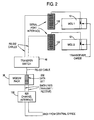
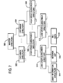
- FIG. 2 illustrates in more detail the components that allow communication between the MCU 10 and a central office 30.
- Messages from the central office 30 are received by a conventional 829 channel interface available from Comfab of Addison, Illinois as Model DST4829BJ.
- This channel interface 100 is connected to a conventional 202 data set modem available from Halmark of Billerica, Mass as model RM16M20255.
- the modem 38 is connected to a transfer switch 48 available from Data Probe of Englewood, New Jersey as Model KAB232R.
- the transfer switch 48 will be activated by the backup MCU 12 to transfer message traffic to the backup MCU 12 whenever the backup MCU 12 detects that the primary MCU 10 is malfunctioning. The method of determining whether a transfer should occur will be discussed in more detail hereinafter.
- the transfer switch 48 is connected to the primary 10 and backup 12 MCUs by conventional serial port interfaces 102.
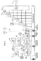
- FIG. 3 illustrates in more detail the connection arrangement between the VPUs and the digital switch 14.
- a suitable digital switching system with a 1536 by 1536 channel capacity is available from Excel, Inc. of Sagamore Beach, Mass.
- Each VPU includes the components as illustrated in FIG. 4.
- Each VPU is essentially an IBM AT type computer with special communications cards mounted on the backplane.
- the CPU 200 is based on the Intel 80386 processor and an appropriate unit is available from Sigma Design of Fremont, California as Model No. CPA3820BACX.
- the CPU 200 stores temporary data structures and messages, as well as the VPU control programs that are executing, in a memory unit 202 configured for 8 megabytes of random access memory.
- a suitable memory unit 202 is available from Sigma Design of Fremont, California as Model CMA380K00N while the memory chips for the unit can be obtained from Centon of Wilmington, Mass.
- the CPU 200 has direct access to the memory 202 via a conventional 32 channel bus. Messages are stored on two hard disk drives 204 and 206.
- the hard disk drives each having a 760 megabyte storage capability, can store the same messages and other information using a technique conventionally called mirror image storage. This operation is controlled by the disk controller 208.
- the hard drives 204 and 206 are available from Anthem of Wilmington, Mass. as Maxtor Model No. XT8760E while the disk controller is available from DPT of Maitland, Florida as Model PM301/75.
- a floppy disk drive 210 which is preferably a Fujitsu Model M2553K03A is used for loading the system initially and for any maintenance modifications that need to be performed.
- the MCU 10 and other VPUs are connected to the VPU of FIG. 4 through a conventional Ethernet internal communications link 212 which is available from Excelan of Nashaua, New Hampshire as Model No.
- This internal communication link 212 can be either two physical Ethernets or a single Ethernet with two logical buses thereon. If two physical Ethernets are used, two internal communication link units 212 must be provided.
- the communication between the CPU of the VPU and the DSS 14 is through digital ports 214 to a conventional T1 interface 216 and thereafter to the DSS 14, and this interface 216 is available from Dialogic of Parsippany, New Jersey as Model No. T1DT1124.
- the port line cards 214 are also available from Dialogic as Model No. D41B.
- the port line cards perform a conventional digitizing technique known as ADPCM (Adaptive Delta Pulse Code Modulation) sampling at a rate of approximately 6,000 8-bit samples per second.
- ADPCM Adaptive Delta Pulse Code Modulation
- the digital compression performed using this method allows the CPU 200 to store only four bits of every 8 bit sample. This results in a storage requirement of only 3K bytes per second thereby increasing the capacity of the system.
- the line cards also have the internal capability of producing a beep, detecting a call and monitoring call progress, generating DTMF, detecting DTMF, generating MF, detecting MF, monitoring on and off hook conditions and going on-hook and off-hook.
- the application process interfaces to the line cards using linked library routines that make system calls to voice line card driver routines. Each line card has two 512 byte buffers that are alternately loaded and retrieved in ping pong fashion during call processing. The line card automatically takes care of filling and unloading the buffers over the line.
- the multi-IO unit 216 provides an interface for a video display whenever maintenance of the VPU is necessary.
- Each of the master control units 10 and 12 are essentially IBM AT based machines as previously discussed with respect to the VPUs of FIG. 4.
- This system includes a computer 300, memory 302 with at least 4 megabytes of random access memory, hard drives 304 and 306, floppy drive 310 controlled by disk controller 308 and an internal communication link 312 for the internal bus 28.
- the same component manufacturers and model numbers of the VPU are applicable to the corresponding components of the MCU.
- Each MCU additionally contains a conventional modem 314 which allows the system to be accessed by a dial-up access method for maintenance purposes.
- An appropriate modem is available from Western Microtechnology of Burlington, Mass. as U.S. Robotics Model No. 1-0021-00.
- the serial link provides serial connection to the digital switch 14, central office 30 and transfer switch 48.
- the serial link unit 316 is available from Arnet of Arlington, Tennessee as Model No. SP84BKUNITSW.
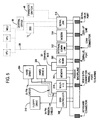
- the processes illustrated in FIG. 6 are executed by the various processing units previously discussed.
- the processes illustrated in FIG. 6 are represented using descriptive names and program acronyms.
- the master control process 400 has the acronym MOMD.
- the acronyms refer to the corresponding "C" programming language processes or assembler processes.
- the central office interface process 402 examines the message and places an appropriate message in the message buffer for the master control process 400.
- a call arrival (service request) packet arrives from the DSS 14 through DIP 404 to MCP 400.
- the MCP 400 coordinates the two packets (call arrival and SMDI) through the referenced channel in each packet. If MCP 400 receives an SMDI packet without receiving a call arrival packet within 12 seconds, it discards the SMDI packet. If MCP 400 gets a call arrival packet without an SMDI packet within 6 seconds, MCP 400 places the call on the least busy VPU without SMDI information.
- the master control process 400 determines how to route the call through the switch 14 and transmits that information to the DSS interface process 402 which provides an appropriate channel assignment to the DSS 14. This channel assignment is entered on a list in the MCU and includes port assignments for the VPUs. Based on the selection of the voice processing unit the master control process 400 provides a copy of the SMDI packet and the call routing information to a corresponding VPU interface process 406.
- Each interface process described herein essentially translates an information packet from one protocol to another protocol allowing processes with different message formats to interact.
- Each interface process also calls appropriate driver processes through library processes 401.
- the driver routines are conventional routines that can be obtained from the equipment manufacturer or produced by one of ordinary skill in the art.
- the VPU interface process 406 for each one of the VPUs is an individually spawned process of the master control process. This process is a connection oriented process or virtual link process rather than a packet oriented process. In a virtual link process, the process will terminate if the connection to the designated VPU fails. This process is automatically supported by the TCP/IP protocol executed by the processes provided by the net card manufacturers.
- MCP 400 is informed by the operating system and changes the status of the corresponding VPU from available to unavailable. The MCP 400 then periodically tries to restart the interface process as long as the system configuration information indicates the VPU should be online and active. When the interface process successfully executes, the VPU is back on line and the status is changed to available. An appropriate connection protocol and process is available from Excelan.
- the VPU interface process 406 translates buffer messages from the operating system format (Xenix) to the format of the Ethernet internal bus 28.
- the information is transmitted to the appropriate VPU 16 over the bus 28 to an MCU interface process 410 in the appropriate VPU.
- the routing of the messages to the appropriate VPU or MCU process is automatically handled by the TCP/IP protocol using, for example device or process addresses.
- the MCU interface process 410 translates the message into the operating system message format of the VPU and provides it to the VPU control process 412.
- An application process 414 when it detects an incoming call (a ring), requests that the VCP 412 provide a call information packet including the incoming port and the SMDI packet.
- the AP 414 When the AP 414 detects a ringing call, it asks VCP 412 if there is any SMDI packet waiting for a VPU port. If there is, VCP 412 forwards the packet. If not, AP 414 will wait for up to 5 seconds for a packet to arrive. If none arrives, it is handled the same as if no SMDI packet arrived from the central office 30.
- the VPU control process 412 then provides the message to the application process 414.
- the application process 414 can be a voice mail process or some other process used for message processing.
- the application process 414 controls the communication process with the subscriber or caller over the communication ports 214 through the DSS 14 and central office 30 using card driver and other library processes 413.
- MIP 410 add VIP 406 requests from the MCP 400 the subscriber information (a user information structure) which defines the characteristics of the subscribers mail box (greeting length, message length, options etc).
- the master control process 400 maintains a directory structure of such files as illustrated in FIG. 7 and which will be discussed in more detail later.
- the user information structure is obtained by MCP 400, it is transferred through the VIP 406, the MIP 410, the VCP 412 to the appropriate application process 414 and stored in a local cache.
- Several information structures can be stored in the cache at the same time.
- requests for information from the user information structure can be processed locally without accessing the internal bus.
- the cache for user information is a read only cache. Any requests for update are immediately written back. However, the updated information is kept in the cache. Up to five user information structure entries are cached and additional entries needed are not permitted. The cache is emptied at the end of the call. Any request that cannot be serviced by the cache is sent to the MCU.
- the application process 414 plays the appropriate greeting stored on the hard disk for the subscriber as a greeting file identified by the telephone number.
- the application process 414 then records and stores any message, as a message file on the hard disk.
- the application 414 asks VCP 412 for a post office entry in which to store voice data. AP 414 uses this file for message storage and later adds it to the message list for the subscriber.
- a message may be terminated due to several conditions: the caller hangs up, the caller pauses for a predetermined length of time, for example 8 seconds, the message has exceeded the message limit, or a DTMF is detected. If a DTMF signal has been received at the end of a message, call processing then continues allowing the caller to review the message mark it as urgent, etc.
- the application process 414 sends a location storage message to the MCP 400 which creates a message list in a format as illustrated in FIG. 8. When the line finally goes on hook, the application process 414 notifies MCP 400 that the call is finished. MCP 400 accesses the channel assignment list and issues a disconnect command to the DSS 14 for that assignment.
- the application process 414 also indicates whether the message waiting indicator should be turned on or if outdialing is necessary. If the indicator should be turned on, the MCP 404 prepares an appropriate MWI packet and provides it to the CIP 402 which provides the packet to the central office 30.
- the message file for the user includes message records which identify which VPU the message is located on, the file name for the message and whether the message is a new message and whether this is the end of a segmented message.
- the application process 414 obtains the subscriber information from the master control process 400, verifies the passcode and presents the options for message retrieval. Whenever the subscriber logs into the system, the message waiting indication is turned off. Also, any pending outdial requests to the subscriber are detected.
- the application 414 requests from MCP 400 the list of messages as illustrated in FIG. 8.
- the application process 414 will then create a doubly linked list as illustrated in FIG. 9. The doubly linked list is used by the application process to index through the messages as the user desires.
- AP 414 would connect to VIP 424 over the internal bus 28.
- This connection is a request for remote voice data and part of the request is which voice data file is needed. Voice data is sent over the connection in 8k byte segments.
- the remote voice data is cached on the local drive.
- the AP 414 is receiving the data, it is played to the caller. The transfer of data is continued until either the message is played to completion or the message is terminated due to DTMF being received. If the message is terminated before it is complete, the message is removed from the local cache. Entries remain in the local cache as long as they are accessed within a predetermined amount of time, for example 24 hours.
- VTP 424 will not respond to the message transfer request and the application process plays a message to the subscriber that the message is not currently available.
- application process 414 provides the third message 703 to the subscriber off the local hard drive.
- the application process 414 After call disconnection, frees up local storage by deleting any message files to be deleted from the local directory, sends a delete message through MCP 400 to the VCP 412 storing any remote messages to be deleted and sends a message to MCP 400 specifying the remaining messages that need to be removed from the message list. MCP 400 proceeds to remove the messages from the list. When the subscriber finally goes on hook, the application communicates this to the master control process 400. The MCP 400 through DIP 400 instructs the DSS 14 to disconnect the call routing.
- Any message stored in the system can cause outdial notification to be performed and depends on the configuration parameters for the subscriber. If outdial notification needs to be performed, the application 414 issues an outdial request through the appropriate processes to the outdial process 426. ODP 426 maintains a list of pending outdial requests and when they need to be performed.
- the MCP can schedule the request to be performed by the VPU which contains the original message. MCP 400 could issue a request of DSS 14 to connect an outgoing line to the appropriate VPU port. MCP 400 would forward the outdial request through VCP 412 to AP 414 to service the request. The MCP 400 also requests that the VPU storing the message start the application process 414 corresponding to the VPU port designated.
- the application process 414 will examine the port for a dial tone, if a dial tone does not exist the application process will go on hook, the outdial will be aborted and ODP 426 will be informed and the application process 414 will handle the incoming call. The ODP 426 will then reissue the request.
- the application will dial the number specified in the outdial file. If the dialed station does not reply within a certain length of time, for example four rings it reaches a busy line, the attempt is terminated and rescheduled. If the dialed station answers and if the outdial message is to a pager system, the appropriate pager tones are played.
- a greeting message is played indicating a message is awaiting delivery and asking for the passcode. If the correct passcode is given the message is played as previously described. The pending requests are deleted as soon as the subscriber enters the passcode as previously discussed.
- the application 414 performed a pager type message sending operation, the message is maintained on the outdial process message list until the subscriber calls in and gets the message. If the message remains on the list longer than a certain length of time, for example fifteen minutes, the pager will be beeped again. This will continue until the pager has been beeped a predetermined number of times.
- application process 414 Whenever a caller inputs a message into the system that should be distributed to a limited set of the subscribers (a group message), application process 414, in addition to sending the location of the message to the master control process 400 to create an appropriate mailbox message list entry, causes the master control process 400 to activate the distribution process 428.
- the distribution process 428 proceeds to access the group of designated mailboxes in the system and create a message entry for each subscriber referencing the location of the group message. Appropriate message waiting indicator messages are also sent to the central office 30.
- the MCP 400 provides the appropriate list to the application process 414.
- a broadcast message When a message is to be sent to all subscribers, it is called a broadcast message.
- a broadcast message When a broadcast message is created the message is listed in a single system wide broadcast mailbox based on a menu selection by a subscriber. This type of message does not create a message waiting message indicator for the central office 30.
- the application process 414 checks the broadcast mailbox. If a broadcast message exists it is added to the subscribers message list during the log-in process by the voice application.
- the master control process 430 in the hot standby MCU 12 executes all of the processes that the master control process 400 in the primary MCU 10 executes, so that the master control process 430 is ready to take over processing when the MCU 10 fails. This is accomplished by the master control process 400 sending all requests from processes to the master control process 430 through the master control interface process 432. The process 430 then performs appropriate processing with the corresponding interface processes inactivated. During operation, the poll process 436 periodically sends poll requests over the virtual link to the MCU 10. The MCP 400 determines whether each VPU is operating by determining whether a request from the VPU is received every two minutes. The master control process 430 in the hot standby MCU 12 also periodically checks on the operating state of the primary master control unit 10.
- the master control process 430 requesting that the master control process 400 respond to a poll request every thirty seconds. If the master control process 400 does not respond within a predetermined time period, for example, 30 seconds, the master control process 430 requests that the VPUs 16-24 confirm that the primary MCU 10 is malfunctioning.
- the master control unit 12 places a broadcast message on the internal bus 28 using a message protocol, such as UDP available from Excelan. The message is processed by the master control unit check process 434 of each VPU.
- the master control unit check process 434 requests that the VCP 412 poll the MCP and if a reply is not received with 10 seconds the virtual link is considered broken.
- the MCU interface process is a connect oriented process rather than a message oriented process and if the connection between the corresponding VPU interface process 406 and the MCU interface process 410 has failed this polling request will recognize this condition.
- the process 434 responds to the broadcast request of the master control process 430, based on the response to the VCP 412 poll, indicating whether the connection between the VPU and MCU 10 is active. If the master control process 430 receives one indication from any VPU that the primary MCU 10 is functioning properly, the master control process 430 in the hot standby MCU 12 will not take over operation and will try to reestablish a virtual connection to the MCU 10. If the primary MCU 10 has failed each of the MIP processes 410 in the VPUs have also failed.
- MIP 410 When MCUP 434 asks VCP 412 to test the link, if MIP 410 has terminated because of a failed link, MIP 410 will restart and place a message on the bus 28 every ten seconds requesting that the active MCU respond indicating that it is in control. The other VPUs perform the same operation.
- the hot standby master control process 430 when taking over the operation of the failed MCU activates its VPU interface processes 406-408 which respond to the requests by the MIPs 410 indicating that the hot standby 12 has taken control.
- the process 430 also activates the standby CIP 402 process. The activation of this process causes switch 48 to switch to send data to the MCU 12.
- DIP 404 is also started.
- the hot standby 12 then becomes the primary. When the MCU 10 comes back on line, it determines that the hot standby unit 12 is active and controlling, and converts itself into a hot standby unit.
- the MCUs each load the system configuration table designating whether each MCU is a primary and also indicating how many VPUs are configured in the system.
- the primary 10 and standby 12 MCU's immediately begin to try and establish a link virtual between the standby master control process 430 and MIP 432 and MCP 400. The attempt to establish the link will continue for a predetermined time, for example 5 minutes.
- the VPU's also start up but do not know which MCU is the primary. As a result, VCP 412 and MIP 410 begin broadcasting messages on the bus 28 requesting connection to the primary MCU 10.
- the MCU 12 will start its interface processes and respond to the broadcast messages of the VPUs, thereby taking over as the primary. If the configured primary MCU 10 later comes on line it queries the other MCU and determines that it is running as primary and then configures itself as the list standby.
- the master directory 500 has listed therein exchange directories 502 and 504 for each exchange authorized in the system. In a telephone number, excluding the area code, the first three digits of the telephone number are the exchange number. Each exchange directory includes plural high order subscriber directories 506 and 508. The next two digits in the telephone number after the exchange are used to select a high order directory within the high order directory list of the exchange directory. The final two digits are used within the high order directory to select among plural low order subscriber directories 510 and 512.
- the low order subscriber directory lists files for each subscriber in the system corresponding to the low order digits, the last two digits, in the telephone number.
- the lower order subscriber directory lists a user information structure file 514 which stores the information necessary to process a call for a subscriber, a message file 516 which lists the locations of the messages for the user and a bill data file 518 which lists the name and address of the subscriber. If for example the user's telephone number was 555-1122 the 555 exchange directory would be selected from the list in the master directory, the 11 high order subscriber directory would be selected from the exchange directory list and the 22 low order subscriber directory would be selected within the 11 high order directory list.
- the user information structure file 514 for the subscriber or the message list file 516 for the subscriber would be selected as appropriate.
- the mailbox process 418 services requests for creation, deletion and reinitialization of subscribers. This process creates or removes the subscriber directories and asks for mail box data from MCP 414. Requests for the services provided by this process typically come from an administration program, however, the subscriber, through the application process 414 can request this service.
- call switching can be performed.
- a way in which call switching can be performed is to have the master control process execute the MCU save-resume process 420 which sends a packet over the data bus 28 which causes the VPU save and resume process 422 to be executed.
- the VPU save-resume process 402 can save the state of the application process 414 and transfer it to VPU 24.
- the save-resume process 402 executing on VPU 16 transfers all of the current state to VPU 24.
- This state includes all pertinent data structures such as the doubly linked list in Fig. 9 and the stack from the application process 414 which contains among other things the thread of execution and values of parameters which are passed between subroutines in the application process 414.
- the master control process 400 causes the appropriate connections to be made in the digital switch 14. This allows the application process in the VPU 16 to handle another call or application while the other VPU 24 continues call processing where the VPU 16 left off. The caller is completely unaware that the call has been shifted from one call 'processing unit to another.
Abstract
Description
- The present invention is directed to a telephone communication system used for handling information such as messages, typically voice mail messages, and, more particularly, is directed to a system that provides a tightly coupled distributed architecture that allows substantially increased efficiency of equipment utilization, increased subscriber capability, modular expansion capability and low access blockage for subscribers and non-subscribers.
- Typical voice mail systems are designed for operation in conjunction with a private business exchange (PBX). The typical systems include one or more separate call processing computers dedicated to serving a predetermined set of PBX lines and subscribers. Each processor stores the subscriber information for the subscribers assigned to that processor. The processors store messages in a common storage accessed over dedicated storage buses. Each call processor acts independently and competes for access to the common storage. Because each call processor serves a predetermined set of lines, when a message originator, whether a subscriber or non-subscriber, calls a subscriber and wishes to leave a voice message, if the lines dedicated to the subscriber are busy or if the call processing computer is unavailable for any other reason, the message originator is not allowed to leave a message. A processor does not have access to the subscriber information stored in another processor, thereby preventing other processors from handling the call. In like manner, if a subscriber wants to obtain his messages and the limited number of lines to the subscriber's dedicated call processing computer are busy or the processor is unavailable, the subscriber cannot get his messages. A prior art system as described above is typified by the system described in U.S. Patent 4,371,752.
- EP-A-0237834 shows a typical prior art example of a front end switch-based message processing system. More particularly, it shows a system wherein multiple service assemblies B1...Bn are connected to outputs of a switch VE, the switch VE functions under control of a separate computer system VA, and wherein incoming calls are specifically routed to a previously assigned service assembly Bi where i=1...n for the provision of a desired call service such as voice messaging and the like. In this matter, incoming calls are processed by previously assigned and mapped service assemblies.
- US-A-4400587 shows a method of overflow and diversion re-routing for use in an automatic call distributor system of the type in which an incoming call is assigned to an original gate (i.e. a group of human agents) but in selected circumstances the call is to be re-routed to an alternative gate. Re-routing occurs either by directing an incoming call to a previously assigned and stored first choice network number or to a previously assigned and stored alternate network number.
- In accordance with one aspect of the present invention, a message communication system comprises at least first and second message processing means for processing a message by storing and/or playing the message; and switching and control means for dynamically selecting an available one of the message processing means based on availability factors to process the message and routing the message to and/or from the selected message processing means.
- In accordance with a second aspect of the present invention, a message processing method using a switching system and at least first and second message processing units connected to the switching system, comprises the steps of:
- a) dynamically selecting one of the message processing units based on availability factors for processing a message;
- b) controlling the switching system (14) to route the message to the selected message processing unit; and
- c) processing the call by the selected message processing unit by storing and/or playing the message.
- The present invention allows calls to be processed as long as any message processing unit is available.
- The present invention allows any message processing unit to handle any incoming line and any subscriber. In some examples a message can be temporarily stored in different positions of the system to improve performance. The invention may be arranged to allow the system to store and retrieve any message no matter where stored in the system. A message may be permanently stored only once.
- The present invention enables subscriber information to be stored in a manner allowing any message processing unit to have access to that information to process the message and can prevent storage access bottlenecks.
- The invention can be scaled to very large sizes to handle information traffic for cities, states national and world subscriber sets.
- The present invention can provide a distributed architecture that prevents line blockage and prevents storage blockage.
- The system can handle both voice and data traffic.
- The present invention can provide maximum availability of message processing units by freeing a voice processing unit to handle another call while the voice processing unit storing the message serves the subscriber with respect to that message. For example, the invention can increase the equipment utilization efficiency by algorithmically distributing calls to processing units and can allow access to any message through any voice port.
- The present invention can dynamically locate stored messages by algorithmically distributing messages among call processing units.
- In one example a voice processing unit (VPU) is designated as a home voice processing unit for a subscriber's message. An incoming call or an access by a subscriber from a central office can be switched to the home VPU by a digital switching system (DSS) under the control of a master control unit (MCU). If the master control unit determines that all lines to the home voice processing unit are busy or the home voice processing unit is otherwise unavailable, the master control unit causes the digital switching system to switch the call to another or remote voice processing unit. The remote voice processing unit then handles the call by either locally storing a message or retrieving a message from the home voice processing unit storage or elsewhere in the system over an internal network. If a message is stored remotely and the home voice processing unit is processing a subscriber request, the home voice processing unit can access the remote message over the internal network or the master control unit can switch the call routing through the digital switching system to the remote voice processing unit for processing of the remote message by the remote processing unit. Once the remote message is processed the master control unit can return the digital switching system routing to the home voice processing unit or to another voice processing unit allowing the home voice processing unit or the other processing unit to continue processing messages stored in the home unit or in any other voice processing unit. Each voice processing unit stores both remote and home messages locally on local disc storage units. The master control unit can store subscriber related information such as the identification of the home voice processing unit for each subscriber and the location of each message for that subscriber. Communication between the master control unit and the voice processing units, and among the voice processing units is over the internal network. If out-dialing of the message is necessary, such as when a pager needs to be activated, the master control unit connects the voice processing unit storing the message, whether the home or remote unit, to the central office through the digital switch and the unit places the desired call. A hot standby master control unit is provided to take control of the system in the event that the primary master control unit fails.
- These together with other objects and advantages which will be subsequently apparent, reside in the details of the construction and operation as more fully hereinafter described and claimed, reference being had to the accompanying drawings forming a part hereof, wherein like numerals refer to like parts throughout.
-
- FIG. 1 illustrates the components of a system in accordance with the present invention;
- FIG. 2 illustrates in more detail the connection between the central office and the master control unit;
- FIG. 3 depicts the connection of the voice processing units to the digital switching system;
- FIG. 4 shows the components of each voice processing unit;
- FIG. 5 shows the components of each master control unit;
- FIG. 6 illustrates the processes executed and the flow of voice messages and data;
- FIG. 7 illustrates the directory structure of files associated with a subscriber;
- FIG. 8 depicts how messages are stored; and
- FIG. 9 shows a doubly linked list used to output messages to the subscriber.
- The present invention is specifically designed for use with a telephone company central office or for a very large corporate user, however, an exchange such as private business exchange can take advantage of the high availability characteristics of the present invention in situations where high voice traffic exists, such as telephone shopping. The distributed architecture allows the system to be configured presently for up to 1536 voice channels, approximately 100,000 mailboxes and over 7,000 hours of voice storage. The architecture allows the present invention to simultaneously run multiple applications while keeping the underlying system totally transparent to the end user. The caller and/or subscriber can send, reply to or redirect messages at will irrespective of which processing unit stores particular messages or which processing unit is handling the call. The various computer programs executed within the distributed architecture are preferably written in the "C" programming language or Intel 386 assembly language and an appendix of the programs executed by the various processors within the distributed architecture is included herewith. Each processor in the distributed architecture is preferably using an operating system such as Xenix or Unix System V which allows multiple real time tasks.
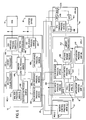
- The
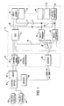
system 6 of the present invention, as illustrated in FIG. 1, includes both primary 10 and standby 12 master control units (MCU) which control switching by a digital switching system (DSS) 14. The MCU 10 coordinates the routing of calls, based on conventional Simplified Message Desk Interface (SMDI) information packets from acentral office 30, through the DSS 14 to voice processing units 16-24. Up to 64 voice processing units can be provided in the system where each voice processing unit has a T1 termination for up to 24voice ports 26 and is capable of storing up to 110 hours of voice storage for approximately 2,200 mailboxes. - Assignment of an incoming call by the MCU 10 to a VPU occurs over an internal bus or
network 28 that includes both a data bus and a voice bus. Thisbus 28 rather than being a traditional bus can be a network of any topology such as a star or token ring. Control data and messages between theMCU 10 and VPUs or between the VPUs is routed over the data bus of theinternal bus 28 while the voice messages are routed between the VPUs over the voice bus of theinternal data bus 28. It is preferred that theinternal bus 28 be a standard bus such as is provided by an Ethernet. The voice and data logical buses can be implemented as a single physical bus over the Ethernet or as separate Ethernets when interprocessor voice or data communication is high. - It is preferred that the
digital switching system 14 be connected to acentral office 30 through a multi-line hunt group (MLHG) 32. It is also preferred that a digital central office be used so that digital voice samples are passed between thecentral office 30 and theDSS 14. However, if the central office is an older switch such as an AT&T 1A-ESS, achannel bank 34 can optionally be provided in the optional telephonenetwork interface circuitry 8 for converting incoming analog signals to digital packets. Communication between theMCU 10 and thecentral office 30 is optionally via conventionalserial modems - During operation when a subscriber or non-subscriber at a calling
station 40 calls a subscriber at a calledstation 42, the call is switched normally through thecentral office 30 whereby a ringing signal is sent to the calledstation 42 and a ring back tone is returned to the callingstation 40. After a predetermined number of rings (for example 5) or immediately if the line is busy, the call is forwarded to themulti-line hunt group 32 by thecentral office 30. When thecentral office 30 determines that a line is available, thecentral office 30 causes thegroup 32 to ring one of the ports on theDSS 14. If a line is available to theDSS 14, normally a message packet, preferably in SMDI format, is sent from the message desk of thecentral office 30 to MCU 10 optionally throughmodems central office 30, after transmitting the SMDI packet, places the call on the designated port of theDSS 14.DSS 14, when it detects a call, informs theMCU 10 of a call arrival indicating on which port the call has arrived. TheMCU 10, if a packet arrives prior to a call at theDSS 14, waits for a predetermined time, for example 12 seconds, and if the call does not arrive at theDSS 14, discards the packet. If a call arrives at theDSS 14 without the packet arriving within 6 seconds, a non-typical situation, the call is assigned to the first available VPU and theDSS 14 is switched accordingly. The VPU makes the request for the mailbox number, receives the number from the caller and provides the number to theMCU 10 in a phoney SMDI packet. If a matching SMDI packet and call port on theDSS 14 arrive, or after a telephone number has been entered, then theMCU 10 accesses the mailbox database and determines which VPU 16-24 is thehome VPU 16 and, if thehome VPU 16 is available. TheMCU 10 instructs theDSS 14 over alink 44 to route the call to thehome VPU 16. A conventional T1 channel (time slot) to channel (time slot) connection command is provided to theDSS 14 from theMCU 10 to effect the routing desired. - In a situation where, for example, a cellular telephone switch is being serviced and in-band signalling (DTMF, MF or others) is required, the
central office 30 andDSS 14 have a dedicated connection through to a VPU awaiting the in-band signals. When the in-band signals have been received designating the called number, switching of the call to the home VPU, as described above when an SMDI packet is not received and must be entered manually by the caller, is performed. - After the call is switched, the
home VPU 16 obtains the relevant subscriber information (including a greeting storage location) from theMCU 10 and then can play a system greeting or a personal greeting recorded by the mailbox owner back through theDSS 14,channel bank 30 andcentral office 30 to the callingstation 40. The homevoice processing unit 16 then plays a beep signal to the caller indicating that the caller can begin recording a message. Recording stops when the caller hangs up, presses a touch tone key or is silent for a message time out period. The caller can then review, record or send a message or select send options such as marking the message urgent or confidential. After the caller sends the message theVPU 16 stores the message as a file in theVPU 16 and communicates the location of the message back to theMCU 10 which stores the location of the message in the subscriber's message list mailbox file located in theMCU 10. TheMCU 10 then disconnects the routing inDSS 14 and sends any necessary message waiting information to thecentral office 30. - The above discussion assumed that the home VPU was available, had adequate storage for storing the message and had available call processing ports. When these conditions are satisfied, there is a strong preference, no matter the type of routing algorithm used, for selecting the "home" VPU. If one of the above factors is not correct the call can be routed to a
remote VPU 24. This routing to theremote VPU 24, called call switching, also depends on the current switching load on theDSS 14. If the switching load on theDSS 14 is high, for example 99% of capacity, call switching could be prevented. It is possible to route or switch the call to the least busy VPU or the first VPU available on a list with a predetermined order of VPU selections. - As another alternative a more complicated routing determination can be dynamically made using an algorithm which compares all VPUs. Prior to selecting the VPU to handle the call, the
MCU 10 can execute a call routing algorithm which determines whether thehome VPU 16 or aremote VPU 24 should be selected. First theMCU 10 executes a call placement equation, as set forth below, for each VPU 16-24 that has available ports and available storage to determine which VPU should receive the call:
- If the selection algorithm determines that a call should be routed to the
remote VPU 24, at the beginning of the call, because the subscriber information structure indicates the greeting is stored onVPU 16, theremote VPU 24 obtains the personal greeting of the subscriber from thehome VPU 16 over theinternal bus 28 and then plays that personal greeting to the callingstation 40 through theDSS 14. Theremote VPU 24 would then record the caller's message locally in theremote VPU 24 providing the same review and re-record features previously mentioned. When the call is finished theremote VPU 24 would inform theMCU 10 that the subscriber has a message stored on aremote VPU 24. TheMCU 10 would place the location of the message in the subscriber's message list file. - The system has the capability of informing a subscriber that he has new messages by communicating to the
central office 30 using a standard Message Waiting Indication (MWI) packet over SMDI. The central office should produce a stutter dial tone the next time the subscriber picks up the phone at the calledstation 42 or light a light on the calledstation 42. The subscriber desiring to obtain his messages would then call their own telephone number (which would result in forwarding to the voice mail system) or dial a local access number in thecentral office 30 for thevoice mail system 6. If the caller dials their own number, theMCU 10 could perform the routing algorithm previously mentioned to determine which VPU should handle the call. If a system access number is used the subscriber is routed directly to an appropriate VPU which requests the user enter the mailbox number (their own telephone number) and theMCU 10 once again can perform the call routing algorithm. - If the VPU selected is the
home VPU 16, it will play the locally stored personal greeting of the subscriber to the subscriber. If the VPU selected is aremote VPU 24, the remote obtains the greeting from thehome VPU 16 as previously described and plays it to the subscriber. If thehome VPU 16 does not respond to the request for the greeting message, the system greeting is played to the subscriber. This generally indicates to the subscriber that all messages are not available because the home VPU is down. However, because the greeting and log-in procedures take time during which the home VPU could become available and if the system has the alternate call switching capability, the subscriber should continue until the system indicates all messages are not available. - When the subscriber presses the appropriate log-in digit at the calling station, whether the subscriber is at the previously called
station 42 or at another location, the subscriber is prompted to enter an appropriate passcode. The subscriber is then led through a series of typical prompts to listen to messages, send messages, etc. If the subscriber wishes to receive his messages, the system will play the messages to the subscriber no matter where the messages are stored. - If the
home VPU 16 is selected by theMCU 10 and messages are to be played to the subscriber, thehome VPU 16 obtains and examines the list of messages from theMCU 10. If all the messages are on thehome VPU 16, thehome VPU 16 plays the messages to the subscriber through theDSS 14 and thecentral office 30. If upon examining the list, as the messages are sent to the subscriber, if at least one message is indicated as being stored on theremote VPU 24, theremote VPU 24 obtains the message over thebus 28. - As an alternative the
remote VPU 24 can send a message to theMCU 10 indicating that a remote message needs to be processed. TheMCU 10, based on the availability of theremote VPU 24 and the load on thehome VPU 16 can indicate to thehome VPU 16 that thehome VPU 16 or theremote VPU 24 should process the message. In this alternative theMCU 10 can also communicate back to the home VPU indicating whether the home VPU should obtain the message overbus 28 or whether the processing for this message should be switched to theremote VPU 24. The first option, in which thehome VPU 16 continues processing, operates in a manner similar to the way that the home personal greeting was played to a non-subscriber by aremote VPU 24. In this situation the home VPU requests over theinternal bus 28 that theremote VPU 24 send the remote message to thehome VPU 16. Thehome VPU 16 stores the message locally and then plays that message to the subscriber. This first option would normally be chosen when the remote has all 24 ports busy or is ranked very low in the selection list computed, using the call placement algorithm at the time the remote message is encountered. If the second option in the alternate system is selected by theMCU 10 and processing is to be switched, the state of thehome VPU 16 during the subscriber's call is transferred over thebus 28 to theremote VPU 24. At the same time the MCU instructs the DSS to route the call to the remote 24. Theremote VPU 24 then continues call processing by providing the message to the subscriber through the reconfiguredDSS 14 and thecentral office 30. - When the remote message processing is completed, if the subscriber wishes to continue call processing and if it is available, control can be transferred back to the
home VPU 16 by sending the state of theremote VPU 16, as to the subscriber's call progress, back to thehome VPU 16 over thebus 28 and theMCU 10 switches theDSS 14 back to the original connection arrangement. If thehome VPU 16 is not available, the messages are obtained over thebus 28 and provided to the subscriber by theremote VPU 24 until thehome VPU 16 becomes available. - In a situation where a
remote VPU 24 is selected for the subscriber call processing, the selection could have been made because thehome VPU 16 was unavailable. When all of the messages for the subscriber are stored on the home VPU, theremote VPU 24 andMCU 10, in call switching, will attempt to transfer control to thehome VPU 16 for each message. During this operation theremote VPU 24, after receiving the message list from theMCU 10, upon examining the first message will indicate to theMCU 10 that a transfer is requested. If theMCU 10 responds with a transfer command, a transfer as previously discussed will occur. If theMCU 10 responds indicating that theremote VPU 24 should process the message, the message is obtained from thehome VPU 16 over thebus 28. By having the remote VPU attempt a transfer for each message if thehome VPU 16 becomes available, in accordance with the call routing calculations previously discussed, theremote VPU 24 will transfer call processing to thehome VPU 16. - If the
remote VPU 24 is examining the list of messages and encounters a message stored in its own storage theremote VPU 24 will play the message to the subscriber as previously discussed. If theremote VPU 24 encounters a message storage record indicating that a message is stored on anotherremote VPU 20, theremote VPU 24 will attempt to transfer to the otherremote VPU 20 on which the message is stored. - The present invention has the capability of immediately sending the message to the subscriber if this feature is selected by the subscriber. This can apply to all messages or to some subset such as urgent ones. In this situation, the voice processing unit whether it is the
remote processing unit 24 or thehome processing unit 16 sends a message to theMCU 10 indicating that out-dialing must be effected. TheMCU 10 examines the state of theDSS 14 to determine which lines to thecentral office 30 are available, examines the status of the VPU storing the message to determine whether a port is available on the VPU storing the message to be sent and examines the status of the other VPUs. The MCU selects an available line (channel) through theDSS 14 and sends that selection to the VPU, either remote 24 orhome 16 depending on where the message is stored. The VPU examines the selected line to determine whether a call has arrived from thecentral office 30 using conventional "glare" detection techniques in which the VPU listens for a dial tone on the line to determine if a dial tone is available. If "glare"' is detected (for example, no dial tone) the VPU indicates such to theMCU 10 and theMCU 10 selects another line in theDSS 14 and passes the selection information to the VPU. When an available outgoing line is detected by the VPU, the VPU proceeds to dial the number indicated in the subscriber's database for the urgent message. When an off-hook condition is detected at the number dialed, the VPU, as in the previous process, requests that the subscriber enter an appropriate passcode before the message is played. If the correct passcode is entered, the VPU allows the subscriber to log-in and then the VPU plays the out-dial message through theDSS 14 and thecentral office 30 if requested. - During this process, the
MCU 10 selects the VPU which will place the out-dialed call taking into consideration where the out-dialed message is stored. If the VPU storing the message is available and has sufficient ports, it is selected, otherwise a remote VPU is selected. A remote VPU either obtains the message from the storing VPU over thebus 28 or switches the VPU to the storing VPU once the connection is established using the same procedures discussed previously. This out-dial process will also access devices other than telephones, such as pagers, for message delivery. The processes that are executed by the MCU and VPUs during the above discussed operations will be discussed in more detail with respect to FIGS. 6-9. - FIG. 2 illustrates in more detail the components that allow communication between the
MCU 10 and acentral office 30. Messages from thecentral office 30 are received by a conventional 829 channel interface available from Comfab of Addison, Illinois as Model DST4829BJ. Thischannel interface 100 is connected to a conventional 202 data set modem available from Halmark of Billerica, Mass as model RM16M20255. Themodem 38 is connected to atransfer switch 48 available from Data Probe of Englewood, New Jersey as Model KAB232R. Thetransfer switch 48 will be activated by thebackup MCU 12 to transfer message traffic to thebackup MCU 12 whenever thebackup MCU 12 detects that theprimary MCU 10 is malfunctioning. The method of determining whether a transfer should occur will be discussed in more detail hereinafter. Thetransfer switch 48 is connected to the primary 10 andbackup 12 MCUs by conventional serial port interfaces 102. - FIG. 3 illustrates in more detail the connection arrangement between the VPUs and the
digital switch 14. A suitable digital switching system with a 1536 by 1536 channel capacity is available from Excel, Inc. of Sagamore Beach, Mass. - Each VPU includes the components as illustrated in FIG. 4. Each VPU is essentially an IBM AT type computer with special communications cards mounted on the backplane. The
CPU 200 is based on theIntel 80386 processor and an appropriate unit is available from Sigma Design of Fremont, California as Model No. CPA3820BACX. TheCPU 200 stores temporary data structures and messages, as well as the VPU control programs that are executing, in amemory unit 202 configured for 8 megabytes of random access memory. Asuitable memory unit 202 is available from Sigma Design of Fremont, California as Model CMA380K00N while the memory chips for the unit can be obtained from Centon of Wilmington, Mass. TheCPU 200 has direct access to thememory 202 via a conventional 32 channel bus. Messages are stored on twohard disk drives disk controller 208. Thehard drives floppy disk drive 210, which is preferably a Fujitsu Model M2553K03A is used for loading the system initially and for any maintenance modifications that need to be performed. TheMCU 10 and other VPUs are connected to the VPU of FIG. 4 through a conventional Ethernet internal communications link 212 which is available from Excelan of Nashaua, New Hampshire as Model No. 9900615-01. Thisinternal communication link 212 can be either two physical Ethernets or a single Ethernet with two logical buses thereon. If two physical Ethernets are used, two internalcommunication link units 212 must be provided. The communication between the CPU of the VPU and theDSS 14 is throughdigital ports 214 to aconventional T1 interface 216 and thereafter to theDSS 14, and thisinterface 216 is available from Dialogic of Parsippany, New Jersey as Model No. T1DT1124. Theport line cards 214 are also available from Dialogic as Model No. D41B. The port line cards perform a conventional digitizing technique known as ADPCM (Adaptive Delta Pulse Code Modulation) sampling at a rate of approximately 6,000 8-bit samples per second. The digital compression performed using this method allows theCPU 200 to store only four bits of every 8 bit sample. This results in a storage requirement of only 3K bytes per second thereby increasing the capacity of the system. The line cards also have the internal capability of producing a beep, detecting a call and monitoring call progress, generating DTMF, detecting DTMF, generating MF, detecting MF, monitoring on and off hook conditions and going on-hook and off-hook. However, the application process interfaces to the line cards using linked library routines that make system calls to voice line card driver routines. Each line card has two 512 byte buffers that are alternately loaded and retrieved in ping pong fashion during call processing. The line card automatically takes care of filling and unloading the buffers over the line. Themulti-IO unit 216 provides an interface for a video display whenever maintenance of the VPU is necessary. - Each of the
master control units computer 300,memory 302 with at least 4 megabytes of random access memory,hard drives floppy drive 310 controlled bydisk controller 308 and aninternal communication link 312 for theinternal bus 28. The same component manufacturers and model numbers of the VPU are applicable to the corresponding components of the MCU. Each MCU additionally contains aconventional modem 314 which allows the system to be accessed by a dial-up access method for maintenance purposes. An appropriate modem is available from Western Microtechnology of Burlington, Mass. as U.S. Robotics Model No. 1-0021-00. The serial link provides serial connection to thedigital switch 14,central office 30 andtransfer switch 48. Theserial link unit 316 is available from Arnet of Nashville, Tennessee as Model No. SP84BKUNITSW. - During call processing the processes illustrated in FIG. 6 are executed by the various processing units previously discussed. The processes illustrated in FIG. 6 are represented using descriptive names and program acronyms. For example the
master control process 400 has the acronym MOMD. The acronyms refer to the corresponding "C" programming language processes or assembler processes. - When SMDI information from the central office arrives over one of the eight RS232-1200 baud central office lines, the central
office interface process 402 examines the message and places an appropriate message in the message buffer for themaster control process 400. At the same time, a call arrival (service request) packet arrives from theDSS 14 throughDIP 404 toMCP 400. TheMCP 400 coordinates the two packets (call arrival and SMDI) through the referenced channel in each packet. IfMCP 400 receives an SMDI packet without receiving a call arrival packet within 12 seconds, it discards the SMDI packet. IfMCP 400 gets a call arrival packet without an SMDI packet within 6 seconds,MCP 400 places the call on the least busy VPU without SMDI information. - The
master control process 400, as previously discussed, determines how to route the call through theswitch 14 and transmits that information to theDSS interface process 402 which provides an appropriate channel assignment to theDSS 14. This channel assignment is entered on a list in the MCU and includes port assignments for the VPUs. Based on the selection of the voice processing unit themaster control process 400 provides a copy of the SMDI packet and the call routing information to a correspondingVPU interface process 406. - Each interface process described herein essentially translates an information packet from one protocol to another protocol allowing processes with different message formats to interact. Each interface process also calls appropriate driver processes through library processes 401. The driver routines are conventional routines that can be obtained from the equipment manufacturer or produced by one of ordinary skill in the art. The
VPU interface process 406 for each one of the VPUs is an individually spawned process of the master control process. This process is a connection oriented process or virtual link process rather than a packet oriented process. In a virtual link process, the process will terminate if the connection to the designated VPU fails. This process is automatically supported by the TCP/IP protocol executed by the processes provided by the net card manufacturers. If an interface process terminates,MCP 400 is informed by the operating system and changes the status of the corresponding VPU from available to unavailable. TheMCP 400 then periodically tries to restart the interface process as long as the system configuration information indicates the VPU should be online and active. When the interface process successfully executes, the VPU is back on line and the status is changed to available. An appropriate connection protocol and process is available from Excelan. - The
VPU interface process 406 translates buffer messages from the operating system format (Xenix) to the format of the Ethernetinternal bus 28. The information is transmitted to theappropriate VPU 16 over thebus 28 to anMCU interface process 410 in the appropriate VPU. The routing of the messages to the appropriate VPU or MCU process is automatically handled by the TCP/IP protocol using, for example device or process addresses. TheMCU interface process 410 translates the message into the operating system message format of the VPU and provides it to theVPU control process 412. Anapplication process 414, when it detects an incoming call (a ring), requests that theVCP 412 provide a call information packet including the incoming port and the SMDI packet. When theAP 414 detects a ringing call, it asksVCP 412 if there is any SMDI packet waiting for a VPU port. If there is,VCP 412 forwards the packet. If not,AP 414 will wait for up to 5 seconds for a packet to arrive. If none arrives, it is handled the same as if no SMDI packet arrived from thecentral office 30. TheVPU control process 412 then provides the message to theapplication process 414. Theapplication process 414 can be a voice mail process or some other process used for message processing. Theapplication process 414 then controls the communication process with the subscriber or caller over thecommunication ports 214 through theDSS 14 andcentral office 30 using card driver and other library processes 413. In a situation where theapplication process 414 is to store a message the application process throughVPC 412,MIP 410 addVIP 406 requests from theMCP 400 the subscriber information (a user information structure) which defines the characteristics of the subscribers mail box (greeting length, message length, options etc). Themaster control process 400 maintains a directory structure of such files as illustrated in FIG. 7 and which will be discussed in more detail later. - Once the user information structure is obtained by
MCP 400, it is transferred through theVIP 406, theMIP 410, theVCP 412 to theappropriate application process 414 and stored in a local cache. Several information structures can be stored in the cache at the same time. By storing the user information structure in the local VPU cache, requests for information from the user information structure can be processed locally without accessing the internal bus. The cache for user information is a read only cache. Any requests for update are immediately written back. However, the updated information is kept in the cache. Up to five user information structure entries are cached and additional entries needed are not permitted. The cache is emptied at the end of the call. Any request that cannot be serviced by the cache is sent to the MCU. - The
application process 414, once the user information structure arrives, plays the appropriate greeting stored on the hard disk for the subscriber as a greeting file identified by the telephone number. Theapplication process 414 then records and stores any message, as a message file on the hard disk. Theapplication 414 asksVCP 412 for a post office entry in which to store voice data.AP 414 uses this file for message storage and later adds it to the message list for the subscriber. - A message may be terminated due to several conditions: the caller hangs up, the caller pauses for a predetermined length of time, for example 8 seconds, the message has exceeded the message limit, or a DTMF is detected. If a DTMF signal has been received at the end of a message, call processing then continues allowing the caller to review the message mark it as urgent, etc. Once the message is complete and marked, if necessary, the
application process 414 sends a location storage message to theMCP 400 which creates a message list in a format as illustrated in FIG. 8. When the line finally goes on hook, theapplication process 414 notifiesMCP 400 that the call is finished.MCP 400 accesses the channel assignment list and issues a disconnect command to theDSS 14 for that assignment. Theapplication process 414 also indicates whether the message waiting indicator should be turned on or if outdialing is necessary. If the indicator should be turned on, theMCP 404 prepares an appropriate MWI packet and provides it to theCIP 402 which provides the packet to thecentral office 30. - The message file for the user, as illustrated in Fig. 8, includes message records which identify which VPU the message is located on, the file name for the message and whether the message is a new message and whether this is the end of a segmented message. When a subscriber accesses the system, the
application process 414 obtains the subscriber information from themaster control process 400, verifies the passcode and presents the options for message retrieval. Whenever the subscriber logs into the system, the message waiting indication is turned off. Also, any pending outdial requests to the subscriber are detected. Theapplication 414 then requests fromMCP 400 the list of messages as illustrated in FIG. 8. Theapplication process 414 will then create a doubly linked list as illustrated in FIG. 9. The doubly linked list is used by the application process to index through the messages as the user desires. - In the example illustrated in FIGS. 8 and 9 two messages have been linked together by a previous subscriber and used to create a
single message # 1. Such a situation occurs when a first subscriber leaves a message for the current subscriber and appends a message from a third subscriber thereto. The subscriber, when playing messages, can select the messages by message number, by urgency etc. Assuming that the subscriber wants to sequentially pass through the messages illustrated in FIGS. 8 and 9, theapplication process 414 would first obtain the message indicated by thefirst message record 700 from the local hard disk and play the message to the subscriber. When the end of the locally storedmessage 700 is encounteredVAP 414 would first check to determine if the remote voice data is stored in its local cache. If it is, the message is played. If it is not available locally,AP 414 would connect toVIP 424 over theinternal bus 28. This connection is a request for remote voice data and part of the request is which voice data file is needed. Voice data is sent over the connection in 8k byte segments. At the same time, if there is room in the local cache, the remote voice data is cached on the local drive. As theAP 414 is receiving the data, it is played to the caller. The transfer of data is continued until either the message is played to completion or the message is terminated due to DTMF being received. If the message is terminated before it is complete, the message is removed from the local cache. Entries remain in the local cache as long as they are accessed within a predetermined amount of time, for example 24 hours. If theMPU 64 is not available,VTP 424 will not respond to the message transfer request and the application process plays a message to the subscriber that the message is not currently available. Whenmessage 703 is encounteredapplication process 414 provides thethird message 703 to the subscriber off the local hard drive. - At the end of each message the user is given the option of deleting the message. If the subscriber wants the message deleted, the
application process 414 ; after call disconnection, frees up local storage by deleting any message files to be deleted from the local directory, sends a delete message throughMCP 400 to theVCP 412 storing any remote messages to be deleted and sends a message toMCP 400 specifying the remaining messages that need to be removed from the message list.MCP 400 proceeds to remove the messages from the list. When the subscriber finally goes on hook, the application communicates this to themaster control process 400. TheMCP 400 throughDIP 400 instructs theDSS 14 to disconnect the call routing. - Any message stored in the system can cause outdial notification to be performed and depends on the configuration parameters for the subscriber. If outdial notification needs to be performed, the
application 414 issues an outdial request through the appropriate processes to theoutdial process 426.ODP 426 maintains a list of pending outdial requests and when they need to be performed. When the time arrives for making an outdial, the MCP can schedule the request to be performed by the VPU which contains the original message.MCP 400 could issue a request ofDSS 14 to connect an outgoing line to the appropriate VPU port.MCP 400 would forward the outdial request throughVCP 412 toAP 414 to service the request. TheMCP 400 also requests that the VPU storing the message start theapplication process 414 corresponding to the VPU port designated. This process will perform the outdialing. Theapplication process 414 will examine the port for a dial tone, if a dial tone does not exist the application process will go on hook, the outdial will be aborted andODP 426 will be informed and theapplication process 414 will handle the incoming call. TheODP 426 will then reissue the request. When a dial tone is detected, the application will dial the number specified in the outdial file. If the dialed station does not reply within a certain length of time, for example four rings it reaches a busy line, the attempt is terminated and rescheduled. If the dialed station answers and if the outdial message is to a pager system, the appropriate pager tones are played. If a human answers, a greeting message is played indicating a message is awaiting delivery and asking for the passcode. If the correct passcode is given the message is played as previously described. The pending requests are deleted as soon as the subscriber enters the passcode as previously discussed. - If the
application 414 performed a pager type message sending operation, the message is maintained on the outdial process message list until the subscriber calls in and gets the message. If the message remains on the list longer than a certain length of time, for example fifteen minutes, the pager will be beeped again. This will continue until the pager has been beeped a predetermined number of times. - Whenever a caller inputs a message into the system that should be distributed to a limited set of the subscribers (a group message),
application process 414, in addition to sending the location of the message to themaster control process 400 to create an appropriate mailbox message list entry, causes themaster control process 400 to activate thedistribution process 428. Thedistribution process 428, proceeds to access the group of designated mailboxes in the system and create a message entry for each subscriber referencing the location of the group message. Appropriate message waiting indicator messages are also sent to thecentral office 30. When a subscriber which should receive the distribution message accesses the system, theMCP 400 provides the appropriate list to theapplication process 414. - When a message is to be sent to all subscribers, it is called a broadcast message. When a broadcast message is created the message is listed in a single system wide broadcast mailbox based on a menu selection by a subscriber. This type of message does not create a message waiting message indicator for the
central office 30. When a subscriber logs into the system, theapplication process 414 checks the broadcast mailbox. If a broadcast message exists it is added to the subscribers message list during the log-in process by the voice application. - The
master control process 430 in thehot standby MCU 12 executes all of the processes that themaster control process 400 in theprimary MCU 10 executes, so that themaster control process 430 is ready to take over processing when theMCU 10 fails. This is accomplished by themaster control process 400 sending all requests from processes to themaster control process 430 through the mastercontrol interface process 432. Theprocess 430 then performs appropriate processing with the corresponding interface processes inactivated. During operation, thepoll process 436 periodically sends poll requests over the virtual link to theMCU 10. TheMCP 400 determines whether each VPU is operating by determining whether a request from the VPU is received every two minutes. Themaster control process 430 in thehot standby MCU 12 also periodically checks on the operating state of the primarymaster control unit 10. This is performed by themaster control process 430 requesting that themaster control process 400 respond to a poll request every thirty seconds. If themaster control process 400 does not respond within a predetermined time period, for example, 30 seconds, themaster control process 430 requests that the VPUs 16-24 confirm that theprimary MCU 10 is malfunctioning. Themaster control unit 12 places a broadcast message on theinternal bus 28 using a message protocol, such as UDP available from Excelan. The message is processed by the master controlunit check process 434 of each VPU. The master controlunit check process 434 requests that theVCP 412 poll the MCP and if a reply is not received with 10 seconds the virtual link is considered broken. As previously discussed, the MCU interface process is a connect oriented process rather than a message oriented process and if the connection between the correspondingVPU interface process 406 and theMCU interface process 410 has failed this polling request will recognize this condition. Theprocess 434 responds to the broadcast request of themaster control process 430, based on the response to theVCP 412 poll, indicating whether the connection between the VPU andMCU 10 is active. If themaster control process 430 receives one indication from any VPU that theprimary MCU 10 is functioning properly, themaster control process 430 in thehot standby MCU 12 will not take over operation and will try to reestablish a virtual connection to theMCU 10. If theprimary MCU 10 has failed each of the MIP processes 410 in the VPUs have also failed. WhenMCUP 434 asksVCP 412 to test the link, ifMIP 410 has terminated because of a failed link,MIP 410 will restart and place a message on thebus 28 every ten seconds requesting that the active MCU respond indicating that it is in control. The other VPUs perform the same operation. The hot standbymaster control process 430 when taking over the operation of the failed MCU activates its VPU interface processes 406-408 which respond to the requests by theMIPs 410 indicating that thehot standby 12 has taken control. Theprocess 430 also activates thestandby CIP 402 process. The activation of this process causesswitch 48 to switch to send data to theMCU 12.DIP 404 is also started. Thehot standby 12 then becomes the primary. When theMCU 10 comes back on line, it determines that thehot standby unit 12 is active and controlling, and converts itself into a hot standby unit. - During power up initialization, the MCUs each load the system configuration table designating whether each MCU is a primary and also indicating how many VPUs are configured in the system. The primary 10 and
standby 12 MCU's immediately begin to try and establish a link virtual between the standbymaster control process 430 andMIP 432 andMCP 400. The attempt to establish the link will continue for a predetermined time, for example 5 minutes. The VPU's also start up but do not know which MCU is the primary. As a result,VCP 412 andMIP 410 begin broadcasting messages on thebus 28 requesting connection to theprimary MCU 10. If theprimary MCU 10 does not respond to thestandby MCU 12 within the predetermined time period previously mentioned, theMCU 12 will start its interface processes and respond to the broadcast messages of the VPUs, thereby taking over as the primary. If the configuredprimary MCU 10 later comes on line it queries the other MCU and determines that it is running as primary and then configures itself as the list standby. - As previously discussed the telephone number of the subscriber is used as the mailbox address for that subscriber. Because the Xenix file handling utilities search directory files sequentially, a directory structure, such as illustrated in FIG. 7, is needed to increase the speed of file location. The
master directory 500 has listed therein exchangedirectories order subscriber directories order subscriber directories information structure file 514 which stores the information necessary to process a call for a subscriber, amessage file 516 which lists the locations of the messages for the user and a bill data file 518 which lists the name and address of the subscriber. If for example the user's telephone number was 555-1122 the 555 exchange directory would be selected from the list in the master directory, the 11 high order subscriber directory would be selected from the exchange directory list and the 22 low order subscriber directory would be selected within the 11 high order directory list. The userinformation structure file 514 for the subscriber or themessage list file 516 for the subscriber would be selected as appropriate. - The
mailbox process 418 services requests for creation, deletion and reinitialization of subscribers. This process creates or removes the subscriber directories and asks for mail box data fromMCP 414. Requests for the services provided by this process typically come from an administration program, however, the subscriber, through theapplication process 414 can request this service. - If the
master control process 400 determines, during call processing, that process control should be transferred, call switching can be performed. A way in which call switching can be performed is to have the master control process execute the MCU save-resume process 420 which sends a packet over thedata bus 28 which causes the VPU save andresume process 422 to be executed. The VPU save-resume process 402 can save the state of theapplication process 414 and transfer it toVPU 24. The save-resume process 402 executing onVPU 16 transfers all of the current state toVPU 24. This state includes all pertinent data structures such as the doubly linked list in Fig. 9 and the stack from theapplication process 414 which contains among other things the thread of execution and values of parameters which are passed between subroutines in theapplication process 414. Themaster control process 400 causes the appropriate connections to be made in thedigital switch 14. This allows the application process in theVPU 16 to handle another call or application while theother VPU 24 continues call processing where theVPU 16 left off. The caller is completely unaware that the call has been shifted from one call 'processing unit to another.
Claims (46)
- A message communication system, comprising at least first and second message processing means (16-24) for processing a message by storing and/or playing the message; characterised in that the system comprises switching and control means (10,14) for dynamically selecting an available one of the message processing means based on availability factors to process the message and routing the message to and/or from the selected one of the message processing means.
- A system according to claim 1, wherein the switching and control means comprises switching means (14) for routing the message to one of the processing means (16-24); and routing means (10) for controlling the routing by the switching means.
- A system according to claim 2, further comprising backup routing means (12) for controlling routing when the routing means (10) fails.
- A system according to claim 2 or claim 3, wherein the first processing means can send a stored message, the first processing means indicating to the routing means (10) that a stored message needs to be sent, the routing means (19) controlling the switching means (14) to route the stored message and the first processing means sending the stored message through the switching means (14).
- A system according to any of claims 1 to 4, wherein the first processing means stores the message, the control means (10) causing the second processing means to process the message when the first processing means is unavailable by obtaining the message from the first processing means.
- A system according to claim 5, wherein the first processing means suspends operation while the second processing means processes the message.
- A system according to claim 5, wherein the first processing means processes a second message while the second processing means processes the message.
- A system according to claim 5, wherein a message processing state is transferred from the first processing means to the second processing means.
- A system according to any of the preceding claims, wherein when the first processing means starts message processing and the second processing means stores the message, the control means (10) causes the switching means (14) to change the routing from the first processing means to the second processing means and causes message processing to be transferred from the first to the second processing means.
- A system according to any of the preceding claims, wherein the first processing means (16) is designated a home processing means for the message and the control means (10) controls routing responsive to which processing means is the home processing means, availability of the home and second processing means, available message storage on the home and second processing means and availability of message ports to the home and second processing means.
- A system as recited in claim 10, wherein the control means (10) routes in accordance with

- A system according to claim 11, wherein the weights W1-W3 are set to select the home processing means (16) when the home processing means is available, has at least one unoccupied message port and has sufficient storage for the message.
- A system according to any of the preceding claims, wherein each processing means (16-24) can process more than one message simultaneously.
- A system according to any of the preceding claims, further comprising an internal network (28) connected to the first and second processing means (16-24) and the control means (10,12), the network carrying the message between the first and second processing means and data between the processing means and the control means.
- A system according to any of the preceding claims, wherein the message is stored locally in one of the processing means (16,24)
- A system according to any of the preceding claims, wherein the message is a voice message.
- A system according to any of the preceding claims, wherein the second message processing means includes a message cache for receiving and storing the message from the first processing means.
- A system according to claim 17, wherein when a broadcast message is stored in the first processing means and a user accesses the second processing means, the second processing means obtains the broadcast message from the first processing means, stores the broadcast message in the cache and provides the message to the user.
- A system according to any of the preceding claims, wherein the system serves at least two users, each user having a message box, the control means storing user message box information and sending the message box information to the one of the processing means processing the message.
- A system according to claim 19, wherein the system processes at least first and second messages stored in the processing means and the control means includes a list of message storage locations for each user indicating which of the processing means stores the first and second messages.
- A system according to claim 20, wherein when the message is to go to each of two users, the processing means which receives the message indicates to the control means (10) an identity of the users, and the control means adds a location of the message to the message box information for each of the two users.
- A system according to any of the preceding claims, wherein the system is coupled to a telephone switching system and the first processing means sends a telephone number of a location to which a stored message is to be sent to the telephone switching system.
- A system according to claim 20, wherein when the first processing means is unavailable, the second processing means obtains the stored message from the first processing means, and the routing means (10) controls the switching means (14) to route the stored message from the second processing means to the location.
- A system according to any of the preceding claims, comprising a voice message communication system connected to a central office switching system, said first message processing means (16) comprising a home voice processing computer, having voice ports, a home message cache and local message storage, said home voice processing computer being adapted for processing voice messages and sending voice messages to an receiving voice messages from the central office switching system in accordance with message box information, said home processing computer specified as the home for a users message processing, sending and receiving; said second message processing means (24) comprising a remote processing computer, having voice ports, a remote message cache and local message storage, said remote processing computer being adapted for processing voice messages, sending voice messages to and receiving voice messages from the central office switching system in accordance with the message box information; said switching means (14) comprising a digital switching system, connected to the home voice processing computer, the remote processing computer and the central office switching system, and being adapted for routing messages between the central office switching system and said processing computers; a local area network having a data path and having a message path connecting said home voice processing computer and said remote voice processing computer; said control means (10) comprising a master control computer, connected to said digital switching system and to said home and remote voice processing computers via said data path, said master control computer being adapted for storing a message box having the message box information for each user, the message box information listing messages for each user, each list entry indicating which of the processing computers stores each users messages where either processing computer can store a users messages, and the master control unit computer being adapted for controlling processing by and routing of messages to and from said processing computers through said digital switching system in accordance with P(I)=W1*H(I) +W2*RS(I)+W3*PA(I), where I is an index specifying one of said processing computers, W1 - W3 are weights, H is an indicator indicating whether the one of the processing computers is the home processing computer, RS is an available amount of the local storage for the one of the processing computers, PA is a number of unoccupied voice ports on the one of the processing computers, and P is a message placement value, the one of the processing computers with the highest placement value being selected for processing, sending and/or receiving the voice messages, the weights being set to route messages for the user to said home processing computer when the home processing computer is available, has at least one unoccupied voice port and has sufficient local storage for the messages, the master control computer being adapted to route a users messages to the remote computer when the home computer is not selected, when one of the processing computers stores one of the messages and the other one of the processing computers is selected for processing the one of the messages, the message is transferred over the message path and stored in the cache for processing by the selected processing computer if the one of said processing computers is unavailable, message processing being transferred to the one of the processing computers from the other one of the processing computers along with rerouting of the message routing by said digital switching system if the one of the processing computers is available, the master control computer being adapted to transfer the message box information to the one of the processing computers processing, sending or receiving the messages from the user.
- A message processing method using a switching system and at least first and second message processing units (16-24) connected to the switching system (14), characterised in that it comprises the steps of:a) dynamically selecting one of the message processing units based on availability factors for processing a message;b) controlling the switching system (14) to route the message to the selected message processing unit; andc) processing the call by the selected message processing unit by storing and/or playing the message.
- A method according to claim 25, wherein when the first message processing unit stores the message and the first message processing unit is unavailable step (c) includes the second processing unit processing the message by obtaining the message from the first processing unit.
- A method according to claim 26, wherein during step (c) the first processing unit suspends operation while the second processing unit processes the message.
- A method according to claim 26, wherein during step (c) the first processing unit processes a second message while the second processing unit processes the message.
- A method according to claim 26, wherein during step (c) a message processing state is transferred from the first processing unit to the second processing unit.
- A method according to any of claims 26 to 29, wherein the second message processing unit includes a message cache for receiving and storing the message from the first processing unit and step (c) includes storing the obtained message in the cache.
- A method according to any of claims 25 to 30, wherein step (c) includes transferring message processing from the first to the second processing unit when the first message processing unit starts message processing and the second message processing unit stores the message.
- A method according to any of claims 25 to 31, wherein step (b) includes controlling routing responsive to which processing means is a home processing unit, availability of each of the processing units, available message storage on the processing units and availability of message ports to the processing units.
- A method according to claim 32, wherein routing is controlled in accordance with

- A method according to claim 33, wherein the weights W1-W3 are set to select the home processing unit when the home processing unit is available, has at least one unoccupied message port and has sufficient storage for the message.
- A method according to any of claims 25 to 34, wherein a network connecting the first and second processing units carries the message between the processing units.
- A method according to any of claims 25 to 35, wherein the message is a voice message.
- A method according to any of claims 25 to 36, wherein step (c) includes sending message box information to the selected one of the processing units processing the message.
- A method according to any of claims 25 to 37, wherein step (c) includes processing messages responsive to a list of message storage locations for each user indicating which of said processing units store the messages.
- A method according to any of claims 25 to 38, wherein step (c) includes sending a stored message through the switching system.
- A method according to claim 39, wherein step (c) includes sending a telephone number of a location to which the stored message is to be sent to the switching system.
- A method according to claim 40, wherein in step (c) when the first processing unit is unavailable the second processing unit obtains the stored message from the first processing unit, the switching system routes the stored message from the second processing unit to the location.
- A system according to any of claims 1 to 24, wherein said control means (10) comprises a data structure comprising a linked list of message location records each record including a storage location indicator indicating which message processing unit stores the message and for controlling switching by the switching system and interunit message transfer by the message processing units.
- A system according to claim 42, wherein said data structure comprises telephone number storage for storing a telephone number of an external location to which a message can be sent.
- A system according to claim 42 or 43, wherein said data structure comprises a message box for each user storing locations of messages for that user.
- A system according to any of claims 42 to 44, wherein said data structure comprises a cache accessible by all users and for storing a broadcast message.
- A method according to any of claims 25 to 40, wherein steps a) and b) comprise looking up a data structure comprising a list of message location records each record including a storage location in the data indicating which message processing means stores the message and for controlling switching by the switching system and inter unit message transfer by the message processing means.
Applications Claiming Priority (2)
| Application Number | Priority Date | Filing Date | Title |
|---|---|---|---|
| US07/393,270 US5029199A (en) | 1989-08-10 | 1989-08-10 | Distributed control and storage for a large capacity messaging system |
| US393270 | 1989-08-10 |
Publications (3)
| Publication Number | Publication Date |
|---|---|
| EP0412799A2 EP0412799A2 (en) | 1991-02-13 |
| EP0412799A3 EP0412799A3 (en) | 1992-01-22 |
| EP0412799B1 true EP0412799B1 (en) | 1996-03-20 |
Family
ID=23554010
Family Applications (1)
| Application Number | Title | Priority Date | Filing Date |
|---|---|---|---|
| EP90308733A Expired - Lifetime EP0412799B1 (en) | 1989-08-10 | 1990-08-08 | Telephone communication system |
Country Status (10)
| Country | Link |
|---|---|
| US (1) | US5029199A (en) |
| EP (1) | EP0412799B1 (en) |
| JP (1) | JP3162360B2 (en) |
| AT (1) | ATE135867T1 (en) |
| AU (1) | AU626237B2 (en) |
| CA (1) | CA2022954C (en) |
| DE (1) | DE69026004T2 (en) |
| DK (1) | DK0412799T3 (en) |
| ES (1) | ES2088976T3 (en) |
| NZ (1) | NZ234821A (en) |
Cited By (3)
| Publication number | Priority date | Publication date | Assignee | Title |
|---|---|---|---|---|
| US7646856B2 (en) | 1999-02-26 | 2010-01-12 | At&T Intellectual Property I, L.P. | Region-wide messaging system and methods including validation of transactions |
| US8036345B2 (en) | 2001-12-18 | 2011-10-11 | At&T Intellectual Property I, L.P. | Voice mailbox with management support |
| US8150000B2 (en) | 2002-09-03 | 2012-04-03 | At&T Intellectual Property I, L.P. | Voice mail notification using instant messaging |
Families Citing this family (184)
| Publication number | Priority date | Publication date | Assignee | Title |
|---|---|---|---|---|
| US5163080A (en) * | 1989-02-22 | 1992-11-10 | Amvox, Inc. | Voice messaging |
| US5544347A (en) * | 1990-09-24 | 1996-08-06 | Emc Corporation | Data storage system controlled remote data mirroring with respectively maintained data indices |
| US5193110A (en) * | 1990-10-09 | 1993-03-09 | Boston Technology, Incorporated | Integrated services platform for telephone communication system |
| US5163050A (en) * | 1991-01-23 | 1992-11-10 | Digital Sound Corporation | Configurable parameter dtmf detector |
| US5351276A (en) * | 1991-02-11 | 1994-09-27 | Simpact Associates, Inc. | Digital/audio interactive communication network |
| US5222124A (en) * | 1991-02-28 | 1993-06-22 | Vmc Systems, Inc. | PBX system communications device |
| JP2644096B2 (en) * | 1991-03-20 | 1997-08-25 | 富士通株式会社 | Mail center management method |
| US5805677A (en) * | 1991-07-11 | 1998-09-08 | Sbc Technology Resources, Inc. | Apparatus for facilitating the display of information relating to the origin of a third source caller |
| US5301226A (en) * | 1992-02-05 | 1994-04-05 | Octel Communications Corporation | Voice processing systems connected in a cluster |
| US5278897A (en) * | 1992-03-09 | 1994-01-11 | Rolm Company | Smart internodal transfer for subscriber access in multinode voice messaging systems |
| EP0564669A1 (en) * | 1992-04-04 | 1993-10-13 | Alcatel SEL Aktiengesellschaft | Network of voice and/or fax storage systems |
| US5572583A (en) * | 1992-04-17 | 1996-11-05 | Bell Atlantic | Advanced intelligent network with intelligent peripherals interfaced to the integrated services control point |
| US5583920A (en) * | 1992-04-17 | 1996-12-10 | Bell Atlantic | Intelligent peripheral in video dial tone network |
| US5864614A (en) * | 1992-04-17 | 1999-01-26 | Bell Atlantic Network Services, Inc. | Intelligent peripheral and network control |
| US5493607A (en) * | 1992-04-21 | 1996-02-20 | Boston Technology | Multi-system network addressing |
| US5659599A (en) * | 1992-04-21 | 1997-08-19 | Boston Technology, Inc. | Voice mail network and networking method |
| US5400393A (en) * | 1992-06-05 | 1995-03-21 | Phonemate, Inc. | Voice mail digital telephone answering device |
| JP3238198B2 (en) * | 1992-06-26 | 2001-12-10 | 株式会社日立製作所 | Switching system and information storage device |
| US5289371A (en) * | 1992-09-11 | 1994-02-22 | Memorylink, Inc. | System and method for routing data and communications |
| US5475748A (en) * | 1992-09-18 | 1995-12-12 | Boston Technology, Inc. | Automatic telephone system with function for multiple out-dialed calls per caller |
| JPH06319005A (en) * | 1993-01-13 | 1994-11-15 | Canon Inf Syst Inc | Method and equipment for alloting message |
| US5414757A (en) * | 1993-02-02 | 1995-05-09 | Octel Communications Corporation | Voice mail system for news bulletins |
| US5390169A (en) * | 1993-06-11 | 1995-02-14 | At&T Corp. | Routing to intelligence |
| US5392277A (en) * | 1993-06-11 | 1995-02-21 | At&T Corp. | Routing to intelligence |
| US5701462A (en) * | 1993-12-29 | 1997-12-23 | Microsoft Corporation | Distributed file system providing a unified name space with efficient name resolution |
| US5544163A (en) * | 1994-03-08 | 1996-08-06 | Excel, Inc. | Expandable telecommunications system |
| US5642411A (en) * | 1994-04-25 | 1997-06-24 | Illinois Technology Transfer Llc | Anticipatory call distributor |
| US6181703B1 (en) | 1995-09-08 | 2001-01-30 | Sprint Communications Company L. P. | System for managing telecommunications |
| US6631133B1 (en) * | 1994-05-05 | 2003-10-07 | Sprint Communications Company L.P. | Broadband telecommunications system |
| US5926482A (en) * | 1994-05-05 | 1999-07-20 | Sprint Communications Co. L.P. | Telecommunications apparatus, system, and method with an enhanced signal transfer point |
| HU220989B1 (en) | 1994-05-05 | 2002-07-29 | Sprint Communications Company, LP | Method and telecommunications system for processing telecommunication calls |
| US6430195B1 (en) * | 1994-05-05 | 2002-08-06 | Sprint Communications Company L.P. | Broadband telecommunications system interface |
| US5991301A (en) | 1994-05-05 | 1999-11-23 | Sprint Communications Co. L.P. | Broadband telecommunications system |
| US6564321B2 (en) * | 1995-04-28 | 2003-05-13 | Bobo Ii Charles R | Systems and methods for storing, delivering, and managing messages |
| US5588117A (en) * | 1994-05-23 | 1996-12-24 | Hewlett-Packard Company | Sender-selective send/receive order processing on a per message basis |
| US5524139A (en) | 1994-07-15 | 1996-06-04 | Boston Technology, Inc. | System for automatic access to automated telephonic information services |
| CA2154089A1 (en) * | 1994-07-22 | 1996-01-23 | Gerald W. Weare | Remote subscriber migration |
| NL9402065A (en) * | 1994-12-08 | 1996-07-01 | Nederland Ptt | Telecommunication system, as well as telecommunication exchange, as well as working method. |
| EP0710909A1 (en) | 1994-10-20 | 1996-05-08 | Boston Technology Inc. | An application development environment system, and run-time execution engine |
| ATE200172T1 (en) * | 1994-10-31 | 2001-04-15 | Worldvoice Licensing Inc | CONTROL METHOD FOR THE TRANSMISSION OF TELEPHONE ANNOUNCEMENTS |
| US5684862A (en) * | 1995-05-24 | 1997-11-04 | Advance Systems Development Company, L.C. | Telephone voice message store and forward method |
| US6173043B1 (en) * | 1994-10-31 | 2001-01-09 | Worldvoice Licensing, Inc. | Telephonic voice message transmission control method |
| US5680442A (en) * | 1994-12-05 | 1997-10-21 | Bell Atlantic Network Services, Inc. | Voice mail communication with call blocking |
| US5631948A (en) * | 1994-12-05 | 1997-05-20 | Bell Atlantic Network Services, Inc. | Voice mail communication with call blocking |
| US5661782A (en) * | 1994-12-05 | 1997-08-26 | Bell Atlantic Network Services, Inc. | Voice mail communication with call blocking |
| US6285745B1 (en) | 1994-12-05 | 2001-09-04 | Bell Atlantic Network Services, Inc. | Analog terminal internet access |
| US5812639A (en) * | 1994-12-05 | 1998-09-22 | Bell Atlantic Network Services, Inc. | Message communication via common signaling channel |
| US6215858B1 (en) | 1994-12-05 | 2001-04-10 | Bell Atlantic Network Services, Inc. | Analog terminal internet access |
| CA2171041A1 (en) | 1995-03-08 | 1996-09-09 | Scott A. Jones | System for archiving voice mail messages |
| US5781615A (en) * | 1995-08-30 | 1998-07-14 | Lucent Technologies Inc. | Fully distributed message storage facilities in a distributed switching system |
| US5623538A (en) * | 1995-08-30 | 1997-04-22 | Lucent Technologies Inc. | Shared distribution of internal message storage facilities by a plurality of communication terminals |
| US5905775A (en) * | 1995-09-18 | 1999-05-18 | Intervoice Limited Parternership | Statistical distribution of voice mail messages |
| US5699412A (en) * | 1995-09-18 | 1997-12-16 | Intervoice Limited Partnership | Systems and methods for statistical distribution of messages in a message recording system |
| US5787153A (en) * | 1995-09-29 | 1998-07-28 | Unisys Corporation | System for incremental redistribution of telephony applications computing workload |
| US5657376A (en) * | 1995-10-13 | 1997-08-12 | Glenayre Electronics, Inc. | Architecture for voice messaging systems |
| GB9603582D0 (en) | 1996-02-20 | 1996-04-17 | Hewlett Packard Co | Method of accessing service resource items that are for use in a telecommunications system |
| US5835907A (en) * | 1995-12-20 | 1998-11-10 | Mci Communications Corporation | Emergency PCS system for identification and notification of a subscriber's location |
| US5771468A (en) * | 1996-01-17 | 1998-06-23 | Telefonaktiebolaget L M Ericsson | Multi-purpose base station |
| US5758293A (en) * | 1996-03-06 | 1998-05-26 | Motorola Inc. | Subscriber unit and delivery system for wireless information retrieval |
| US5822700A (en) * | 1996-04-18 | 1998-10-13 | Telefonaktiebolaget L M Ericsson | Flow control of short message service messages in a cellular telephone network |
| US6154445A (en) | 1996-04-18 | 2000-11-28 | Bell Atlantic Network Services, Inc. | Telephony communication via varied redundant networks |
| US6125113A (en) * | 1996-04-18 | 2000-09-26 | Bell Atlantic Network Services, Inc. | Internet telephone service |
| US6069890A (en) * | 1996-06-26 | 2000-05-30 | Bell Atlantic Network Services, Inc. | Internet telephone service |
| US6438218B1 (en) | 1996-04-18 | 2002-08-20 | Robert D. Farris | Internet telephone service |
| GB2312593A (en) * | 1996-04-26 | 1997-10-29 | Ibm | Voice mail with remote voice processing |
| JP2947166B2 (en) * | 1996-04-30 | 1999-09-13 | 日本電気株式会社 | Control method of audio storage and playback system |
| JP2828029B2 (en) * | 1996-05-08 | 1998-11-25 | 日本電気株式会社 | Voice storage and playback service device |
| US5889935A (en) * | 1996-05-28 | 1999-03-30 | Emc Corporation | Disaster control features for remote data mirroring |
| US6052797A (en) * | 1996-05-28 | 2000-04-18 | Emc Corporation | Remotely mirrored data storage system with a count indicative of data consistency |
| DE69734650T2 (en) * | 1996-06-03 | 2006-08-10 | Worldvoice Licensing, Inc. | REMOTE DIALING METHODS WITH NETWORK ADDRESS AND LANGUAGE AUTHENTICATION |
| US5890063A (en) * | 1996-06-03 | 1999-03-30 | Ericsson Inc. | Downloading of routing numbers to donor switches within a telecommunications network |
| US6014379A (en) * | 1996-06-26 | 2000-01-11 | Bell Atlantic Network Services, Inc. | Telecommunications custom calling services |
| US6021126A (en) * | 1996-06-26 | 2000-02-01 | Bell Atlantic Network Services, Inc. | Telecommunication number portability |
| US6278718B1 (en) | 1996-08-29 | 2001-08-21 | Excel, Inc. | Distributed network synchronization system |
| US6115455A (en) * | 1996-11-05 | 2000-09-05 | Boston Technology, Inc. | Method and apparatus for dynamically creating message mailboxes |
| US6233318B1 (en) | 1996-11-05 | 2001-05-15 | Comverse Network Systems, Inc. | System for accessing multimedia mailboxes and messages over the internet and via telephone |
| US6002751A (en) * | 1996-11-13 | 1999-12-14 | Siemens Information And Communication Networks, Inc. | System and method for improved mail networking |
| US6667982B2 (en) * | 1996-11-22 | 2003-12-23 | Sprint Communications Company, L.P. | Broadband telecommunications system interface |
| NZ335503A (en) | 1996-11-22 | 2000-05-26 | Sprint Comm Company Lp | Detecting a call trigger in a telecommunications network without requiring a service platform to remain connected to the call |
| US5841839A (en) * | 1996-12-06 | 1998-11-24 | Fogg; Shawn D. T. | Integrated telephone switching apparatus for fully integrating multiple business telephone systems with a single voice mail system |
| US6078582A (en) | 1996-12-18 | 2000-06-20 | Bell Atlantic Network Services, Inc. | Internet long distance telephone service |
| US6724751B1 (en) * | 1996-12-21 | 2004-04-20 | International Business Machines Corporation | Distributed voice processing system |
| GB2320642A (en) * | 1996-12-21 | 1998-06-24 | Ibm | Distributed voice processing system |
| US6064653A (en) * | 1997-01-07 | 2000-05-16 | Bell Atlantic Network Services, Inc. | Internetwork gateway to gateway alternative communication |
| US6208717B1 (en) | 1997-03-03 | 2001-03-27 | Unisys Corporation | Method for migrating or altering a messaging system |
| US6137869A (en) | 1997-09-16 | 2000-10-24 | Bell Atlantic Network Services, Inc. | Network session management |
| US6574216B1 (en) | 1997-03-11 | 2003-06-03 | Verizon Services Corp. | Packet data network voice call quality monitoring |
| US6870827B1 (en) | 1997-03-19 | 2005-03-22 | Verizon Services Corp. | Voice call alternative routing through PSTN and internet networks |
| US6292479B1 (en) | 1997-03-19 | 2001-09-18 | Bell Atlantic Network Services, Inc. | Transport of caller identification information through diverse communication networks |
| US6178170B1 (en) | 1997-05-13 | 2001-01-23 | Sprint Communications Company, L. P. | System and method for transporting a call |
| US6259892B1 (en) | 1997-09-19 | 2001-07-10 | Richard J. Helferich | Pager transceiver and methods for performing action on information at desired times |
| US6636733B1 (en) | 1997-09-19 | 2003-10-21 | Thompson Trust | Wireless messaging method |
| US6826407B1 (en) | 1999-03-29 | 2004-11-30 | Richard J. Helferich | System and method for integrating audio and visual messaging |
| US6253061B1 (en) | 1997-09-19 | 2001-06-26 | Richard J. Helferich | Systems and methods for delivering information to a transmitting and receiving device |
| US7003304B1 (en) | 1997-09-19 | 2006-02-21 | Thompson Investment Group, Llc | Paging transceivers and methods for selectively retrieving messages |
| US7023967B1 (en) | 1997-12-04 | 2006-04-04 | Cingular Wireless Ii, Llc | Method and apparatus for voice mail sharing between wired and wireless telephones |
| US6983138B1 (en) | 1997-12-12 | 2006-01-03 | Richard J. Helferich | User interface for message access |
| US5953729A (en) * | 1997-12-23 | 1999-09-14 | Microsoft Corporation | Using sparse file technology to stage data that will then be stored in remote storage |
| US6888820B1 (en) * | 1998-02-20 | 2005-05-03 | Sprint Communications Company L.P. | System and method for treating a call for call processing |
| US6317484B1 (en) | 1998-04-08 | 2001-11-13 | Mcallister Alexander I. | Personal telephone service with transportable script control of services |
| EP0959605A1 (en) * | 1998-05-19 | 1999-11-24 | Koninklijke Philips Electronics N.V. | Telephone handset and telephone set for facilitating access to answering machines |
| US6430177B1 (en) | 1998-06-09 | 2002-08-06 | Unisys Corporation | Universal messaging system providing integrated voice, data and fax messaging services to pc/web-based clients, including a content manager for receiving information from content providers and formatting the same into multimedia containers for distribution to web-based clients |
| US6597688B2 (en) * | 1998-06-12 | 2003-07-22 | J2 Global Communications, Inc. | Scalable architecture for transmission of messages over a network |
| US6148329A (en) * | 1998-07-20 | 2000-11-14 | Unisys Corporation | Method and system for maintaining the format of messages in a messaging system database |
| US9361243B2 (en) | 1998-07-31 | 2016-06-07 | Kom Networks Inc. | Method and system for providing restricted access to a storage medium |
| US7392234B2 (en) * | 1999-05-18 | 2008-06-24 | Kom, Inc. | Method and system for electronic file lifecycle management |
| US8234477B2 (en) | 1998-07-31 | 2012-07-31 | Kom Networks, Inc. | Method and system for providing restricted access to a storage medium |
| US6792082B1 (en) | 1998-09-11 | 2004-09-14 | Comverse Ltd. | Voice mail system with personal assistant provisioning |
| US6504915B1 (en) | 1998-09-25 | 2003-01-07 | Unisys Corporation | Multiple node messaging system wherein nodes have shared access to message stores of other nodes |
| US6714217B2 (en) | 1998-12-18 | 2004-03-30 | Sprint Communication Company, L.P. | System and method for providing a graphical user interface to, for building, and/or for monitoring a telecommunication network |
| US6496512B1 (en) * | 1998-12-22 | 2002-12-17 | Sprint Communications Company L.P. | System and method for connecting calls with a time division multiplex matrix |
| US6597701B1 (en) * | 1998-12-22 | 2003-07-22 | Sprint Communications Company L.P. | System and method for configuring a local service control point with a call processor in an architecture |
| US7079530B1 (en) * | 1999-02-25 | 2006-07-18 | Sprint Communications Company L.P. | System and method for caching toll free number information |
| WO2000051323A1 (en) | 1999-02-26 | 2000-08-31 | Bellsouth Intellectual Property Corporation | Methods and systems to provide a message in a messaging system without revealing an identity of the sending party |
| US7283620B2 (en) | 1999-02-26 | 2007-10-16 | At&T Bls Intellectual Property, Inc. | Systems and methods for originating and sending a voice mail message to an instant messaging platform |
| MXPA01008594A (en) | 1999-02-26 | 2003-03-10 | At & T Ip I Lp | Methods and systems for enabling a reply call to a voice mail message. |
| US6810113B1 (en) | 1999-02-26 | 2004-10-26 | Bellsouth Intellectual Property Corporation | Methods and systems to make spoken name data available |
| US6628761B1 (en) | 1999-02-26 | 2003-09-30 | Bellsouth Intellectual Property Corporation | Methods and systems allowing access to a messaging platform through a visited messaging platform |
| US7184535B1 (en) | 1999-02-26 | 2007-02-27 | Bellsouth Intellectual Property Corporation | Methods and systems for releasing a voice mail system from a communication and further processing the communication |
| WO2000051324A1 (en) * | 1999-02-26 | 2000-08-31 | Bellsouth Intellectual Property Corporation | Methods and systems for determining message routing based on elements of a directory number |
| US6681257B1 (en) | 1999-02-26 | 2004-01-20 | Bellsouth Intellectual Property Corporation | Methods and system for determining message routing based on elements of a directory number |
| US6891931B1 (en) | 1999-02-26 | 2005-05-10 | Bellsouth Intellectual Property Corporation | Methods and systems for enabling return to same position in a review of messages in a voice mail system using tag or identifier stored in the voice mail system |
| US6393423B1 (en) | 1999-04-08 | 2002-05-21 | James Francis Goedken | Apparatus and methods for electronic information exchange |
| US6816481B1 (en) * | 1999-04-09 | 2004-11-09 | Sbc Technology Resources, Inc. | Internet caller identification system and method |
| US7103068B1 (en) * | 1999-05-04 | 2006-09-05 | Sprint Communication Company L.P. | System and method for configuring bandwidth transmission rates for call connections |
| US6396909B1 (en) | 1999-05-07 | 2002-05-28 | Unisys Corporation | Inter-system call transfer |
| US6895088B1 (en) | 1999-05-21 | 2005-05-17 | Sprint Communications Company L.P. | System and method for controlling a call processing system |
| KR100331465B1 (en) * | 1999-10-26 | 2002-04-09 | 서평원 | Apparatus for Unificating Multiple Connection Ports in the Network |
| US6526139B1 (en) * | 1999-11-03 | 2003-02-25 | Tellabs Operations, Inc. | Consolidated noise injection in a voice processing system |
| US6816497B1 (en) * | 1999-11-05 | 2004-11-09 | Sprint Communications Company, L.P. | System and method for processing a call |
| US6704314B1 (en) * | 1999-12-15 | 2004-03-09 | Sprint Communications Company, L.P. | Method and apparatus to control cell substitution |
| US20010040886A1 (en) * | 2000-01-07 | 2001-11-15 | Ray Jimenez | Methods and apparatus for forwarding audio content using an audio web retrieval telephone system |
| US6785377B1 (en) * | 2000-01-19 | 2004-08-31 | Sprint Communications Company L.P. | Data calls using both constant bit rate and variable bit rate connections |
| US7116764B1 (en) | 2000-08-11 | 2006-10-03 | Unisys Corporation | Network interface unit having an embedded services processor |
| US7327832B1 (en) | 2000-08-11 | 2008-02-05 | Unisys Corporation | Adjunct processing of multi-media functions in a messaging system |
| US7095828B1 (en) | 2000-08-11 | 2006-08-22 | Unisys Corporation | Distributed network applications platform architecture |
| AU2001297640A1 (en) * | 2000-12-08 | 2002-09-12 | Interface, Inc. | Dual-density cling foam spacer |
| US7023970B1 (en) * | 2001-01-30 | 2006-04-04 | Cisco Technology, Inc. | Arrangement in a local computer for sending voice messages to a unified communications system |
| US7296066B2 (en) * | 2001-03-04 | 2007-11-13 | Adomo, Inc. | Mobile communication system for a network |
| US7400879B2 (en) * | 2001-03-04 | 2008-07-15 | Adomo, Inc. | Method for conducting mobile communications for a network |
| US7809121B2 (en) * | 2001-06-22 | 2010-10-05 | At&T Intellectual Property I, L.P. | Identification of calling devices dialing a universal number to access a telecommunications relay service center |
| US6590965B1 (en) | 2001-07-31 | 2003-07-08 | Verizon Communications, Inc. | Enhanced voice mail caller ID |
| US8660537B2 (en) | 2001-11-16 | 2014-02-25 | At&T Mobility Ii Llc | System for the storage and retrieval of messages |
| US7487262B2 (en) * | 2001-11-16 | 2009-02-03 | At & T Mobility Ii, Llc | Methods and systems for routing messages through a communications network based on message content |
| US7454195B2 (en) | 2001-11-16 | 2008-11-18 | At&T Mobility Ii, Llc | System for the centralized storage of wireless customer information |
| US7617328B2 (en) | 2001-11-16 | 2009-11-10 | At&T Mobility Ii Llc | System for translation and communication of messaging protocols into a common protocol |
| US7549096B2 (en) * | 2001-11-16 | 2009-06-16 | At&T Mobility Ii Llc | Methods and systems for tracking and playing back errors in a communications network |
| US7657253B2 (en) * | 2001-11-16 | 2010-02-02 | At&T Mobility Ii Llc | System and method for providing message notification |
| US7793334B2 (en) | 2001-11-16 | 2010-09-07 | At&T Mobility Ii Llc | System and method for password protecting a distribution list |
| US20030101060A1 (en) * | 2001-11-29 | 2003-05-29 | Bickley Corine A. | Use of historical data for a voice application interface |
| US7457398B2 (en) * | 2002-01-31 | 2008-11-25 | Comverse, Inc. | Methods and systems for providing voicemail services |
| US6718021B2 (en) * | 2002-02-19 | 2004-04-06 | Sbc Properties, L.P. | Method and system for presenting customized call alerts in a service for internet caller identification |
| US7085554B2 (en) * | 2003-01-24 | 2006-08-01 | Common Voices Llc | Subscriber migration system |
| US7248857B1 (en) * | 2004-02-27 | 2007-07-24 | Cingular Wireless Ii, Llc | System and method for enhanced message notification |
| US7277529B1 (en) * | 2003-02-27 | 2007-10-02 | Cingular Wireless Ii, Llc | System and method for voice mail service in an environment having multiple voice mail technology platforms |
| US7698435B1 (en) | 2003-04-15 | 2010-04-13 | Sprint Spectrum L.P. | Distributed interactive media system and method |
| DE10358344A1 (en) * | 2003-12-12 | 2005-07-14 | Siemens Ag | Method for the replacement switching of spatially separated switching systems |
| US7406696B2 (en) * | 2004-02-24 | 2008-07-29 | Dialogic Corporation | System and method for providing user input information to multiple independent, concurrent applications |
| US7885272B2 (en) * | 2004-02-24 | 2011-02-08 | Dialogic Corporation | Remote control of device by telephone or other communication devices |
| WO2005101397A1 (en) * | 2004-04-15 | 2005-10-27 | Koninklijke Philips Electronics N.V. | Optical master substrate and method to manufacture high-density relief structure |
| US20050249344A1 (en) * | 2004-05-07 | 2005-11-10 | Sbc Knowledge Ventures, L.P. | Network delivery of personalized caller identification |
| US7584220B2 (en) * | 2004-10-01 | 2009-09-01 | Microsoft Corporation | System and method for determining target failback and target priority for a distributed file system |
| US8838454B1 (en) | 2004-12-10 | 2014-09-16 | Sprint Spectrum L.P. | Transferring voice command platform (VCP) functions and/or grammar together with a call from one VCP to another |
| US7724880B2 (en) * | 2005-02-07 | 2010-05-25 | Avaya Inc. | Networked voicemail |
| US7330537B2 (en) * | 2005-02-07 | 2008-02-12 | Adomo, Inc. | Integrating messaging server directory service with a communication system voice mail message interface |
| US20060177011A1 (en) * | 2005-02-07 | 2006-08-10 | Jens Skakkebaek | System and method for providing code on voicemail appliance |
| US7808980B2 (en) * | 2005-02-07 | 2010-10-05 | Avaya Inc. | Integrated multi-media communication system |
| US8059793B2 (en) * | 2005-02-07 | 2011-11-15 | Avaya Inc. | System and method for voicemail privacy |
| US8175233B2 (en) * | 2005-02-07 | 2012-05-08 | Avaya Inc. | Distributed cache system |
| US7346150B2 (en) * | 2005-02-07 | 2008-03-18 | Adomo, Inc. | Controlling messaging actions using form-based user interface |
| US7321655B2 (en) * | 2005-02-07 | 2008-01-22 | Adomo, Inc. | Caching user information in an integrated communication system |
| US8233594B2 (en) * | 2005-02-07 | 2012-07-31 | Avaya Inc. | Caching message information in an integrated communication system |
| US7564954B2 (en) * | 2005-02-07 | 2009-07-21 | Adomo, Inc. | Form-based user interface for controlling messaging |
| US8559605B2 (en) * | 2005-02-07 | 2013-10-15 | Avaya Inc. | Extensible diagnostic tool |
| SE531400C2 (en) * | 2006-05-10 | 2009-03-24 | Rebtel Networks Ab | telephone Communication |
| US8107598B2 (en) * | 2007-02-21 | 2012-01-31 | Avaya Inc. | Voicemail filtering and transcription |
| US8160212B2 (en) | 2007-02-21 | 2012-04-17 | Avaya Inc. | Voicemail filtering and transcription |
| US8064576B2 (en) * | 2007-02-21 | 2011-11-22 | Avaya Inc. | Voicemail filtering and transcription |
| US8488751B2 (en) | 2007-05-11 | 2013-07-16 | Avaya Inc. | Unified messenging system and method |
| US8527956B2 (en) * | 2008-12-23 | 2013-09-03 | International Business Machines Corporation | Workload performance projection via surrogate program analysis for future information handling systems |
| US9135142B2 (en) * | 2008-12-24 | 2015-09-15 | International Business Machines Corporation | Workload performance projection for future information handling systems using microarchitecture dependent data |
| US8238538B2 (en) | 2009-05-28 | 2012-08-07 | Comcast Cable Communications, Llc | Stateful home phone service |
| US8897432B2 (en) | 2010-07-01 | 2014-11-25 | Etherfax, Llc | System and method of remote fax interconnect technology |
| CN112631972B (en) * | 2020-12-24 | 2022-11-08 | 山东浪潮科学研究院有限公司 | Method and device for realizing device access |
Family Cites Families (10)
| Publication number | Priority date | Publication date | Assignee | Title |
|---|---|---|---|---|
| US4221933A (en) * | 1978-12-21 | 1980-09-09 | Cornell Ronald G | Data storage and retrieval structure for a message storage system |
| US4400587A (en) * | 1981-08-25 | 1983-08-23 | Rockwell International Corporation | Overflow and diversion to a foreign switch |
| US4761807A (en) * | 1982-09-29 | 1988-08-02 | Vmx, Inc. | Electronic audio communications system with voice authentication features |
| US4612416A (en) * | 1985-01-22 | 1986-09-16 | At&T Information Systems Inc. | Integrated message service system |
| ATE64508T1 (en) * | 1986-03-21 | 1991-06-15 | Siemens Ag | METHOD FOR ADMINISTRATION OF THE SERVICES TO BE EXECUTED BY SUBSYSTEMS OF A COMPUTER-CONTROLLED SWITCHING SYSTEM AND DEVICE FOR IMPLEMENTING THE METHOD. |
| US4790003A (en) * | 1987-04-27 | 1988-12-06 | American Telephone And Telegraph Company, At&T Information Systems | Message service system network |
| JP2602847B2 (en) * | 1987-09-29 | 1997-04-23 | 株式会社日立製作所 | Multimedia mail system |
| US4955054A (en) * | 1988-10-05 | 1990-09-04 | Precision Software Incorporated | Integrated telecommunication system with improved digital voice response |
| US4935954A (en) * | 1988-12-28 | 1990-06-19 | At&T Company | Automated message retrieval system |
| US4933967A (en) * | 1989-06-01 | 1990-06-12 | At&T Company | Automatically-effected move of a subscriber between electronic message service systems in a network |
-
1989
- 1989-08-10 US US07/393,270 patent/US5029199A/en not_active Expired - Lifetime
-
1990
- 1990-08-08 DE DE69026004T patent/DE69026004T2/en not_active Expired - Fee Related
- 1990-08-08 EP EP90308733A patent/EP0412799B1/en not_active Expired - Lifetime
- 1990-08-08 DK DK90308733.6T patent/DK0412799T3/en active
- 1990-08-08 AT AT90308733T patent/ATE135867T1/en not_active IP Right Cessation
- 1990-08-08 NZ NZ234821A patent/NZ234821A/en unknown
- 1990-08-08 ES ES90308733T patent/ES2088976T3/en not_active Expired - Lifetime
- 1990-08-09 CA CA002022954A patent/CA2022954C/en not_active Expired - Fee Related
- 1990-08-09 AU AU60845/90A patent/AU626237B2/en not_active Ceased
- 1990-08-10 JP JP21359390A patent/JP3162360B2/en not_active Expired - Fee Related
Cited By (4)
| Publication number | Priority date | Publication date | Assignee | Title |
|---|---|---|---|---|
| US7646856B2 (en) | 1999-02-26 | 2010-01-12 | At&T Intellectual Property I, L.P. | Region-wide messaging system and methods including validation of transactions |
| US7933390B2 (en) | 1999-02-26 | 2011-04-26 | At&T Intellectual Property I, L.P. | Region-wide messaging system and methods including validation of transactions |
| US8036345B2 (en) | 2001-12-18 | 2011-10-11 | At&T Intellectual Property I, L.P. | Voice mailbox with management support |
| US8150000B2 (en) | 2002-09-03 | 2012-04-03 | At&T Intellectual Property I, L.P. | Voice mail notification using instant messaging |
Also Published As
| Publication number | Publication date |
|---|---|
| CA2022954C (en) | 1996-03-19 |
| JPH03149949A (en) | 1991-06-26 |
| AU6084590A (en) | 1991-02-14 |
| ES2088976T3 (en) | 1996-10-01 |
| DE69026004T2 (en) | 1996-11-28 |
| ATE135867T1 (en) | 1996-04-15 |
| CA2022954A1 (en) | 1991-02-11 |
| AU626237B2 (en) | 1992-07-23 |
| DK0412799T3 (en) | 1996-08-05 |
| US5029199A (en) | 1991-07-02 |
| JP3162360B2 (en) | 2001-04-25 |
| NZ234821A (en) | 1993-11-25 |
| EP0412799A2 (en) | 1991-02-13 |
| DE69026004D1 (en) | 1996-04-25 |
| EP0412799A3 (en) | 1992-01-22 |
Similar Documents
| Publication | Publication Date | Title |
|---|---|---|
| EP0412799B1 (en) | Telephone communication system | |
| CA2052105C (en) | Integrated services platform for telephone communication system | |
| US5909483A (en) | Remote subscriber migration | |
| AU670263B2 (en) | Automated attendant for any combination of PBX, CENTREX and single-line telephones | |
| US4612416A (en) | Integrated message service system | |
| US4646346A (en) | Integrated message service system | |
| JP2644939B2 (en) | Integrated voice message / voice response system | |
| EP0255325B1 (en) | Call transfer between a message service system and a telephone switching system | |
| EP0311647B1 (en) | Message service system network | |
| US5461665A (en) | Voice processing system | |
| US6002751A (en) | System and method for improved mail networking | |
| US5530742A (en) | Intelligent communications networks | |
| EP0527950A1 (en) | Digital computer platform for supporting telephone network applications. | |
| EP0928536A1 (en) | Apparatus for communications service provision | |
| US5699412A (en) | Systems and methods for statistical distribution of messages in a message recording system | |
| US20030142799A1 (en) | Methods and systems for providing voicemail services | |
| EP0475723B1 (en) | Methods for integrated voice communication | |
| US5905775A (en) | Statistical distribution of voice mail messages | |
| JPH08289025A (en) | Equipment and method for providing access to remote switch or voice mail box to user on telephone net oversize | |
| CA2322123A1 (en) | Voice messaging system |
Legal Events
| Date | Code | Title | Description |
|---|---|---|---|
| PUAI | Public reference made under article 153(3) epc to a published international application that has entered the european phase |
Free format text: ORIGINAL CODE: 0009012 |
|
| AK | Designated contracting states |
Kind code of ref document: A2 Designated state(s): AT BE CH DE DK ES FR GB GR IT LI LU NL SE |
|
| PUAL | Search report despatched |
Free format text: ORIGINAL CODE: 0009013 |
|
| AK | Designated contracting states |
Kind code of ref document: A3 Designated state(s): AT BE CH DE DK ES FR GB GR IT LI LU NL SE |
|
| 17P | Request for examination filed |
Effective date: 19920721 |
|
| 17Q | First examination report despatched |
Effective date: 19940422 |
|
| GRAA | (expected) grant |
Free format text: ORIGINAL CODE: 0009210 |
|
| AK | Designated contracting states |
Kind code of ref document: B1 Designated state(s): AT BE CH DE DK ES FR GB GR IT LI LU NL SE |
|
| PG25 | Lapsed in a contracting state [announced via postgrant information from national office to epo] |
Ref country code: NL Free format text: LAPSE BECAUSE OF FAILURE TO SUBMIT A TRANSLATION OF THE DESCRIPTION OR TO PAY THE FEE WITHIN THE PRESCRIBED TIME-LIMIT Effective date: 19960320 Ref country code: LI Effective date: 19960320 Ref country code: GR Free format text: LAPSE BECAUSE OF FAILURE TO SUBMIT A TRANSLATION OF THE DESCRIPTION OR TO PAY THE FEE WITHIN THE PRESCRIBED TIME-LIMIT Effective date: 19960320 Ref country code: AT Effective date: 19960320 Ref country code: CH Effective date: 19960320 |
|
| REF | Corresponds to: |
Ref document number: 135867 Country of ref document: AT Date of ref document: 19960415 Kind code of ref document: T |
|
| REF | Corresponds to: |
Ref document number: 69026004 Country of ref document: DE Date of ref document: 19960425 |
|
| ITF | It: translation for a ep patent filed |
Owner name: BUZZI, NOTARO&ANTONIELLI D'OULX |
|
| ET | Fr: translation filed | ||
| REG | Reference to a national code |
Ref country code: ES Ref legal event code: BA2A Ref document number: 2088976 Country of ref document: ES Kind code of ref document: T3 |
|
| REG | Reference to a national code |
Ref country code: DK Ref legal event code: T3 |
|
| GRAH | Despatch of communication of intention to grant a patent |
Free format text: ORIGINAL CODE: EPIDOS IGRA |
|
| NLV1 | Nl: lapsed or annulled due to failure to fulfill the requirements of art. 29p and 29m of the patents act | ||
| REG | Reference to a national code |
Ref country code: CH Ref legal event code: PL |
|
| REG | Reference to a national code |
Ref country code: ES Ref legal event code: FG2A Ref document number: 2088976 Country of ref document: ES Kind code of ref document: T3 |
|
| PGFP | Annual fee paid to national office [announced via postgrant information from national office to epo] |
Ref country code: CH Payment date: 19961022 Year of fee payment: 7 |
|
| REG | Reference to a national code |
Ref country code: ES Ref legal event code: FG2A Ref document number: 2088976 Country of ref document: ES Kind code of ref document: T3 |
|
| PLBE | No opposition filed within time limit |
Free format text: ORIGINAL CODE: 0009261 |
|
| STAA | Information on the status of an ep patent application or granted ep patent |
Free format text: STATUS: NO OPPOSITION FILED WITHIN TIME LIMIT |
|
| 26N | No opposition filed | ||
| PGFP | Annual fee paid to national office [announced via postgrant information from national office to epo] |
Ref country code: DK Payment date: 19990811 Year of fee payment: 10 |
|
| PGFP | Annual fee paid to national office [announced via postgrant information from national office to epo] |
Ref country code: LU Payment date: 19990827 Year of fee payment: 10 |
|
| PGFP | Annual fee paid to national office [announced via postgrant information from national office to epo] |
Ref country code: BE Payment date: 19991013 Year of fee payment: 10 |
|
| PG25 | Lapsed in a contracting state [announced via postgrant information from national office to epo] |
Ref country code: DK Free format text: LAPSE BECAUSE OF NON-PAYMENT OF DUE FEES Effective date: 20000808 Ref country code: LU Free format text: LAPSE BECAUSE OF NON-PAYMENT OF DUE FEES Effective date: 20000808 |
|
| PG25 | Lapsed in a contracting state [announced via postgrant information from national office to epo] |
Ref country code: BE Free format text: LAPSE BECAUSE OF NON-PAYMENT OF DUE FEES Effective date: 20000831 |
|
| BERE | Be: lapsed |
Owner name: BOSTON TECHNOLOGY Effective date: 20000831 |
|
| REG | Reference to a national code |
Ref country code: DK Ref legal event code: EBP |
|
| REG | Reference to a national code |
Ref country code: GB Ref legal event code: IF02 |
|
| PGFP | Annual fee paid to national office [announced via postgrant information from national office to epo] |
Ref country code: ES Payment date: 20050920 Year of fee payment: 16 |
|
| PGFP | Annual fee paid to national office [announced via postgrant information from national office to epo] |
Ref country code: GB Payment date: 20060802 Year of fee payment: 17 |
|
| PGFP | Annual fee paid to national office [announced via postgrant information from national office to epo] |
Ref country code: FR Payment date: 20060808 Year of fee payment: 17 |
|
| PGFP | Annual fee paid to national office [announced via postgrant information from national office to epo] |
Ref country code: DE Payment date: 20060810 Year of fee payment: 17 |
|
| PGFP | Annual fee paid to national office [announced via postgrant information from national office to epo] |
Ref country code: IT Payment date: 20060831 Year of fee payment: 17 |
|
| PGFP | Annual fee paid to national office [announced via postgrant information from national office to epo] |
Ref country code: SE Payment date: 20060804 Year of fee payment: 17 |
|
| EUG | Se: european patent has lapsed | ||
| GBPC | Gb: european patent ceased through non-payment of renewal fee |
Effective date: 20070808 |
|
| PG25 | Lapsed in a contracting state [announced via postgrant information from national office to epo] |
Ref country code: SE Free format text: LAPSE BECAUSE OF NON-PAYMENT OF DUE FEES Effective date: 20070809 |
|
| REG | Reference to a national code |
Ref country code: FR Ref legal event code: ST Effective date: 20080430 |
|
| PG25 | Lapsed in a contracting state [announced via postgrant information from national office to epo] |
Ref country code: DE Free format text: LAPSE BECAUSE OF NON-PAYMENT OF DUE FEES Effective date: 20080301 |
|
| PG25 | Lapsed in a contracting state [announced via postgrant information from national office to epo] |
Ref country code: FR Free format text: LAPSE BECAUSE OF NON-PAYMENT OF DUE FEES Effective date: 20070831 |
|
| REG | Reference to a national code |
Ref country code: ES Ref legal event code: FD2A Effective date: 20070809 |
|
| PG25 | Lapsed in a contracting state [announced via postgrant information from national office to epo] |
Ref country code: GB Free format text: LAPSE BECAUSE OF NON-PAYMENT OF DUE FEES Effective date: 20070808 |
|
| PG25 | Lapsed in a contracting state [announced via postgrant information from national office to epo] |
Ref country code: ES Free format text: LAPSE BECAUSE OF NON-PAYMENT OF DUE FEES Effective date: 20070809 |
|
| PG25 | Lapsed in a contracting state [announced via postgrant information from national office to epo] |
Ref country code: IT Free format text: LAPSE BECAUSE OF NON-PAYMENT OF DUE FEES Effective date: 20070808 |