EP0414566B1 - Portable graphic computer apparatus - Google Patents
Portable graphic computer apparatus Download PDFInfo
- Publication number
- EP0414566B1 EP0414566B1 EP90309328A EP90309328A EP0414566B1 EP 0414566 B1 EP0414566 B1 EP 0414566B1 EP 90309328 A EP90309328 A EP 90309328A EP 90309328 A EP90309328 A EP 90309328A EP 0414566 B1 EP0414566 B1 EP 0414566B1
- Authority
- EP
- European Patent Office
- Prior art keywords
- tablet
- sound
- picture
- button
- graphic computer
- Prior art date
- Legal status (The legal status is an assumption and is not a legal conclusion. Google has not performed a legal analysis and makes no representation as to the accuracy of the status listed.)
- Expired - Lifetime
Links
Images


Classifications
-
- G—PHYSICS
- G06—COMPUTING; CALCULATING OR COUNTING
- G06F—ELECTRIC DIGITAL DATA PROCESSING
- G06F3/00—Input arrangements for transferring data to be processed into a form capable of being handled by the computer; Output arrangements for transferring data from processing unit to output unit, e.g. interface arrangements
- G06F3/01—Input arrangements or combined input and output arrangements for interaction between user and computer
- G06F3/03—Arrangements for converting the position or the displacement of a member into a coded form
- G06F3/033—Pointing devices displaced or positioned by the user, e.g. mice, trackballs, pens or joysticks; Accessories therefor
-
- G—PHYSICS
- G06—COMPUTING; CALCULATING OR COUNTING
- G06F—ELECTRIC DIGITAL DATA PROCESSING
- G06F3/00—Input arrangements for transferring data to be processed into a form capable of being handled by the computer; Output arrangements for transferring data from processing unit to output unit, e.g. interface arrangements
- G06F3/01—Input arrangements or combined input and output arrangements for interaction between user and computer
- G06F3/03—Arrangements for converting the position or the displacement of a member into a coded form
-
- G—PHYSICS
- G06—COMPUTING; CALCULATING OR COUNTING
- G06F—ELECTRIC DIGITAL DATA PROCESSING
- G06F1/00—Details not covered by groups G06F3/00 - G06F13/00 and G06F21/00
- G06F1/16—Constructional details or arrangements
- G06F1/1613—Constructional details or arrangements for portable computers
-
- G—PHYSICS
- G06—COMPUTING; CALCULATING OR COUNTING
- G06F—ELECTRIC DIGITAL DATA PROCESSING
- G06F1/00—Details not covered by groups G06F3/00 - G06F13/00 and G06F21/00
- G06F1/16—Constructional details or arrangements
- G06F1/1613—Constructional details or arrangements for portable computers
- G06F1/1626—Constructional details or arrangements for portable computers with a single-body enclosure integrating a flat display, e.g. Personal Digital Assistants [PDAs]
-
- G—PHYSICS
- G06—COMPUTING; CALCULATING OR COUNTING
- G06F—ELECTRIC DIGITAL DATA PROCESSING
- G06F1/00—Details not covered by groups G06F3/00 - G06F13/00 and G06F21/00
- G06F1/16—Constructional details or arrangements
- G06F1/1613—Constructional details or arrangements for portable computers
- G06F1/1633—Constructional details or arrangements of portable computers not specific to the type of enclosures covered by groups G06F1/1615 - G06F1/1626
- G06F1/1684—Constructional details or arrangements related to integrated I/O peripherals not covered by groups G06F1/1635 - G06F1/1675
- G06F1/169—Constructional details or arrangements related to integrated I/O peripherals not covered by groups G06F1/1635 - G06F1/1675 the I/O peripheral being an integrated pointing device, e.g. trackball in the palm rest area, mini-joystick integrated between keyboard keys, touch pads or touch stripes
-
- G—PHYSICS
- G06—COMPUTING; CALCULATING OR COUNTING
- G06F—ELECTRIC DIGITAL DATA PROCESSING
- G06F1/00—Details not covered by groups G06F3/00 - G06F13/00 and G06F21/00
- G06F1/16—Constructional details or arrangements
- G06F1/1613—Constructional details or arrangements for portable computers
- G06F1/1633—Constructional details or arrangements of portable computers not specific to the type of enclosures covered by groups G06F1/1615 - G06F1/1626
- G06F1/1684—Constructional details or arrangements related to integrated I/O peripherals not covered by groups G06F1/1635 - G06F1/1675
- G06F1/1696—Constructional details or arrangements related to integrated I/O peripherals not covered by groups G06F1/1635 - G06F1/1675 the I/O peripheral being a printing or scanning device
-
- G—PHYSICS
- G06—COMPUTING; CALCULATING OR COUNTING
- G06F—ELECTRIC DIGITAL DATA PROCESSING
- G06F3/00—Input arrangements for transferring data to be processed into a form capable of being handled by the computer; Output arrangements for transferring data from processing unit to output unit, e.g. interface arrangements
- G06F3/01—Input arrangements or combined input and output arrangements for interaction between user and computer
- G06F3/048—Interaction techniques based on graphical user interfaces [GUI]
- G06F3/0484—Interaction techniques based on graphical user interfaces [GUI] for the control of specific functions or operations, e.g. selecting or manipulating an object, an image or a displayed text element, setting a parameter value or selecting a range
- G06F3/04845—Interaction techniques based on graphical user interfaces [GUI] for the control of specific functions or operations, e.g. selecting or manipulating an object, an image or a displayed text element, setting a parameter value or selecting a range for image manipulation, e.g. dragging, rotation, expansion or change of colour
-
- G—PHYSICS
- G06—COMPUTING; CALCULATING OR COUNTING
- G06F—ELECTRIC DIGITAL DATA PROCESSING
- G06F3/00—Input arrangements for transferring data to be processed into a form capable of being handled by the computer; Output arrangements for transferring data from processing unit to output unit, e.g. interface arrangements
- G06F3/16—Sound input; Sound output
Definitions
- This invention relates to portable graphic computer apparatus.
- an image forming apparatus has been proposed in which a tablet having, for example, a coordinates detecting means or apparatus, a personal computer having software for processing inputted coordinates, and a television monitor for displaying a video signal generated by the personal computer, are combined to display a locus drawn on the tablet on a picture screen of the television monitor.
- the picture displayed on the monitor can be corrected with ease, and the user can draw pictures freely over and over.
- the tablet having the coordinates detecting means and the personal computer having the predetermined software are independently provided as described above, the overall arrangement of the apparatus becomes large in size and the interconnection thereof becomes complicated. This results in the disadvantage that children cannot use the apparatus with ease.
- Preferred embodiments of the invention described in detail hereinbelow provide an improved portable graphic computer apparatus which can eliminate or at least reduce at least some of the above-mentioned shortcomings and disadvantages encountered with the prior art. More specifically, substantially the entire apparatus is accommodated within a cabinet and is simplified so that the apparatus is highly suited to being used by children. Also, the mechanical construction can be simplified in arrangement and other functions can be extended additionally.
- the speaker emanates a sound whose musical scale and sound volume can be changed in response to coordinates inputted to the tablet, thus making it possible for the user to listen to a sound as well as to draw a picture. Further, the user can play a melody or the like with stress since the sound volume and musical scale are varied in response to changing of the input coordinates in one axial direction and in another axial direction, respectively.
- an alarm sound is generated so that the user is warned not inadvertently to leave a power switch of the apparatus in its ON state
- demonstration video data is formed after a predetermined period of time so that the apparatus is suitable for being exhibited in a shop front for demonstration purposes
- a tracing sheet can be provided on the tablet with ease.
- EP-A-O 088 565 discloses a portable graphic computer apparatus comprising:
- a portable graphic computer apparatus comprising:
- the sound source is responsive to the detected coordinate data such that the volume of the sound generated by the sound source is successively changed in accordance with a change of input coordinates to the tablet in one axial direction and the pitch of the sound generated by the sound source is successively changed in accordance with a change of input coordinates in another axial direction.
- FIG. 1 shows the overall system arrangement of a first embodiment.
- the apparatus comprises a portable graphic computer 1 and a monitor 2 having a video signal input terminal.
- a video signal output terminal (described below) of the graphic computer 1 and the video signal input terminal of the monitor 2 are coupled via a video cable 3.
- a cabinet of the graphic computer 1 is formed of an upper casing 4 and a lower casing 5.
- a power switch 6, a clear button 7, a sound button 57, and a sound emanating portion 9 which covers a speaker, are provided on a right end portion of the upper casing in, and executing buttons 8A and 8B are provided on two side end portions of the upper casing in.
- the power switch 6, clear button 7, sound button 57 and executing buttons 8A, 8B are respective independent mechanical switches.
- a rectangular cut-away or recessed portion 4a is formed through a centre portion of the upper casing 4, and a tablet 10 is provided beneath the cut-away portion 4a to act as a coordinate input surface of a pressure sensitive type position sensing means or apparatus.
- Slots 4b, 4c, 4d and 4e are formed through the cut-away portion 4a at portions where the cut-away portion 4a contacts the tablet 10, as shown in Figure 1. As described below, the slots 4b to 4e are used to attach a tracing sheet to the tablet 10.
- a user draws a locus on the tablet 10 by lightly touching the tablet 10 with an attachment or accessory pen 11 made of a plastics material, or with a fingertip or the like, while pushing the executing button 8A or 8B, a pen-shaped cursor 21 is displayed on a picture screen 2a of the monitor 2, and the cursor 21 moves in tandem with the locus of the pen, fingertip or the like to display the locus as an image.
- a respective executing button 8A, 8B is provided at each side of the tablet 10 so that both left-handed and right-handed children can operate the graphic computer 1 with ease.
- the clear button 7 is depressed, the video image on the picture screen 2a will be erased completely and the graphic computer 1 stands by in a picture drawing mode.
- the apparatus causes a predetermined sound to be emanated from the sound emanating portion 9. If the user depresses the sound button 57 one more time, the sound emanating portion 9 is inhibited from emanating sound.
- the coordinate input surface of the tablet 10 is, as shown in Figure 2, divided into a picture-drawing area 10a and a menu selecting area 10c, and a portion (hatched area in Figure 2) of the picture-drawing area 10a encircled by a bracket and represented by solid circles at a predetermined pitch forms a picture-making area 10b.
- the aspect ratio of the picture-making area 10b is made coincident with the aspect ratio (3:4) of the picture screen of a standard monitor.
- a pixel ratio that is a ratio between resolution in the longitudinal direction (Y-direction) and resolution in the lateral direction (X-direction) of the input coordinates of the tablet 10 is made coincident with the ratio of pixels of the standard monitor. Therefore, in this embodiment, there is the advantage that, if the user draws a locus of a circle on the picture-making area 10b precisely, a picture of a circle is also accurately displayed on the picture screen 2a of the monitor 2.
- Sound is emanated when the user pushes the picture-making area 10b with a fingertip or the like, the sound volume increasing successively with the positioning of the fingertip or the like along the X-axis of the input coordinates (X, Y). Also, the musical scale (pitch or frequency) of the emanated sound increases successively with the positioning of the fingertip or the like along the Y-axis (a range of about three octaves at maximum).
- the menu selecting area 10c of the tablet 10 is divided to provide a colour selecting area 12 and a tool selecting area 13.
- the upper casing in has twelve bores or round openings 14 at the colour selecting area 12, and six openings or slots 15 to 20 at the tool selecting area 13. If the user lightly touches the tablet 10 through one of the twelve round openings 14 with the attachment pen 11 or the like, a respective one of twelve colours (black/blue/green/yellow/red/white, etc.,) will be designated. If the user lightly touches the tablet 10 through the six slots 15 to 20, then a respective one of five kinds of tool (bold line, very bold line, brush, eraser, stamp) and a cancel function will be designated. The one of the twelve round openings 14 and six slots 15 to 20 that has been selected can be discriminated on the basis of the input coordinates to the tablet 10.
- colour, tool and cancel functions are identified on the basis of input coordinates, and thus the mechanical construction can be simplified. Further, there is the advantage that various other functions can additionally be provided simply by sub-dividing or extending the menu selecting area 10c.
- buttons 14 and 15 to 20 will be referred to hereinafter as the bold line button 15, the very bold line button 16, the brush button 17, the eraser button 18, the stamp button 19 and the cancel button 20, respectively.
- the buttons 14 and 15 to 20 can be collectively considered as menu selecting buttons.
- the functions of the buttons 15 to 20 are as follows:
- the interior structure of the graphic computer 1 shown by way of example in Figures 1 and 2 is represented in Figures 3 and 4 (the scale of Figure 4 being enlarged with respect to Figure 3).
- the upper and lower casings 4 and 5 have sandwiched therebetween a pressure sensitive position sensing means or apparatus 23 including the tablet 10 and a printed circuit board 22.
- the lower casing 5 accommodates therein a battery cell or a rechargeable battery as a power source; and is provided with a battery cover 5a.
- the graphic computer 1 of this embodiment may be driven by an AC power source adapter or the like.
- thin strip electrodes 25 are formed on a first insulating substrate 24 at a pitch Py, and a first pressure sensitive conductive sheet 26 made of a pressure sensitive conductive rubber, a conductive plate 27, a second pressure sensitive conductive sheet 28 made of a pressure sensitive conductive rubber, and a second insulating substrate 29 having thin strip electrodes 30 formed on a bottom surface thereof at a pitch Px, are sequentially laminated on the first insulating substrate 24.
- the tablet 10 is mounted on the second insulating substrate 29.
- the conductive plate 27, second insulating substrate 29 and the tablet 10 are all flexible.
- the pitch Px assumes resolution in the X-direction of the input coordinates of this embodiment, and the pitch Py assumes resolution in the Y-direction thereof.
- the ratio Px/Py is made to be the same as the pixel ratio of the minimum pixels of a picture screen of a standard monitor.
- the values of the pitches or resolutions Px and Py are, for example, about 0.3 mm.
- the thin strip electrode 30 at one end or side in the lateral direction of the second insulating substrate 29 is earthed (grounded) through a switch circuit 31, while the thin strip electrode 30 at the other end or side is connected to a DC voltage source having a voltage E1 through a switch circuit 32.
- the thin strip electrodes 30 are connected sequentially by resistors 33 having the same resistance value.
- the thin strip electrode 25 at one end or side in the longitudinal direction of the second insulating substrate 24 is earthed (grounded) through a switch circuit 34, while the thin strip electrode 25 at the other end or side is connected to a DC voltage source having a voltage E2 through a switch circuit 35.
- the thin strip electrodes 25 are connected sequentially by resistors 36 having the same resistance value.
- the pressure sensitive conductive sheets 26 and 28 are conductively connected at that position.
- the conductive plate 27 derives a voltage corresponding to the coordinate in the X-direction
- the conductive plate 27 derives a voltage corresponding to the coordinate in the Y-direction. den the pair of switch circuits 31, 32 or the pair of switch circuits 34, 35 are alternately closed and the voltages generated at the conductive plate 27 are held, a coordinate detecting section 37 generates voltages (Vx, Vy) corresponding to the input coordinates (X, Y) of the tablet 10.
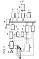
- FIG. 5 shows the circuit arrangement of the graphic computer 1 of this embodiment.
- the circuit arrangement comprises a central processing unit (CPU) 38, a system bus 39 (which comprises a data bus, an address bus and a control bus) for the CPU 38, a read only memory (ROM) 42 for storing therein a program for the CPU 38 (and video data in a demonstration mode described below), and a random access memory (RAM) 43.
- the ROM 42 and RAM 43 are connected to the system bus 39.
- the CPU 38 is supplied with the voltages (VX, Vy) corresponding to the input coordinates (X, Y) from the coordinate detecting section 37 via an analog-to-digital (A/D) converting section 40.
- the CPU 38 identifies which one of the buttons 14 and 15 to 20 has been depressed on the basis of the coordinates (X, Y). Colour data or tool data corresponding to the identified button is written into the RAM 43. When the tool buttons 15 to 20 are selected, the CPU 38 will perform the operations corresponding to those tools.
- the CPU 38 always monitors via an input/output (I/O) interface circuit inl whether the mechanical switches (the clear button 7, the sound button 57 and the executing buttons 8A, 8B shown in Figure 1) are or are not operated.
- I/O input/output
- the circuit arrangement shown in Figure 5 also comprises a video processor (VDP) 44 connected to the system bus 39, a video RAM (VRAM) 45 having a capacity of 2 frames (2 pages), and an NTSC (or PAL) encoder 46.
- VDP 44 reads out data of the input coordinates (X, Y) and colour data from the RAM 43 on the basis of commands from the CPU 38 and writes colour video data into the VRAM 45 at a corresponding address thereof. Also, it reads out coiour video data of 1 frame from the VRAM 45 periodically, and supplies same to the encoder 46.
- the encoder 46 converts the colour video data supplied thereto into a composite video signal CV and supplies the signal CV to a video signal output terminal 47.
- the VRAM 45 since the VRAM 45 has a storage capacity of 2 pages, in a certain procedure (one procedure, as mentioned above, means a process carried out during a period in which the executing button 8A or 8B is operated), the VDP 44 writes and reads video data in the region of, for example, the first page. In the next procedure, after completely moving the video data of the first page into the region of the second page, the VDP 44 writes and reads video data in the region of the second page.
- one procedure as mentioned above, means a process carried out during a period in which the executing button 8A or 8B is operated
- the VDP 44 again reads the video data in the first page region of the VRAM 45, and writes the video data into the first page region when the CPU 38 is supplied with coordinate data input. This means that the picture on the picture screen 2a of the monitor 2 returns to a picture of one procedure before by operating the cancel button 20. This results in the advantage that, when the user draws a wrong picture in the picture drawing mode, the original picture can be recovered in a one-touch fashion.
- the circuit arrangement shown in Figure 5 further comprises a counter 48, an alarm circuit 49, and a speaker 50 provided for the sound emanating section 9 (see Figure 1).
- the counter 48 keeps counting clock pulses received from the CPU 38 and the count value can be cleared at any time by a clear pulse from the CPU 38.
- the counter 48 supplies an alarm signal AL to the CPU 38.
- the CPU 38 supplies an alarm operation command or signal to the alarm circuit 49 through the I/O interface circuit 41 in response to the alarm signal AL.
- the alarm circuit 49 comprises a timer, an oscillator, a synthesiser, a power amplifier or the like, and supplies a signal in the form of a predetermined sound, melody or message to the speaker 50 through a switching circuit 58 for two minutes only in response to the alarm operation command from the CPU 38.
- the counter 48, alarm circuit 49 and speaker 50 are mainly provided in order to generate an alarm sound warning the user not to leave the power switch 6 in its ON state after he has finished using the apparatus.
- the voltage Vy generated in the coordinate detecting section 37 is supplied to the switching circuit 58 through a voltage controlled oscillator (VCO) 59 and a variable gain amplifier 60, and the voltage Vx generated in the coordinate detecting section 37 is supplied to a gain control terminal of the variable gain amplifier 60.
- the CPU 38 changes over the switching circuit 58 through the I/O interface circuit 41.
- the CPU 38 changes over the switching circuit 58 to permit an output signal of the variable gain amplifier 60 to be fed to the speaker 50.
- the CPU 38 supplies an output signal of the alarm circuit 58 to the speaker 50. Therefore, when the sound button 57 is depressed once (putting the graphic computer into a sound emanating mode) and coordinates (X, Y) are inputted by pushing the tablet 10, the speaker 50 emanates a sound whose sound volume and musical scale (that is, pitch or frequency) change in proportion to the values of the coordinates X and Y.
- the musical scale may change in accordance with the X coordinate value and the sound volume may change in accordance with the Y coordinate value. Further, the musical scale or the like may change along a diagonal line of the picture-making area 10b.
- the graphic computer 1 of this embodiment When the graphic computer 1 of this embodiment is to be used, it is necessary only, as shown in Figure 1, simply to couple the video signal output terminal of the computer 1 to the video signal input terminal of the monitor 2 via the video cable 3.
- the picture screen 2a of the monitor 2 displays thereon for a predetermined period of time a demonstration display which teaches the user an example of how to use the graphic computer 1. More specifically, a pen is displayed as a cursor on the picture screen 2a to draw a predetermined picture or an eraser is displayed as a cursor thereon to erase the picture, whereby the user can understand how to use the graphic computer 1.
- a demonstration display program is written in the ROM 42 and includes colour data, tool data and a series of data of the input coordinates (X, Y) or the like.
- the CPU 38 sequentially reads these data and moves them to the RAM 43 and the VDP 44 produces video data corresponding to the data of the RAM 43, whereby a demonstration display mode is carried out as though the user has actually drawn a locus on the tablet 10. This results in the substantial advantage that the capacity that the demonstration display program takes up in the ROM 42 can be relatively reduced.
- the graphic computer 1 of this embodiment is set into the picture drawing mode, whereby the picture displayed on the picture screen 2a of the monitor 2 is completely erased and the graphic computer 1 is set in the standby mode awaiting input from the user.
- the locus of the cursor 21 is not displayed as a picture until the executing button 8A or 8B is operated. Accordingly, the position of the cursor can be determined precisely when the user moves, for example, from a certain stop position in the drawing to a subsequent stop position.
- the graphic computer is set into the sound emanating mode by operating the sound button 57, when the user lightly touches the picture-making area 10b of the tablet 10 with a fingertip or the like the speaker 50 successively emanates sound in response to the coordinates (X, Y).
- the sound volume and the musical scale (pitch) change in proportion to the coordinates X and Y, whereby the user can play a melody or the like.
- the cursor 21 is shaped as a brush and, when the user lightly touches the picture making area 10b with the accessory pen 11 or the like, the user can paint out (fill in) with a designated colour the interior of a closed figure (circle, rectangle or the like) near the locus of the brush-shaped cursor within a previously drawn picture.
- an eraser-shaped cursor 21a is displayed in the background of a previously drawn picture on the picture screen 2a of the monitor 2 shown in Figure 6A and, when the user depresses the executing button 8A or 8B while moving the attachment pen 11 or the like, the previously drawn picture can be partly erased. If the picture is erased too much, the picture screen 2a can be returned to the previous picture produced before, by depressing the cancel button 20 in the menu selecting area 10c, as shown in Figure 6B.
- stamp button 19 If the user depresses the stamp button 19 in the menu selecting area 10c, several kinds of stamp characters 51 are displayed in the upper portion of the picture screen 2a of the monitor 2 as shown in Figure 7. If the user then pushes the tablet 10 at a portion corresponding to a desired one of the stamp characters 51, that character is selected as a cursor. If the user depresses the executing button 8A or 8B while lightly touching the tablet 10 with the accessory pen 11 or the like, a desired stamp character will be displayed on the picture screen at a position of the pen designated by when the executing button 8A or 8B is depressed. (The stamp character can be superimposed upon a previously drawn picture.)
- the pressure sensitive type position sensing means 23 including the tablet 10, the CPU 38, the VDP 44, the VRAM 45, and the NTSC encoder 46 or the like are formed as one body, that is in one unit, whereby the user can make the apparatus ready to draw a picture with ease simply by connecting the graphic computer 1 and the monitor 2 via the video cable 3. That is, the arrangement of the apparatus or system is simple and children can use the graphic computer with ease. Thus, the apparatus or system of this embodiment is eminently suitable for use by children to draw pictures.
- a play card 52 which is a flexible sheet having a predetermined character 53 printed on one or both surfaces thereof as shown in Figure 8, can be loaded on the picture-making area 10b of the tablet 10 of the graphic computer 1.
- the play card 52 is substantially rectangular, and has two protruding portions (inserting portions) 52b, 52c formed on an upper side portion thereof, two protruding portions (inserting portions) 52d, 52e formed on a lower side portion thereof, and a semicircular notch 52a for ejecting the play card 52 formed on a left side portion thereof.
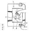
- the inserting portions 52b and 52c of the upper side portion of the play card 52 are respectively inserted into the slots 4b and 4 adjacent to the tablet 10 on the upper casing in of the graphic computer 1 while the play card 52 is slightly deformed as shown in Figure 9. Then, the inserting portions 52d and 52e of the lower side portion of the play card 52 are respectively inserted into the slots 4d and 4e of the upper casing 4 (see Figure 1), whereby the play card 52 is stably loaded on the tablet 10 in a flat manner as shown in Figure 10.
- the play card 52 can be used in a variety of ways, for example for tracing, sound play, playing a puzzle game or the like. If the user selects tracing, respective portions of the character 53 of the play card 52 shown in Figure 8 are marked with, for example, numerals such as 1′, 2′, 3′, .... . In one case, the user will trace the respective portions of the character 53 in the order 1′, 3′, 5′, 8′, .... . In another case, the user will trace the respective portions of the character 53 in the order 1′, 2′, 4′, 7′, ... so that, for example, respective different animal characters are displayed on the picture screen 2a of the monitor 2 in accordance with the order of tracing. In other words, a kind of hidden picture search play becomes possible.
- a predetermined curve or locus 61 ( Figure 10) is printed, for example, on the play card 52 in advance. If the user traces the curve 61 with a fingertip or the like after setting the graphic computer in the sound emanating mode by operating the sound button 57, a predetermined melody or the like will be produced. Further, a variant of the play card 52 may be employed in which the surface thereof is partitioned at every musical scale interval to provide areas in which the tonic solfa characters (for example) "do", “re”, “mi”, etc. are provided.
- words having ciphers are printed at some positions on the play card 52 and the user writes words while guessing the ciphers.
- the play card 52 is used, the system in the example of Figure 1 can be applied, not only to picture drawing, but also to a sophisticated play or to a kind of learning. Since the play card 52 is provided with the inserting portions 52b and 52e while the slots 4b to 4e are formed on the portion in which the upper casing 4 of the graphic computer 1 contacts the tablet 10, the play card 52 can be loaded on the graphic computer with ease. Moreover, since the play card 52 is provided with the notch 52a for gripping the play card, the play card can be ejected from the graphic computer 1 with ease.
- a leaf spring may be provided on an edge portion of the recess 4a of the upper casing 4 in order to fix a peripheral section of the play card 52. In that case, the play card need not be provided with the inserting portions 52b to 52e.
- the counter 48 keeps counting the clock pulses from the CPU 38.
- the CPU 38 causes the counter 48 to clear the count value.
- the CPU 38 holds the condition of the counter 48 in which the count value of the counter 48 is cleared.
- the count value of the counter 48 reaches the value equivalent to five minutes so that the counter 48 supplies the alarm signal AL to the CPU 38.
- the CPU 38 Upon receiving the alarm signal AL, since the CPU 38 changes over the switching circuit 58 through the I/O interface circuit 41 to cause the alarm circuit 49 to perform the alarm operation whereby an alarm sound, such as a predetermined sound, melody, message etc., emanates from the speaker 50 for two minutes. Thus, the user is warned that he has inadvertently left the power switch 6 in its ON state. If the power switch 6 is not turned OFF during the time period of two minutes during which the speaker 50 emanates sound, the CPU 38 holds the condition of the counter 48 in which the count value of the counter 48 is cleared.
- an alarm sound such as a predetermined sound, melody, message etc.
- the graphic computer 1 of this embodiment has programmed therein a demonstration mode (shop display mode) in addition to the above-described normal mode.
- the demonstration mode is utilised to display the system shown in Figure 1 so that a customer can freely operate the apparatus in a shop window of the shop.
- the user slides the power switch 6 to its ON-position while depressing the clear button 7.
- the demonstration display begins after the graphic computer 1 is powered up.
- the demonstration mode if the user depresses the clear button 7 or the executing button 8A or 8B, or if the user inputs coordinate data via the tablet 10, the displayed picture is cleared and the graphic computer is set in the picture drawing mode, in which mode the user can draw a picture freely, similarly to the normal mode.
- a program controlling the demonstration mode is so designed that, in the demonstration mode, if the user does not operate the graphic computer for five minutes (until the demonstration display is ended) after the power switch is turned ON, or if the user does not operate the graphic computer for 5 minutes during the picture drawing mode after the demonstration display is ended, the picture displayed on the picture screen 2a of the monitor 2 is cleared completely and the demonstration display is started once again. More specifically, the CPU 38, supplied with the alarm signal AL from the counter 48 when the demonstration mode is set, executes the demonstration display program once again without operating the alarm circuit 48. If the user operates the graphic computer 1 during the demonstration display mode, the picture displayed on the picture screen 2a is cleared and the graphic computer is set in the drawing mode.
- the graphic computer 1 may incorporate therein a colour or monochromatic printer (dot printer, printer-plotter, etc.) as shown in Figure 11, so that the user can print a desired picture 54 at any time.
- a colour or monochromatic printer dot printer, printer-plotter, etc.
- an integrated circuit (IC) card in which application software is written, or a voice IC card acting as a pulse signal generator or an FM sound source, etc. may be provided in the form of an attachable/detachable card 55.
- the graphic computer may incorporate therein a disc driving apparatus for a 2 inch or 3.5 inch floppy disc.
- the television monitor 2 may be replaced with a liquid crystal display (LCD) 56 as shown in Figure 12.
- the LCD 56 may be mounted on the cabinet of the graphic computer 1 so as to be freely rotatable. If the graphic computer 1 and the LCD 56 are formed unitarily in this way, the overall arrangement can be more simplified, and the graphic computer can be used more conveniently because the coordinate input section and the image display section are located close to each other. (The LCD 56 may be replaced with an electroluminescent (EL) panel.)
- EL electroluminescent
- the composite video signal CV of the graphic computer 1 is supplied to the monitor 2 or the like
- the composite video signal CV may instead or also be directly supplied to a video tape recorder or to an electronic camera, whereby the signal may be recorded on a video tape, a floppy disc or the like.
- constituent parts of the apparatus are accommodated in the same cabinet and made unitary so that the overall arrangement of the apparatus can be miniaturised.
- the apparatus can be made ready for use merely by connecting the video signal forming means to the output means (the monitor 2) via, for example, the video cable 3, so that children can operate the graphic computer 1 with ease.
- the graphic computer emanates a sound of which the musical scale (pitch) and sound volume can be changed in response to coordinates inputted to the tablet 10, the user can enjoy not only drawing a picture but also listening to the generated sound.
- the advantage results that the user can easily play a melody or the like with stress.
Description
- This invention relates to portable graphic computer apparatus.
- To create a picture, children customarily draw the picture on drawing paper with crayons and/or coloured pencils, whereby a mistake in the picture cannot easily be corrected. Also, there is a restriction on the extent to which children can freely express their ideas by drawing pictures in this way because the number of sheets of drawing paper available will generally be restricted.
- Therefore, an image forming apparatus has been proposed in which a tablet having, for example, a coordinates detecting means or apparatus, a personal computer having software for processing inputted coordinates, and a television monitor for displaying a video signal generated by the personal computer, are combined to display a locus drawn on the tablet on a picture screen of the television monitor. In this case, the picture displayed on the monitor can be corrected with ease, and the user can draw pictures freely over and over.
- An electronic picture drawing apparatus is disclosed, for example, in U S Patent No. US-A-4 764 763. In this picture drawing apparatus, coordinates are inputted by moving a cursor on a display panel by turning right and left knobs. (Accordingly, the fundamental idea of this apparatus is different from that of an embodiment of the present invention described in detail hereinbelow.)
- However, since the tablet having the coordinates detecting means and the personal computer having the predetermined software are independently provided as described above, the overall arrangement of the apparatus becomes large in size and the interconnection thereof becomes complicated. This results in the disadvantage that children cannot use the apparatus with ease.
- Moreover since electronic, relatively expensive image forming apparatus is utilised, it is desirable that more sophisticated functions than that of drawing also be provided.
- Preferred embodiments of the invention described in detail hereinbelow provide an improved portable graphic computer apparatus which can eliminate or at least reduce at least some of the above-mentioned shortcomings and disadvantages encountered with the prior art. More specifically, substantially the entire apparatus is accommodated within a cabinet and is simplified so that the apparatus is highly suited to being used by children. Also, the mechanical construction can be simplified in arrangement and other functions can be extended additionally.
- In the preferred embodiments, the speaker emanates a sound whose musical scale and sound volume can be changed in response to coordinates inputted to the tablet, thus making it possible for the user to listen to a sound as well as to draw a picture. Further, the user can play a melody or the like with stress since the sound volume and musical scale are varied in response to changing of the input coordinates in one axial direction and in another axial direction, respectively.
- Other advantageous features of the preferred embodiments are that: an alarm sound is generated so that the user is warned not inadvertently to leave a power switch of the apparatus in its ON state; demonstration video data is formed after a predetermined period of time so that the apparatus is suitable for being exhibited in a shop front for demonstration purposes; and a tracing sheet can be provided on the tablet with ease.
- European Patent Application Publication No. EP-A-O 088 565 discloses a portable graphic computer apparatus comprising:
- a tablet for inputting coordinates;
- a graphic display device for displaying coordinate values obtained by digitization of positions designated by the tablet;
- a buzzer; and
- a cabinet accommodating therein the tablet and the buzzer.
- Research Disclosure, vol. 298, February 1989, No. 29845, New York, USA, "Technique for Selection of Sound Features", discloses an audio-visual approach for selection of sound with a pointing device. As the user moves a "scroll box" on a sliding scale, the user hears the sound change and sees the chosen frequency.
- According to the present invention there is provided a portable graphic computer apparatus comprising:
- (a) a tablet for inputting coordinates;
- (b) detecting means for detecting coordinate data corresponding to coordinates inputted via the tablet;
- (c) image data forming means for forming image data from coordinate data detected by the detecting means;
- (d) a memory for storing said image data;
- (e) video signal generating means for generating a video signal from said image data;
- (f) a sound source;
- (g) a speaker connected to the sound source; and
- (h) a cabinet accommodating therein at least one of the above elements from the tablet to the speaker;
- wherein the sound source is responsive to the detected coordinate data such that the volume of the sound generated by the sound source is successively changed in accordance with a change of input coordinates to the tablet in one axial direction and the pitch of the sound generated by the sound source is successively changed in accordance with a change of input coordinates in another axial direction.
- The invention will now be further described, by way of illustrative and non-limiting example, with reference to the accompanying drawings, in which like references identify the same or similar parts throughout, and in which:
- Figure 1 is a perspective view illustrating the system arrangement of a portable graphic computer apparatus according to an embodiment of the invention;
- Figure 2 is a plan view of a portable graphic computer embodying the invention for use in the apparatus of Figure 1;
- Figures 3 and 4 are respective exploded perspective views of the portable graphic computer;
- Figure 5 is a block circuit diagram of the portable graphic computer;
- Figures 6A, 6B and 7 to 10 are schematic diagrams used to explain operation of the embodiment; and
- Figures 11 and 12 are perspective views of respective further embodiments of the invention.
- A description will now be given, with reference to the accompanying drawings, of preferred embodiments of the invention each in the form of a portable graphic computer or portable graphic computer apparatus which can be used by children to draw pictures.
- Figure 1 shows the overall system arrangement of a first embodiment. The apparatus comprises a portable
graphic computer 1 and amonitor 2 having a video signal input terminal. A video signal output terminal (described below) of thegraphic computer 1 and the video signal input terminal of themonitor 2 are coupled via avideo cable 3. A cabinet of thegraphic computer 1 is formed of anupper casing 4 and alower casing 5. A power switch 6, aclear button 7, asound button 57, and asound emanating portion 9 which covers a speaker, are provided on a right end portion of the upper casing in, and executingbuttons clear button 7,sound button 57 and executingbuttons - A rectangular cut-away or
recessed portion 4a is formed through a centre portion of theupper casing 4, and atablet 10 is provided beneath the cut-away portion 4a to act as a coordinate input surface of a pressure sensitive type position sensing means or apparatus.Slots away portion 4a at portions where the cut-awayportion 4a contacts thetablet 10, as shown in Figure 1. As described below, theslots 4b to 4e are used to attach a tracing sheet to thetablet 10. - The general operation of the apparatus will now be described. When a user draws a locus on the
tablet 10 by lightly touching thetablet 10 with an attachment oraccessory pen 11 made of a plastics material, or with a fingertip or the like, while pushing the executingbutton shaped cursor 21 is displayed on apicture screen 2a of themonitor 2, and thecursor 21 moves in tandem with the locus of the pen, fingertip or the like to display the locus as an image. (Arespective executing button tablet 10 so that both left-handed and right-handed children can operate thegraphic computer 1 with ease.) Further, if theclear button 7 is depressed, the video image on thepicture screen 2a will be erased completely and thegraphic computer 1 stands by in a picture drawing mode. - If the user depresses the
sound button 57 once whereby thetablet 10 beneath it is pushed, the apparatus causes a predetermined sound to be emanated from thesound emanating portion 9. If the user depresses thesound button 57 one more time, thesound emanating portion 9 is inhibited from emanating sound. - The coordinate input surface of the
tablet 10 is, as shown in Figure 2, divided into a picture-drawing area 10a and amenu selecting area 10c, and a portion (hatched area in Figure 2) of the picture-drawing area 10a encircled by a bracket and represented by solid circles at a predetermined pitch forms a picture-making area 10b. The aspect ratio of the picture-makingarea 10b is made coincident with the aspect ratio (3:4) of the picture screen of a standard monitor. A pixel ratio that is a ratio between resolution in the longitudinal direction (Y-direction) and resolution in the lateral direction (X-direction) of the input coordinates of thetablet 10 is made coincident with the ratio of pixels of the standard monitor. Therefore, in this embodiment, there is the advantage that, if the user draws a locus of a circle on the picture-makingarea 10b precisely, a picture of a circle is also accurately displayed on thepicture screen 2a of themonitor 2. - Sound is emanated when the user pushes the picture-
making area 10b with a fingertip or the like, the sound volume increasing successively with the positioning of the fingertip or the like along the X-axis of the input coordinates (X, Y). Also, the musical scale (pitch or frequency) of the emanated sound increases successively with the positioning of the fingertip or the like along the Y-axis (a range of about three octaves at maximum). - The
menu selecting area 10c of thetablet 10 is divided to provide acolour selecting area 12 and atool selecting area 13. The upper casing in has twelve bores orround openings 14 at thecolour selecting area 12, and six openings orslots 15 to 20 at thetool selecting area 13. If the user lightly touches thetablet 10 through one of the twelveround openings 14 with theattachment pen 11 or the like, a respective one of twelve colours (black/blue/green/yellow/red/white, etc.,) will be designated. If the user lightly touches thetablet 10 through the sixslots 15 to 20, then a respective one of five kinds of tool (bold line, very bold line, brush, eraser, stamp) and a cancel function will be designated. The one of the twelveround openings 14 and sixslots 15 to 20 that has been selected can be discriminated on the basis of the input coordinates to thetablet 10. - As described above, according to this embodiment, colour, tool and cancel functions are identified on the basis of input coordinates, and thus the mechanical construction can be simplified. Further, there is the advantage that various other functions can additionally be provided simply by sub-dividing or extending the
menu selecting area 10c. - For convenience of explanation, the twelve
round openings 14 will be referred to hereinafter ascolour selecting buttons 14 and the sixslots 15 to 20 will be referred to hereinafter as thebold line button 15, the verybold line button 16, thebrush button 17, theeraser button 18, thestamp button 19 and the cancelbutton 20, respectively. (Thebuttons buttons 15 to 20 are as follows: - 1
bold line button 15 ... to draw a free curve as a bold line of 2 x 2 dots; - 2 very
bold line button 16 ... to draw a free curve by 6 x 6 columnar dots; - 3
brush button 17 ... to cause thecursor 21 within thepicture screen 2a of themonitor 2 to be shaped as a brush to paint out (fill in) a closed area in a designated colour; - 4
eraser button 18 ... to cause thecursor 21 within thepicture screen 2a of themonitor 2 to be shaped as an eraser to erase a drawn figure; - 5
stamp button 19 ... to form a video image of a pattern, selected from 28 kinds of stamps each formed of 16 x 16 dots, at a desired position; and - 6 cancel
button 20 ... to return to the picture of just one procedure before. (One procedure means a process which is finished during depression of the executingbutton - The interior structure of the
graphic computer 1 shown by way of example in Figures 1 and 2 is represented in Figures 3 and 4 (the scale of Figure 4 being enlarged with respect to Figure 3). The upper andlower casings apparatus 23 including thetablet 10 and a printedcircuit board 22. Thelower casing 5 accommodates therein a battery cell or a rechargeable battery as a power source; and is provided with abattery cover 5a. Thegraphic computer 1 of this embodiment may be driven by an AC power source adapter or the like. - The arrangement of the pressure sensitive position sensing means 23 will now be described with reference to Figure 4. Referring to Figure 4,
thin strip electrodes 25 are formed on a first insulatingsubstrate 24 at a pitch Py, and a first pressure sensitiveconductive sheet 26 made of a pressure sensitive conductive rubber, aconductive plate 27, a second pressure sensitiveconductive sheet 28 made of a pressure sensitive conductive rubber, and a second insulatingsubstrate 29 havingthin strip electrodes 30 formed on a bottom surface thereof at a pitch Px, are sequentially laminated on the first insulatingsubstrate 24. Thetablet 10 is mounted on the second insulatingsubstrate 29. Theconductive plate 27, second insulatingsubstrate 29 and thetablet 10 are all flexible. The pitch Px assumes resolution in the X-direction of the input coordinates of this embodiment, and the pitch Py assumes resolution in the Y-direction thereof. The ratio Px/Py is made to be the same as the pixel ratio of the minimum pixels of a picture screen of a standard monitor. The values of the pitches or resolutions Px and Py are, for example, about 0.3 mm. - The
thin strip electrode 30 at one end or side in the lateral direction of the second insulatingsubstrate 29 is earthed (grounded) through aswitch circuit 31, while thethin strip electrode 30 at the other end or side is connected to a DC voltage source having a voltage E1 through aswitch circuit 32. Thethin strip electrodes 30 are connected sequentially by resistors 33 having the same resistance value. Similarly, thethin strip electrode 25 at one end or side in the longitudinal direction of the second insulatingsubstrate 24 is earthed (grounded) through aswitch circuit 34, while thethin strip electrode 25 at the other end or side is connected to a DC voltage source having a voltage E2 through aswitch circuit 35. Thethin strip electrodes 25 are connected sequentially byresistors 36 having the same resistance value. - When the user pushes (applies pressure to) the
tablet 10 at a particular position, the pressure sensitiveconductive sheets switch circuits conductive plate 27 derives a voltage corresponding to the coordinate in the X-direction, whereas when the pair ofswitch circuits conductive plate 27 derives a voltage corresponding to the coordinate in the Y-direction. den the pair ofswitch circuits switch circuits conductive plate 27 are held, a coordinate detectingsection 37 generates voltages (Vx, Vy) corresponding to the input coordinates (X, Y) of thetablet 10. - A more detailed description of the pressure sensitive position sensing means 23 shown in the example of Figure 4 and a description of a modified form thereof are set out in Japanese Patent Publication No. JP-A-58-90235. (It should be noted, however, that the coordinate detecting means or device employed in apparatus embodying the invention is not limited to the pressure sensitive type.)
- Figure 5 shows the circuit arrangement of the
graphic computer 1 of this embodiment. The circuit arrangement comprises a central processing unit (CPU) 38, a system bus 39 (which comprises a data bus, an address bus and a control bus) for theCPU 38, a read only memory (ROM) 42 for storing therein a program for the CPU 38 (and video data in a demonstration mode described below), and a random access memory (RAM) 43. TheROM 42 andRAM 43 are connected to thesystem bus 39. TheCPU 38 is supplied with the voltages (VX, Vy) corresponding to the input coordinates (X, Y) from the coordinate detectingsection 37 via an analog-to-digital (A/D) convertingsection 40. If the voltages (VX, Vy) correspond to coordinates (X, Y) in the picture-makingarea 10b of thetablet 10, the coordinates (X, Y) are written into theRAM 43. If the voltages (VX, Vy) correspond to coordinates (X, Y) in themenu selecting area 10c (see Figure 2) of thetablet 10, theCPU 38 identifies which one of thebuttons RAM 43. When thetool buttons 15 to 20 are selected, theCPU 38 will perform the operations corresponding to those tools. TheCPU 38 always monitors via an input/output (I/O) interface circuit inl whether the mechanical switches (theclear button 7, thesound button 57 and the executingbuttons - The circuit arrangement shown in Figure 5 also comprises a video processor (VDP) 44 connected to the
system bus 39, a video RAM (VRAM) 45 having a capacity of 2 frames (2 pages), and an NTSC (or PAL)encoder 46. TheVDP 44 reads out data of the input coordinates (X, Y) and colour data from theRAM 43 on the basis of commands from theCPU 38 and writes colour video data into theVRAM 45 at a corresponding address thereof. Also, it reads out coiour video data of 1 frame from theVRAM 45 periodically, and supplies same to theencoder 46. Theencoder 46 converts the colour video data supplied thereto into a composite video signal CV and supplies the signal CV to a videosignal output terminal 47. In this embodiment, since theVRAM 45 has a storage capacity of 2 pages, in a certain procedure (one procedure, as mentioned above, means a process carried out during a period in which the executingbutton VDP 44 writes and reads video data in the region of, for example, the first page. In the next procedure, after completely moving the video data of the first page into the region of the second page, theVDP 44 writes and reads video data in the region of the second page. If theCPU 38 issues a cancel command to theVDP 44 when the cancelbutton 20 of thetool selecting area 13 in thetablet 10 is pushed, theVDP 44 again reads the video data in the first page region of theVRAM 45, and writes the video data into the first page region when theCPU 38 is supplied with coordinate data input. This means that the picture on thepicture screen 2a of themonitor 2 returns to a picture of one procedure before by operating the cancelbutton 20. This results in the advantage that, when the user draws a wrong picture in the picture drawing mode, the original picture can be recovered in a one-touch fashion. - The circuit arrangement shown in Figure 5 further comprises a
counter 48, analarm circuit 49, and aspeaker 50 provided for the sound emanating section 9 (see Figure 1). Thecounter 48 keeps counting clock pulses received from theCPU 38 and the count value can be cleared at any time by a clear pulse from theCPU 38. When the count value of thecounter 48 reaches a value corresponding to a time of 5 minutes, that is a clear pulse has not been supplied to thecounter 48 from theCPU 38 for five minutes, thecounter 48 supplies an alarm signal AL to theCPU 38. During the normal drawing mode, theCPU 38 supplies an alarm operation command or signal to thealarm circuit 49 through the I/O interface circuit 41 in response to the alarm signal AL. Thealarm circuit 49 comprises a timer, an oscillator, a synthesiser, a power amplifier or the like, and supplies a signal in the form of a predetermined sound, melody or message to thespeaker 50 through a switchingcircuit 58 for two minutes only in response to the alarm operation command from theCPU 38. Thecounter 48,alarm circuit 49 andspeaker 50 are mainly provided in order to generate an alarm sound warning the user not to leave the power switch 6 in its ON state after he has finished using the apparatus. - The voltage Vy generated in the coordinate detecting
section 37 is supplied to the switchingcircuit 58 through a voltage controlled oscillator (VCO) 59 and avariable gain amplifier 60, and the voltage Vx generated in the coordinate detectingsection 37 is supplied to a gain control terminal of thevariable gain amplifier 60. TheCPU 38 changes over the switchingcircuit 58 through the I/O interface circuit 41. - When the
sound button 57 is depressed once, theCPU 38 changes over the switchingcircuit 58 to permit an output signal of thevariable gain amplifier 60 to be fed to thespeaker 50. When thesound button 57 is depressed one more time, or when an alarm operation (described below) is to be carried out, theCPU 38 supplies an output signal of thealarm circuit 58 to thespeaker 50. Therefore, when thesound button 57 is depressed once (putting the graphic computer into a sound emanating mode) and coordinates (X, Y) are inputted by pushing thetablet 10, thespeaker 50 emanates a sound whose sound volume and musical scale (that is, pitch or frequency) change in proportion to the values of the coordinates X and Y. - Alternatively, the musical scale may change in accordance with the X coordinate value and the sound volume may change in accordance with the Y coordinate value. Further, the musical scale or the like may change along a diagonal line of the picture-making
area 10b. - When the
graphic computer 1 of this embodiment is to be used, it is necessary only, as shown in Figure 1, simply to couple the video signal output terminal of thecomputer 1 to the video signal input terminal of themonitor 2 via thevideo cable 3. When the user slides the power switch 6 to its ON-position, thepicture screen 2a of themonitor 2 displays thereon for a predetermined period of time a demonstration display which teaches the user an example of how to use thegraphic computer 1. More specifically, a pen is displayed as a cursor on thepicture screen 2a to draw a predetermined picture or an eraser is displayed as a cursor thereon to erase the picture, whereby the user can understand how to use thegraphic computer 1. - A demonstration display program is written in the
ROM 42 and includes colour data, tool data and a series of data of the input coordinates (X, Y) or the like. TheCPU 38 sequentially reads these data and moves them to theRAM 43 and theVDP 44 produces video data corresponding to the data of theRAM 43, whereby a demonstration display mode is carried out as though the user has actually drawn a locus on thetablet 10. This results in the substantial advantage that the capacity that the demonstration display program takes up in theROM 42 can be relatively reduced. - If, during the demonstration display mode, the user operates the
clear button 7, thesound button 57 or either of the executingbuttons menu selecting area 10c), thegraphic computer 1 of this embodiment is set into the picture drawing mode, whereby the picture displayed on thepicture screen 2a of themonitor 2 is completely erased and thegraphic computer 1 is set in the standby mode awaiting input from the user. After the user designates a colour by pushing acolour button 14 and a tool by pushing thebold line button 15 or the verybold line button 16 with theaccessory pen 11, fingertip or the like, if the user then freely draws a locus by lightly touching thepicture making area 10b with theaccessory pen 11 whilst the executingbutton picture screen 2a of themonitor 2 by thecursor 21. If the same operation is performed without depressing the executingbutton cursor 21 will move (in the background of any previously drawn picture) on thepicture screen 2a. Thus, the locus of thecursor 21 is not displayed as a picture until the executingbutton - If the graphic computer is set into the sound emanating mode by operating the
sound button 57, when the user lightly touches the picture-makingarea 10b of thetablet 10 with a fingertip or the like thespeaker 50 successively emanates sound in response to the coordinates (X, Y). This results in the advantage that the user can enjoy the sound he thereby generates. As explained above, the sound volume and the musical scale (pitch) change in proportion to the coordinates X and Y, whereby the user can play a melody or the like. - If the user depresses the
brush button 17 in themenu selecting area 10c, thecursor 21 is shaped as a brush and, when the user lightly touches thepicture making area 10b with theaccessory pen 11 or the like, the user can paint out (fill in) with a designated colour the interior of a closed figure (circle, rectangle or the like) near the locus of the brush-shaped cursor within a previously drawn picture. - If the user depresses the
eraser button 18 in themenu selecting area 10c and lightly touches the picture-makingarea 10b with theaccessory pen 11 or the like, an eraser-shapedcursor 21a is displayed in the background of a previously drawn picture on thepicture screen 2a of themonitor 2 shown in Figure 6A and, when the user depresses the executingbutton attachment pen 11 or the like, the previously drawn picture can be partly erased. If the picture is erased too much, thepicture screen 2a can be returned to the previous picture produced before, by depressing the cancelbutton 20 in themenu selecting area 10c, as shown in Figure 6B. - If the user depresses the
stamp button 19 in themenu selecting area 10c, several kinds ofstamp characters 51 are displayed in the upper portion of thepicture screen 2a of themonitor 2 as shown in Figure 7. If the user then pushes thetablet 10 at a portion corresponding to a desired one of thestamp characters 51, that character is selected as a cursor. If the user depresses the executingbutton tablet 10 with theaccessory pen 11 or the like, a desired stamp character will be displayed on the picture screen at a position of the pen designated by when the executingbutton - As described above, in the
graphic computer 1 of this embodiment, the pressure sensitive type position sensing means 23 including thetablet 10, theCPU 38, theVDP 44, theVRAM 45, and theNTSC encoder 46 or the like are formed as one body, that is in one unit, whereby the user can make the apparatus ready to draw a picture with ease simply by connecting thegraphic computer 1 and themonitor 2 via thevideo cable 3. That is, the arrangement of the apparatus or system is simple and children can use the graphic computer with ease. Thus, the apparatus or system of this embodiment is eminently suitable for use by children to draw pictures. - In this embodiment, a
play card 52, which is a flexible sheet having apredetermined character 53 printed on one or both surfaces thereof as shown in Figure 8, can be loaded on the picture-makingarea 10b of thetablet 10 of thegraphic computer 1. Theplay card 52 is substantially rectangular, and has two protruding portions (inserting portions) 52b, 52c formed on an upper side portion thereof, two protruding portions (inserting portions) 52d, 52e formed on a lower side portion thereof, and asemicircular notch 52a for ejecting theplay card 52 formed on a left side portion thereof. - When the
play card 52 is loaded on thegraphic computer 1 of this embodiment, the insertingportions play card 52 are respectively inserted into theslots tablet 10 on the upper casing in of thegraphic computer 1 while theplay card 52 is slightly deformed as shown in Figure 9. Then, the insertingportions play card 52 are respectively inserted into theslots play card 52 is stably loaded on thetablet 10 in a flat manner as shown in Figure 10. - The
play card 52 can be used in a variety of ways, for example for tracing, sound play, playing a puzzle game or the like. If the user selects tracing, respective portions of thecharacter 53 of theplay card 52 shown in Figure 8 are marked with, for example, numerals such as 1′, 2′, 3′, .... . In one case, the user will trace the respective portions of thecharacter 53 in theorder 1′, 3′, 5′, 8′, .... . In another case, the user will trace the respective portions of thecharacter 53 in theorder 1′, 2′, 4′, 7′, ... so that, for example, respective different animal characters are displayed on thepicture screen 2a of themonitor 2 in accordance with the order of tracing. In other words, a kind of hidden picture search play becomes possible. - In the case of sound play, a predetermined curve or locus 61 (Figure 10) is printed, for example, on the
play card 52 in advance. If the user traces thecurve 61 with a fingertip or the like after setting the graphic computer in the sound emanating mode by operating thesound button 57, a predetermined melody or the like will be produced. Further, a variant of theplay card 52 may be employed in which the surface thereof is partitioned at every musical scale interval to provide areas in which the tonic solfa characters (for example) "do", "re", "mi", etc. are provided. - In the case of playing a puzzle game, words having ciphers are printed at some positions on the
play card 52 and the user writes words while guessing the ciphers. - If, as described above, the
play card 52 is used, the system in the example of Figure 1 can be applied, not only to picture drawing, but also to a sophisticated play or to a kind of learning. Since theplay card 52 is provided with the insertingportions slots 4b to 4e are formed on the portion in which theupper casing 4 of thegraphic computer 1 contacts thetablet 10, theplay card 52 can be loaded on the graphic computer with ease. Moreover, since theplay card 52 is provided with thenotch 52a for gripping the play card, the play card can be ejected from thegraphic computer 1 with ease. - Instead of forming the
grooves 4b to 4e on theupper casing 4, a leaf spring may be provided on an edge portion of therecess 4a of theupper casing 4 in order to fix a peripheral section of theplay card 52. In that case, the play card need not be provided with the insertingportions 52b to 52e. - The operation of the
counter 48 and thealarm circuit 49 in this embodiment will now be described. In the normal picture drawing mode, thecounter 48 keeps counting the clock pulses from theCPU 38. Each time coordinate data (involving themenu selecting area 10c) are inputted via thetablet 10, or theclear button 7 or the executingbutton CPU 38 causes thecounter 48 to clear the count value. When the demonstration display is carried out after the graphic computer is powered up, theCPU 38 holds the condition of thecounter 48 in which the count value of thecounter 48 is cleared. In the normal picture drawing mode, if the user has neither touched thetablet 10 nor depressed any mechanical switch for five minutes, such as when the power switch 6 has inadvertently not been turned OFF (including the case in which the user has not carried out any operation for five minutes after completion of the demonstration display), the count value of thecounter 48 reaches the value equivalent to five minutes so that thecounter 48 supplies the alarm signal AL to theCPU 38. - Upon receiving the alarm signal AL, since the
CPU 38 changes over the switchingcircuit 58 through the I/O interface circuit 41 to cause thealarm circuit 49 to perform the alarm operation whereby an alarm sound, such as a predetermined sound, melody, message etc., emanates from thespeaker 50 for two minutes. Thus, the user is warned that he has inadvertently left the power switch 6 in its ON state. If the power switch 6 is not turned OFF during the time period of two minutes during which thespeaker 50 emanates sound, theCPU 38 holds the condition of thecounter 48 in which the count value of thecounter 48 is cleared. - The
graphic computer 1 of this embodiment has programmed therein a demonstration mode (shop display mode) in addition to the above-described normal mode. The demonstration mode is utilised to display the system shown in Figure 1 so that a customer can freely operate the apparatus in a shop window of the shop. To set the graphic computer in the demonstration mode, the user slides the power switch 6 to its ON-position while depressing theclear button 7. In the demonstration mode, the demonstration display begins after thegraphic computer 1 is powered up. During the demonstration mode, if the user depresses theclear button 7 or the executingbutton tablet 10, the displayed picture is cleared and the graphic computer is set in the picture drawing mode, in which mode the user can draw a picture freely, similarly to the normal mode. - A program controlling the demonstration mode is so designed that, in the demonstration mode, if the user does not operate the graphic computer for five minutes (until the demonstration display is ended) after the power switch is turned ON, or if the user does not operate the graphic computer for 5 minutes during the picture drawing mode after the demonstration display is ended, the picture displayed on the
picture screen 2a of themonitor 2 is cleared completely and the demonstration display is started once again. More specifically, theCPU 38, supplied with the alarm signal AL from thecounter 48 when the demonstration mode is set, executes the demonstration display program once again without operating thealarm circuit 48. If the user operates thegraphic computer 1 during the demonstration display mode, the picture displayed on thepicture screen 2a is cleared and the graphic computer is set in the drawing mode. This means that, if thegraphic computer 1 is not operated at all for five minutes after the customer freely draws a picture when the system according to the example of Figure 1 is exhibited in a shop window, the picture drawn by the customer is automatically erased and the demonstration display is started once again. Therefore, according to this demonstration mode, when thegraphic computer 1 is exhibited at the shop front, the salesman need not clear the picture drawn by the customer, thus making the graphic computer easy to handle. - The
graphic computer 1 may incorporate therein a colour or monochromatic printer (dot printer, printer-plotter, etc.) as shown in Figure 11, so that the user can print a desiredpicture 54 at any time. In order to complement theROM 42 in Figure 5, an integrated circuit (IC) card in which application software is written, or a voice IC card acting as a pulse signal generator or an FM sound source, etc., may be provided in the form of an attachable/detachable card 55. Alternatively, the graphic computer may incorporate therein a disc driving apparatus for a 2 inch or 3.5 inch floppy disc. - While, in the above embodiments, the
graphic computer 1 and thetelevision monitor 2 are provided independently, thetelevision monitor 2 may be replaced with a liquid crystal display (LCD) 56 as shown in Figure 12. TheLCD 56 may be mounted on the cabinet of thegraphic computer 1 so as to be freely rotatable. If thegraphic computer 1 and theLCD 56 are formed unitarily in this way, the overall arrangement can be more simplified, and the graphic computer can be used more conveniently because the coordinate input section and the image display section are located close to each other. (TheLCD 56 may be replaced with an electroluminescent (EL) panel.) - While, in the above-described embodiments, the composite video signal CV of the
graphic computer 1 is supplied to themonitor 2 or the like, the composite video signal CV may instead or also be directly supplied to a video tape recorder or to an electronic camera, whereby the signal may be recorded on a video tape, a floppy disc or the like. - According to the embodiments of Figures 1 to 11, constituent parts of the apparatus, except for an output means, are accommodated in the same cabinet and made unitary so that the overall arrangement of the apparatus can be miniaturised. Also, the apparatus can be made ready for use merely by connecting the video signal forming means to the output means (the monitor 2) via, for example, the
video cable 3, so that children can operate thegraphic computer 1 with ease. - Further, since the graphic computer emanates a sound of which the musical scale (pitch) and sound volume can be changed in response to coordinates inputted to the
tablet 10, the user can enjoy not only drawing a picture but also listening to the generated sound. - More specifically, since the sound volume and the musical scale are changed in response to a change of input coordinates in one axial direction and in the other axial direction, respectively, the advantage results that the user can easily play a melody or the like with stress.
Claims (4)
- A portable graphic computer apparatus comprising:(a) a tablet (10) for inputting coordinates;(b) detecting means (23) for detecting coordinate data corresponding to coordinates inputted via the tablet (10);(c) image data forming means (37, 38, 40) for forming image data from coordinate data detected by the detecting means;(d) a memory (43) for storing said image data;(e) video signal generating means (38, 44, 45, 46) for generating a video signal from said image data;(f) a sound source (59, 60);(g) a speaker (50) connected to the sound source (59, 60); and(h) a cabinet (4, 5) accommodating therein at least one of the above elements from the tablet (10) to the speaker (50);wherein the sound source (59, 60) is responsive to the detected coordinate data such that the volume of the sound generated by the sound source (59, 60) is successively changed in accordance with a change of input coordinates to the tablet (10) in one axial direction and the pitch of the sound generated by the sound source is successively changed in accordance with a change of input coordinates in another axial direction.
- Apparatus according to claim 1, comprising a sound button (57) for selectively controlling the coordinate detecting means (23) so that the sound source (59, 60) is driven by an output signal of the coordinate detecting means (23).
- Apparatus according to claim 2, wherein the sound button (57) is provided on the cabinet (4, 5).
- Apparatus according to any of the preceding claims, wherein the cabinet (4, 5) comprises means (4b to 4e) for mounting a tracing sheet (52) on peripheral portions of the tablet (10) in the cabinet (4, 5).
Applications Claiming Priority (2)
| Application Number | Priority Date | Filing Date | Title |
|---|---|---|---|
| JP21982089A JP2784811B2 (en) | 1989-08-25 | 1989-08-25 | Image creation device |
| JP219820/89 | 1989-08-25 |
Publications (3)
| Publication Number | Publication Date |
|---|---|
| EP0414566A2 EP0414566A2 (en) | 1991-02-27 |
| EP0414566A3 EP0414566A3 (en) | 1992-10-07 |
| EP0414566B1 true EP0414566B1 (en) | 1996-06-19 |
Family
ID=16741550
Family Applications (1)
| Application Number | Title | Priority Date | Filing Date |
|---|---|---|---|
| EP90309328A Expired - Lifetime EP0414566B1 (en) | 1989-08-25 | 1990-08-24 | Portable graphic computer apparatus |
Country Status (9)
| Country | Link |
|---|---|
| US (1) | US5670992A (en) |
| EP (1) | EP0414566B1 (en) |
| JP (1) | JP2784811B2 (en) |
| KR (1) | KR930005806B1 (en) |
| AU (1) | AU622824B2 (en) |
| BR (1) | BR9004180A (en) |
| CA (1) | CA2023965C (en) |
| DE (1) | DE69027489T2 (en) |
| ES (1) | ES2088417T3 (en) |
Families Citing this family (72)
| Publication number | Priority date | Publication date | Assignee | Title |
|---|---|---|---|---|
| AU622823B2 (en) * | 1989-08-25 | 1992-04-16 | Sony Corporation | Portable graphic computer apparatus |
| JP2952955B2 (en) * | 1990-04-19 | 1999-09-27 | ソニー株式会社 | Image creation device |
| AU3221493A (en) * | 1991-12-10 | 1993-07-19 | Khyber Technologies Corporation | Portable messaging and scheduling device with homebase station |
| US6961004B2 (en) | 1991-12-10 | 2005-11-01 | Rajendra Kumar | Portable messaging and scheduling device with homebase station |
| IT1252551B (en) * | 1991-12-19 | 1995-06-19 | Alcatel Italia | CIRCUIT FOR THE RECOGNITION OF SPEAKING |
| JP3026472B2 (en) * | 1991-12-31 | 2000-03-27 | インターナショナル・ビジネス・マシーンズ・コーポレイション | Method and apparatus for providing audio output |
| US5594471A (en) * | 1992-01-09 | 1997-01-14 | Casco Development, Inc. | Industrial touchscreen workstation with programmable interface and method |
| JPH05342164A (en) * | 1992-05-21 | 1993-12-24 | Internatl Business Mach Corp <Ibm> | Information processing system with printing function |
| US5420607A (en) * | 1992-09-02 | 1995-05-30 | Miller; Robert F. | Electronic paintbrush and color palette |
| US5604517A (en) * | 1994-01-14 | 1997-02-18 | Binney & Smith Inc. | Electronic drawing device |
| TW357913U (en) * | 1994-10-12 | 1999-05-01 | Sega Enterprises Kk | Peripheral machinery |
| CA2163316A1 (en) * | 1994-11-21 | 1996-05-22 | Roger L. Collins | Interactive play with a computer |
| US6005545A (en) * | 1995-01-17 | 1999-12-21 | Sega Enterprise, Ltd. | Image processing method and electronic device |
| US5691897A (en) | 1995-05-30 | 1997-11-25 | Roy-G-Biv Corporation | Motion control systems |
| US6542925B2 (en) | 1995-05-30 | 2003-04-01 | Roy-G-Biv Corporation | Generation and distribution of motion commands over a distributed network |
| US20060206219A1 (en) * | 1995-05-30 | 2006-09-14 | Brown David W | Motion control systems and methods |
| US6571141B1 (en) | 1995-05-30 | 2003-05-27 | Roy-G-Biv Corporation | Application programs for motion control devices including access limitations |
| US7137107B1 (en) | 2003-04-29 | 2006-11-14 | Roy-G-Biv Corporation | Motion control systems and methods |
| US7139843B1 (en) | 1995-05-30 | 2006-11-21 | Roy-G-Biv Corporation | System and methods for generating and communicating motion data through a distributed network |
| US6859671B1 (en) | 1995-05-30 | 2005-02-22 | Roy-G-Biv Corporation | Application programs for motion control devices including access limitations |
| US7024666B1 (en) | 2002-01-28 | 2006-04-04 | Roy-G-Biv Corporation | Motion control systems and methods |
| US6941543B1 (en) | 1995-05-30 | 2005-09-06 | Roy-G-Biv Corporation | Motion control system and method |
| US6209037B1 (en) | 1995-05-30 | 2001-03-27 | Roy-G-Biv Corporation | Motion control systems using communication map to facilitating communication with motion control hardware |
| US20120009557A1 (en) * | 1995-12-29 | 2012-01-12 | Marcus Brian I | Interactive apparatus having contact sensitive display screen capable of detecting two or more coincident contacts |
| US5823782A (en) * | 1995-12-29 | 1998-10-20 | Tinkers & Chance | Character recognition educational system |
| TW394879B (en) * | 1996-02-09 | 2000-06-21 | Sega Enterprises Kk | Graphics processing system and its data input device |
| JP3709447B2 (en) * | 1996-03-29 | 2005-10-26 | 株式会社セガ | Tablet unit |
| JPH10124689A (en) * | 1996-10-15 | 1998-05-15 | Nikon Corp | Image recorder/reproducer |
| US6215505B1 (en) | 1997-06-20 | 2001-04-10 | Nippon Telegraph And Telephone Corporation | Scheme for interactive video manipulation and display of moving object on background image |
| US20010032278A1 (en) * | 1997-10-07 | 2001-10-18 | Brown Stephen J. | Remote generation and distribution of command programs for programmable devices |
| US6717567B1 (en) * | 1998-01-07 | 2004-04-06 | Intel Corporation | Wireless digital picture display frame |
| US6160539A (en) * | 1998-06-08 | 2000-12-12 | Wacom Co., Ltd. | Digitizer system with cursor shape changing as a function of pointer location on menu strip |
| EP0967540A3 (en) * | 1998-06-26 | 2002-09-04 | Wacom Co., Ltd. | Digitizer system with cursor shape change |
| US7410471B1 (en) | 1998-09-18 | 2008-08-12 | Becker Orthopedic Appliance Company | Orthosis knee joint and sensor |
| US6517503B1 (en) | 1998-09-18 | 2003-02-11 | Becker Orthopedic Appliance Company | Orthosis knee joint |
| JP2000112451A (en) * | 1998-10-08 | 2000-04-21 | Sony Computer Entertainment Inc | Electronic instrument and auxiliary information display device |
| FR2790566A1 (en) * | 1999-03-02 | 2000-09-08 | Philippe Soulie | Portable pocket computer, agenda or electronic message transmitter/receiver with combinatory touch type keyboard |
| US6238217B1 (en) * | 1999-05-17 | 2001-05-29 | Cec Entertainment, Inc. | Video coloring book |
| US8032605B2 (en) | 1999-10-27 | 2011-10-04 | Roy-G-Biv Corporation | Generation and distribution of motion commands over a distributed network |
| JP2003513348A (en) | 1999-10-27 | 2003-04-08 | ロイ ジー ビヴ コーポレイション | System and method for generating and communicating athletic data via a distributed network |
| US6885898B1 (en) | 2001-05-18 | 2005-04-26 | Roy-G-Biv Corporation | Event driven motion systems |
| US6585554B1 (en) | 2000-02-11 | 2003-07-01 | Mattel, Inc. | Musical drawing assembly |
| JP4562294B2 (en) * | 2001-01-26 | 2010-10-13 | 富士通株式会社 | Touch panel device |
| US7031798B2 (en) | 2001-02-09 | 2006-04-18 | Roy-G-Biv Corporation | Event management systems and methods for the distribution of motion control commands |
| US7904194B2 (en) | 2001-02-09 | 2011-03-08 | Roy-G-Biv Corporation | Event management systems and methods for motion control systems |
| US20030067447A1 (en) | 2001-07-09 | 2003-04-10 | Geaghan Bernard O. | Touch screen with selective touch sources |
| US7034814B2 (en) * | 2001-07-13 | 2006-04-25 | Apple Computer, Inc. | Methods and apparatuses using control indicators for data processing systems |
| CN1280698C (en) * | 2001-09-24 | 2006-10-18 | 皇家飞利浦电子股份有限公司 | Interactive system and method of interaction |
| US6981293B2 (en) * | 2002-08-23 | 2006-01-03 | Rochelle Steinberg | Personal hygiene accessory |
| US7200560B2 (en) * | 2002-11-19 | 2007-04-03 | Medaline Elizabeth Philbert | Portable reading device with display capability |
| US7083420B2 (en) * | 2003-02-10 | 2006-08-01 | Leapfrog Enterprises, Inc. | Interactive handheld apparatus with stylus |
| WO2004075004A2 (en) * | 2003-02-14 | 2004-09-02 | Mattel, Inc. | Hand-held interactive electronic device |
| EP1457867A1 (en) * | 2003-03-14 | 2004-09-15 | Koninklijke Philips Electronics N.V. | System for adjusting a combination of control parameters |
| US8027349B2 (en) | 2003-09-25 | 2011-09-27 | Roy-G-Biv Corporation | Database event driven motion systems |
| US20060064503A1 (en) | 2003-09-25 | 2006-03-23 | Brown David W | Data routing systems and methods |
| US7249950B2 (en) | 2003-10-10 | 2007-07-31 | Leapfrog Enterprises, Inc. | Display apparatus for teaching writing |
| JP4185019B2 (en) * | 2004-05-13 | 2008-11-19 | 株式会社東芝 | Display device with audio output |
| JP4636845B2 (en) | 2004-10-07 | 2011-02-23 | 任天堂株式会社 | GAME DEVICE AND GAME PROGRAM |
| US20060166592A1 (en) * | 2005-01-26 | 2006-07-27 | Nielsen Paul S | Electronic drawing toy |
| US7887058B2 (en) * | 2005-07-07 | 2011-02-15 | Mattel, Inc. | Methods of playing drawing games and electronic game systems adapted to interactively provide the same |
| US7697827B2 (en) | 2005-10-17 | 2010-04-13 | Konicek Jeffrey C | User-friendlier interfaces for a camera |
| US8574050B2 (en) | 2005-11-04 | 2013-11-05 | Mattel, Inc. | Game unit with dual joystick controllers |
| US7874918B2 (en) | 2005-11-04 | 2011-01-25 | Mattel Inc. | Game unit with motion and orientation sensing controller |
| US8568213B2 (en) | 2005-11-04 | 2013-10-29 | Mattel, Inc. | Game unit with controller-determined characters |
| US8655258B2 (en) * | 2006-10-17 | 2014-02-18 | Vtech Electronics Ltd. | PC connectable electronic learning aid device with replaceable activity worksheets |
| US8187051B2 (en) | 2007-10-26 | 2012-05-29 | Mattel, Inc. | Digital arts and crafts computer peripheral toy device |
| JP5080383B2 (en) | 2008-06-25 | 2012-11-21 | スリーエム イノベイティブ プロパティズ カンパニー | Operator identification device, operator identification method, and in-vehicle device |
| DE112010003602T5 (en) * | 2009-09-09 | 2012-08-23 | Mattel, Inc. | System and method for displaying, navigating and selecting electronically stored content on a multifunctional hand-held device |
| US8629754B2 (en) * | 2009-12-15 | 2014-01-14 | Echostar Technologies L.L.C. | Audible feedback for input activation of a remote control device |
| US20130188220A1 (en) * | 2012-01-17 | 2013-07-25 | Toshiba Tec Kabushiki Kaisha | Image forming apparatus and computer |
| US9809049B2 (en) | 2013-10-04 | 2017-11-07 | Comsero, Inc. | Tablet with interconnection features |
| USD747955S1 (en) | 2014-05-08 | 2016-01-26 | Comsero, LLC | Mounting bracket |
Family Cites Families (6)
| Publication number | Priority date | Publication date | Assignee | Title |
|---|---|---|---|---|
| US3778910A (en) * | 1972-06-22 | 1973-12-18 | L Smalligan | Writing aid |
| AU6541374A (en) * | 1973-02-08 | 1975-08-14 | Unisearch Ltd | Electronic music |
| JPS58149578A (en) * | 1982-02-27 | 1983-09-05 | Fanuc Ltd | Setting system of information input area |
| US4604062A (en) * | 1985-07-29 | 1986-08-05 | Woods Margaret H | Drawing/tracing/template apparatus |
| US4764763A (en) * | 1985-12-13 | 1988-08-16 | The Ohio Art Company | Electronic sketching device |
| US4912466A (en) * | 1988-09-15 | 1990-03-27 | Npd Research Inc. | Audio frequency based data capture tablet |
-
1989
- 1989-08-25 JP JP21982089A patent/JP2784811B2/en not_active Expired - Lifetime
-
1990
- 1990-08-15 AU AU60986/90A patent/AU622824B2/en not_active Ceased
- 1990-08-22 KR KR1019900012950A patent/KR930005806B1/en not_active IP Right Cessation
- 1990-08-23 BR BR909004180A patent/BR9004180A/en not_active IP Right Cessation
- 1990-08-24 EP EP90309328A patent/EP0414566B1/en not_active Expired - Lifetime
- 1990-08-24 CA CA002023965A patent/CA2023965C/en not_active Expired - Lifetime
- 1990-08-24 ES ES90309328T patent/ES2088417T3/en not_active Expired - Lifetime
- 1990-08-24 DE DE69027489T patent/DE69027489T2/en not_active Expired - Fee Related
-
1992
- 1992-09-23 US US07/950,975 patent/US5670992A/en not_active Expired - Lifetime
Also Published As
| Publication number | Publication date |
|---|---|
| KR910005143A (en) | 1991-03-30 |
| JPH0383118A (en) | 1991-04-09 |
| CA2023965C (en) | 1994-02-22 |
| JP2784811B2 (en) | 1998-08-06 |
| AU622824B2 (en) | 1992-04-16 |
| BR9004180A (en) | 1991-09-03 |
| DE69027489D1 (en) | 1996-07-25 |
| CA2023965A1 (en) | 1991-02-26 |
| US5670992A (en) | 1997-09-23 |
| EP0414566A2 (en) | 1991-02-27 |
| KR930005806B1 (en) | 1993-06-25 |
| EP0414566A3 (en) | 1992-10-07 |
| ES2088417T3 (en) | 1996-08-16 |
| AU6098690A (en) | 1991-03-14 |
| DE69027489T2 (en) | 1996-12-12 |
Similar Documents
| Publication | Publication Date | Title |
|---|---|---|
| EP0414566B1 (en) | Portable graphic computer apparatus | |
| EP0667568B1 (en) | Portable graphic computer apparatus | |
| US5511983A (en) | Graphic image generating apparatus with automatic demonstration image generating program | |
| US20030104343A1 (en) | Electronic drawing assist toy | |
| CA2023962C (en) | Portable graphic computer apparatus | |
| JP2797642B2 (en) | Coordinate input device and coordinate information input auxiliary member | |
| JP3185714B2 (en) | Image creation apparatus and image creation method | |
| JP3082200B2 (en) | Image creation device | |
| KR930005805B1 (en) | Image processing apparatus and cover sheet therefor | |
| JP4663039B2 (en) | Position input device | |
| JPH04326112A (en) | Input device of image generation device | |
| JPH04328623A (en) | Input device for image forming device | |
| EP0498307B1 (en) | Information processing apparatus | |
| JPH04111627U (en) | Coordinate information input support member | |
| JPH0721791B2 (en) | Graph making device | |
| JP2004147998A (en) | Controller for game machine | |
| JPH05342319A (en) | Image forming device | |
| JPH08123762A (en) | Compact electronic equipment | |
| Ellis et al. | Workstation Technology | |
| JPH04188315A (en) | Information input controller | |
| CN1728055A (en) | Keyboard and method for defining functions of keyboard | |
| JPH0297125A (en) | Multi-item input device | |
| JPH10187326A (en) | Switch device | |
| JPS60109368A (en) | Graphic input and output device |
Legal Events
| Date | Code | Title | Description |
|---|---|---|---|
| PUAI | Public reference made under article 153(3) epc to a published international application that has entered the european phase |
Free format text: ORIGINAL CODE: 0009012 |
|
| AK | Designated contracting states |
Kind code of ref document: A2 Designated state(s): DE ES FR GB NL |
|
| PUAL | Search report despatched |
Free format text: ORIGINAL CODE: 0009013 |
|
| AK | Designated contracting states |
Kind code of ref document: A3 Designated state(s): DE ES FR GB NL |
|
| 17P | Request for examination filed |
Effective date: 19930217 |
|
| 17Q | First examination report despatched |
Effective date: 19950113 |
|
| GRAH | Despatch of communication of intention to grant a patent |
Free format text: ORIGINAL CODE: EPIDOS IGRA |
|
| RAP1 | Party data changed (applicant data changed or rights of an application transferred) |
Owner name: SONY CORPORATION |
|
| GRAA | (expected) grant |
Free format text: ORIGINAL CODE: 0009210 |
|
| AK | Designated contracting states |
Kind code of ref document: B1 Designated state(s): DE ES FR GB NL |
|
| REG | Reference to a national code |
Ref country code: ES Ref legal event code: BA2A Ref document number: 2088417 Country of ref document: ES Kind code of ref document: T3 |
|
| REF | Corresponds to: |
Ref document number: 69027489 Country of ref document: DE Date of ref document: 19960725 |
|
| REG | Reference to a national code |
Ref country code: ES Ref legal event code: FG2A Ref document number: 2088417 Country of ref document: ES Kind code of ref document: T3 |
|
| ET | Fr: translation filed | ||
| PLBE | No opposition filed within time limit |
Free format text: ORIGINAL CODE: 0009261 |
|
| STAA | Information on the status of an ep patent application or granted ep patent |
Free format text: STATUS: NO OPPOSITION FILED WITHIN TIME LIMIT |
|
| 26N | No opposition filed | ||
| PGFP | Annual fee paid to national office [announced via postgrant information from national office to epo] |
Ref country code: FR Payment date: 20010810 Year of fee payment: 12 |
|
| PGFP | Annual fee paid to national office [announced via postgrant information from national office to epo] |
Ref country code: DE Payment date: 20010820 Year of fee payment: 12 |
|
| PGFP | Annual fee paid to national office [announced via postgrant information from national office to epo] |
Ref country code: GB Payment date: 20010822 Year of fee payment: 12 |
|
| PGFP | Annual fee paid to national office [announced via postgrant information from national office to epo] |
Ref country code: ES Payment date: 20010824 Year of fee payment: 12 |
|
| PGFP | Annual fee paid to national office [announced via postgrant information from national office to epo] |
Ref country code: NL Payment date: 20010830 Year of fee payment: 12 |
|
| REG | Reference to a national code |
Ref country code: GB Ref legal event code: IF02 |
|
| PG25 | Lapsed in a contracting state [announced via postgrant information from national office to epo] |
Ref country code: GB Free format text: LAPSE BECAUSE OF NON-PAYMENT OF DUE FEES Effective date: 20020824 |
|
| PG25 | Lapsed in a contracting state [announced via postgrant information from national office to epo] |
Ref country code: ES Free format text: LAPSE BECAUSE OF NON-PAYMENT OF DUE FEES Effective date: 20020825 |
|
| PG25 | Lapsed in a contracting state [announced via postgrant information from national office to epo] |
Ref country code: NL Free format text: LAPSE BECAUSE OF NON-PAYMENT OF DUE FEES Effective date: 20030301 Ref country code: DE Free format text: LAPSE BECAUSE OF NON-PAYMENT OF DUE FEES Effective date: 20030301 |
|
| GBPC | Gb: european patent ceased through non-payment of renewal fee |
Effective date: 20020824 |
|
| PG25 | Lapsed in a contracting state [announced via postgrant information from national office to epo] |
Ref country code: FR Free format text: LAPSE BECAUSE OF NON-PAYMENT OF DUE FEES Effective date: 20030430 |
|
| NLV4 | Nl: lapsed or anulled due to non-payment of the annual fee |
Effective date: 20030301 |
|
| REG | Reference to a national code |
Ref country code: FR Ref legal event code: ST |
|
| REG | Reference to a national code |
Ref country code: ES Ref legal event code: FD2A Effective date: 20030912 |