EP0416560A1 - Suspension control system with vehicular driving condition dependent height adjustment - Google Patents
Suspension control system with vehicular driving condition dependent height adjustment Download PDFInfo
- Publication number
- EP0416560A1 EP0416560A1 EP90117010A EP90117010A EP0416560A1 EP 0416560 A1 EP0416560 A1 EP 0416560A1 EP 90117010 A EP90117010 A EP 90117010A EP 90117010 A EP90117010 A EP 90117010A EP 0416560 A1 EP0416560 A1 EP 0416560A1
- Authority
- EP
- European Patent Office
- Prior art keywords
- suspension control
- value
- suspension
- vehicular
- sensor signal
- Prior art date
- Legal status (The legal status is an assumption and is not a legal conclusion. Google has not performed a legal analysis and makes no representation as to the accuracy of the status listed.)
- Granted
Links
Images


Classifications
-
- B—PERFORMING OPERATIONS; TRANSPORTING
- B60—VEHICLES IN GENERAL
- B60G—VEHICLE SUSPENSION ARRANGEMENTS
- B60G17/00—Resilient suspensions having means for adjusting the spring or vibration-damper characteristics, for regulating the distance between a supporting surface and a sprung part of vehicle or for locking suspension during use to meet varying vehicular or surface conditions, e.g. due to speed or load
- B60G17/015—Resilient suspensions having means for adjusting the spring or vibration-damper characteristics, for regulating the distance between a supporting surface and a sprung part of vehicle or for locking suspension during use to meet varying vehicular or surface conditions, e.g. due to speed or load the regulating means comprising electric or electronic elements
- B60G17/016—Resilient suspensions having means for adjusting the spring or vibration-damper characteristics, for regulating the distance between a supporting surface and a sprung part of vehicle or for locking suspension during use to meet varying vehicular or surface conditions, e.g. due to speed or load the regulating means comprising electric or electronic elements characterised by their responsiveness, when the vehicle is travelling, to specific motion, a specific condition, or driver input
-
- B—PERFORMING OPERATIONS; TRANSPORTING
- B60—VEHICLES IN GENERAL
- B60G—VEHICLE SUSPENSION ARRANGEMENTS
- B60G2202/00—Indexing codes relating to the type of spring, damper or actuator
- B60G2202/10—Type of spring
- B60G2202/15—Fluid spring
- B60G2202/154—Fluid spring with an accumulator
-
- B—PERFORMING OPERATIONS; TRANSPORTING
- B60—VEHICLES IN GENERAL
- B60G—VEHICLE SUSPENSION ARRANGEMENTS
- B60G2202/00—Indexing codes relating to the type of spring, damper or actuator
- B60G2202/40—Type of actuator
- B60G2202/42—Electric actuator
-
- B—PERFORMING OPERATIONS; TRANSPORTING
- B60—VEHICLES IN GENERAL
- B60G—VEHICLE SUSPENSION ARRANGEMENTS
- B60G2204/00—Indexing codes related to suspensions per se or to auxiliary parts
- B60G2204/80—Interactive suspensions; arrangement affecting more than one suspension unit
- B60G2204/81—Interactive suspensions; arrangement affecting more than one suspension unit front and rear unit
-
- B—PERFORMING OPERATIONS; TRANSPORTING
- B60—VEHICLES IN GENERAL
- B60G—VEHICLE SUSPENSION ARRANGEMENTS
- B60G2400/00—Indexing codes relating to detected, measured or calculated conditions or factors
- B60G2400/10—Acceleration; Deceleration
- B60G2400/104—Acceleration; Deceleration lateral or transversal with regard to vehicle
-
- B—PERFORMING OPERATIONS; TRANSPORTING
- B60—VEHICLES IN GENERAL
- B60G—VEHICLE SUSPENSION ARRANGEMENTS
- B60G2400/00—Indexing codes relating to detected, measured or calculated conditions or factors
- B60G2400/10—Acceleration; Deceleration
- B60G2400/106—Acceleration; Deceleration longitudinal with regard to vehicle, e.g. braking
-
- B—PERFORMING OPERATIONS; TRANSPORTING
- B60—VEHICLES IN GENERAL
- B60G—VEHICLE SUSPENSION ARRANGEMENTS
- B60G2400/00—Indexing codes relating to detected, measured or calculated conditions or factors
- B60G2400/20—Speed
- B60G2400/206—Body oscillation speed; Body vibration frequency
-
- B—PERFORMING OPERATIONS; TRANSPORTING
- B60—VEHICLES IN GENERAL
- B60G—VEHICLE SUSPENSION ARRANGEMENTS
- B60G2400/00—Indexing codes relating to detected, measured or calculated conditions or factors
- B60G2400/60—Load
-
- B—PERFORMING OPERATIONS; TRANSPORTING
- B60—VEHICLES IN GENERAL
- B60G—VEHICLE SUSPENSION ARRANGEMENTS
- B60G2400/00—Indexing codes relating to detected, measured or calculated conditions or factors
- B60G2400/60—Load
- B60G2400/61—Load distribution
-
- B—PERFORMING OPERATIONS; TRANSPORTING
- B60—VEHICLES IN GENERAL
- B60G—VEHICLE SUSPENSION ARRANGEMENTS
- B60G2400/00—Indexing codes relating to detected, measured or calculated conditions or factors
- B60G2400/90—Other conditions or factors
- B60G2400/91—Frequency
-
- B—PERFORMING OPERATIONS; TRANSPORTING
- B60—VEHICLES IN GENERAL
- B60G—VEHICLE SUSPENSION ARRANGEMENTS
- B60G2500/00—Indexing codes relating to the regulated action or device
- B60G2500/30—Height or ground clearance
-
- B—PERFORMING OPERATIONS; TRANSPORTING
- B60—VEHICLES IN GENERAL
- B60G—VEHICLE SUSPENSION ARRANGEMENTS
- B60G2600/00—Indexing codes relating to particular elements, systems or processes used on suspension systems or suspension control systems
- B60G2600/22—Magnetic elements
- B60G2600/26—Electromagnets; Solenoids
-
- B—PERFORMING OPERATIONS; TRANSPORTING
- B60—VEHICLES IN GENERAL
- B60G—VEHICLE SUSPENSION ARRANGEMENTS
- B60G2600/00—Indexing codes relating to particular elements, systems or processes used on suspension systems or suspension control systems
- B60G2600/70—Computer memory; Data storage, e.g. maps for adaptive control
-
- B—PERFORMING OPERATIONS; TRANSPORTING
- B60—VEHICLES IN GENERAL
- B60G—VEHICLE SUSPENSION ARRANGEMENTS
- B60G2600/00—Indexing codes relating to particular elements, systems or processes used on suspension systems or suspension control systems
- B60G2600/74—Analog systems
-
- B—PERFORMING OPERATIONS; TRANSPORTING
- B60—VEHICLES IN GENERAL
- B60G—VEHICLE SUSPENSION ARRANGEMENTS
- B60G2600/00—Indexing codes relating to particular elements, systems or processes used on suspension systems or suspension control systems
- B60G2600/76—Digital systems
-
- B—PERFORMING OPERATIONS; TRANSPORTING
- B60—VEHICLES IN GENERAL
- B60G—VEHICLE SUSPENSION ARRANGEMENTS
- B60G2800/00—Indexing codes relating to the type of movement or to the condition of the vehicle and to the end result to be achieved by the control action
- B60G2800/01—Attitude or posture control
- B60G2800/012—Rolling condition
-
- B—PERFORMING OPERATIONS; TRANSPORTING
- B60—VEHICLES IN GENERAL
- B60G—VEHICLE SUSPENSION ARRANGEMENTS
- B60G2800/00—Indexing codes relating to the type of movement or to the condition of the vehicle and to the end result to be achieved by the control action
- B60G2800/01—Attitude or posture control
- B60G2800/014—Pitch; Nose dive
-
- B—PERFORMING OPERATIONS; TRANSPORTING
- B60—VEHICLES IN GENERAL
- B60G—VEHICLE SUSPENSION ARRANGEMENTS
- B60G2800/00—Indexing codes relating to the type of movement or to the condition of the vehicle and to the end result to be achieved by the control action
- B60G2800/18—Starting, accelerating
-
- B—PERFORMING OPERATIONS; TRANSPORTING
- B60—VEHICLES IN GENERAL
- B60G—VEHICLE SUSPENSION ARRANGEMENTS
- B60G2800/00—Indexing codes relating to the type of movement or to the condition of the vehicle and to the end result to be achieved by the control action
- B60G2800/22—Braking, stopping
-
- B—PERFORMING OPERATIONS; TRANSPORTING
- B60—VEHICLES IN GENERAL
- B60G—VEHICLE SUSPENSION ARRANGEMENTS
- B60G2800/00—Indexing codes relating to the type of movement or to the condition of the vehicle and to the end result to be achieved by the control action
- B60G2800/24—Steering, cornering
Definitions
- the present invention relates generally to a suspension control system for controlling vehicular suspension characteristics for achieving both of riding comfort and driving stability. More specifically, the invention relates to a suspension control system, particularly applicable for an active suspension system, which suspension control system performs height adjustment for assuring vehicular driving stability at particular vehicle driving condition inducing inertia force affecting vehicular attitude.
- active suspension systems have been introduced for better vehicular height and vehicular attitude regulating potential.
- Such recently developed or proposed active suspension systems generally performs vehicular height regulation and vehicular attitude regulation, e.g. anti-pitching and anti-rolling control.
- Japanese Patent First (unexamined) Publications(Tokkai) Showa 62-295714 and 63-235112 disclose typical constructions of active suspension systems.
- the active suspension system disclosed in the former publication is designed to perform anti-rolling suspension control on the basis of lateral acceleration exerted on the vehicular body.
- the shown system adjusts fluid pressure in working chambers in a hydraulic cylinder for adjusting damping force resisting against rolling moment and whereby suppressing vehicular rolling.
- the later publication discloses an active suspension system which performs anti-pitching control on the basis of longitudinal acceleration exerted on the vehicular body.
- the system also adjusts the fluid pressure in the working chambers in the hydraulic cylinders so as to suppress vehicular pitching motion.
- the later publication further discloses use of variable gains for controlling front and rear suspension systems, with which gains the longitudinal acceleration indicative signal is amplified to derive front and rear suspension control commands.
- the variable gain provided in the later publication is expected to provided higher precision and optimum suspension control performance.
- the fluid pressure in the working chamber is maintained at a predetermined neutral pressure as long as the lateral and/or longitudinal acceleration exerted on the vehicular body is maintained at zero.
- the fluid pressure at left and right suspension systems are adjusted by left and right suspension control commands having equal values but having opposite phases or polarities for hardening suspension systems oriented outside of the curve and softening suspension oriented inside of the curve.
- front and rear suspension control commands having the equal value but opposite phases are supplied to the front and rear suspension system, for suppressing vehicular pitching motion magnitude.
- a suspension control system in order to accomplish aforementioned and other objects, includes a suspension system which is disposed between a vehicular body and each road wheel and variable of damping characteristics.
- the suspension system is associated with means for adjusting damping characteristics according to a suspension control command.
- the suspension control system also includes a sensor means for monitoring inertia force exerted on the vehicular body, which inertia force affects for vehicular attitude to cause attitude change.
- a control unit receives the output of the sensor means for deriving the suspension control command for regulating vehicular height and vehicular attitude.
- the control unit is designed to detect a predetermined particular vehicle driving condition on the basis of the sensor output for deriving the suspension control command for adjusting vehicular height lower level than a normal height level.
- a suspension control system for an automotive vehicle comprises: a plurality of suspension systems, each disposed between a vehicular body and a road wheel for damping relative displacement therebetween, damping characteristics adjusting means associated with each suspension system for controlling damping characteristics of the suspension system according to a suspension control command values; sensor means for monitoring inertia force induced on the vehicular body for affecting on a vehicular attitude, said sensor means producing a sensor signal representative of the monitored inertia force; control means for performing control operation on the basis of said sensor signal for deriving said suspension control command for regulating vehicular height at a predetermined standard height range and regulating vehicular attitude, said control means detecting a predetermined particular vehicle driving condition on the basis of said sensor signal for switching control mode for adjusting vehicular height at a level lower than said standard height range with controlled magnitude of vehicular attitude change.
- the control means derives a hardening suspension control command for suspension system at which relative displacement between said vehicular body and said road wheel is caused for reducing the relative distance between, and a softening suspension control command for suspension systems at which relative displacement between said vehicular body and said road wheel is caused for increasing the relative distance therebetween, said control means being responsive to said particular vehicle driving condition to reducing hardening magnitude for said hardening suspension control command and increasing softening magnitude for said softening suspension control command.
- the control means performs anti-pitching suspension control for lowering the vehicular height in response to longitudinally exerted inertia force.
- the control means is responsive to a backward inertial force exerted on the vehicular body for lowering the vehicular height below said standard height range.
- control means performs anti-rolling suspension control for lowering the vehicular height in response to a laterally exerted inertia force.
- the control means may vary a variation rate of said suspension control command versus variation of said sensor signal value so that said variation rate is smaller at least in a sensor signal value range in the vicinity of said first and second values.
- the sensor signal valve may be variable across said first and second values and further across a third value set between said first and second values and corresponding to the vehicular state where the inetia force exerted on the vehicular body is zero, and said variation rate of said suspension control command in the sensor signal range in the vicinity of said third value is greater than said variation rate in the vicinity of said first and second values.
- the suspension control command may vary according to variation of said sensor signal value at a first variation rate in a sensor signal value range between said third value and a fourth value greater than said third value and smaller than said first value, and a second variation rate in a sensor signal value range between said fourth value and said first value.
- the suspension control command may also vary according to variation of said sensor signal value at a third variation rate in a sensor signal value range between said third value and a fifth value smaller than said third value and greater than said second value, and a fourth variation rate in a sensor signal value range between said fifth value and said second value.
- the variation rate is continuously varied so that greater variation rate is obtained in the vicinity of said third value and smaller variation rate is obtained in the vicinity of said first and second values.
- the said suspension control command may be provided for one side of the vehicular body for hardening suspension control and for the other side of the vehicular body for softening suspension control for regulating vehicular attitude, said sensor signal valve is variable across said first and second values and further across a third value set between said first and second values and corresponding to the vehicular state where the inertia force exerted on the vehicular body is zero, and said variation rate of said hardening suspension control command in the sensor signal range in a first sensor signal value range defined in the vicinity of said third value is greater than said variation rate in a second sensor signal value range defined in the vicinity of said first value, and said variation rate of said softening suspension control command in a third range defined in the vicinity of said third sensor signal value value is greater than the variation rate in a fourth sensor signal value range defined in the vicinity of said second value.
- the fourth sensor signal is variable across said first
- the preferred embodiment of an active suspension system is designed to generally perform suspension control for regulating vehicular height level and vehicular attitude by suppressing relative displacement between a vehicular body 10 and suspension members 12FL, 12FR, 12RL and 12RR of front-left, front-right, rear-left and rear-right suspension mechanism 14FL, 14FAR, 14AIL and 14RR and rotatably supporting front-left, front-right, rear-left and rear-right wheels 11FL, 11FR, 11RL and 11RR.
- Respective front-left, front-right, rear-left and rear-right suspension mechanisms 14FL, 14FAR, 14AIL and 14RR have hydraulic cylinders 26FL, 26FAR, 26AIL and 26RR which will be represented by the reference numeral "26" as generally referred to.
- Each of the hydraulic cylinder 26 is disposed between the vehicular body 10 and the suspension member 12FL, 12FR, 12RL and 12RR to produce a damping force for suppressing relative displacement between the vehicular body and the suspension member.
- the hydraulic cylinder 26 generally comprises an essentially enclosed cylindrical cylinder body 26a defining therein an enclosed chamber.
- a thrusting piston 26c is thrustingly and slidably disposed within the enclosed chamber of the hydraulic cylinder 26 for defining in the latter a working chamber 26d.
- the piston 26c is connected to the associated one of suspension member 12 via a piston rod 26b.
- a suspension coil spring 25 are also provided in respective of suspension mechanisms.
- the suspension coil spring to be employed in the shown type of the suspension system is not required a resilient force in a magnitude required in the ordinary suspension system and only required the resilient force necessary for maintaining the vehicular body about the suspension member.
- the working chamber 26d of the hydraulic cylinder 26 is connected one of pressure control valves 28FL, 28FAR, 28AIL and 28RR via a pressure control line 38.
- the pressure control valve 28FL, 28FAR, 28AIL and 28RR will be hereafter represented by the reference numeral "28" as generally referred to.
- the pressure control valve 28 has a control port 28c communicated with the working chamber 26d via the pressure control line 38.
- the pressure control valve 28 also has an inlet port 28s and a drain port 28r.
- the inlet port 28s of the pressure control valve 28 is connected to o a pressure source unit 16 via a supply line 35, and the drain port 28r thereof is communicated with a drain line 37.
- the pressure control valve 28 incorporates a proportioning solenoid 26e for adjusting valve position according to magnitude of suspension control signal I FL , I FR , I RL and I RR supplied from the control unit 100.
- the suspension control signal I FL , I FR , I RL and [E]I[-]RR are current signal having a variable current value representative of commanding pressure in the working chamber.
- a branch circuit is provided for connecting the working chamber 26d to a pressure accumulator 34 via a flow path 33 and a flow restricting means, such as an orifice 32.
- This pressure accumulator 34 may be hereafter referred to as "low pressure accumulator”.
- Another pressure accumulators 20F and 20R are provided in the supply line 35 for accumulating the excessive pressure generated in the pressure source unit 16.
- the pressure control valves 28 comprise, though it is not clearly shown in Fig. 1, electrically or electromagnetically operable actuators, such as a proportioning solenoids.
- the hydraulic cylinder 26 and the pressure control valve 28 may be of any suitable constructions for adjusting damping characteristics with sufficiently high response. Typical constructions of the hydraulic cylinder 26 and the pressure control valve 28 have been disclosed in the following prior applications or publications: U. S. Patent Application Serial No. 052,934, filed on May 22, 1989; U. S. Patent Application Serial No. 059,888, filed on June 9, 1987, corresponding European Patent Application has been published as First Publication No. 02 49 209; U. S. Patent Application Serial No. 060,856, filed on June 12, 1987, corresponding European Patent Application has been published as First Publication No.
- the pressure control valve 28 employed in the shown embodiment incorporates a proportioning solenoid 28e for adjusting valve position and thus adjusts control pressure Pc to be supplied to the working chamber 26d of the associated one of the hydraulic cylinder 26.
- the pressure control valve 28 employed in the shown embodiment is designed as pilot operated valve, in which the pilot pressure is adjusted by the position of the proportioning solenoid.
- a suspension control signal which is in a form of a current signal having a current variable depending upon the command value.
- the suspension control command value is derived by a control unit 100.
- the control unit 100 In order to perform, height regulation and attitude regulation for the vehicular body, the control unit 100 is connected to a plurality of sensors for monitoring various suspension control parameters. Parameters for performing suspension control and data processing for deriving the suspension control command values have been discussed in various co-pending applications set forth above. Amongst, the following disclosure may be concentrated for anti-rolling and anti-pitching suspension control which may be combined with any other logic of suspension control.
- the suspension control may perform various control logic, the following discussion will be concentrated to anti-rolling and anti-pitching control to be performed by the control unit 100.
- the control unit 100 is connected to a lateral acceleration sensor 102 and a longitudinal acceleration sensor 104.
- the lateral acceleration sensor 102 is designed to produce a lateral acceleration indicative signal g y representative of a magnitude of lateral acceleration exerted on the vehicular body 10.
- the lateral acceleration exerted on the vehicular body represents inertia force transverse to the vehicular axis. Therefore, the lateral acceleration indicative signal g y generated by the lateral acceleration sensor 102 in fact represents magnitude of inertia force, i.e.
- the lateral acceleration sensor 102 may be mounted on an appropriate position of the vehicular body.
- Preferred orientation of the lateral acceleration sensor has been discussed in the undermentioned co-pending applications.
- the lateral acceleration sensor is not necessarily single but can be employed in plural for optimizing detection of the lateral acceleration with higher response. Preferred arrangement of a plurality of lateral acceleration sensors and suspension control operation utilizing the same will be herein incorporated by reference.
- the longitudinal acceleration sensor 104 is designed to produce a longitudinal acceleration indicative signal g x representative of the longitudinal acceleration exerted on the vehicular body.
- the longitudinal acceleration represents inertia force in a direction parallel to the vehicular axis, induced during acceleration and deceleration for causing squat and nose-dive. Therefore, the longitudinal acceleration indicative signal g x produced by the longitudinal acceleration sensor 104 represents the magnitude of longitudinally exerted inertia force on the vehicular body.
- acceleration sensor which can be used as the lateral and longitudinal acceleration sensor has been illustrated in the co-pending U. S. Patent Application, entitled “ ", filed on , which corresponds to the Japanese Patent Application No. , filed on .
- the disclosure concerning the acceleration sensor construction and operation are herein incorporated by reference.
- Both of the lateral acceleration indicative signal g y and the longitudinal acceleration indicative signal g x are analog signals having voltage level variable depending upon the magnitude of the lateral and longitudinal acceleration exerted on the vehicular body.
- the control unit 100 comprises analog-to-digital (A/D) converters 106Y and 106X to convert the analog form lateral and longitudinal acceleration indicative signals g y and g x into digital signals.
- the A/D converters 106Y and 106X feed digital form lateral and longitudinal acceleration indicative signals g y and g x to a microprocessor 110 which comprises an input/output interface 112, an arithmetic circuit 114 and a memory unit 116.
- the microprocessor 110 processes the lateral and longitudinal acceleration indicative signals g y and g x to derive lateral and longitudinal acceleration data G Y and G X and produce front-left, front-right-rear-left and rear-right suspension control commands V FL , V FR , V RL and V RR in forms of voltage signals having voltage level representative of required magnitude of control pressure Pc to be supplied from the pressure control valves 28FL. 28FR, 28RL and 28RR to respectively corresponding working chambers 26d of the hydraulic cylinders 26FL, 26FR, 26RL and 26RR.
- the suspension control commands V FL , V FR , V RL and V RR have voltage levels representative of the pressure off-set of the control pressure Pc from a predetermined neutral pressure P N .
- the front-left, front-right-rear-left and rear-right suspension control commands V FL , V FR , V RL and V RR are converted into analog signals by digital-to-analog (D/A) converters 120FL, 120FR, 120RL and 120RR.
- D/A converted front-left, front-right-rear-left and rear-right suspension control commands V FL , V FR , V RL and V RR are supplied to driver circuits 122FL, 122FR, 122RL and 122RL.
- the driver circuits 122FL, 122FR, 122RL and 122RR comprise current signal generator, such as floating type constant current generator,for producing current signal form front-left, front-right-rear-left and rear-right suspension control signals I FL , I FR , I RL and I RR having current value variable corresponding to the suspension control command values V FL , V FR , V RL and V RR .
- the suspension control signals I FL , I FR , I RL and I RR are fed to proportioning solenoids of respectively corresponding pressure control valves 28FL, 28RL, 28RL and 28RR for controlling pilot pressure therein and whereby controlling the control pressure Pc to be supplied to the corresponding working chambers 26d.
- the control pressure Pc to be supplied from the pressure control valve 28 to the working chamber 26d via the control line 28 is variable between a predetermined maximum pressure P max and a predetermined minimum pressure P min across the predetermined neutral pressure P N while the suspension control signal varies its current level between a predetermined maximum value I max and a predetermined minimum value I min .
- the neutral pressure P N of the control pressure Pc is produced in response to the suspension control signal having a value I N .
- the output levels of the lateral and longitudinal acceleration sensors 102 and 104 are variable according to the characteristics as illustrated. Namely, when the lateral or longitudinal acceleration exerted on the vehicular body is zero,the output level of the lateral or longitudinal acceleration sensor 102 and 104 is maintained at a predetermined neutral level Y GN or X GN .
- the lateral acceleration sensor 102 increases the output level fromthe neutral level Y GN in response to increasing lateral acceleration directed right.
- the output level of the lateral acceleration sensor 102 decrease from the neutral level Y GN in response to increasing lateral acceleration directed left.
- the longitudinal acceleration sensor 104 increases the output level in response to rearward acceleration, i.e. deceleration for the vehicle and decreases in response to forward acceleration, i.e. acceleration of the vehicle.
- respective of the suspension control command values are derived with incorporating a neutral pressure indicative component V N , an anti-pitching control component VP i (i: FL, FR, RL and RR) and an anti-rolling control component VR i .
- V FL V N - VR FL + VP FL
- V FR V N + VR FR + VP FR
- V RL V N - VR RL - VP RL
- V RR V N + VR RR - VR RR
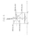
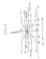
- Fig. 5 shows characteristics of variation of suspension control commands V FL , V FR , V RL and V RR signals having component according to variation of the longitudinal acceleration indicative signal value g x .
- the suspension control commands V FL , V FR , V RL and V RR are derived according to the variation characteristics as shown in Fig. 5 and vary in relation to a neutral value V N . Therefore, while no longitudinal acceleration is exerted on the vehicular body and thus the longitudinal acceleration indicative signal g x is maintained at the neutral value X GN all of the front-left, front-right, rear-left and rear-right suspension control commands F FL , V FR , V RL and V RR are maintained at the neutral value V N .
- the pilot pressures in the pressure control valves 28 are maintained at the neutral pressure P N so that neutral pressure of the control pressure Pc can be supplied from the control port to the working chambers 26d of the hydraulic cylinders 26FL. 26FR, 26RL and 26RR.
- the vehicular height level at orientations of the front-left, front-right, rear-left and rear-right suspension systems 14FL, 14FR, 14RL and 14RR can be maintained within a target height range defined in the vicinity of the target height.
- the longitudinal acceleration sensor 104 is designed to produce the longitudinal acceleration indicative signal g x having a signal value greater than the neutral value V N . Therefore, the longitudinal acceleration data value ⁇ x becomes positive value.
- the front-left and front-right suspension control commands V FL and V FR becomes greater value than the neutral value V N for harder suspension characteristics at the front-left and front-right suspension systems 14FL and 14FR.
- the rear-left and rear-right suspension control commands V RL and V RR becomes smaller value than the neutral value V N for softer suspension characteristics at the rear-left and rear-right suspension systems 14RL and 14RR.
- the front-left and front-right suspension control commands V FL and V FR are increased toward a predetermined maximum value V M ′ in a rate ⁇ 1.
- the rear-left and rear-right suspension control commands V RL and V RR are decreased toward a predetermined minimum value V S in a rate - ⁇ 2.
- is greater than the absolute value of the variation rate
- the magnitude of the acceleration substantially corresponds to the rearward inertia force exerted on the vehicular body, which rearward inertia force causes squat.
- the longitudinal acceleration data value ⁇ x becomes negative value.
- the front-left and front-right suspension control commands V FL and V FR becomes smaller value than the neutral value V N for softer suspension characteristics at the front-left and front-right suspension systems 14FL, and 14FR.
- the rear-left and rear-right suspension control commands V RL and V RR becomes greater value than the neutral value V N for harder suspension characteristics at the rear-left and rear-right suspension systems 14RL and 14RR.
- the front-left and front-right suspension control commands V FL and V FR are decreased toward a predetermined minimum value V S ′ in a rate ⁇ 3.
- the rear-left and rear-right suspension control commands V RL and V RR are increased toward a predetermined minimum value V M in a rate - ⁇ 3.
- is smaller than the absolute value of the variation rate
- Fig. 6 a flowchart of an anti-pitching suspension control routine to be executed by the microprocessor 110.
- the shown routine is programmed as an interrupt routine to be executed at every given timing, e.g. every 20 msec.
- the longitudinal acceleration indicative signal g x is read out, at a step 1002.
- a preset neutral acceleration indicative value X GN is subtracted to derive longitudinal acceleration indicative data ⁇ g x is derived at a step 1004.
- the longitudinal acceleration data ⁇ x is derived at a step 1006.
- the longitudinal acceleration data ⁇ x is set in the memory unit 116 in forms of look-up tables. Therefore, in the practical operation at the step 1006, is table look-up for deriving the longitudinal acceleration data ⁇ x in terms of the longitudinal acceleration indicative data ⁇ g x .
- the anti-pitching front-left, front-right, rear-left and rear right suspension control commands V FL , V FR , V RL and V RR are derived according to the variation characteristics as shown in Fig. 5. Practically, the variation characteristics of the suspension control commands in relation to the longitudinal acceleration data ⁇ x is set in the memory unit 116 in a form of look-up table. Therefore, derivation of the front-left, front-right, rear-left and rear-right suspension control commands V FL , V FR , V RL and V RR is performed by table look-up.
- the shown embodiment takes the way of table look-up for deriving the suspension control command values, it may also be possible to obtain the equivalent command values by arithmetic process as a function of the longitudinal acceleration data ⁇ x.
- the front-left, front-right, rear-left and rear right suspension control commands V FL , V FR , V RL and V RR are output to respectively corresponding driver circuits 122FL. 122FR, 122RL and 122RR via the D/A converters 120FL, 120FR, 120RL and 120RR.
- the driver circuits 122FL, 122FR, 122RL and 122RR then outputs the suspension control signals I FL , I FR , I RL and I RR for adjusting pilot pressure at respective of the pressure control valves 28FL, 28FR, 28RL and 28RR.
- the longitudinal acceleration indicative signal g x are maintained substantially the neutral values Y GN . Therefore, the longitudinal acceleration data ⁇ x derived at the step 1006 in the foregoing routine are maintained substantially zero. Therefore, the anti-rolling suspension control command values V FL , V FR , V RL and V RR are substantially maintained at the neutral command value V N . Therefore, the suspension control signals I FL , I FR , I RL and I RR have the current value I N corresponding to the neutral pressure P N .
- the front-left and front-right suspension control command values V FL and V FR are increased toward the maximum value V M ′ in a rate of ⁇ 1, and the rear-left and rear-right suspension control command values V RL and V RR are decreased toward the minimum value V S in a rate of - ⁇ 2.
- the front suspension systems 14FL and 14FR are hardened by increasing the fluid pressure in the working chambers 26d in the front-left and front-right hydraulic cylinders 26FL and 26FR.
- the rear suspension systems 14RL and 14RR are softened by decreasing the fluid pressure in the working chambers 26d of the rear-left and rear-right hydraulic cylinders 26RL and 26RR. Since the variation rate of the front-left and front-right suspension control command values ⁇ 1 is set at smaller value for setting the maximum value V M ′ smaller than V M and the rear-left and rear-right suspension control command variation rate - ⁇ 2 is greater than normal value for setting the minimum value V S at lower level than the standard level. As a result, anti-pitching effect will be weakened for permitting permissible magnitude of vehicular pitching. At the same time, the vehicular body height may be lowered without causing substantial lift at the rear side of the vehicular body. Therefore, better vehicular brake feeling can be obtained.
- pressure accumulators 34 may not become completely rigid and hold additional capacity. Therefore, the vibration energy having frequency in the vicinity of resonance frequency of the unsprung mass can be successfully absorbed for assuring high level of riding comfort.
- Assurance of riding comfort may be further discussed with reference to Figs. 8 and 9.
- cross sectional area of the piston is A; the internal pressure is P, the piston stroke is x, and reacting force on the road is F.
- the internal volume V is substantially reduced for resulting substantially rigid characteristics.
- the relatively high frequency of vibration is transmission from the road wheel to the vehicular body to cause degradation.
- the internal pressure of the accumulator can be maintained at smaller value for permitting absorption of the relatively high frequency vibration.
- the shown embodiment varies the variation rate of the suspension control command versus variation of the longitudinal acceleration with a common deceleration and acceleration threshold at front and rear suspension systems, it may be possible to use the uniform variation rate with different deceleration and acceleration thresholds or with different fluid pressure limit.
- anti-rolling suspension control in the shown embodiment of the active suspension system, is performed in the variation characteristics of the suspension control commands as illustrated in Figs. 10 and 11.
- the variation characteristics of the front suspension control commands V FL and V FR (Fig. 10) is differentiated from that of the rear suspension control commands V RL and V RR (Fig. 11).
- Fig. 10 shows characteristics of variation of front-left and front-right suspension control commands V FL and V FR having component according to variation of the lateral acceleration indicative signal value g y .
- the suspension control commands V FL and V FR are derived according to the variation characteristics as shown in Fig. 10 and vary in relation to a neutral value V N . Therefore, while no lateral acceleration is exerted on the vehicular body and thus the lateral acceleration indicative signal g y is maintained at the neutral value X GN , both of the front-left and front-right control commands V FL and V FR are maintained at the neutral value V N .
- the pilot pressures in the pressure control valves 28 are maintained at the neutral pressure P N so that neutral pressure of the control pressure Pc can be supplied from the control port to the working chambers 26d of the hydraulic cylinders 26FL and 26FR.
- the vehicular height level at orientations of the front-left and front-right suspension systems 14FL and 14FR can be maintained within a target height range defined in the vicinity of the target height.
- the vehicle steering operation is performed for turning left right-hand lateral acceleration (centrifugal force) is induced.
- the magnitude of the right-hand lateral acceleration substantially corresponds to the rightward centrifugal force exerted on the vehicular body, which right-hand lateral force causes right-hand vehicular rolling.
- the lateral acceleration sensor 102 is designed to produce the lateral acceleration indicative signal g y having a signal value greater than the neutral value V N in response to the right-hand lateral acceleration. Therefore, the lateral acceleration data value ⁇ y becomes positive value.
- the front-right suspension control command V FR becomes greater value than the neutral value V N for harder suspension characteristics at the front-right suspension system 14FR.
- the front-left suspension control command V FL becomes smaller value than the neutral value V N for softer suspension characteristics at the front-left and rear-right suspension systems 14FL.
- the front-right suspension control command V FR is increased in a rate ⁇ 1.
- the front-left suspension control command V FL is decreased in a rate - ⁇ 2.
- the front-right suspension control command V FR is increased toward a predetermined maximum value V M in a rate ⁇ 3 which is smaller than ⁇ 1 .
- the front-left suspension control command V FL is decreased toward a determined minimum value V S in a rate - ⁇ 4 which is also smaller than - ⁇ 2.
- are respectively greater than the absolute value of the variation rate
- the front-left and front-right suspension control commands V FL and V FR are respectively maintained at the minimum and the maximum value V S and V M .
- Fig. 11 shows characteristics of variation of rear-left and rear-right suspension control commands V RL and V RR having component according to variation of the lateral acceleration indicative signal value g y .
- the suspension control commands V RL and V RR are derived according to the variation characteristics as shown in Fig. 10 and vary in relation to a neutral value V N . Therefore, while no lateral acceleration is exerted on the vehicular body and thus the lateral acceleration indicative signal g y is maintained at the neutral value X GN , both of the rear-left and rear-right control commands V RL and V RR are maintained at the neutral value V N .
- the pilot pressures in the pressure control valves 28 are maintained at the neutral pressure P N so that neutral pressure of the control pressure Pc can be supplied from the control port to the working chambers 26d of the hydraulic cylinders 26RL and 26RR.
- the vehicular height level at orientations of the rear-left and rear-right suspension systems 14RL and 14RR can be maintained within a target height range defined in the vicinity of the target height.
- right-hand lateral acceleration (centrifugal force) is induced.
- the magnitude of the right-hand lateral acceleration substantially corresponds to the rightward centrifugal force exerted on the vehicular body, which right-hand lateral force causes right-hand vehicular rolling.
- the lateral acceleration sensor 102 is designed to produce the lateral acceleration indicative signal g y having a signal value greater than the neutral value V N in response to the right-hand lateral acceleration. Therefore, the lateral acceleration data value ⁇ y becomes positive value.
- the rear-right suspension control command V RR becomes greater value than the neutral value V N for harder suspension characteristics at the rear-right suspension system 14RR.
- the rear-left suspension control command V RL becomes smaller value than the neutral value V N for softer suspension characteristics at the front-left and rear-right suspension systems 14RL.
- the rear-right suspension control command V RR is increased in a rate ⁇ 1.
- the rear-left suspension control command V RL is decreased in a rate - ⁇ 2.
- the rear-most suspension control command V RR is increased toward a predetermined maximum value V M ′ in a rate ⁇ 3 which is smaller than ⁇ 1 .
- the rear-left suspension control command V RL is decreased toward a predetermined minimum value V S ′ in a rate - ⁇ 4 which is also smaller than - ⁇ 2.
- are respectively greater than the absolute value of the variation rate
- the rear-left and rear-right suspension control commands V RL , and V RR are respectively maintained at the minimum and the maximum value V S ′ and V M ′.
- the maximum and minimum suspension control command values V M ′ and V S ′ are set at smaller value than the maximum and minimum values V M and V S of the front suspension control commands.
- Fig. 12 a flowchart of an anti-rolling suspension control routine to be executed by the microprocessor 110.
- the shown routine is programmed as an interrupt routine to be executed at every given timing. e.g. every 20 msec.
- the lateral acceleration indicative signal g y is read out, at a step 1102. From the read lateral acceleration indicative signal value g y , a preset neutral acceleration indicative value Y GN is subtracted to derive lateral acceleration indicative data ⁇ g y is derived at a step 1104. Then, on the basis of the lateral acceleration indicative data ⁇ g y , the lateral acceleration data ⁇ y is derived at a step 1106.
- the lateral acceleration data ⁇ y is set in the memory unit 116 in forms of look-up tables. Therefore, in the practical operation at the step 1106, is table look-up for deriving the lateral acceleration data ⁇ y in terms of the lateral acceleration indicative data ⁇ g y .
- the anti-rolling front-left, front-right, rear-left and rear-right suspension control commands V FL , V FR , V RL and V RR are derived according to the variation characteristics as shown in Figs. 10 and 11. Practically, the variation characteristics of the suspension control commands in relation to the lateral acceleration data ⁇ y is set in the memory unit 116 in a form of look-up table. Therefore, derivation of the front-left, front-right, rear-left and rear-right suspension control commands V FL , V FR , V RL and V RR is performed by table look-up.
- the shown embodiment takes the way of table look-up for deriving the suspension control command values, it may also be possible to obtain the equivalent command values by arithmetic process as a function of the lateral acceleration data ⁇ y.
- the front-left, front-right, rear-left and rear-right suspension control commands V FL , V FR , V RL and V RR are output to respectively corresponding driver circuits 122FL, 122FR, 122RL and 122RR via the D/A converters 120FL, 120FR, 120RL and 120RR.
- the driver circuits 122FL, 122FR, 122RL and 122RR then outputs the suspension control signals I FL , I FR , I RL and I RR for adjusting pilot pressure at respective of the pressure control valves 28FL, 28FR, 28RL and 28RR.
- the suspension control signals I FL , I FR , I RL and I RR have the current value I N corresponding to the neutral pressure P N .
- the front-left and front-right suspension control command values V FL and V FR are derived according to the characteristics of Fig. 10
- the rear-left and rear-right suspension control command values V RL and V RR are derived according to the characteristics of Fig. 11.
- the right side suspension systems 14FR and 14RR are hardened by increasing the fluid pressure in the working chambers 26d in the rear-left and rear-right hydraulic cylinders 26FR and 26RR.
- the left side suspension systems 14FL and 14RL are softened by decreasing the fluid pressure in the working chambers 26d of the rear-left and rear-right hydraulic cylinders 26FL and 26RL. Since the variation rate ⁇ 1, ⁇ 3 and ⁇ 1, ⁇ 3 are set at smaller values than ⁇ 2, ⁇ 4 and ⁇ 2, ⁇ 4, anti-rolling effect will be weakened for permitting permissible magnitude of vehicular rolling. At the same time, the vehicular body height may be lowered without causing substantial lift at the rear side of the vehicular body. Therefore, better vehicular brake feeling can be obtained.
- the shown anti-rolling suspension control is further advantageous in comparison with the prior proposed active suspension systems. Namely, in the prior proposed active suspension systems, the fluid pressure in the working chamber is maintained at a predetermined neutral pressure as long as the lateral and/or longitudinal acceleration exerted on the vehicular body is maintained at zero.
- the fluid pressure at left and right suspension systems are adjusted by left and right suspension control commands having equal values but having opposite phases or polarities for hardening suspension systems oriented outside of the curve and softening suspension oriented inside of the curve.
- front and rear suspension control commands having the equal value but opposite phases are supplied to the front and rear suspension system, for suppressing vehicular pitching motion magnitude.
- the fluid pressure in the working chamber is adjusted to a predetermined maximum and minimum level and maintained thereat.
- the predetermined maximum acceleration may be set depending upon the capacity of the hydraulic cylinder, acceptable magnitude of vehicular attitude change, desired critical level of cornering performance and so forth.
- vehicular attitude can be successfully regulated as long as the acceleration exerted on the vehicular body is maintained below the predetermined maximum level.
- the acceleration becomes greater than maximum level, sudden change of vehicular attitude is caused to cause degradation of the riding comfort and driving stability.
- the active suspension system may prevent sudden attitude change ever at the occasion, on which acceleration greater than a predetermined maximum acceleration is exerted.
- the shown embodiment realize this requirement by providing different variation rate at different acceleration magnitude range, so that vehicular rolling is permitted in an acceleration magnitude range in the vicinity of the critical magnitude in a controlled magnitude. This successfully avoid sudden change of the vehicular rolling magnitude when the lateral acceleration increased across the critical magnitude.
- the shown embodiment employs a lateral acceleration sensor for directly monitoring inertia moment exerted on the vehicular body
- the equivalent parameter can be obtained by monitoring a vehicular speed and a steering angular position.
- Such a manner of detection of the laterally exerted inertia moment has been discussed in the Japanese Patent First (unexamined) Publication (Tokkai) Showa 62-293167.
- the disclosure of the above-identified Japanese publication is herein incorporated by reference.
- the shown embodiment performs both of anti-rolling and anti-pitching suspension control
- the invention is of course applicable for suspension system which performs either one of anti-rolling and anti-pitching control.
- the shown embodiment is directed to the control unit comprising a digital processor system for deriving the suspension control command.
- the suspension control command may be derived by amplifying the lateral and/or longitudinal acceleration indicative signal with a predetermined amplifier gain.
- the shown embodiment employs linear variation characteristics of the anti-rolling and anti-pitching components between the criteria, it may be possible to set two or more criteria for defining the variation characteristics of the anti-rolling and /or anti-pitching components. Further to say, the variation characteristics may be set in non-linear fashion, such as a curved characteristics. Therefore, concerning the variation characteristics, it is only essential matter for the present invention to reduce variation rate of the anti-rolling and/or anti-pitching components in greater acceleration range.
- the shown embodiment employs the same acceleration magnitude for setting the criteria for both of anti-rolling control and anti-pitching control, it is of course possible to employ mutually different acceleration magnitude for setting the criteria.
- the algorithm of the invention may be applicable for various types of active suspension systems and also applicable even for passive suspension systems.
Abstract
Description
- The present invention relates generally to a suspension control system for controlling vehicular suspension characteristics for achieving both of riding comfort and driving stability. More specifically, the invention relates to a suspension control system, particularly applicable for an active suspension system, which suspension control system performs height adjustment for assuring vehicular driving stability at particular vehicle driving condition inducing inertia force affecting vehicular attitude.
- In the modern automotive technologies, active suspension systems have been introduced for better vehicular height and vehicular attitude regulating potential. Such recently developed or proposed active suspension systems generally performs vehicular height regulation and vehicular attitude regulation, e.g. anti-pitching and anti-rolling control.
- Japanese Patent First (unexamined) Publications(Tokkai) Showa 62-295714 and 63-235112 disclose typical constructions of active suspension systems. The active suspension system disclosed in the former publication is designed to perform anti-rolling suspension control on the basis of lateral acceleration exerted on the vehicular body. The shown system adjusts fluid pressure in working chambers in a hydraulic cylinder for adjusting damping force resisting against rolling moment and whereby suppressing vehicular rolling. On the other hand, the later publication discloses an active suspension system which performs anti-pitching control on the basis of longitudinal acceleration exerted on the vehicular body. The system also adjusts the fluid pressure in the working chambers in the hydraulic cylinders so as to suppress vehicular pitching motion. The later publication further discloses use of variable gains for controlling front and rear suspension systems, with which gains the longitudinal acceleration indicative signal is amplified to derive front and rear suspension control commands. The variable gain provided in the later publication is expected to provided higher precision and optimum suspension control performance.
- In such prior proposed active suspension systems, the fluid pressure in the working chamber is maintained at a predetermined neutral pressure as long as the lateral and/or longitudinal acceleration exerted on the vehicular body is maintained at zero. When vehicle rolls, the fluid pressure at left and right suspension systems are adjusted by left and right suspension control commands having equal values but having opposite phases or polarities for hardening suspension systems oriented outside of the curve and softening suspension oriented inside of the curve. Similarly, when vehicular pitching is caused, front and rear suspension control commands having the equal value but opposite phases are supplied to the front and rear suspension system, for suppressing vehicular pitching motion magnitude.
- Theses prior proposed active suspension systems are effective for regulating vehicular height level substantially at a target height or within a predetermined target height range set about the target height and for regulating vehicular attitude. On the other hand, vehicular drivers have tendency of expecting vehicular attitude change causing lowering of vehicular height at one side of the vehicular body during acceleration, deceleration and cornering. Furthermore, the drivers may feel higher stability if the vehicular height is lowered when inertia force causing vehicular rolling and/or pitching is exerted on the vehicular body. In contrast to this, the active suspension system normally adjusts the vehicular height at least within the target height range even when the inertia force in longitudinal or lateral direction is exerted. Therefore, despite of the fact that the vehicular driving stability is assured by adjustment of suspension characteristics at each of individual suspension systems, the drivers might feel that the vehicular height is excessively high to bring instability of the vehicle. This may degrade drive feeling of the vehicle.
- Therefore, it is an object of the present invention to provide a suspension control system which can improves vehicular behavior in response to an inertia force for better drive feeling.
- In order to accomplish aforementioned and other objects, a suspension control system, according to the present invention, according to the present invention, includes a suspension system which is disposed between a vehicular body and each road wheel and variable of damping characteristics. The suspension system is associated with means for adjusting damping characteristics according to a suspension control command. The suspension control system also includes a sensor means for monitoring inertia force exerted on the vehicular body, which inertia force affects for vehicular attitude to cause attitude change. A control unit receives the output of the sensor means for deriving the suspension control command for regulating vehicular height and vehicular attitude. The control unit is designed to detect a predetermined particular vehicle driving condition on the basis of the sensor output for deriving the suspension control command for adjusting vehicular height lower level than a normal height level.
- According to one aspect of the invention, a suspension control system for an automotive vehicle comprises:
a plurality of suspension systems, each disposed between a vehicular body and a road wheel for damping relative displacement therebetween,
damping characteristics adjusting means associated with each suspension system for controlling damping characteristics of the suspension system according to a suspension control command values;
sensor means for monitoring inertia force induced on the vehicular body for affecting on a vehicular attitude, said sensor means producing a sensor signal representative of the monitored inertia force;
control means for performing control operation on the basis of said sensor signal for deriving said suspension control command for regulating vehicular height at a predetermined standard height range and regulating vehicular attitude, said control means detecting a predetermined particular vehicle driving condition on the basis of said sensor signal for switching control mode for adjusting vehicular height at a level lower than said standard height range with controlled magnitude of vehicular attitude change. - Preferably, the control means derives a hardening suspension control command for suspension system at which relative displacement between said vehicular body and said road wheel is caused for reducing the relative distance between, and a softening suspension control command for suspension systems at which relative displacement between said vehicular body and said road wheel is caused for increasing the relative distance therebetween, said control means being responsive to said particular vehicle driving condition to reducing hardening magnitude for said hardening suspension control command and increasing softening magnitude for said softening suspension control command. In such case, it is preferred that the control means performs anti-pitching suspension control for lowering the vehicular height in response to longitudinally exerted inertia force. The control means is responsive to a backward inertial force exerted on the vehicular body for lowering the vehicular height below said standard height range.
- In the alternative, the control means performs anti-rolling suspension control for lowering the vehicular height in response to a laterally exerted inertia force. The control means may vary a variation rate of said suspension control command versus variation of said sensor signal value so that said variation rate is smaller at least in a sensor signal value range in the vicinity of said first and second values. In this case, the sensor signal valve may be variable across said first and second values and further across a third value set between said first and second values and corresponding to the vehicular state where the inetia force exerted on the vehicular body is zero, and said variation rate of said suspension control command in the sensor signal range in the vicinity of said third value is greater than said variation rate in the vicinity of said first and second values. The suspension control command may vary according to variation of said sensor signal value at a first variation rate in a sensor signal value range between said third value and a fourth value greater than said third value and smaller than said first value, and a second variation rate in a sensor signal value range between said fourth value and said first value. The suspension control command may also vary according to variation of said sensor signal value at a third variation rate in a sensor signal value range between said third value and a fifth value smaller than said third value and greater than said second value, and a fourth variation rate in a sensor signal value range between said fifth value and said second value.
- In the alternative, the variation rate is continuously varied so that greater variation rate is obtained in the vicinity of said third value and smaller variation rate is obtained in the vicinity of said first and second values. Furthermore, the said suspension control command may be provided for one side of the vehicular body for hardening suspension control and for the other side of the vehicular body for softening suspension control for regulating vehicular attitude, said sensor signal valve is variable across said first and second values and further across a third value set between said first and second values and corresponding to the vehicular state where the inertia force exerted on the vehicular body is zero, and said variation rate of said hardening suspension control command in the sensor signal range in a first sensor signal value range defined in the vicinity of said third value is greater than said variation rate in a second sensor signal value range defined in the vicinity of said first value, and said variation rate of said softening suspension control command in a third range defined in the vicinity of said third sensor signal value value is greater than the variation rate in a fourth sensor signal value range defined in the vicinity of said second value. In such case, the fourth sensor signal value range may be smaller than said second sensor signal value range.
- The present invention will be understood more fully from the detailed description given herebelow and from the accompanying drawings of the preferred embodiment of the invention, which, however, should not be taken to limit the invention to the specific embodiments but are for explanation and understanding only.
- In the drawings:
- Fig. 1 is a diagrammatic illustration of the preferred embodiment of an active suspension system according to the present invention;
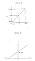
- Fig. 2 is a chart showing variation of control pressure level Pc relative to current level of a suspension control signal i;
- Fig. 3 is a chart showing variation of output level of acceleration sensor in relation to acceleration exerted on the vehicular body;
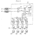
- Fig. 4 is a block diagram of a suspension control system employed in the shown embodiment of the active suspension system according to the invention;
- Fig. 5 is a chart showing variation of an anti-pitching suspension control command value versus magnitude of longitudinal acceleration exerted on a vehicular body;
- Fig. 6 is a flowchart showing routine for anti-pitching suspension control performed in the suspension control system of Fig. 4;
- Fig. 7 is a chart showing variation fluid pressure in a working chamber in the anti-pitching suspension control versus magnitude of longitudinal acceleration exerted on the vehicular body;
- Fig. 8 is an explanatory illustration of a pressure accumulator;
- Fig. 9 is a chart showing variation of internal volume of the pressure accumulator relative to variation of internal pressure thereof;
- Fig. 10 is a chart showing variation of front-left and front-right suspension control commands in relation to lateral acceleration magnitude;
- Fig. 11 is a chart showing variation of rear-left and rear-right suspension control commands in relation to lateral acceleration magnitude;
- Fig. 12 is a flowchart of an anti-rolling suspension control to be executed by the suspension control system of Fig. 4; and
- Fig. 13 is a chart showing variation of fluid pressure in the working chamber in relation to variation of the lateral acceleration.
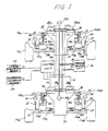
- Referring now to the drawings, particularly to Fig. 1, the preferred embodiment of an active suspension system, according to the present invention, is designed to generally perform suspension control for regulating vehicular height level and vehicular attitude by suppressing relative displacement between a
vehicular body 10 and suspension members 12FL, 12FR, 12RL and 12RR of front-left, front-right, rear-left and rear-right suspension mechanism 14FL, 14FAR, 14AIL and 14RR and rotatably supporting front-left, front-right, rear-left and rear-right wheels 11FL, 11FR, 11RL and 11RR. The suspension mechanism as generally referred to will be hereafter represented by the reference numeral "14" Respective front-left, front-right, rear-left and rear-right suspension mechanisms 14FL, 14FAR, 14AIL and 14RR have hydraulic cylinders 26FL, 26FAR, 26AIL and 26RR which will be represented by the reference numeral "26" as generally referred to. - Each of the hydraulic cylinder 26 is disposed between the
vehicular body 10 and the suspension member 12FL, 12FR, 12RL and 12RR to produce a damping force for suppressing relative displacement between the vehicular body and the suspension member. The hydraulic cylinder 26 generally comprises an essentially enclosed cylindrical cylinder body 26a defining therein an enclosed chamber. A thrustingpiston 26c is thrustingly and slidably disposed within the enclosed chamber of the hydraulic cylinder 26 for defining in the latter a workingchamber 26d. Thepiston 26c is connected to the associated one of suspension member 12 via a piston rod 26b. Asuspension coil spring 25 are also provided in respective of suspension mechanisms. However, in contrast to the normal or ordinary suspension systems, the suspension coil spring to be employed in the shown type of the suspension system is not required a resilient force in a magnitude required in the ordinary suspension system and only required the resilient force necessary for maintaining the vehicular body about the suspension member. - The working
chamber 26d of the hydraulic cylinder 26 is connected one of pressure control valves 28FL, 28FAR, 28AIL and 28RR via apressure control line 38. The pressure control valve 28FL, 28FAR, 28AIL and 28RR will be hereafter represented by the reference numeral "28" as generally referred to. The pressure control valve 28 has a control port 28c communicated with the workingchamber 26d via thepressure control line 38. The pressure control valve 28 also has an inlet port 28s and a drain port 28r. The inlet port 28s of the pressure control valve 28 is connected to o apressure source unit 16 via asupply line 35, and the drain port 28r thereof is communicated with adrain line 37. The pressure control valve 28 incorporates aproportioning solenoid 26e for adjusting valve position according to magnitude of suspension control signal IFL, IFR, IRL and IRR supplied from thecontrol unit 100. The suspension control signal IFL, IFR, IRL and [E]I[-]RR are current signal having a variable current value representative of commanding pressure in the working chamber. A branch circuit is provided for connecting the workingchamber 26d to apressure accumulator 34 via aflow path 33 and a flow restricting means, such as anorifice 32. Thispressure accumulator 34 may be hereafter referred to as "low pressure accumulator". Anotherpressure accumulators 20F and 20R are provided in thesupply line 35 for accumulating the excessive pressure generated in thepressure source unit 16. - The pressure control valves 28 comprise, though it is not clearly shown in Fig. 1, electrically or electromagnetically operable actuators, such as a proportioning solenoids. The hydraulic cylinder 26 and the pressure control valve 28 may be of any suitable constructions for adjusting damping characteristics with sufficiently high response. Typical constructions of the hydraulic cylinder 26 and the pressure control valve 28 have been disclosed in the following prior applications or publications:
U. S. Patent Application Serial No. 052,934, filed on May 22, 1989;
U. S. Patent Application Serial No. 059,888, filed on June 9, 1987, corresponding European Patent Application has been published as First Publication No. 02 49 209;
U. S. Patent Application Serial No. 060,856, filed on June 12, 1987, corresponding European Patent Application has been published as First Publication No. 02 49 227;
U. S. Patent Application Serial No. 060,909, filed on June 12, 1987;
U. S. Patent Application Serial No. 060,911, filed on June 12, 1987;
U. S. Patent Application Serial No. 176,24, filed on March 31, 1988, the corresponding European Patent Application has been published as First Publication No. 02 85 153;
U. S. Patent Application Serial No. 178,066, filed on April 5, 1988, the corresponding European Patent Application has been published as First Publication No. 02 86 072;
U. S. Patent Application Serial No. 167,835, filed on March 4, 1988;
U. S. Patent Application Serial No. 244,008, filed on September 14, 1988;
U. S. Patent Application Serial No. 255,560, filed on October 11, 1988;
U. S. Patent Application Serial No. 266,763, filed on November 3, 1988;
U. S. Patent Application Serial No. 261,870, filed on October 25, 1988;
U. S. Patent Application Serial No. 263,764, filed on October 28, 1988;
U. S. Patent Application Serial No. 277,376, filed on November 29, 1988;
U. S. Patent Application Serial No. 303,338, filed on January 26, 1989;
U. S. Patent Application Serial No. 310,130, filed on March 22, 1989;
U. S. Patent Application Serial No. 327,460, filed on March 22, 1989;
U. S. Patent Application Serial No. 303,339, filed on January 26, 1989;
U. S. Patent Application Serial No. 331,602, filed on March 31, 1989;
U. S. Patent Application Serial No. 331,653, filed on March 31, 1989;
U. S. Patent Application Serial No. 364,477, filed on June 12, 1989;
U. S. Patent Application Serial No. 365,468, filed on June 12, 1989; - The disclosures of the foregoing co-pending applications are herein incorporated by reference for the sake of disclosure.
- The pressure control valve 28 employed in the shown embodiment incorporates a proportioning solenoid 28e for adjusting valve position and thus adjusts control pressure Pc to be supplied to the working
chamber 26d of the associated one of the hydraulic cylinder 26. In practice, the pressure control valve 28 employed in the shown embodiment is designed as pilot operated valve, in which the pilot pressure is adjusted by the position of the proportioning solenoid. - For adjusting control pressure at the control port 28c by adjusting the position of the proportioning solenoid 28e, a suspension control signal which is in a form of a current signal having a current variable depending upon the command value. The suspension control command value is derived by a
control unit 100. In order to perform, height regulation and attitude regulation for the vehicular body, thecontrol unit 100 is connected to a plurality of sensors for monitoring various suspension control parameters. Parameters for performing suspension control and data processing for deriving the suspension control command values have been discussed in various co-pending applications set forth above. Amongst, the following disclosure may be concentrated for anti-rolling and anti-pitching suspension control which may be combined with any other logic of suspension control. - Though the suspension control may perform various control logic, the following discussion will be concentrated to anti-rolling and anti-pitching control to be performed by the
control unit 100. In order to do this, thecontrol unit 100 is connected to alateral acceleration sensor 102 and alongitudinal acceleration sensor 104. Thelateral acceleration sensor 102 is designed to produce a lateral acceleration indicative signal gy representative of a magnitude of lateral acceleration exerted on thevehicular body 10. As can be appreciated, the lateral acceleration exerted on the vehicular body represents inertia force transverse to the vehicular axis. Therefore, the lateral acceleration indicative signal gy generated by thelateral acceleration sensor 102 in fact represents magnitude of inertia force, i.e. centrifugal force, induced at turning or cornering of the vehicle. For enabling this, thelateral acceleration sensor 102 may be mounted on an appropriate position of the vehicular body. Preferred orientation of the lateral acceleration sensor has been discussed in the undermentioned co-pending applications. Furthermore, as discussed in the co-pending U. S. Patent Application, entitled " ", filed on which corresponds to Japanese Patent Application No. , filed on , the lateral acceleration sensor is not necessarily single but can be employed in plural for optimizing detection of the lateral acceleration with higher response. Preferred arrangement of a plurality of lateral acceleration sensors and suspension control operation utilizing the same will be herein incorporated by reference. - On the other hand, the
longitudinal acceleration sensor 104 is designed to produce a longitudinal acceleration indicative signal gx representative of the longitudinal acceleration exerted on the vehicular body. Similarly to the foregoing, the longitudinal acceleration represents inertia force in a direction parallel to the vehicular axis, induced during acceleration and deceleration for causing squat and nose-dive. Therefore, the longitudinal acceleration indicative signal gx produced by thelongitudinal acceleration sensor 104 represents the magnitude of longitudinally exerted inertia force on the vehicular body. - In the meanwhile, one example of the acceleration sensor which can be used as the lateral and longitudinal acceleration sensor has been illustrated in the co-pending U. S. Patent Application, entitled " ", filed on , which corresponds to the Japanese Patent Application No. , filed on . The disclosure concerning the acceleration sensor construction and operation are herein incorporated by reference.
- Both of the lateral acceleration indicative signal gy and the longitudinal acceleration indicative signal gx are analog signals having voltage level variable depending upon the magnitude of the lateral and longitudinal acceleration exerted on the vehicular body.
- The
control unit 100 comprises analog-to-digital (A/D) converters 106Y and 106X to convert the analog form lateral and longitudinal acceleration indicative signals gy and gx into digital signals. The A/D converters 106Y and 106X feed digital form lateral and longitudinal acceleration indicative signals gy and gx to amicroprocessor 110 which comprises an input/output interface 112, anarithmetic circuit 114 and amemory unit 116. Themicroprocessor 110 processes the lateral and longitudinal acceleration indicative signals gy and gx to derive lateral and longitudinal acceleration data GY and GX and produce front-left, front-right-rear-left and rear-right suspension control commands VFL, VFR, VRL and VRR in forms of voltage signals having voltage level representative of required magnitude of control pressure Pc to be supplied from the pressure control valves 28FL. 28FR, 28RL and 28RR to respectively corresponding workingchambers 26d of the hydraulic cylinders 26FL, 26FR, 26RL and 26RR. In practice, the suspension control commands VFL, VFR, VRL and VRR have voltage levels representative of the pressure off-set of the control pressure Pc from a predetermined neutral pressure PN. The front-left, front-right-rear-left and rear-right suspension control commands VFL, VFR, VRL and VRR are converted into analog signals by digital-to-analog (D/A) converters 120FL, 120FR, 120RL and 120RR. The D/A converted front-left, front-right-rear-left and rear-right suspension control commands VFL, VFR, VRL and VRR are supplied to driver circuits 122FL, 122FR, 122RL and 122RL. The driver circuits 122FL, 122FR, 122RL and 122RR comprise current signal generator, such as floating type constant current generator,for producing current signal form front-left, front-right-rear-left and rear-right suspension control signals IFL, IFR, IRL and IRR having current value variable corresponding to the suspension control command values VFL, VFR, VRL and VRR. The suspension control signals IFL, IFR, IRL and IRR are fed to proportioning solenoids of respectively corresponding pressure control valves 28FL, 28RL, 28RL and 28RR for controlling pilot pressure therein and whereby controlling the control pressure Pc to be supplied to the corresponding workingchambers 26d. - As shown in Fig. 2, the control pressure Pc to be supplied from the pressure control valve 28 to the working
chamber 26d via the control line 28 is variable between a predetermined maximum pressure Pmax and a predetermined minimum pressure Pmin across the predetermined neutral pressure PN while the suspension control signal varies its current level between a predetermined maximum value Imax and a predetermined minimum value Imin. The neutral pressure PN of the control pressure Pc is produced in response to the suspension control signal having a value IN. - On the other hand, as seen from Fig. 3, the output levels of the lateral and
longitudinal acceleration sensors longitudinal acceleration sensor lateral acceleration sensor 102 increases the output level fromthe neutral level YGN in response to increasing lateral acceleration directed right. On the other hand, the output level of thelateral acceleration sensor 102 decrease from the neutral level YGN in response to increasing lateral acceleration directed left. Similarly, thelongitudinal acceleration sensor 104 increases the output level in response to rearward acceleration, i.e. deceleration for the vehicle and decreases in response to forward acceleration, i.e. acceleration of the vehicle. - In the practical construction of the active suspension system, respective of the suspension control command values are derived with incorporating a neutral pressure indicative component VN, an anti-pitching control component VPi (i: FL, FR, RL and RR) and an anti-rolling control component VRi. Namely, respective of the front- left, front-right, rear-left and rear-right suspension control commands VFL, VFR, VRL and VRR can be expressed by:
VFL = VN - VRFL + VPFL
VFR = VN + VRFR + VPFR
VRL = VN - VRRL - VPRL
VRR = VN + VRRR - VRRR - Though it can be naturally appreciated that it is preferred to perform both of anti-pitching control and anti-rolling control, it is of course possible to facilitate the suspension control for performing either one of anti-pitching and anti-rolling control. For the sake of disclosure and facilitating better understanding, the following discussion will be given for the anti-pitching suspension control and the anti-rolling suspension control independently of the other.
- Fig. 5 shows characteristics of variation of suspension control commands VFL, VFR, VRL and VRR signals having component according to variation of the longitudinal acceleration indicative signal value gx. The suspension control commands VFL, VFR, VRL and VRR are derived according to the variation characteristics as shown in Fig. 5 and vary in relation to a neutral value VN. Therefore, while no longitudinal acceleration is exerted on the vehicular body and thus the longitudinal acceleration indicative signal gx is maintained at the neutral value XGN all of the front-left, front-right, rear-left and rear-right suspension control commands FFL, VFR, VRL and VRR are maintained at the neutral value VN. Therefore, the pilot pressures in the pressure control valves 28 are maintained at the neutral pressure PN so that neutral pressure of the control pressure Pc can be supplied from the control port to the working
chambers 26d of the hydraulic cylinders 26FL. 26FR, 26RL and 26RR. As a result, the vehicular height level at orientations of the front-left, front-right, rear-left and rear-right suspension systems 14FL, 14FR, 14RL and 14RR can be maintained within a target height range defined in the vicinity of the target height. - On the other hand, when the vehicle is decelerated, backward acceleration (deceleration) is induced. The magnitude of the deceleration substantially corresponds to the forward inertia force exerted on the vehicular body, which forward inertia force causes nose-dive. As set forth, since the
longitudinal acceleration sensor 104 is designed to produce the longitudinal acceleration indicative signal gx having a signal value greater than the neutral value VN. Therefore, the longitudinal acceleration data value αx becomes positive value. In such case, the front-left and front-right suspension control commands VFL and VFR becomes greater value than the neutral value VN for harder suspension characteristics at the front-left and front-right suspension systems 14FL and 14FR. On the other hand, the rear-left and rear-right suspension control commands VRL and VRR becomes smaller value than the neutral value VN for softer suspension characteristics at the rear-left and rear-right suspension systems 14RL and 14RR. - When the longitudinal acceleration data αx is greater then zero and smaller than or equal to a
deceleration threshold αx ₁, e.g. 0.5G, the front-left and front-right suspension control commands VFL and VFR are increased toward a predetermined maximum value VM′ in arate α ₁. On the other hand, the rear-left and rear-right suspension control commands VRL and VRR are decreased toward a predetermined minimum value VS in a rate -α ₂. As can be seen, the absolute value of variation rate |α ₂ | is greater than the absolute value of the variation rate |α ₁|. On the other hand, when the longitudinal acceleration data αx is greater than thedeceleration threshold αx ₁, the front-left and front-right suspension control commands VFL and VFR are maintained at the maximum value VM′, and the rear-left and rear-right suspension control commands VRL and VRR are maintained at the minimum value VS. - When the vehicle is accelerated, forward acceleration is induced. The magnitude of the acceleration substantially corresponds to the rearward inertia force exerted on the vehicular body, which rearward inertia force causes squat. The longitudinal acceleration data value αx becomes negative value. In such case, the front-left and front-right suspension control commands VFL and VFR becomes smaller value than the neutral value VN for softer suspension characteristics at the front-left and front-right suspension systems 14FL, and 14FR. On the other hand, the rear-left and rear-right suspension control commands VRL and VRR becomes greater value than the neutral value VN for harder suspension characteristics at the rear-left and rear-right suspension systems 14RL and 14RR.
- When the negative value of the longitudinal acceleration data -αx is smaller than zero and greater than or equal to an acceleration threshold -
αx ₁, e.g.- 0.5G, the front-left and front-right suspension control commands VFL and VFR are decreased toward a predetermined minimum value VS′ in a rate α ₃. On the other hand, the rear-left and rear-right suspension control commands VRL and VRR are increased toward a predetermined minimum value VM in a rate -α ₃. As can be seen, the absolute value of variation rate |α ₃| is smaller than the absolute value of the variation rate |α ₂| and greater than the absolute value of the variation rate |α ₁|. On the other hand, when the longitudinal acceleration data -αx is smaller than the deceleration threshold -αx ₁, the front-left and front-right suspension control commands VFL and VFR are maintained at the minimum value VS′, and the rear-left and rear-right suspension control commands VRL and VRRmaintained at the maximum value VM. - The practical control operation to be taken place by the
control unit 100 will be discussed with reference to Fig. 6, in which is shown a flowchart of an anti-pitching suspension control routine to be executed by themicroprocessor 110. The shown routine is programmed as an interrupt routine to be executed at every given timing, e.g. every 20 msec. - Immediately after starting execution, the longitudinal acceleration indicative signal gx is read out, at a
step 1002. From the rear longitudinal acceleration indicative signal value gx, a preset neutral acceleration indicative value XGN is subtracted to derive longitudinal acceleration indicative data Δg x is derived at astep 1004. Then, on the basis of the longitudinal acceleration indicative data Δg x, the longitudinal acceleration data αx is derived at astep 1006. In practice, the longitudinal acceleration data αx is set in thememory unit 116 in forms of look-up tables. Therefore, in the practical operation at thestep 1006, is table look-up for deriving the longitudinal acceleration data αx in terms of the longitudinal acceleration indicative data Δg x. - At at
step 1008, the anti-pitching front-left, front-right, rear-left and rear right suspension control commands VFL, VFR, VRL and VRR are derived according to the variation characteristics as shown in Fig. 5. Practically, the variation characteristics of the suspension control commands in relation to the longitudinal acceleration data αx is set in thememory unit 116 in a form of look-up table. Therefore, derivation of the front-left, front-right, rear-left and rear-right suspension control commands VFL, VFR, VRL and VRR is performed by table look-up. However, the shown embodiment takes the way of table look-up for deriving the suspension control command values, it may also be possible to obtain the equivalent command values by arithmetic process as a function of the longitudinal acceleration data αx. Thereafter, at astep 1010, the front-left, front-right, rear-left and rear right suspension control commands VFL, VFR, VRL and VRR are output to respectively corresponding driver circuits 122FL. 122FR, 122RL and 122RR via the D/A converters 120FL, 120FR, 120RL and 120RR. The driver circuits 122FL, 122FR, 122RL and 122RR then outputs the suspension control signals IFL, IFR, IRL and IRR for adjusting pilot pressure at respective of the pressure control valves 28FL, 28FR, 28RL and 28RR. - While the vehicle travels smooth straight road at constant speed, vehicular pitching will never induced. Therefore, the the longitudinal acceleration indicative signal gx are maintained substantially the neutral values YGN. Therefore, the longitudinal acceleration data αx derived at the
step 1006 in the foregoing routine are maintained substantially zero. Therefore, the anti-rolling suspension control command values VFL, VFR, VRL and VRR are substantially maintained at the neutral command value VN. Therefore, the suspension control signals IFL, IFR, IRL and IRR have the current value IN corresponding to the neutral pressure PN. - On the other hand, when vehicular brake is applied for deceleration, the positive value of the longitudinal acceleration αx is increased according to increasing of magnitude of deceleration. Therefore, the front-left and front-right suspension control command values VFL and VFR are increased toward the maximum value VM′ in a rate of
α ₁, and the rear-left and rear-right suspension control command values VRL and VRR are decreased toward the minimum value VS in a rate of -α ₂. By this, the front suspension systems 14FL and 14FR are hardened by increasing the fluid pressure in the workingchambers 26d in the front-left and front-right hydraulic cylinders 26FL and 26FR. On the other hand, the rear suspension systems 14RL and 14RR are softened by decreasing the fluid pressure in the workingchambers 26d of the rear-left and rear-right hydraulic cylinders 26RL and 26RR. Since the variation rate of the front-left and front-right suspension control command values α ₁ is set at smaller value for setting the maximum value VM′ smaller than VM and the rear-left and rear-right suspension control command variation rate -α ₂ is greater than normal value for setting the minimum value VS at lower level than the standard level. As a result, anti-pitching effect will be weakened for permitting permissible magnitude of vehicular pitching. At the same time, the vehicular body height may be lowered without causing substantial lift at the rear side of the vehicular body. Therefore, better vehicular brake feeling can be obtained. - Furthermore, in the shown embodiment, since the increasing rate of the fluid pressure in the working chamber of the front suspension system is set smaller than normal increasing rate during deceleration,
pressure accumulators 34 may not become completely rigid and hold additional capacity. Therefore, the vibration energy having frequency in the vicinity of resonance frequency of the unsprung mass can be successfully absorbed for assuring high level of riding comfort. - Assurance of riding comfort may be further discussed with reference to Figs. 8 and 9. In the model of the cylinder in Fig. 8, it is assumed that cross sectional area of the piston is A; the internal pressure is P, the piston stroke is x, and reacting force on the road is F. Then, the spring constant of the model cylinder can be expressed by:
K = ΔF/Δx
where F = P x A; ΔF = ΔP x A; ΔV = A x Δx; and Δx = ΔV/A
Therefore, the foregoing equation can be modified as:
K = ΔF/Δx
= (ΔP x A)/(ΔV/A)
= A² x (ΔP/ΔV)
As can be appreciated herefrom, the spring constant is proportional to ΔP/ΔV. Therefore, when (P x V) is constant, the internal pressure b at the deceleration becomes higher than that a in the constant speed cruising. - Consequently, when the fluid pressure at the front suspension systems are adjusted to the standard maximum pressure, the internal volume V is substantially reduced for resulting substantially rigid characteristics. In such case, the relatively high frequency of vibration is transmission from the road wheel to the vehicular body to cause degradation. In contrast to this, since the shown embodiment limits the maximum pressure at lower level than the standard maximum pressure, the internal pressure of the accumulator can be maintained at smaller value for permitting absorption of the relatively high frequency vibration.
- It should be appreciated though the shown embodiment varies the variation rate of the suspension control command versus variation of the longitudinal acceleration with a common deceleration and acceleration threshold at front and rear suspension systems, it may be possible to use the uniform variation rate with different deceleration and acceleration thresholds or with different fluid pressure limit.
- On the other hand, anti-rolling suspension control, in the shown embodiment of the active suspension system, is performed in the variation characteristics of the suspension control commands as illustrated in Figs. 10 and 11. As can be seen from Figs. 10 and 11, the variation characteristics of the front suspension control commands VFL and VFR (Fig. 10) is differentiated from that of the rear suspension control commands VRL and VRR (Fig. 11).
- Fig. 10 shows characteristics of variation of front-left and front-right suspension control commands VFL and VFR having component according to variation of the lateral acceleration indicative signal value gy. The suspension control commands VFL and VFR are derived according to the variation characteristics as shown in Fig. 10 and vary in relation to a neutral value VN. Therefore, while no lateral acceleration is exerted on the vehicular body and thus the lateral acceleration indicative signal gy is maintained at the neutral value XGN, both of the front-left and front-right control commands VFL and VFR are maintained at the neutral value VN. Therefore, the pilot pressures in the pressure control valves 28 are maintained at the neutral pressure PN so that neutral pressure of the control pressure Pc can be supplied from the control port to the working
chambers 26d of the hydraulic cylinders 26FL and 26FR. As a result, the vehicular height level at orientations of the front-left and front-right suspension systems 14FL and 14FR can be maintained within a target height range defined in the vicinity of the target height. - On the other hand, when the vehicle steering operation is performed for turning left right-hand lateral acceleration (centrifugal force) is induced. The magnitude of the right-hand lateral acceleration substantially corresponds to the rightward centrifugal force exerted on the vehicular body, which right-hand lateral force causes right-hand vehicular rolling. As set forth, since the
lateral acceleration sensor 102 is designed to produce the lateral acceleration indicative signal gy having a signal value greater than the neutral value VN in response to the right-hand lateral acceleration. Therefore, the lateral acceleration data value αy becomes positive value. In such case, the front-right suspension control command VFR becomes greater value than the neutral value VN for harder suspension characteristics at the front-right suspension system 14FR. On the other hand, the front-left suspension control command VFL becomes smaller value than the neutral value VN for softer suspension characteristics at the front-left and rear-right suspension systems 14FL. - When the lateral acceleration data αy is greater then zero and smaller than or equal to a first lateral
acceleration threshold αy ₁, e.g. 0.3G, the front-right suspension control command VFR is increased in arate β ₁. On the other hand, the front-left suspension control command VFL is decreased in a rate -β ₂. On the other hand, when the lateral acceleration data value αy is greater thanαy ₁ but smaller than or equal to a second lateralacceleration threshold αy ₂, e.g. 0.5G, the front-right suspension control command VFR is increased toward a predetermined maximum value VM in a rate β ₃ which is smaller thanβ ₁ . On the other hand, the front-left suspension control command VFL is decreased toward a determined minimum value VS in a rate -β ₄ which is also smaller than -β ₂. - As can be seen, the absolute value of variation rate |
β ₂| andβ ₂| are respectively greater than the absolute value of the variation rate |β ₁| and . On the other hand, when the lateral acceleration data αy is greater than the second lateralacceleration threshold αy ₂, the front-left and front-right suspension control commands VFL and VFR are respectively maintained at the minimum and the maximum value VS and VM. - Similarly, Fig. 11 shows characteristics of variation of rear-left and rear-right suspension control commands VRL and VRR having component according to variation of the lateral acceleration indicative signal value gy. The suspension control commands VRL and VRR are derived according to the variation characteristics as shown in Fig. 10 and vary in relation to a neutral value VN. Therefore, while no lateral acceleration is exerted on the vehicular body and thus the lateral acceleration indicative signal gy is maintained at the neutral value XGN, both of the rear-left and rear-right control commands VRL and VRR are maintained at the neutral value VN. Therefore, the pilot pressures in the pressure control valves 28 are maintained at the neutral pressure PN so that neutral pressure of the control pressure Pc can be supplied from the control port to the working
chambers 26d of the hydraulic cylinders 26RL and 26RR. As a result, the vehicular height level at orientations of the rear-left and rear-right suspension systems 14RL and 14RR can be maintained within a target height range defined in the vicinity of the target height. - On the other hand, when the vehicle steering operation is performed for turning left, right-hand lateral acceleration (centrifugal force) is induced. The magnitude of the right-hand lateral acceleration substantially corresponds to the rightward centrifugal force exerted on the vehicular body, which right-hand lateral force causes right-hand vehicular rolling. As set forth, since the
lateral acceleration sensor 102 is designed to produce the lateral acceleration indicative signal gy having a signal value greater than the neutral value VN in response to the right-hand lateral acceleration. Therefore, the lateral acceleration data value αy becomes positive value. In such case, the rear-right suspension control command VRR becomes greater value than the neutral value VN for harder suspension characteristics at the rear-right suspension system 14RR. On the other hand, the rear-left suspension control command VRL becomes smaller value than the neutral value VN for softer suspension characteristics at the front-left and rear-right suspension systems 14RL. - When the lateral acceleration data αy is greater then zero and smaller than or equal to a first lateral
acceleration threshold αy ₁, e.g. 0.3G, the rear-right suspension control command VRR is increased in arate γ ₁. On the other hand, the rear-left suspension control command VRL is decreased in a rate -γ ₂. On the other hand, when the lateral acceleration data value αy is greater thanαy ₁ but smaller than or equal to a second lateralacceleration threshold αy ₂, e.g. 0.5G, the rear-right suspension control command VRR is increased toward a predetermined maximum value VM′ in a rate γ ₃ which is smaller thanγ ₁ . On the other hand, the rear-left suspension control command VRL is decreased toward a predetermined minimum value VS′ in a rate -γ ₄ which is also smaller than -γ ₂. - As can be seen, the absolute value of variation rate |
γ ₂| andγ ₂| are respectively greater than the absolute value of the variation rate |γ ₁| and . On the other hand, when the lateral acceleration data αy is greater than the second lateralacceleration threshold αy ₂, the rear-left and rear-right suspension control commands VRL, and VRR are respectively maintained at the minimum and the maximum value VS′ and VM′. As can be seen, the maximum and minimum suspension control command values VM′ and VS′ are set at smaller value than the maximum and minimum values VM and VS of the front suspension control commands. - The practical control operation to be taken place by the
control unit 100 will be discussed with reference to Fig. 12, in which is shown a flowchart of an anti-rolling suspension control routine to be executed by themicroprocessor 110. The shown routine is programmed as an interrupt routine to be executed at every given timing. e.g. every 20 msec. - Immediately after starting execution, the lateral acceleration indicative signal gy is read out, at a
step 1102. From the read lateral acceleration indicative signal value gy, a preset neutral acceleration indicative value YGN is subtracted to derive lateral acceleration indicative data Δg y is derived at astep 1104. Then, on the basis of the lateral acceleration indicative data Δg y, the lateral acceleration data αy is derived at astep 1106. In practice, the lateral acceleration data αy is set in thememory unit 116 in forms of look-up tables. Therefore, in the practical operation at thestep 1106, is table look-up for deriving the lateral acceleration data αy in terms of the lateral acceleration indicative data Δg y. - At at
step 1108, the anti-rolling front-left, front-right, rear-left and rear-right suspension control commands VFL, VFR, VRL and VRR are derived according to the variation characteristics as shown in Figs. 10 and 11. Practically, the variation characteristics of the suspension control commands in relation to the lateral acceleration data αy is set in thememory unit 116 in a form of look-up table. Therefore, derivation of the front-left, front-right, rear-left and rear-right suspension control commands VFL, VFR, VRL and VRR is performed by table look-up. However, the shown embodiment takes the way of table look-up for deriving the suspension control command values, it may also be possible to obtain the equivalent command values by arithmetic process as a function of the lateral acceleration data αy. Thereafter, at astep 1110, the front-left, front-right, rear-left and rear-right suspension control commands VFL, VFR, VRL and VRR are output to respectively corresponding driver circuits 122FL, 122FR, 122RL and 122RR via the D/A converters 120FL, 120FR, 120RL and 120RR. The driver circuits 122FL, 122FR, 122RL and 122RR then outputs the suspension control signals IFL, IFR, IRL and IRR for adjusting pilot pressure at respective of the pressure control valves 28FL, 28FR, 28RL and 28RR. - While the vehicle travels smooth straight road at constant speed, vehicular pitching will never induced. Therefore, the the lateral acceleration indicative signal gy are maintained substantially the neutral values YGN. Therefore, the lateral acceleration data αy derived at the
step 1106 in the foregoing routine are maintained substantially zero. Therefore, the anti-rolling suspension control command values VFL, VFR, VRL and VRR are substantially maintained at the neutral command value VN. Therefore, the suspension control signals IFL, IFR, IRL and IRRhave the current value IN corresponding to the neutral pressure PN. - On the other hand, when vehicular steering operation is performed for turning left, the positive value of the lateral acceleration αy is increased according to increasing of magnitude of deceleration. Therefore, the front-left and front-right suspension control command values VFL and VFR are derived according to the characteristics of Fig. 10, and the rear-left and rear-right suspension control command values VRL and VRR are derived according to the characteristics of Fig. 11. By this, the right side suspension systems 14FR and 14RR are hardened by increasing the fluid pressure in the working
chambers 26d in the rear-left and rear-right hydraulic cylinders 26FR and 26RR. On the other hand, the left side suspension systems 14FL and 14RL are softened by decreasing the fluid pressure in the workingchambers 26d of the rear-left and rear-right hydraulic cylinders 26FL and 26RL. Since thevariation rate β ₁, β ₃ andγ ₁, γ ₃ are set at smaller values thanβ ₂, β ₄ andγ ₂, γ ₄, anti-rolling effect will be weakened for permitting permissible magnitude of vehicular rolling. At the same time, the vehicular body height may be lowered without causing substantial lift at the rear side of the vehicular body. Therefore, better vehicular brake feeling can be obtained. - The shown anti-rolling suspension control is further advantageous in comparison with the prior proposed active suspension systems. Namely, in the prior proposed active suspension systems, the fluid pressure in the working chamber is maintained at a predetermined neutral pressure as long as the lateral and/or longitudinal acceleration exerted on the vehicular body is maintained at zero. When vehicle rolls, the fluid pressure at left and right suspension systems are adjusted by left and right suspension control commands having equal values but having opposite phases or polarities for hardening suspension systems oriented outside of the curve and softening suspension oriented inside of the curve. Similarly, when vehicular pitching is caused, front and rear suspension control commands having the equal value but opposite phases are supplied to the front and rear suspension system, for suppressing vehicular pitching motion magnitude. When acceleration greater than a predetermined maximum is exerted on the vehicular body, the fluid pressure in the working chamber is adjusted to a predetermined maximum and minimum level and maintained thereat. The predetermined maximum acceleration may be set depending upon the capacity of the hydraulic cylinder, acceptable magnitude of vehicular attitude change, desired critical level of cornering performance and so forth.
- With such prior proposed active suspension system, vehicular attitude can be successfully regulated as long as the acceleration exerted on the vehicular body is maintained below the predetermined maximum level. On the other hand, when the acceleration becomes greater than maximum level, sudden change of vehicular attitude is caused to cause degradation of the riding comfort and driving stability. In view of this, it is desired that the active suspension system may prevent sudden attitude change ever at the occasion, on which acceleration greater than a predetermined maximum acceleration is exerted.
- The shown embodiment realize this requirement by providing different variation rate at different acceleration magnitude range, so that vehicular rolling is permitted in an acceleration magnitude range in the vicinity of the critical magnitude in a controlled magnitude. This successfully avoid sudden change of the vehicular rolling magnitude when the lateral acceleration increased across the critical magnitude.
- While the present invention has been discussed in terms of the preferred embodiment of the active suspension system, the invention can be embodied in various fashion. Therefore, the invention should be appreciated to include all possible embodiments and modifications which can be implemented without departing from the principle of the invention which is set out in the appended claims.
- For instance, though the shown embodiment employs a lateral acceleration sensor for directly monitoring inertia moment exerted on the vehicular body, the equivalent parameter can be obtained by monitoring a vehicular speed and a steering angular position. Such a manner of detection of the laterally exerted inertia moment has been discussed in the Japanese Patent First (unexamined) Publication (Tokkai) Showa 62-293167. The disclosure of the above-identified Japanese publication is herein incorporated by reference. Furthermore, though the shown embodiment performs both of anti-rolling and anti-pitching suspension control, the invention is of course applicable for suspension system which performs either one of anti-rolling and anti-pitching control.
- Also, the shown embodiment is directed to the control unit comprising a digital processor system for deriving the suspension control command. However, it is possible to formulate the equivalent control circuit by analog circuits. In the later case, the suspension control command may be derived by amplifying the lateral and/or longitudinal acceleration indicative signal with a predetermined amplifier gain. Furthermore, though the shown embodiment employs linear variation characteristics of the anti-rolling and anti-pitching components between the criteria, it may be possible to set two or more criteria for defining the variation characteristics of the anti-rolling and /or anti-pitching components. Further to say, the variation characteristics may be set in non-linear fashion, such as a curved characteristics. Therefore, concerning the variation characteristics, it is only essential matter for the present invention to reduce variation rate of the anti-rolling and/or anti-pitching components in greater acceleration range.
- In addition, though the shown embodiment employs the same acceleration magnitude for setting the criteria for both of anti-rolling control and anti-pitching control, it is of course possible to employ mutually different acceleration magnitude for setting the criteria. Furthermore, though the shown embodiment has been concentrated to the hydraulic active suspension system, the algorithm of the invention may be applicable for various types of active suspension systems and also applicable even for passive suspension systems.
Claims (12)
a plurality of suspension systems, each disposed between a vehicular body and a road wheel for damping relative displacement therebetween,
damping characteristics adjusting means associated with each suspension system for controlling damping characteristics of the suspension system according to a suspension control command values;
sensor means for monitoring inertia force induced on the vehicular body for affecting on a vehicular attitude, said sensor means producing a sensor signal representative of the monitored inertia force;
control means for performing control operation on the basis of said sensor signal for deriving said suspension control command for regulating vehicular height at a predetermined standard height range and regulating vehicular attitude, said control means detecting a predetermined particular vehicle driving condition on the basis of said sensor signal for switching control mode for adjusting vehicular height at a level lower than said standard height range with controlled magnitude of vehicular attitude change.
Applications Claiming Priority (4)
| Application Number | Priority Date | Filing Date | Title |
|---|---|---|---|
| JP228811/89 | 1989-09-04 | ||
| JP228809/89 | 1989-09-04 | ||
| JP1228809A JP2831393B2 (en) | 1989-09-04 | 1989-09-04 | Active suspension |
| JP22881189A JPH0392412A (en) | 1989-09-04 | 1989-09-04 | Active suspension |
Publications (2)
| Publication Number | Publication Date |
|---|---|
| EP0416560A1 true EP0416560A1 (en) | 1991-03-13 |
| EP0416560B1 EP0416560B1 (en) | 1994-06-29 |
Family
ID=26528473
Family Applications (1)
| Application Number | Title | Priority Date | Filing Date |
|---|---|---|---|
| EP90117010A Expired - Lifetime EP0416560B1 (en) | 1989-09-04 | 1990-09-04 | Suspension control system with vehicular driving condition dependent height adjustment |
Country Status (3)
| Country | Link |
|---|---|
| US (1) | US5090727A (en) |
| EP (1) | EP0416560B1 (en) |
| DE (1) | DE69010292T2 (en) |
Cited By (7)
| Publication number | Priority date | Publication date | Assignee | Title |
|---|---|---|---|---|
| EP0530755A1 (en) * | 1991-09-06 | 1993-03-10 | ITT Automotive Europe GmbH | Level control system for motor vehicles |
| GB2261491A (en) * | 1991-11-01 | 1993-05-19 | Atsugi Unisia Corp | Controlling the damping coefficients of vehicle shock absorbers |
| GB2251412B (en) * | 1990-11-29 | 1995-05-10 | Fuji Heavy Ind Ltd | Method and system for controlling a vehicle suspension system |
| US5570287A (en) * | 1994-12-16 | 1996-10-29 | Ford Motor Company | Speed dependent suspension control |
| US5765115A (en) * | 1995-08-04 | 1998-06-09 | Ford Motor Company | Pneumatic tilt stabilization suspension system |
| WO2005105488A1 (en) * | 2004-04-30 | 2005-11-10 | Continental Aktiengesellschaft | Method and device for controlling and/or regulating chassis settings in a motor vehicle |
| WO2006126342A1 (en) * | 2005-05-24 | 2006-11-30 | Toyota Jidosha Kabushiki Kaisha | Vehicle damping force control apparatus |
Families Citing this family (9)
| Publication number | Priority date | Publication date | Assignee | Title |
|---|---|---|---|---|
| JPH04133811A (en) * | 1990-09-27 | 1992-05-07 | Fuji Heavy Ind Ltd | Control of active suspension for automobile |
| US5430647A (en) * | 1992-12-07 | 1995-07-04 | Ford Motor Company | Method and apparatus for maintaining vehicular ride height |
| US5517847A (en) * | 1994-12-16 | 1996-05-21 | Ford Motor Company | Open compartment load leveling ride height control |
| KR100225964B1 (en) * | 1996-07-27 | 1999-10-15 | 추호석 | Fork lift levelling device |
| EP1602512B1 (en) * | 2003-03-12 | 2016-04-27 | Toyota Jidosha Kabushiki Kaisha | Suspension system for motor vehicle |
| US8981918B2 (en) * | 2011-09-02 | 2015-03-17 | Chrysler Group Llc | GAWR exceed warning system for a vehicle |
| CN108573115A (en) * | 2018-05-10 | 2018-09-25 | 江铃控股有限公司 | Rear overhang rack vibration analysis method, system, mobile terminal and storage medium |
| CN108591337A (en) * | 2018-07-21 | 2018-09-28 | 华东交通大学 | A kind of anti-rolling Double-drum type shock absorber control system |
| DE112019005347B4 (en) * | 2018-10-25 | 2023-10-26 | Hitachi Astemo, Ltd. | Suspension system |
Citations (5)
| Publication number | Priority date | Publication date | Assignee | Title |
|---|---|---|---|---|
| DE2101610A1 (en) * | 1971-01-14 | 1972-07-27 | Lindblom, K. Julius, Sollentuna (Schweden) | Device for adjusting the height of a vehicle body above the ground and for tilting the vehicle sideways relative to its substructure |
| FR2565169A1 (en) * | 1984-05-31 | 1985-12-06 | Mitsubishi Motors Corp | VEHICLE SUSPENSION WITH HEIGHT ADJUSTMENT ACCORDING TO ACCIDENT ROAD CONDITION |
| US4568101A (en) * | 1984-05-02 | 1986-02-04 | Harley-Davidson Motor Co., Inc. | Automatic suspension system |
| EP0249246A2 (en) * | 1986-06-13 | 1987-12-16 | Nissan Motor Co., Ltd. | Actively controlled automotive suspension system with adjustable rolling stability |
| EP0315458A2 (en) * | 1987-11-05 | 1989-05-10 | Mitsubishi Denki Kabushiki Kaisha | Suspension control apparatus for a vehicle |
Family Cites Families (11)
| Publication number | Priority date | Publication date | Assignee | Title |
|---|---|---|---|---|
| DE3524863A1 (en) * | 1985-04-12 | 1986-10-30 | Robert Bosch Gmbh, 7000 Stuttgart | METHOD AND DEVICE FOR CONTROLLING THE SUSPENSION, IN PARTICULAR FOR VEHICLES |
| JPS6237209A (en) * | 1985-08-12 | 1987-02-18 | Mazda Motor Corp | Suspension device for vehicle |
| JPH0696363B2 (en) * | 1986-06-10 | 1994-11-30 | 日産自動車株式会社 | Active suspension |
| JPH0780409B2 (en) * | 1986-06-12 | 1995-08-30 | 日産自動車株式会社 | Active suspension |
| JPH0769346B2 (en) * | 1986-06-13 | 1995-07-26 | 日産自動車株式会社 | Vehicle lateral acceleration detection device |
| JP2575379B2 (en) * | 1987-03-24 | 1997-01-22 | 日産自動車株式会社 | Active suspension device |
| JPH0829649B2 (en) * | 1987-03-31 | 1996-03-27 | 日産自動車株式会社 | Active suspension device |
| JP2503227B2 (en) * | 1987-04-06 | 1996-06-05 | 日産自動車株式会社 | Hydraulic supply system for vehicles |
| JPH0623005B2 (en) * | 1987-10-15 | 1994-03-30 | 三菱自動車工業株式会社 | Vehicle suspension system |
| US4965878A (en) * | 1988-11-30 | 1990-10-23 | Aisin Seiki Kabushiki Kaisha | Vehicle height control system |
| US4966390A (en) * | 1989-08-23 | 1990-10-30 | Tilt Limitation Control | Anti-roll system with tilt limitation |
-
1990
- 1990-09-04 DE DE69010292T patent/DE69010292T2/en not_active Expired - Fee Related
- 1990-09-04 EP EP90117010A patent/EP0416560B1/en not_active Expired - Lifetime
- 1990-09-04 US US07/576,585 patent/US5090727A/en not_active Expired - Lifetime
Patent Citations (5)
| Publication number | Priority date | Publication date | Assignee | Title |
|---|---|---|---|---|
| DE2101610A1 (en) * | 1971-01-14 | 1972-07-27 | Lindblom, K. Julius, Sollentuna (Schweden) | Device for adjusting the height of a vehicle body above the ground and for tilting the vehicle sideways relative to its substructure |
| US4568101A (en) * | 1984-05-02 | 1986-02-04 | Harley-Davidson Motor Co., Inc. | Automatic suspension system |
| FR2565169A1 (en) * | 1984-05-31 | 1985-12-06 | Mitsubishi Motors Corp | VEHICLE SUSPENSION WITH HEIGHT ADJUSTMENT ACCORDING TO ACCIDENT ROAD CONDITION |
| EP0249246A2 (en) * | 1986-06-13 | 1987-12-16 | Nissan Motor Co., Ltd. | Actively controlled automotive suspension system with adjustable rolling stability |
| EP0315458A2 (en) * | 1987-11-05 | 1989-05-10 | Mitsubishi Denki Kabushiki Kaisha | Suspension control apparatus for a vehicle |
Cited By (10)
| Publication number | Priority date | Publication date | Assignee | Title |
|---|---|---|---|---|
| GB2251412B (en) * | 1990-11-29 | 1995-05-10 | Fuji Heavy Ind Ltd | Method and system for controlling a vehicle suspension system |
| EP0530755A1 (en) * | 1991-09-06 | 1993-03-10 | ITT Automotive Europe GmbH | Level control system for motor vehicles |
| GB2261491A (en) * | 1991-11-01 | 1993-05-19 | Atsugi Unisia Corp | Controlling the damping coefficients of vehicle shock absorbers |
| US5398184A (en) * | 1991-11-01 | 1995-03-14 | Atsugi Unisia Corp. | Apparatus for controlling damping coefficient of vehicular shock absorber |
| GB2261491B (en) * | 1991-11-01 | 1996-02-28 | Atsugi Unisia Corp | Apparatus for controlling damping coefficient of vehicular shock absorber |
| US5570287A (en) * | 1994-12-16 | 1996-10-29 | Ford Motor Company | Speed dependent suspension control |
| US5765115A (en) * | 1995-08-04 | 1998-06-09 | Ford Motor Company | Pneumatic tilt stabilization suspension system |
| WO2005105488A1 (en) * | 2004-04-30 | 2005-11-10 | Continental Aktiengesellschaft | Method and device for controlling and/or regulating chassis settings in a motor vehicle |
| WO2006126342A1 (en) * | 2005-05-24 | 2006-11-30 | Toyota Jidosha Kabushiki Kaisha | Vehicle damping force control apparatus |
| US7747368B2 (en) | 2005-05-24 | 2010-06-29 | Toyota Jidosha Kabushiki Kaisha | Vehicle damping force control with roll angle and pitch angle |
Also Published As
| Publication number | Publication date |
|---|---|
| DE69010292T2 (en) | 1994-11-24 |
| DE69010292D1 (en) | 1994-08-04 |
| US5090727A (en) | 1992-02-25 |
| EP0416560B1 (en) | 1994-06-29 |
Similar Documents
| Publication | Publication Date | Title |
|---|---|---|
| US5037128A (en) | Active suspension system with enhanced stability | |
| EP0345817B1 (en) | Anti-rolling controlling system for automotive active suspension system with road friction dependent variable control characteristics | |
| EP0415423B1 (en) | Suspension control system with variable steering characteristics | |
| US5085458A (en) | Attitude change suppression control system for active suspension system with high sensitivity of vehicular attitude change | |
| US5089966A (en) | Actively controlled automotive suspension system with improved damping characteristics | |
| US4872701A (en) | Acitively controlled automotive suspension system with adjustable response characteristics in pitching-suppressive control | |
| EP0378202B1 (en) | Suspension control system for automotive vehicle with adjustment of wheel slippage dependent wheel load distribution | |
| EP0416560A1 (en) | Suspension control system with vehicular driving condition dependent height adjustment | |
| US4948166A (en) | Vehicular height regulation system with variable sensitivity depending upon vehicle driving condition | |
| US4948164A (en) | Actively controlled suspension system with compensation of delay in phase in control system | |
| US5087068A (en) | Anti-rolling control for actively controlled automobile suspension system with enhanced rolling detecting ability | |
| US4961595A (en) | Active suspension system for an automotive vehicle with slip angle dependent control for enhanced steering characteristics | |
| EP0283004A2 (en) | Actively controlled suspension system with anti-roll control | |
| US4934732A (en) | Actively controller suspension system for automotive vehicle for controlling suspension characteristics with vehicular speed dependent variable damping characteristics | |
| US5251136A (en) | Actively controlled suspension system for automotive vehicles | |
| US5228719A (en) | Automotive active suspension system for anti-rolling control | |
| US5396423A (en) | Automotive active suspension system for regulating vehicular height level during anti-rolling control | |
| US4943084A (en) | Actively controlled suspension system for suppressing attitude change of vehicular body | |
| US5088762A (en) | Control system for active suspension which distributes load according to lateral acceleration | |
| US5029892A (en) | Hydraulic suspension control device | |
| US5173857A (en) | Automotive suspension system with feature of prevention of sudden change of vehicular attitude at vehicular attitude influencing acceleration beyond critical magnitude | |
| US5053965A (en) | Attitude change suppressive vehicular height regulation system | |
| US5131676A (en) | Suspension control system with monitoring of inertia force with high precision | |
| JP2946758B2 (en) | Active suspension | |
| JPH0516633A (en) | Active suspension for vehicle |
Legal Events
| Date | Code | Title | Description |
|---|---|---|---|
| PUAI | Public reference made under article 153(3) epc to a published international application that has entered the european phase |
Free format text: ORIGINAL CODE: 0009012 |
|
| 17P | Request for examination filed |
Effective date: 19900904 |
|
| AK | Designated contracting states |
Kind code of ref document: A1 Designated state(s): DE GB |
|
| 17Q | First examination report despatched |
Effective date: 19920312 |
|
| GRAA | (expected) grant |
Free format text: ORIGINAL CODE: 0009210 |
|
| AK | Designated contracting states |
Kind code of ref document: B1 Designated state(s): DE GB |
|
| REF | Corresponds to: |
Ref document number: 69010292 Country of ref document: DE Date of ref document: 19940804 |
|
| PLBE | No opposition filed within time limit |
Free format text: ORIGINAL CODE: 0009261 |
|
| STAA | Information on the status of an ep patent application or granted ep patent |
Free format text: STATUS: NO OPPOSITION FILED WITHIN TIME LIMIT |
|
| 26N | No opposition filed | ||
| REG | Reference to a national code |
Ref country code: GB Ref legal event code: IF02 |
|
| PGFP | Annual fee paid to national office [announced via postgrant information from national office to epo] |
Ref country code: GB Payment date: 20050831 Year of fee payment: 16 |
|
| PGFP | Annual fee paid to national office [announced via postgrant information from national office to epo] |
Ref country code: DE Payment date: 20050902 Year of fee payment: 16 |
|
| PG25 | Lapsed in a contracting state [announced via postgrant information from national office to epo] |
Ref country code: DE Free format text: LAPSE BECAUSE OF NON-PAYMENT OF DUE FEES Effective date: 20070403 |
|
| GBPC | Gb: european patent ceased through non-payment of renewal fee |
Effective date: 20060904 |
|
| PG25 | Lapsed in a contracting state [announced via postgrant information from national office to epo] |
Ref country code: GB Free format text: LAPSE BECAUSE OF NON-PAYMENT OF DUE FEES Effective date: 20060904 |