EP0420440A1 - A method of and system for demodulating position information signals provided by a transducer - Google Patents
A method of and system for demodulating position information signals provided by a transducer Download PDFInfo
- Publication number
- EP0420440A1 EP0420440A1 EP19900309910 EP90309910A EP0420440A1 EP 0420440 A1 EP0420440 A1 EP 0420440A1 EP 19900309910 EP19900309910 EP 19900309910 EP 90309910 A EP90309910 A EP 90309910A EP 0420440 A1 EP0420440 A1 EP 0420440A1
- Authority
- EP
- European Patent Office
- Prior art keywords
- signals
- coupled
- transducer
- converter
- servo
- Prior art date
- Legal status (The legal status is an assumption and is not a legal conclusion. Google has not performed a legal analysis and makes no representation as to the accuracy of the status listed.)
- Granted
Links
Images


Classifications
-
- G—PHYSICS
- G11—INFORMATION STORAGE
- G11B—INFORMATION STORAGE BASED ON RELATIVE MOVEMENT BETWEEN RECORD CARRIER AND TRANSDUCER
- G11B5/00—Recording by magnetisation or demagnetisation of a record carrier; Reproducing by magnetic means; Record carriers therefor
- G11B5/48—Disposition or mounting of heads or head supports relative to record carriers ; arrangements of heads, e.g. for scanning the record carrier to increase the relative speed
- G11B5/58—Disposition or mounting of heads or head supports relative to record carriers ; arrangements of heads, e.g. for scanning the record carrier to increase the relative speed with provision for moving the head for the purpose of maintaining alignment of the head relative to the record carrier during transducing operation, e.g. to compensate for surface irregularities of the latter or for track following
- G11B5/596—Disposition or mounting of heads or head supports relative to record carriers ; arrangements of heads, e.g. for scanning the record carrier to increase the relative speed with provision for moving the head for the purpose of maintaining alignment of the head relative to the record carrier during transducing operation, e.g. to compensate for surface irregularities of the latter or for track following for track following on disks
- G11B5/59688—Servo signal format patterns or signal processing thereof, e.g. dual, tri, quad, burst signal patterns
Definitions
- This invention relates to demodulation of position information signals provided by a transducer in response to position information read from the disk.
- Disk file data storage systems contain one or more magnetic disks on which data is stored in concentric tracks.
- a transducer writes, or magnetically encodes, the data on the track.
- the transducer is also capable of reading the magnetically encoded data from the tracks.
- An electro-mechanical actuator operates within a negative feed back, closed loop servo system.
- the actuator moves the transducer radially for track seek operations and holds the transducer directly over a track for track following operations.
- a servo transducer reads position information from the disk and provides a position signal which is decoded by a position demodulator and presented in digital form to a servo control micro-processor.
- the servo control micro-processor essentially compares actual radial position of the transducer over the disk with desired position and commands the actuator to move in order to minimise position error.
- one disk surface is dedicated to contain servo tracks which are encoded with servo position information.
- the servo position information in the servo tracks is condensed to evenly spaced sectors.
- a servo transducer flies over the servo sectors as the disk rotates and produces a sampling effect.
- the actual position transducer information is up-dated at the end of each servo sector through the use of track identification information and position error information.
- the track identification number is prewritten into each servo sector and serves as coarse transducer position information.
- the position error information is written in the servo sector and represents the distance that the servo transducer is located from the centre of the track. This position error information serves as fine transducer position information.
- the position error information is generally written in two fields. One is referred to as a quadrature field and the second is called a normal field. Position error information obtained from the normal field or the quadrature field is called a normal or quadrature position sample. By decoding the position samples obtained from these two fields, the off track position of the transducer is determined relative to the centre of the track. The position samples are typically decoded by integrating the analog position signal provided by the transducer which represents the position error information magnetically encoded on the disk. The integrated signal is then converted to a digital signal representing transducer position error.
- a demodulating system for demodulating position information signals provided by a transducer in response to position information read from a disk in a data storage system, characterised by comprising: amplifier means, coupled to the transducer, for amplifying the position information signals to provide amplified position signals; rectifier means, coupled to the amplifier means, for rectifying the amplified position signals to provide rectified position signals; first integrating means, selectively coupled to the rectifier means, for integrating the rectified position signals to produce position error signals; an analog-to-digital converter coupled to the first integrating means, for converting the position error signals into logic output signals representative of the position error signals; and nulling means, selec- tively coupled to the first integrating means, for providing the first integrating means with a reference signal to initialise the first integrating means, the A/D converter of the converter means being time multiplexed.
- a method of demodulating analog position information signals provided by a transducerin response to position information read from a quadrature field and a normal field on a disk in a data storage system the method being characterised by comprising: rectifying the analog position information signals to provide rectified position signals; integrating the rectified position signals to produce position error signals; converting the position error signals to digital logic signals representative of the position information read from both the quadrature field and the normal field; and combining the digital logic signals to form a composite position error signal representative of the position information read from both the quadrature field and the normal field where the step of combining is performed after the step of converting.
- a demodulating system for demodulating position information signals provided by a transducer in response to position information read from a quadrature field and a normal field on a disk in a disk storage system, characterised by comprising: rectifier means, coupled to the transducer, for rectifying the position information signals to provide rectified position signals; integrating means, coupled to the rectifier means, for integrating the rectified position signals to produce position error signals; converter means, coupled to the integrating means, for converting the position error signals to digital logic signals representative of the position information read from both the quadrature field and the normal field; and composite generator means, coupled to the converter means, for combining the digital logic signals to form a composite position error signal representative of the position information read from both the quadrature field and the normal field where the composite generator means combines the digital logic signals after they have been converted by the converter means.
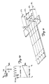
- FIG. 1 is a block diagram of a negative feed back transducer positioning system 8 according to the present invention.
- a stack of magnetically encodable disks is shown generally at 10.
- An electro-mechanical actuator (or E-block) 12 is used to position a servo transducer 14 and a plurality of data transducers 18 radially with respect to a servo disk 16 and data disks 17, respectively.
- the servo transducer is positioned over a desired track on the servo disk 16 where it is held while the data transducers 18, which are also connected to the E-block 12, perform read or write operations.
- the servo transducer 14 reads position information from servo disk 16 and provides position signals to a pre-amplifier 20 where it is amplified and provided to a servo position demodulator 22.
- the servo position demodulator 22 decodes the position information and presents it, in digital form, to a servo control processor 24.
- the servo control processor 24 compares the decoded position signal received from the servo position demodulator 22 with a desired position signal to determine a transducer position error.
- the transducer position error represents the difference between the actual position of the transducer 14, indicated by the decoded position signal, and the desired position indicated by a desired position signal.
- the servo control processor 24 then generates a position correction signal which is converted to an analog signal in digital-to-analog (D/A) converter 26 and applied to the E-block 12 through a power amplifier 28.
- the position correction signal causes the E-block 12 to move the transducers 14, 18 radially with respect to the disks 16, 17 in order to minimise the transducer position error.
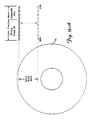
- One disk surface of the servo disk 16 is dedicated to contain servo tracks. This surface is shown in Figure 2.
- the servo position information in the servo tracks is not continuous but is condensed into evenly spaced sectors. This is known as a sectored servo system.
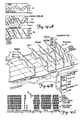
- Figure 3A is an enlarged portion of one servo sector on the servo disk 16.
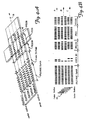
- Figure 3B shows the format of servo information, represented by black and white bars, in one servo sector on the servo disk 16.
- the black and white bars represent oppositely magnetised areas on a surface coating of the servo disk 16.
- the oppositely magnetised areas are recorded close enough together so that the position signal generated by the servo transducer 14 is generally sinusoidal.
- Figure 3B shows that one servo sector contains several distinct fields.
- the fields include a phase locked oscillator/automatic gain control (PLO/AGC) synch field, a track identification (track ID) field, three position error sample (PES) fields and an index field.
- PLO/AGC phase locked oscillator/automatic gain control
- Track ID track identification
- PES position error sample
- Figure 3B also shows the magnetised areas for three tracks A, B and C on servo disk 16 where the outer radius and inner radius of the tracks is indicated.
- the direction of the servo transducer velocity and the track centre of each track is indicated by dashed arrows A, B and C, respectively.
- the sinusoidal position signal represents the magnetically encoded information shown in Figure 3B.
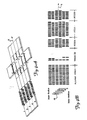
- Figure 4A illustrates the position signal generated by the servo transducer 14 as a function of five radial transducer positions along a single track (for example track B) on the servo disk 16 where position 3 represents the centre of the track.
- Positions 1 and 5 represent off centre positions where the centre of the servo transducer 14 is radially aligned with, and flying over the outer radius or inner radius of track B, respectively. If the servo transducer 14 were tracking along position 1, a position error equal to the radial distance between position 1 and position 3 would exist. Similarly, if transducer 14 were tracking along position 5, a position error equal to the radial distance between position 3 and position 5 would exist.
- Positions 2 and 4 also represent off centre positions. However, the off centre position error is not as large as the error associated with positions 1 and 5.
- Figure 4B shows the spatial relationship between the servo transducer 14, the magnetised areas of the servo disk 16, and each of the transducer positions 1 to 5.
- FIG. 4A shows that, as the servo transducer 14 flies over this region, its output position signal is a constant frequency, independent of the particular track over which it is flying and independent of radial position on the track.
- the information in this field is encoded in this way so that a phase locked oscillator in the servo position demodulator 22 can synchronise with the output of the servo transducer 14.
- the track ID number is encoded as a Gray code where only one bit changes from track to track.
- Each track ID bit is represented by one dibit cell.
- the amplitude of a dibit depends on the radial position of servo transducer 14. If the dibit amplitude exceeds a given threshold, in this embodiment one half the maximum possible amplitude, the dibit is decoded as a logic 1 in the servo position demodulator 22. Otherwise, it is decoded as a logic 0. Therefore, n bit cells define 2 n servo tracks on the disk.
- the magnetic information encoded on adjacent tracks is recorded 180° out of phase. This produces a chequerboard pattern of magnetisation.
- the magnetic information in the PES fields is also recorded plus or minus 90° out of phase with respect to the magnetic information encoded in the PLO/AGC synch field.
- the PES1 field is also called a normal field.
- the boundary between the magnetisation tracks in the normal field are arranged so that they lie on the centre line of the data tracks. Therefore, when the servo transducer 14 is over the normal field, as the servo transducer 14 moves radially further from the centre position 3 of track B, the amplitude of the position signal from the servo transducer 14 is larger. Similarly, as the servo transducer 14 moves radially closer to the centre position 3, the amplitude of the position signal is smaller.
- the PES2 field (also known as a quadrature field) is split in half.
- Half of the quadrature field (the PES2A field) lies on one side of the normal field and half (the PES2B field) lies on an opposite side of the normal field.
- the quadrature field is encoded with a magnetisation pattern which is identical to that of the normal field but which is radially off-set from it by half a track width. Therefore, when the servo transducer 14 is over the quadrature field, the position signal provided by the servo transducer 14 is at a maximum amplitude when the servo transducer 14 is flying over the track centre position 3 and at a minimum amplitude when it is flying over the off centre positions 1 and 5.
- the information read from the normal and quadrature fields is referred to as a position error sample.
- the normal and quadrature fields each produce a separate position error sample.
- the amplitude of the position signal provided by the servo transducer 14 representing the position error samples is a linear function of the distance of the centre of the servo transducer 14 from the track centre (position 3). This is shown theoretically in Figure 5.
- the servo transducer 14 is moving relative to the servo disk 16 in the direction indicated by arrow 30.
- the servo transducer 14 may be regarded as being composed of a set of read elements of differential width operating in parallel, whose output signals are added together or integrated to produce the total output voltage of the position signal from the servo transducer 14.
- the position signal from the servo transducer 14 is sinusoidal. Any fringing field effect is neglected. Since the magnetic pattern in the servo sector was originally written 180° out of phase for adjacent tracks, the signal produced by a differential read element, dy , will be defined as either plus or minus Vm Cos (wt).
- the total output voltage from the servo transducer 14 depends on how many differential read elements produce +Vm Cos (wt) and how many produce -Vm Cos (wt).
- d the distance from the centre of the servo transducer 14 to the nearest data track centre (a boundary between the +Vm Cos (wt) and -Vm Cos (wt) regions in the PES1 field).
- the distance d may be positive (towards the inner radius) or negative (towards the outer radius).
- b the width of the servo transducer 14
- each read element dy contributes a fraction equal to dy/b towards the total output voltage provided by the servo transducer 14.
- the amplitude of the position signal of the servo transducer 14 does not change linearly across the full track width. It becomes non-linear at some point near the outside twenty five percent of the track, depending on the physical dimensions of the servo transducer 14 and its relationship to the dimensions of the written magnetised pattern.
- FIG. 4A shows the quadrature relationship between the PES2A and the PES2B fields and the PES1 field.
- the amplitude of the position signal provided by the servo transducer 14 in the PES2 field is at a maximum, and therefore in a non-linear region when the amplitude in the PES1 field is at a minimum (and therefore in a linear regions, and vice versa.
- either the quadrature or the normal field is always in a linear region and there is always a linear relationship between the position signal corresponding to one of the PES fields (PES1 or PES2) and the distance between the centre of the servo transducer 14 and the track centre (the off track error) no matter where the servo transducer 14 is positioned across the radial width of a track on the servo disk 16.
- PES1 or PES2 the position signal corresponding to one of the PES fields
- FIG. 6 is a more detailed block diagram of the servo position demodulator 22 which decodes position information represented by the analog position signal from the servo transducer 14.
- the position signal from the servo transducer 14 is applied to a filter 32 where it is filtered to remove high frequency noise.
- the filtered signal is then applied to an automatic gain control (AGC) loop 34 ( Figure 6B).
- AGC automatic gain control
- the AGC loop 34 is comprised of a voltage controlled amplifier 36, an analog multiplier 38, a voltage-to-current converter 40 and a current summing junction 42.
- An analog switch 44 and a capacitor 46 allow the AGC loop 34 to be configured in an acquire mode or a hold mode (explained later).
- An overall reference for the automatic gain controlled amplitude is provided through a filter 48 by a micro-processor (not shown).
- the overall reference determines the final position gain in volts per microinch.
- the AGC loop 34 is initially calibrated by the micro-processor and compensates for changes in input signal. amplitude due to changes in track radius, flying height and other media properties.
- an automatic gain. controlled (AGC'd) analog signal from the AGC loop 34 is transmitted to a voltage comparator 50 which generates serial digital data corresponding to the AGC'd analog signal.
- the comparator 50 provides the serial digital data to a synch detector circuit 52 and a serial-to-parallel shift register 54.
- the synch detector circuit 52 identifies the start of a servo sector and enables a programmable event generator (PEG) 56.
- the programmable event generator 56 produces timing and window logic signals required for position demodulation in the servo position demodulator 22.
- the comparator 50 decodes track ID dibits as either logic 1 or logic 0 depending on their amplitude.
- the comparator 50 has a threshold of one half the maximum automatic gain controlled amplitude.
- the serial digital track ID bits are shifted into the shift register 54 to produce a parallel track ID word.
- This track ID word is in Gray code and is converted to a binary track ID word by combinational logic 58.
- the binary track ID word is latched in a latch 60 and provided to track ID correction logic 62 which will be explained in more detail later.
- the output of the correction logic 62 is a track identification signal or absolute position signal which identifies the particular track over which the servo transducer 14 is flying.
- the shift register 54 is also used to provide index information to an index pattern detector 64 which is not important to an understanding of the present invention and so will not be discussed further.
- the AGC'd analog signal from the AGC loop 34 is also transmitted to a phase locked oscillator loop (PLO loop) 66 ( Figure 6A).
- the PLO loop 66 comprises an analog switch 68, a phase comparator/multiplier 70, a voltage-to-current conververter (charge pump) 72, which includes a balance circuit 74 for balancing the voltage-to-current converter 72 once per servo sector so that there is zero current output for zero voltage input, an analog switch 76, a filter 78, a voltage controlled oscillator 80 and a clock generator 82.
- the PLO loop 66 locks onto the phase and frequency of the AGC'd analog signal provided by the AGC loop 34.
- the analog switch 76 is opened allowing the PLO loop 66 to open.
- the signal provided to the voltage controlled oscillator 80 is then held constant. Hence, a constant frequency results at the output of the voltage controlled oscillator 80. Therefore, the frequency of a digital feed back signal 120 from the clock generator 82 is also constant.
- the output of voltage to the voltage-to-current converter 72 is also provided to a PES capacitor 84 through an analog switch 86. Voltage is integrated on the capacitor 84 during synchronous demodulation of PES fields PES1, PES2A and PES2B. This voltage is applied through a buffer 88 to an analog-to-digital (A/D) converter 90.
- the output of the A/D converter 90 is provided to a composite PES generator logic 92.
- the composite PES generator logic 92 comprises latches 94, 96, a digital adder 98, multiplexers 100 and 102, multiplexer control logic 104, a switchable inverter 106 and inverter control logic 108.
- the output of the composite PES generator logic 92 is a composite PES word or fine position off track error which represents the distance that the servo transducer 14 is tracking from the track centre.
- the digital position word defines the radial position of the servo transducer 14 on the servo disk 16 in a continuous fashion down to approximately one or two micro-inches of quantisation.
- the PES capacitor 84 is also selectively connected to a DC null loop 110 comprised of the A/D converter 90, a one-bit latch 112, and integrator 114, a buffer 116, an analog switch 118 and the buffer 88.
- the DC null loop 110 drives the initial voltage on the PES capacitor 84 to a mid-point between upper and lower reference voltages applied to an internal resistor ladder in the A/D converter 90.
- Figure 7 is a timing diagram which shows the relationship between logic control signals generated by the programmable event generator 56, the analog position signal and the PES capacitor voltage as the servo transducer 14 moves over one servo sector.
- Figure 8 is a timing diagram showing the relationship between various signals related to the synchronous demodulation of the fine position information in the servo position demodulator 22 as the servo transducer 14 moves along one servo sector.
- the programmable event generator 56 closes the switch 44 to close the AGC loop 34.
- the AGC loop 34 acquires the proper gain so that the amplitude of the analog position signal is compensated for amplitude changes caused by changes in track radius, transducer flying height, and other media properties.
- the programmable event generator 56 closes the analog switches 68, 76 to close the PLO loop 66.
- the voltage control oscillator 80 locks onto the phase and frequency of the AGCd analog signal provided by the AGC loop 34.
- the PLO loop 66 uses the digital feed back signal 120 which locks in at a 90° phase shift from the AGC'd analog signal provided by the AGC loop 34.
- the analog switches 44, 76 are opened and both the AGC loop 34 and the PLO loop 66 enter a hold mode. While in the hold mode the amplification in the AGC loop 34 and the phase and frequency of the feed back signal 120 in the PLO loop 66 remain constant.
- the servo transducer 14 passes over the track ID field in the servo sector.
- the serial digital track ID bits are formed by the comparator 50 and shifted into the shift register 54.
- the Gray code track bits are converted into a binary code by the converter 58 and latched into the latch 60.
- the servo transducer 14 enters the PES fields in the servo sector.
- the switch 68 is closed applying the analog position signal to the phase comparator/multiplier 70 while the switch 76 remains open.
- the feed back signal 120 is multiplied by the analog position signal in the phase comparator/multiplier 70. Since the information in the PLO/AGC synch field is recorded 90° out of phase with the information in the PES fields, and since the feed back signal 120 is held with a 90° phase shift, the multiplication performed at the phase comparator/multiplier 70 produces a full wave rectification of the analog position signal. This is shown by plot C in Figure 8.
- Figure 9A illustrates the output of the phase comparator/multiplier 70 for the five radial positions of the servo transducer 14 which were described earlier with reference to Figure 4A.
- Figure 9B shows the spatial relationship between the centre of the servo transducer 14 and the centre of track B in radial transducer positions 1 to 5.
- the amplitude of output signal of the phase comparator/multiplier 70 is proportional to the distance between the centre of the servo transducer 14 and the centre of track B.
- the polarity of the DC component of the signal indicates the direction of the off-set.
- Figure 10 illustrates the general case where n cycles of current are integrated to produce the analog voltage on the PES capacitor 84 corresponding to one PES field.
- the final voltage on the PES capacitor 84 is also proportional to the number, n , of cycles integrated.
- n cycles are integrated and the A/D converter 90 converts the analog voltage on the PES capacitor 84 into a digital signal which is latched in the latch 94.
- first n/2 cycles for the PES2A field
- the A/D converter 90 converts the value to a digital signal which is latched in the latch 96.
- another n/2 cycles for the PES2B field
- another A/D conversion is made by the A/D converter 90.
- the resulting digital signal is provided to the adder 98 where the digital signal representing the PES2A field is added to it to produce a full PES2 position sample.
- the number of cycles, n chosen should be high enough to achieve the averaging of possible media defects over several cycles. However, it must not be so high as to produce an overly long servo sector since the length of the servo sector limits the maximum radial velocity of the servo transducer 14.
- the final voltage on the PES capacitor 84 is also proportional to the capacitance of the PES capacitor 84. Note that the same PES capacitor 84 is used to produce the analog PES voltage for both the PES1 and PES2 position samples. After the A/D conversion of the final ramp voltage of a PES measurement, the digital result is latched so the analog voltage on the PES capacitor 84 can be re-set, and the same PES capacitor 84 can be reused for the next PES measurement. This eliminates the possibility of position error due to capacitance mismatch which would result if two or more capacitors were used to produce the analog PES voltage. Using only one capacitor to integrate the position signal for both the quadrature and normal fields increases the accuracy with which the servo transducer 14 follows the track.
- A/D converter 90 is required to convert the analog PES voltages to digital signals. This lowers the overall cost of the servo position demodulator 22. Also, the A/D conversion made by the A/D converter 90 is made early in the processing chain in the servo position demodulator 22. The addition of the PES2A and PES2B position samples and the formation of the composite PES signal all take place in the digital domain. This minimises the amount of analog circuitry and associated errors such as off-set errors, gain errors, linearity errors and variation with temperature. Additionally, all of the digital circuits can be fabricated into one compact integrated circuit to save space.
- FIG. 12A shows the DC null loop 110 in greater detail and Figure 12B is a timing diagram showing the relationship between signals occurring in the DC null loop 110.
- programmable event generator 56 generates a signal on an output L7 causing the A/D converter 90 to perform a first A/D conversion.
- the A/D converter 90 comprises a resistor ladder connected between reference voltages VREF+ and VREF-, 15 comparators including a most significant bit comparator 130, and a logic decode 132 which decodes a most significant bit of the A/D converter 90.
- Resistors R1 and R2 which represent the resistor ladder condensed into two resistors, act as a voltage divider creating an internal voltage mid-point Vmidref at a node 129.
- the most significant bit of the A/D converter 90 is decoded and latched into the one-bit latch 112.
- the value of the latched most significant bit depends on whether signal Vin is greater or less than the internal voltage Vmidref at the node 129.
- the gain in the AGC loop 34 is set so that the A/D converter 90 full digital scale corresponds to one half of a servo track.
- the internal voltage Vmidref corresponds to the track centre or zero position error.
- the latched, most significant bit is applied to the integrator 114.
- the output of the integrator 114 an external voltage Vmidref at a node 134, is driven towards the value of the internal voltage Vmidref.
- the gain through the integrator 114 is chosen so that the external voltage Vmidref just crosses the internal voltage Vmidref before the next servo sector. This is shown in Figure 12B.
- the peak to peak limits of the external voltage Vmidref must be kept much lower than the analog value of a least significant bit of the A/D converter 90. This keeps the initial voltage on the PES capacitor 84 as close as possible to the exact centre of the digital scale
- the switch 118 is opened and the A/D converter 90 is available for conversions 2, 3 and 4 which are conversions for the position samples read from the PES2A, PES1 and PES2B fields. Between position samples, the switch 118 closes to re-set the PES capacitor 84 to the external voltage Vmidref. Hence, the DC null loop 110 compensates for static or time variable DC off-sets in the buffer 88 and the switch 118, which are inside the DC null loop 110. This increases the track following accuracy of the servo transducer 14.
- the output of voltage to the voltage-to-current converter 72 is connected to the PES capacitor 84 through the analog switch 86 and the PES capacitor voltage ramps up or down as shown in Figure 8.
- the difference between the final voltage on the PES capacitor 84 and the initial voltage is proportional to the distance of the centre of the servo transducer 14 from the track centre.
- Figure 13A shows the concept of a total position word.
- the track ID number and the digital value representing the PES field samples are combined to define the radial position of the servo transducer 14 anywhere on the servo disk 16.
- the track ID number defines the track and the PES samples define the position within the track.
- the servo transducer 14 flies over the track on the servo disk 16, it moves over the track ID field prior to moving over the PES fields. Hence, the track ID information is decoded earlier in time than information read from the PES fields. Since the information read from the PES fields is read later in time, it is more recent and, hence, more accurate position information than that read from the track ID field.
- the servo transducer 14 is moving radially, it has a slanted trajectory across the servo sector. Therefore, it may enter the servo sector in the track ID field of one track but cross a boundary between tracks and exit the servo sector from the PES field of the next track.
- correction logic 140 (shown in Figures 6B and 13D) is used to detect when it is necessary to correct the track ID so that it corresponds to the track number from which the PES field samples were read.
- Figure 13B is a graph of the amplitude of the position signal corresponding to the PES fields, in 2's complement form, as it relates to the least significant bit in the track ID signal.
- Figure 13B also shows a corrected least significant bit in the track ID signal.
- Trace A represents the 2's complement form of the amplitude of the position signal corresponding to the PES1 field.
- Trace B represents the 2's complement amplitude corresponding to the PES2 field (the PES2A field + the PES2B field).
- the truth table shown in Figure 13C defines the conditions where the track ID information is not correlated with the PES field information and the correction word which is required.
- the correction logic 140 forms a correction number of ⁇ 1 which is added to the track ID in an adder 142. For all other cases, the number 0 is added to the track ID.
- Figure 13E shows the correction logic 140 in more detail. It should be noted that the addition of the correction word to the track ID could also be accomplished by software in the servo control processor 24.
- This correlation allows the servo control processor 24 to use bits of the digital composite PES signal along with a track ID to determine very precisely the position and velocity of the servo transducer 14 even at high radial velocities.
- the increased accuracy of the total position signal at high radial velocities helps to minimise both the time and power required for performing a track seek operation.
- this correlation permits a smoother settling of the servo transducer on a track.
- Figure 14A is an imaginary tracing of digitised final voltage values of the analog PES ramps generated at the PES capacitor 84 for all radial positions of the servo transducer 14 across four adjacent tracks in a servo-on-data system. These imaginary tracings are called track crossing plots. The digital values are in 2's complement form and the point at which the track crossing plot for the PES1 field crosses 00 hex represents the track centre.
- Graph G1 in Figure 14A shows the three track crossing plots condensed onto a single plane. Since there are equal number of cycles in the PES2A field and the PES2B field, their corresponding track crossing plots coincide. However, since the integration measurement time period for the PES2A and PES2B fields is only one half that of the PES1 field, the slope of the PES2A and PES2B track crossing plots in volts per micro-inch is only one half that of the PES1 track crossing plot.
- the PES2A position sample is added to the PES2B position sample to produce the total PES2 or quadrature sample.
- One hardware implementation to perform this addition was discussed with reference to Figure 6. This addition can also be performed graphically.
- Graph G2 in Figure 14A shows that the addition of the PES2A and PES2B track crossing plots produces a new track crossing plot which has the same slope as the PES1 track crossing plot.
- the PES1 and PES2 track crossing plots shown in graph G2 in Figure 14A are the inputs to the composite PES generator 92. However, at only one radial position along the servo disk 16, only one of the two plots is in a region where the PES amplitude is changing linearly with transducer position. There are eight distinct regions labelled a to h which repeat across the track.
- the composite PES generator 92 determines over which of the eight regions the servo transducer 14 is flying. The composite PES generator 92 then creates a composite position error sample output which is the standardised form of position error sample required by the servo control processor 24.
- the composite PES generator 92 accomplishes this by inverting the slope or changing the sign bit of the PES1 or PES2 track crossing plots when necessary, and combining the linear portions to create the desired composite PES track crossing plot shown in graph G3 in Figure 14A.
- Figures 15A to 15C show how the addition of the PES2A and PES2B position samples helps to compensate for high radial velocity of the servo transducer 14.
- a slanted trajectory of the servo transducer 14 is shown by arrow 150 in Figure 15A. This slanted trajectory causes an apparent shift in the PES1 and PES2B track crossing plots as shown in Figure 15B.
- the actual value of the PES2A and PES2B fields is shown by a solid line and the ideal value is shown by a dashed line.
- a new track crossing plot, PES2C is formed as shown in Figure 15C.
- the PES2C track crossing plot has the correct orientation with respect to the PES1 track crossing plot.
- This invention is not limited for use in dedicated servo systems such as the one shown in Figure 1.
- This invention may also be used in hydrid servo configurations.
- a hybrid system has a dedicated surface containing servo sectors and other disks which contain one or more similar servo sectors per revolution which are decoded for data transducer thermal off-set compensation. Since a common servo sector pattern is used, through the use of time multiplexing only one servo position demodulator is needed.
- the present invention may also be used in servo-on-data type servo systems where each disk surface has servo sectors.
- customer data is written between the write protected servo sectors. Any head actively reading or writing customer data is also acting as its own track following error sensor. This increases track following precision and allows higher track densities to be achieved.
- FIG. 17 Another servo system configuration in which this invention may be used is one having multiple independent actuators 200. This is shown in Figure 17. If a multiple actuator system contains n actuators 200 and corresponding amplifiers 202, the servo sectors under servo transducers 204 on adjacent actuators are staggered by 1/n of the distance between servo sectors on one disk. The servo sectors for adjacent actuators must not overlap. This is illustrated in Figure 18. In this type of system, a multiplexer 205 continuously cycles through the servo sectors of the actuators 200. The advantage of this configuration is that only one servo control processor 24, along with a digital. demultiplexer 206, D/A converters 208, the amplifiers 202 and one servo demodulator 22 are needed to control several actuators 200 (again through the use of time multiplexing).
- the servo sector format described in this invention may be used with linear or rotary actuators.
- FIG. 16A to 16C A method for creating the composite PES output for a dedicated servo system is shown in Figures 16A to 16C.
- the servo track width can be twice the data track width.
- the servo transducer 14 is then twice as wide as a data transducer 18. This can help minimise non-linear effects of fringing fields read by the edges of the servo transducer 14. It can also improve the signal to noise ratio of the track ID bits.
- the composite PES generator 92 merely inverts the slope of the d , e , f and g segments.
- the servo track centres are derived alternately from PES1 and PES2 position samples.
- the transducer is used for both serving and reading and writing customer data.
- the servo track and data track are automatically the same width.
- the composite PES track crossing plot is then formed as shown in graph G3 in Figure 14A. Slope segments a and d are re-positioned to extend the linearity of the b and c segments. This produces a linear PES plot across the full track width. Similarly, the e and h segments extend the linearity of the f and g segments.
- the track centre is always derived from the PES1 position sample.
- One advantageous feature of this method is that the composite PES field has one more bit of quantisation than the A/D converter 90 used in the servo position demodulator 22.
- the present invention uses only one integrating capacitor for integrating position error signals in both the quadrature and normal fields in the servo position demodulator 22. This eliminates any position error caused by differences in capacitance in theoretically matched capacitors used in prior systems.
- the A/D converter 90 is time multiplexed into the DC null loop as well as the PES conversions. This reduces the cost of the servo position demodulator 22.
- the nulling system compensates for static or time variable DC off-sets in the electronics surrounding the integrating capacitor This increases the track following accuracy of the positioning system 8.
Abstract
Description
- This invention relates to demodulation of position information signals provided by a transducer in response to position information read from the disk.
- Disk file data storage systems contain one or more magnetic disks on which data is stored in concentric tracks. A transducer writes, or magnetically encodes, the data on the track. The transducer is also capable of reading the magnetically encoded data from the tracks.
- An electro-mechanical actuator operates within a negative feed back, closed loop servo system. The actuator moves the transducer radially for track seek operations and holds the transducer directly over a track for track following operations.
- A servo transducer reads position information from the disk and provides a position signal which is decoded by a position demodulator and presented in digital form to a servo control micro-processor. The servo control micro-processor essentially compares actual radial position of the transducer over the disk with desired position and commands the actuator to move in order to minimise position error.
- In one type of servo system, one disk surface is dedicated to contain servo tracks which are encoded with servo position information. The servo position information in the servo tracks is condensed to evenly spaced sectors. A servo transducer flies over the servo sectors as the disk rotates and produces a sampling effect. The actual position transducer information is up-dated at the end of each servo sector through the use of track identification information and position error information. The track identification number is prewritten into each servo sector and serves as coarse transducer position information. The position error information is written in the servo sector and represents the distance that the servo transducer is located from the centre of the track. This position error information serves as fine transducer position information.
- The position error information is generally written in two fields. One is referred to as a quadrature field and the second is called a normal field. Position error information obtained from the normal field or the quadrature field is called a normal or quadrature position sample. By decoding the position samples obtained from these two fields, the off track position of the transducer is determined relative to the centre of the track. The position samples are typically decoded by integrating the analog position signal provided by the transducer which represents the position error information magnetically encoded on the disk. The integrated signal is then converted to a digital signal representing transducer position error.
- In the past, two separate, theoretically identical, capacitors were used for integrating signals representing the normal and quadrature position samples. However, although the capacitors were theoretically identical, some difference between the capacitance values often existed. This difference produced an error factor between the normal and quadrature samples. Further, since two capacitors were used for integration in some cases, two analog-to-digital (A/D) converters were required to convert the final analog voltage across each of the capacitors. Using two A/D convertors not only increased the cost of the demodulator, but introduced additional errors due to various off-sets in the A/D converters.
- Additionally, in the past, the position samples decoded from the quadrature and normal fields were combined in the analog domain to produce a composite position error signal. This technique increased inaccuracies in the demodulator. These inaccuracies were due to the analog circuits which each had associated off-set errors, gain errors, linearity errors and variation with temperature and which were used for combining the position samples.
- Further, before integrating the transducer position signal, and between integrations, it is desirable to keep the initial voltage on the integrating capacitors as close to a zero error level as possible.
- For these reasons, there is a need for a more accurate servo position demodulator with a null system which compensates for static or time variable DC offsets in the electronics surrounding the capacitor.
- According to one aspect of the present invention, there is provided a demodulating system for demodulating position information signals provided by a transducer in response to position information read from a disk in a data storage system, characterised by comprising: amplifier means, coupled to the transducer, for amplifying the position information signals to provide amplified position signals; rectifier means, coupled to the amplifier means, for rectifying the amplified position signals to provide rectified position signals; first integrating means, selectively coupled to the rectifier means, for integrating the rectified position signals to produce position error signals; an analog-to-digital converter coupled to the first integrating means, for converting the position error signals into logic output signals representative of the position error signals; and nulling means, selec- tively coupled to the first integrating means, for providing the first integrating means with a reference signal to initialise the first integrating means, the A/D converter of the converter means being time multiplexed.
- According to a further aspect of the present invention, there is provided a method of demodulating analog position information signals provided by a transducerin response to position information read from a quadrature field and a normal field on a disk in a data storage system, the method being characterised by comprising: rectifying the analog position information signals to provide rectified position signals; integrating the rectified position signals to produce position error signals; converting the position error signals to digital logic signals representative of the position information read from both the quadrature field and the normal field; and combining the digital logic signals to form a composite position error signal representative of the position information read from both the quadrature field and the normal field where the step of combining is performed after the step of converting.
- According to yet another aspect of the present invention, there is provided a demodulating system for demodulating position information signals provided by a transducer in response to position information read from a quadrature field and a normal field on a disk in a disk storage system, characterised by comprising: rectifier means, coupled to the transducer, for rectifying the position information signals to provide rectified position signals; integrating means, coupled to the rectifier means, for integrating the rectified position signals to produce position error signals; converter means, coupled to the integrating means, for converting the position error signals to digital logic signals representative of the position information read from both the quadrature field and the normal field; and composite generator means, coupled to the converter means, for combining the digital logic signals to form a composite position error signal representative of the position information read from both the quadrature field and the normal field where the composite generator means combines the digital logic signals after they have been converted by the converter means.
- The invention is illustrated, merely by way of example, in the accompanying drawings, in which:-
- Figure 1 is a block diagram of one embodiment of a demodulating system according to the present invention;
- Figure 2 is a view of a disk surface used in a sectored servo system;
- Figure 3A is an enlarged view of a portion of a servo sector of the disk shown in Figure 2;
- Figure 3B is a diagram of the format of servo information in one servo sector of Figure 3A;
- Figure 4A shows a transducer output signal amplitude as a function of track radius for one servo sector;
- Figure 4B shows the relationship between the transducer and magnetised areas on the disk;
- Figure 5 is a diagram used to describe mathematically the amplitude of the transducer output signal as a linear function of the distance of the transducer centre from the track centre;
- Figure 6 is a detailed block diagram of a servo position demodulator;
- Figure 7 is a timing diagram showing PES capacitor voltage during one servo sector;
- Figure 8 is a timing diagram showing the relationship between events in the servo position demodulator of Figure 6;
- Figure 9A is a graph showing the output of a multiplier of the servo position demodulator of Figure 6 as a function of track radius;
- Figure 9B is a diagram showing magnetised bits in a servo sector and the position of the transducer which corresponds to the positions in Figure 9A;
- Figure 10 is a diagram which illustrates the relationship between the final voltage on the PES capacitor and the off track error of the transducer;
- Figure 11 is a graph of an analog voltage PES1 versus track radius of the transducer in one servo sector;
- Figure 12A is a more detailed block diagram of a DC null loop;
- Figure 12B is a timing diagram showing the relationship between key signals in the DC null loop of Figure 12A;
- Figure 13A shows the concept of a total position word;
- Figure 13B is a diagram showing PES voltages and the least significant bit of the raw track identification number as a function of transducer position;
- Figure 13C is a truth table giving the correction number for each case shown in Figure 13A;
- Figure 13D is a block diagram of a track identification correction feature;
- Figure 13E shows one implementation of the track identification correction feature;
- Figure 14A shows track crossing plots for the PES fields in a servo on-data-system;
- Figure 14B shows the relationship between the transducer position in the servo sector and the track crossing plots;
- Figure 14C shows the position of the transducer over one track in the servo sector;
- Figure 15A shows transducer trajectory over a servo sector caused by radial movement of the transducer as the disk rotates;
- Figure 15B is a plot showing the effect of radial velocity of the transducer on the PES track crossing plots;
- Figure 15C shows the corrected PES track crossing plots after being compensated for radial velocity of the transducer;
- Figure 16A shows the track crossing plots for the PES fields in a dedicated servo system;
- Figure 16B shows the relationship between the transducer position in the servo sector and the track crossing plots;
- Figure 16C shows the position of the transducer over one track in the servo sector;
- Figure 17 shows a servo system having multiple independent actuators; and
- Figure 18 shows a top view of a disk in the servo system shown in Figure 17.
- Figure 1 is a block diagram of a negative feed back
transducer positioning system 8 according to the present invention. A stack of magnetically encodable disks is shown generally at 10. An electro-mechanical actuator (or E-block) 12 is used to position aservo transducer 14 and a plurality ofdata transducers 18 radially with respect to aservo disk 16 anddata disks 17, respectively. The servo transducer is positioned over a desired track on theservo disk 16 where it is held while thedata transducers 18, which are also connected to the E-block 12, perform read or write operations. - The
servo transducer 14 reads position information fromservo disk 16 and provides position signals to apre-amplifier 20 where it is amplified and provided to aservo position demodulator 22. Theservo position demodulator 22 decodes the position information and presents it, in digital form, to aservo control processor 24. Theservo control processor 24 compares the decoded position signal received from theservo position demodulator 22 with a desired position signal to determine a transducer position error. The transducer position error represents the difference between the actual position of thetransducer 14, indicated by the decoded position signal, and the desired position indicated by a desired position signal. - The
servo control processor 24 then generates a position correction signal which is converted to an analog signal in digital-to-analog (D/A) converter 26 and applied to the E-block 12 through apower amplifier 28. The position correction signal causes the E-block 12 to move thetransducers disks - One disk surface of the
servo disk 16 is dedicated to contain servo tracks. This surface is shown in Figure 2. The servo position information in the servo tracks is not continuous but is condensed into evenly spaced sectors. This is known as a sectored servo system. Theservo transducer 14, flying over the servo sectors as theservo disk 16 rotates, produces a sampling effect in which the actual, decoded position information provided to theservo control processor 24 is up-dated at the end of each servo sector. - Figure 3A is an enlarged portion of one servo sector on the
servo disk 16. Figure 3B shows the format of servo information, represented by black and white bars, in one servo sector on theservo disk 16. The black and white bars represent oppositely magnetised areas on a surface coating of theservo disk 16. The oppositely magnetised areas are recorded close enough together so that the position signal generated by theservo transducer 14 is generally sinusoidal. - Figure 3B shows that one servo sector contains several distinct fields. The fields include a phase locked oscillator/automatic gain control (PLO/AGC) synch field, a track identification (track ID) field, three position error sample (PES) fields and an index field. Figure 3B also shows the magnetised areas for three tracks A, B and C on
servo disk 16 where the outer radius and inner radius of the tracks is indicated. The direction of the servo transducer velocity and the track centre of each track is indicated by dashed arrows A, B and C, respectively. - As the
servo transducer 14 flies over the tracks A, B or C on theservo disk 16, it generates a generally sinusoidal position signal. The sinusoidal position signal represents the magnetically encoded information shown in Figure 3B. - Figure 4A illustrates the position signal generated by the
servo transducer 14 as a function of five radial transducer positions along a single track (for example track B) on theservo disk 16 whereposition 3 represents the centre of the track.Positions servo transducer 14 is radially aligned with, and flying over the outer radius or inner radius of track B, respectively. If theservo transducer 14 were tracking alongposition 1, a position error equal to the radial distance betweenposition 1 andposition 3 would exist. Similarly, iftransducer 14 were tracking alongposition 5, a position error equal to the radial distance betweenposition 3 andposition 5 would exist. -
Positions positions servo transducer 14, the magnetised areas of theservo disk 16, and each of thetransducer positions 1 to 5. - The information encoded in the PLO/AGC synch field is identical in phase and frequency from track to track along the
servo disk 16. Therefore, Figure 4A shows that, as theservo transducer 14 flies over this region, its output position signal is a constant frequency, independent of the particular track over which it is flying and independent of radial position on the track. The information in this field is encoded in this way so that a phase locked oscillator in theservo position demodulator 22 can synchronise with the output of theservo transducer 14. - In the track ID field, the track ID number is encoded as a Gray code where only one bit changes from track to track. Each track ID bit is represented by one dibit cell. The amplitude of a dibit depends on the radial position of
servo transducer 14. If the dibit amplitude exceeds a given threshold, in this embodiment one half the maximum possible amplitude, the dibit is decoded as alogic 1 in theservo position demodulator 22. Otherwise, it is decoded as alogic 0. Therefore, n bit cells define 2n servo tracks on the disk. - In the PES fields (PES1, PES2A and PES2B) the magnetic information encoded on adjacent tracks is recorded 180° out of phase. This produces a chequerboard pattern of magnetisation. The magnetic information in the PES fields is also recorded plus or minus 90° out of phase with respect to the magnetic information encoded in the PLO/AGC synch field.
- The PES1 field is also called a normal field. The boundary between the magnetisation tracks in the normal field are arranged so that they lie on the centre line of the data tracks. Therefore, when the
servo transducer 14 is over the normal field, as theservo transducer 14 moves radially further from thecentre position 3 of track B, the amplitude of the position signal from theservo transducer 14 is larger. Similarly, as theservo transducer 14 moves radially closer to thecentre position 3, the amplitude of the position signal is smaller. - The PES2 field (also known as a quadrature field) is split in half. Half of the quadrature field (the PES2A field) lies on one side of the normal field and half (the PES2B field) lies on an opposite side of the normal field. The quadrature field is encoded with a magnetisation pattern which is identical to that of the normal field but which is radially off-set from it by half a track width. Therefore, when the
servo transducer 14 is over the quadrature field, the position signal provided by theservo transducer 14 is at a maximum amplitude when theservo transducer 14 is flying over thetrack centre position 3 and at a minimum amplitude when it is flying over theoff centre positions - The information read from the normal and quadrature fields is referred to as a position error sample. The normal and quadrature fields each produce a separate position error sample. The amplitude of the position signal provided by the
servo transducer 14 representing the position error samples is a linear function of the distance of the centre of theservo transducer 14 from the track centre (position 3). This is shown theoretically in Figure 5. - The
servo transducer 14 is moving relative to theservo disk 16 in the direction indicated byarrow 30. Theservo transducer 14 may be regarded as being composed of a set of read elements of differential width operating in parallel, whose output signals are added together or integrated to produce the total output voltage of the position signal from theservo transducer 14. For a first order approximation, it is assumed that the position signal from theservo transducer 14 is sinusoidal. Any fringing field effect is neglected. Since the magnetic pattern in the servo sector was originally written 180° out of phase for adjacent tracks, the signal produced by a differential read element, dy, will be defined as either plus or minus Vm Cos (wt). The total output voltage from theservo transducer 14 depends on how many differential read elements produce +Vm Cos (wt) and how many produce -Vm Cos (wt). - To express this mathematically, let d equal the distance from the centre of the
servo transducer 14 to the nearest data track centre (a boundary between the +Vm Cos (wt) and -Vm Cos (wt) regions in the PES1 field). The distance d may be positive (towards the inner radius) or negative (towards the outer radius). If b equals the width of theservo transducer 14, then each read element dy contributes a fraction equal to dy/b towards the total output voltage provided by theservo transducer 14. The integral for the PES1 field as shown in Figure 5 is solved as follows:
b core gap width oftransducer 14
Vm = maximum amplitude
d = off track error
w = frequency of position signal. - The results show that the position signal of the servo transducer 14 V(t) has an amplitude which is a linear function of the off track error, d. This effect can be seen visually in Figure 4A where the signal amplitude in the PES1 field is proportional to the distance of the centre of the
servo transducer 14 from the track centre,radial position 3. Also the polarity of the position signal generated by theservo transducer 14 which corresponds to the PES1 field indicates the direction of the off track error, d. - In reality, the amplitude of the position signal of the
servo transducer 14 does not change linearly across the full track width. It becomes non-linear at some point near the outside twenty five percent of the track, depending on the physical dimensions of theservo transducer 14 and its relationship to the dimensions of the written magnetised pattern. - However, the presence of the quadrature field (PES2) allows the servo position demodulator 22 to overcome this non-linearity. Figure 4A shows the quadrature relationship between the PES2A and the PES2B fields and the PES1 field. The amplitude of the position signal provided by the
servo transducer 14 in the PES2 field is at a maximum, and therefore in a non-linear region when the amplitude in the PES1 field is at a minimum (and therefore in a linear regions, and vice versa. Hence, either the quadrature or the normal field is always in a linear region and there is always a linear relationship between the position signal corresponding to one of the PES fields (PES1 or PES2) and the distance between the centre of theservo transducer 14 and the track centre (the off track error) no matter where theservo transducer 14 is positioned across the radial width of a track on theservo disk 16. - Figure 6 is a more detailed block diagram of the
servo position demodulator 22 which decodes position information represented by the analog position signal from theservo transducer 14. The position signal from theservo transducer 14 is applied to afilter 32 where it is filtered to remove high frequency noise. The filtered signal is then applied to an automatic gain control (AGC) loop 34 (Figure 6B). - The
AGC loop 34 is comprised of a voltage controlled amplifier 36, an analog multiplier 38, a voltage-to-current converter 40 and a current summingjunction 42. Ananalog switch 44 and acapacitor 46 allow theAGC loop 34 to be configured in an acquire mode or a hold mode (explained later). - An overall reference for the automatic gain controlled amplitude is provided through a
filter 48 by a micro-processor (not shown). The overall reference determines the final position gain in volts per microinch. - The
AGC loop 34 is initially calibrated by the micro-processor and compensates for changes in input signal. amplitude due to changes in track radius, flying height and other media properties. - Once properly amplified, an automatic gain. controlled (AGC'd) analog signal from the
AGC loop 34 is transmitted to avoltage comparator 50 which generates serial digital data corresponding to the AGC'd analog signal. Thecomparator 50 provides the serial digital data to asynch detector circuit 52 and a serial-to-parallel shift register 54. - The
synch detector circuit 52 identifies the start of a servo sector and enables a programmable event generator (PEG) 56. Theprogrammable event generator 56 produces timing and window logic signals required for position demodulation in theservo position demodulator 22. - Next, the
comparator 50 decodes track ID dibits as eitherlogic 1 orlogic 0 depending on their amplitude. In this embodiment, thecomparator 50 has a threshold of one half the maximum automatic gain controlled amplitude. The serial digital track ID bits are shifted into theshift register 54 to produce a parallel track ID word. This track ID word is in Gray code and is converted to a binary track ID word by combinational logic 58. The binary track ID word is latched in alatch 60 and provided to trackID correction logic 62 which will be explained in more detail later. The output of thecorrection logic 62 is a track identification signal or absolute position signal which identifies the particular track over which theservo transducer 14 is flying. - The
shift register 54 is also used to provide index information to anindex pattern detector 64 which is not important to an understanding of the present invention and so will not be discussed further. - The AGC'd analog signal from the
AGC loop 34 is also transmitted to a phase locked oscillator loop (PLO loop) 66 (Figure 6A). ThePLO loop 66 comprises ananalog switch 68, a phase comparator/multiplier 70, a voltage-to-current conververter (charge pump) 72, which includes abalance circuit 74 for balancing the voltage-to-current converter 72 once per servo sector so that there is zero current output for zero voltage input, ananalog switch 76, afilter 78, a voltage controlledoscillator 80 and a clock generator 82. ThePLO loop 66 locks onto the phase and frequency of the AGC'd analog signal provided by theAGC loop 34. Then, theanalog switch 76 is opened allowing thePLO loop 66 to open. The signal provided to the voltage controlledoscillator 80 is then held constant. Hence, a constant frequency results at the output of the voltage controlledoscillator 80. Therefore, the frequency of a digital feed back signal 120 from the clock generator 82 is also constant. - The output of voltage to the voltage-to-
current converter 72 is also provided to aPES capacitor 84 through ananalog switch 86. Voltage is integrated on thecapacitor 84 during synchronous demodulation of PES fields PES1, PES2A and PES2B. This voltage is applied through abuffer 88 to an analog-to-digital (A/D)converter 90. The output of the A/D converter 90 is provided to a compositePES generator logic 92. The compositePES generator logic 92 compriseslatches 94, 96, adigital adder 98,multiplexers multiplexer control logic 104, aswitchable inverter 106 andinverter control logic 108. The output of the compositePES generator logic 92 is a composite PES word or fine position off track error which represents the distance that theservo transducer 14 is tracking from the track centre. - The composite PES word, together with the corrected track ID word, form one digital position word which is typically 19 bits long. The digital position word defines the radial position of the
servo transducer 14 on theservo disk 16 in a continuous fashion down to approximately one or two micro-inches of quantisation. - The
PES capacitor 84 is also selectively connected to a DCnull loop 110 comprised of the A/D converter 90, a one-bit latch 112, and integrator 114, abuffer 116, ananalog switch 118 and thebuffer 88. The DCnull loop 110 drives the initial voltage on thePES capacitor 84 to a mid-point between upper and lower reference voltages applied to an internal resistor ladder in the A/D converter 90. - Operation of the positioning system is described with reference to Figures 7 and 8. Figure 7 is a timing diagram which shows the relationship between logic control signals generated by the
programmable event generator 56, the analog position signal and the PES capacitor voltage as theservo transducer 14 moves over one servo sector. Figure 8 is a timing diagram showing the relationship between various signals related to the synchronous demodulation of the fine position information in theservo position demodulator 22 as theservo transducer 14 moves along one servo sector. - As the
servo transducer 14 passes over the AGC/PLO synch field in the servo sector, theprogrammable event generator 56 closes theswitch 44 to close theAGC loop 34. TheAGC loop 34 acquires the proper gain so that the amplitude of the analog position signal is compensated for amplitude changes caused by changes in track radius, transducer flying height, and other media properties. Also, as theservo transducer 14 flies over the AGC/PLO synch field, theprogrammable event generator 56 closes the analog switches 68, 76 to close thePLO loop 66. When thePLO loop 66 is closed, thevoltage control oscillator 80 locks onto the phase and frequency of the AGCd analog signal provided by theAGC loop 34. ThePLO loop 66 uses the digital feed back signal 120 which locks in at a 90° phase shift from the AGC'd analog signal provided by theAGC loop 34. - After the
servo transducer 14 has passed over the PLO/AGC synch field, the analog switches 44, 76 are opened and both theAGC loop 34 and thePLO loop 66 enter a hold mode. While in the hold mode the amplification in theAGC loop 34 and the phase and frequency of the feed back signal 120 in thePLO loop 66 remain constant. - Next, the
servo transducer 14 passes over the track ID field in the servo sector. The serial digital track ID bits are formed by thecomparator 50 and shifted into theshift register 54. The Gray code track bits are converted into a binary code by the converter 58 and latched into thelatch 60. - Finally, the
servo transducer 14 enters the PES fields in the servo sector. Theswitch 68 is closed applying the analog position signal to the phase comparator/multiplier 70 while theswitch 76 remains open. The feed back signal 120 is multiplied by the analog position signal in the phase comparator/multiplier 70. Since the information in the PLO/AGC synch field is recorded 90° out of phase with the information in the PES fields, and since the feed back signal 120 is held with a 90° phase shift, the multiplication performed at the phase comparator/multiplier 70 produces a full wave rectification of the analog position signal. This is shown by plot C in Figure 8. - Figure 9A illustrates the output of the phase comparator/
multiplier 70 for the five radial positions of theservo transducer 14 which were described earlier with reference to Figure 4A. Also, Figure 9B shows the spatial relationship between the centre of theservo transducer 14 and the centre of track B inradial transducer positions 1 to 5. In the PES fields, the amplitude of output signal of the phase comparator/multiplier 70 is proportional to the distance between the centre of theservo transducer 14 and the centre of track B. The polarity of the DC component of the signal indicates the direction of the off-set. Hence, when the current provided by the voltage-to-current converter 72 is applied to thePES capacitor 84, the current is integrated, producing a positive or negative voltage ramp depending on the polarity of the current. Several such voltage ramps are indicated atpoints - Figure 10 illustrates the general case where n cycles of current are integrated to produce the analog voltage on the
PES capacitor 84 corresponding to one PES field. The integral is solved as follows:
n = cycles measured
b = width oftransducer 14
c = capacitance ofPES capacitor 84
Vm = maximum AGC'd amplitude
gm = gain throughcharge pump 72
w = frequency of position signal. - The result shows that the final voltage on the
PES capacitor 84 is directly proportional to the off track error, d, since n, c, b, Vm, gm and w are all constants. The relationship between the final analog voltage on thePES capacitor 84 corresponding to the PES1 field and the off track error, d, is graphically illustrated in Figure 11. The voltage ramps for five radial positions in one servo sector are shown as they relate to off track error, d. - The final voltage on the
PES capacitor 84 is also proportional to the number, n, of cycles integrated. In the PES1 field, n cycles are integrated and the A/D converter 90 converts the analog voltage on thePES capacitor 84 into a digital signal which is latched in thelatch 94. For the PES2 fields, first n/2 cycles (for the PES2A field) are integrated and the A/D converter 90 converts the value to a digital signal which is latched in the latch 96. Then, after the PES1 field is integrated, another n/2 cycles (for the PES2B field) are integrated and another A/D conversion is made by the A/D converter 90. The resulting digital signal is provided to theadder 98 where the digital signal representing the PES2A field is added to it to produce a full PES2 position sample. The number of cycles, n, chosen should be high enough to achieve the averaging of possible media defects over several cycles. However, it must not be so high as to produce an overly long servo sector since the length of the servo sector limits the maximum radial velocity of theservo transducer 14. - The final voltage on the
PES capacitor 84 is also proportional to the capacitance of thePES capacitor 84. Note that thesame PES capacitor 84 is used to produce the analog PES voltage for both the PES1 and PES2 position samples. After the A/D conversion of the final ramp voltage of a PES measurement, the digital result is latched so the analog voltage on thePES capacitor 84 can be re-set, and thesame PES capacitor 84 can be reused for the next PES measurement. This eliminates the possibility of position error due to capacitance mismatch which would result if two or more capacitors were used to produce the analog PES voltage. Using only one capacitor to integrate the position signal for both the quadrature and normal fields increases the accuracy with which theservo transducer 14 follows the track. - Accordingly, only a single A/
D converter 90 is required to convert the analog PES voltages to digital signals. This lowers the overall cost of theservo position demodulator 22. Also, the A/D conversion made by the A/D converter 90 is made early in the processing chain in theservo position demodulator 22. The addition of the PES2A and PES2B position samples and the formation of the composite PES signal all take place in the digital domain. This minimises the amount of analog circuitry and associated errors such as off-set errors, gain errors, linearity errors and variation with temperature. Additionally, all of the digital circuits can be fabricated into one compact integrated circuit to save space. - Because DC voltage off-sets in the
buffer 88 and theanalog switch 118 would create an off-set error in the final digital composite PES signal, the DCnull loop 110 is provided. Figure 12A shows the DCnull loop 110 in greater detail and Figure 12B is a timing diagram showing the relationship between signals occurring in the DCnull loop 110. As theservo transducer 14 passes over each servo sector, and before it reaches the PES fields, theprogrammable event generator 56 closes analog switch L3 connectingPES capacitor 84 to the output voltage of integrator 114. - Next,
programmable event generator 56 generates a signal on an output L7 causing the A/D converter 90 to perform a first A/D conversion. The A/D converter 90 comprises a resistor ladder connected between reference voltages VREF+ and VREF-, 15 comparators including a mostsignificant bit comparator 130, and alogic decode 132 which decodes a most significant bit of the A/D converter 90. Resistors R1 and R2 which represent the resistor ladder condensed into two resistors, act as a voltage divider creating an internal voltage mid-point Vmidref at anode 129. - After the first A/D conversion, the most significant bit of the A/
D converter 90 is decoded and latched into the one-bit latch 112. The value of the latched most significant bit depends on whether signal Vin is greater or less than the internal voltage Vmidref at thenode 129. During initial calibration of theservo position demodulator 22, the gain in theAGC loop 34 is set so that the A/D converter 90 full digital scale corresponds to one half of a servo track. The internal voltage Vmidref corresponds to the track centre or zero position error. The latched, most significant bit is applied to the integrator 114. The output of the integrator 114, an external voltage Vmidref at anode 134, is driven towards the value of the internal voltage Vmidref. The gain through the integrator 114 is chosen so that the external voltage Vmidref just crosses the internal voltage Vmidref before the next servo sector. This is shown in Figure 12B. The peak to peak limits of the external voltage Vmidref must be kept much lower than the analog value of a least significant bit of the A/D converter 90. This keeps the initial voltage on thePES capacitor 84 as close as possible to the exact centre of the digital scale - After the first A/D conversion is completed, the
switch 118 is opened and the A/D converter 90 is available forconversions switch 118 closes to re-set thePES capacitor 84 to the external voltage Vmidref. Hence, the DCnull loop 110 compensates for static or time variable DC off-sets in thebuffer 88 and theswitch 118, which are inside the DCnull loop 110. This increases the track following accuracy of theservo transducer 14. - The technique of time multiplexing the A/
D converter 90 between DC null loop operation and PES conversions eliminates the need for two separate A/D converters to perform these tasks. This reduces the cost of theservo position demodulator 22. - As described earlier, after the
PES capacitor 84 is re-set to the external voltage Vmidref, the output of voltage to the voltage-to-current converter 72 is connected to thePES capacitor 84 through theanalog switch 86 and the PES capacitor voltage ramps up or down as shown in Figure 8. The difference between the final voltage on thePES capacitor 84 and the initial voltage is proportional to the distance of the centre of theservo transducer 14 from the track centre. - Figure 13A shows the concept of a total position word. The track ID number and the digital value representing the PES field samples are combined to define the radial position of the
servo transducer 14 anywhere on theservo disk 16. The track ID number defines the track and the PES samples define the position within the track. - However, a problem can still arise. As the
servo transducer 14 flies over the track on theservo disk 16, it moves over the track ID field prior to moving over the PES fields. Hence, the track ID information is decoded earlier in time than information read from the PES fields. Since the information read from the PES fields is read later in time, it is more recent and, hence, more accurate position information than that read from the track ID field. When theservo transducer 14 is moving radially, it has a slanted trajectory across the servo sector. Therefore, it may enter the servo sector in the track ID field of one track but cross a boundary between tracks and exit the servo sector from the PES field of the next track. This will result in an occasional mis-match between the track boundary defined by the track identification information and that defined by the PES fields. It then becomes necessary to correct the track ID number so that it corresponds to the track from which theservo transducer 14 reads the PES field samples. - In the present embodiment, correction logic 140 (shown in Figures 6B and 13D) is used to detect when it is necessary to correct the track ID so that it corresponds to the track number from which the PES field samples were read. Figure 13B is a graph of the amplitude of the position signal corresponding to the PES fields, in 2's complement form, as it relates to the least significant bit in the track ID signal. Figure 13B also shows a corrected least significant bit in the track ID signal.
- Trace A represents the 2's complement form of the amplitude of the position signal corresponding to the PES1 field. Trace B represents the 2's complement amplitude corresponding to the PES2 field (the PES2A field + the PES2B field). The truth table shown in Figure 13C defines the conditions where the track ID information is not correlated with the PES field information and the correction word which is required.
- The correction logic 140, shown in Figure 13D, forms a correction number of ± 1 which is added to the track ID in an
adder 142. For all other cases, thenumber 0 is added to the track ID. - Figure 13E shows the correction logic 140 in more detail. It should be noted that the addition of the correction word to the track ID could also be accomplished by software in the
servo control processor 24. This correlation allows theservo control processor 24 to use bits of the digital composite PES signal along with a track ID to determine very precisely the position and velocity of theservo transducer 14 even at high radial velocities. The increased accuracy of the total position signal at high radial velocities helps to minimise both the time and power required for performing a track seek operation. At low radial velocities, such as at the end of a track seek operation, this correlation permits a smoother settling of the servo transducer on a track. - Figure 14A is an imaginary tracing of digitised final voltage values of the analog PES ramps generated at the
PES capacitor 84 for all radial positions of theservo transducer 14 across four adjacent tracks in a servo-on-data system. These imaginary tracings are called track crossing plots. The digital values are in 2's complement form and the point at which the track crossing plot for the PES1 field crosses 00 hex represents the track centre. - Demodulation of the PES2A field produces the PES2A tracking plot shown in graph G1 of Figure 14A. Similarly, demodulation of the PES1 and PES2B fields produces the PES1 and PES2B track crossing plots, respectively. These three track crossing plots represent all possible ideal digital input combinations to the
composite PES generator 92. - Graph G1 in Figure 14A shows the three track crossing plots condensed onto a single plane. Since there are equal number of cycles in the PES2A field and the PES2B field, their corresponding track crossing plots coincide. However, since the integration measurement time period for the PES2A and PES2B fields is only one half that of the PES1 field, the slope of the PES2A and PES2B track crossing plots in volts per micro-inch is only one half that of the PES1 track crossing plot.
- The PES2A position sample is added to the PES2B position sample to produce the total PES2 or quadrature sample. One hardware implementation to perform this addition was discussed with reference to Figure 6. This addition can also be performed graphically. Graph G2 in Figure 14A shows that the addition of the PES2A and PES2B track crossing plots produces a new track crossing plot which has the same slope as the PES1 track crossing plot.
- The PES1 and PES2 track crossing plots shown in graph G2 in Figure 14A are the inputs to the
composite PES generator 92. However, at only one radial position along theservo disk 16, only one of the two plots is in a region where the PES amplitude is changing linearly with transducer position. There are eight distinct regions labelled a to h which repeat across the track. By monitoring the amplitude and polarity of the PES1 and PES2 position samples, thecomposite PES generator 92 determines over which of the eight regions theservo transducer 14 is flying. Thecomposite PES generator 92 then creates a composite position error sample output which is the standardised form of position error sample required by theservo control processor 24. Thecomposite PES generator 92 accomplishes this by inverting the slope or changing the sign bit of the PES1 or PES2 track crossing plots when necessary, and combining the linear portions to create the desired composite PES track crossing plot shown in graph G3 in Figure 14A. - Figures 15A to 15C show how the addition of the PES2A and PES2B position samples helps to compensate for high radial velocity of the
servo transducer 14. A slanted trajectory of theservo transducer 14 is shown byarrow 150 in Figure 15A. This slanted trajectory causes an apparent shift in the PES1 and PES2B track crossing plots as shown in Figure 15B. The actual value of the PES2A and PES2B fields is shown by a solid line and the ideal value is shown by a dashed line. By adding the PES2A track crossing plot with the shifted PES2B track crossing plot, a new track crossing plot, PES2C, is formed as shown in Figure 15C. The PES2C track crossing plot has the correct orientation with respect to the PES1 track crossing plot. By using this technique, the composite PES output is generated correctly, independent of the radial velocity of theservo transducer 14. Without this feature, non-linearities in the composite PES output would occur due to the slanted trajectory of theservo transducer 14. This allows more efficient actuator control during track seek operations. - This invention is not limited for use in dedicated servo systems such as the one shown in Figure 1. This invention may also be used in hydrid servo configurations. A hybrid system has a dedicated surface containing servo sectors and other disks which contain one or more similar servo sectors per revolution which are decoded for data transducer thermal off-set compensation. Since a common servo sector pattern is used, through the use of time multiplexing only one servo position demodulator is needed.
- The present invention may also be used in servo-on-data type servo systems where each disk surface has servo sectors. In this type of system, customer data is written between the write protected servo sectors. Any head actively reading or writing customer data is also acting as its own track following error sensor. This increases track following precision and allows higher track densities to be achieved.
- Another servo system configuration in which this invention may be used is one having multiple
independent actuators 200. This is shown in Figure 17. If a multiple actuator system containsn actuators 200 andcorresponding amplifiers 202, the servo sectors underservo transducers 204 on adjacent actuators are staggered by 1/n of the distance between servo sectors on one disk. The servo sectors for adjacent actuators must not overlap. This is illustrated in Figure 18. In this type of system, a multiplexer 205 continuously cycles through the servo sectors of theactuators 200. The advantage of this configuration is that only oneservo control processor 24, along with a digital.demultiplexer 206, D/A converters 208, theamplifiers 202 and oneservo demodulator 22 are needed to control several actuators 200 (again through the use of time multiplexing). - The servo sector format described in this invention may be used with linear or rotary actuators.
- A method for creating the composite PES output for a dedicated servo system is shown in Figures 16A to 16C. The servo track width can be twice the data track width. The
servo transducer 14 is then twice as wide as adata transducer 18. This can help minimise non-linear effects of fringing fields read by the edges of theservo transducer 14. It can also improve the signal to noise ratio of the track ID bits. In this case, thecomposite PES generator 92 merely inverts the slope of the d, e, f and g segments. The servo track centres are derived alternately from PES1 and PES2 position samples. - For a servo-on-data system, the transducer is used for both serving and reading and writing customer data. The servo track and data track are automatically the same width. The composite PES track crossing plot is then formed as shown in graph G3 in Figure 14A. Slope segments a and d are re-positioned to extend the linearity of the b and c segments. This produces a linear PES plot across the full track width. Similarly, the e and h segments extend the linearity of the f and g segments. The track centre is always derived from the PES1 position sample. One advantageous feature of this method is that the composite PES field has one more bit of quantisation than the A/
D converter 90 used in theservo position demodulator 22. - The present invention uses only one integrating capacitor for integrating position error signals in both the quadrature and normal fields in the
servo position demodulator 22. This eliminates any position error caused by differences in capacitance in theoretically matched capacitors used in prior systems. - Also, only a single A/D converter is used. The A/
D converter 90 is time multiplexed into the DC null loop as well as the PES conversions. This reduces the cost of theservo position demodulator 22. - Further, the A/D conversion for the PES samples is completed early in the signal processing chain. This minimises errors attributable to analog electronics in the processing chain.
- In addition, the nulling system compensates for static or time variable DC off-sets in the electronics surrounding the integrating capacitor This increases the track following accuracy of the
positioning system 8.
Claims (13)
Applications Claiming Priority (2)
| Application Number | Priority Date | Filing Date | Title |
|---|---|---|---|
| US07/415,053 US5136439A (en) | 1989-09-29 | 1989-09-29 | Sectored servo position demodulator system |
| US415053 | 1995-03-30 |
Publications (2)
| Publication Number | Publication Date |
|---|---|
| EP0420440A1 true EP0420440A1 (en) | 1991-04-03 |
| EP0420440B1 EP0420440B1 (en) | 1998-11-04 |
Family
ID=23644171
Family Applications (1)
| Application Number | Title | Priority Date | Filing Date |
|---|---|---|---|
| EP90309910A Expired - Lifetime EP0420440B1 (en) | 1989-09-29 | 1990-09-11 | A method of and system for demodulating position information signals provided by a transducer |
Country Status (6)
| Country | Link |
|---|---|
| US (1) | US5136439A (en) |
| EP (1) | EP0420440B1 (en) |
| JP (1) | JP2591527B2 (en) |
| DE (1) | DE69032739T2 (en) |
| HK (1) | HK1013172A1 (en) |
| SG (1) | SG48781A1 (en) |
Families Citing this family (43)
| Publication number | Priority date | Publication date | Assignee | Title |
|---|---|---|---|---|
| US5210660A (en) * | 1990-01-17 | 1993-05-11 | International Business Machines Corporation | Sectored servo independent of data architecture |
| JPH03225679A (en) * | 1990-01-31 | 1991-10-04 | Sony Corp | Disk drive device |
| JPH06295405A (en) * | 1992-12-18 | 1994-10-21 | Fujitsu Ltd | Writing method for magnetic disk and magnetic disk device |
| US5343340A (en) * | 1992-12-31 | 1994-08-30 | International Business Machines Corporation | Digital servo signal demodulation method and apparatus utilizing a partial-response maximum-likelihood (PRML) channel in a disk file |
| US5424881A (en) | 1993-02-01 | 1995-06-13 | Cirrus Logic, Inc. | Synchronous read channel |
| JP2735791B2 (en) * | 1993-08-26 | 1998-04-02 | インターナショナル・ビジネス・マシーンズ・コーポレイション | Method and apparatus for rotary actuator arc compensation correction in direct access storage (DASD) |
| US5625508A (en) * | 1993-08-26 | 1997-04-29 | International Business Machines Corporation | Method and apparatus for servo demodulation in a direct access storage device |
| US5576906A (en) * | 1994-10-11 | 1996-11-19 | Quantum Corporation | Synchronous detection of concurrent servo bursts for fine head position in disk drive |
| US5847894A (en) * | 1994-12-30 | 1998-12-08 | International Business Machines Corporation | Disk and storage device having an anti-alias data pattern located on a servo sector |
| US5760990A (en) * | 1995-08-08 | 1998-06-02 | Seagate Technology, Inc. | Servo position error signal calibration in a hard disc drive |
| US5774297A (en) * | 1996-03-26 | 1998-06-30 | Seagate Technology, Inc. | Dynamic compensation of servo burst measurement offsets in a disc drive |
| US6046879A (en) * | 1996-05-16 | 2000-04-04 | Seagate Technology, Inc. | Weighted linearization of a position error signal in a disc drive |
| US6108152A (en) * | 1996-10-01 | 2000-08-22 | Seagate Technology, Inc. | Redundant synchronization fields to improve disc drive read performance |
| US5889631A (en) * | 1996-11-19 | 1999-03-30 | Seagate Technology, Inc. | Detecting a track tear servo defect condition in a hard disc drive |
| US5844743A (en) * | 1996-12-20 | 1998-12-01 | Seagate Technology, Inc. | Velocity sensing using actuator coil back-emf voltage |
| US6055118A (en) * | 1997-01-15 | 2000-04-25 | Seagate Technology, Inc. | Holding automatic gain control levels during read error recovery in a disc drive |
| US6052804A (en) * | 1997-01-15 | 2000-04-18 | Seagate Technology, Inc. | Data transfer optimization through sector evaluation and reallocation during a disc drive idle mode |
| US5835300A (en) * | 1997-01-30 | 1998-11-10 | Seagate Technology, Inc. | Dynamic compensation of servo burst measurement offsets in a disc drive |
| US5914836A (en) * | 1997-03-31 | 1999-06-22 | Seagate Technology, Inc. | Cantilevered support for the magnetic circuit of a disc drive voice coil motor |
| US6084738A (en) * | 1997-08-15 | 2000-07-04 | Seagate Technology, Inc. | Writing servo information to a disc drive at a constant density |
| WO1999009546A2 (en) * | 1997-08-15 | 1999-02-25 | Seagate Technology, Inc. | Constant density servo information in a disc drive |
| US5978169A (en) * | 1997-09-23 | 1999-11-02 | Seagate Technology, Inc. | Repeated servo runout error compensation in a disc drive |
| US6690524B1 (en) | 1997-10-16 | 2004-02-10 | Seagate Technology Llc | Data recovery in a disc drive with redundant sync data blocks |
| US6097561A (en) * | 1998-03-09 | 2000-08-01 | Seagate Technology, Inc. | Data recovery in a disc drive with redundant sync data blocks |
| US6205569B1 (en) | 1997-11-18 | 2001-03-20 | Seagate Technology Llc | Error recovery using alternate headers in a disc drive |
| US6078477A (en) * | 1998-07-30 | 2000-06-20 | Seagate Technology, Inc. | Heat transfer plate for an actuator assembly |
| US6392831B1 (en) | 1998-04-16 | 2002-05-21 | Seagate Technology Llc | Identification of defective servo information elements in a disc drive system |
| US6426845B1 (en) | 1998-05-21 | 2002-07-30 | Seagate Technology Llc | Asynchronous analog demodulator and method for a null-type servo pattern |
| US6195220B1 (en) | 1998-05-21 | 2001-02-27 | Seagate Technology Llc | Method and apparatus utilizing field ratioing demodulation techniques for a null-type servo pattern |
| US6243224B1 (en) | 1998-05-21 | 2001-06-05 | Seagate Technology Llc | Asynchronous digital demodulator and method for a null-type servo pattern |
| US6181505B1 (en) | 1998-06-26 | 2001-01-30 | Seagate Technology Llc | Synchronous digital demodulator with integrated read and servo channels |
| US6404582B1 (en) | 1998-09-14 | 2002-06-11 | Seagate Technology Llc | Robust index reference position detection using a sequence of successively disposed index fields |
| US6377413B1 (en) | 1999-03-26 | 2002-04-23 | Seagate Technology Llc | Method and apparatus for encoding identification information on a magnetic disc |
| US6490117B1 (en) | 1999-03-26 | 2002-12-03 | Seagate Technology Llc | Method of thermally printing servo patterns on magnetic media |
| US6574068B1 (en) | 1999-04-21 | 2003-06-03 | Seagate Technology Llc | Servo control using continuous position error signal with high order polynomial component |
| US6490111B1 (en) | 1999-08-25 | 2002-12-03 | Seagate Technology Llc | Method and apparatus for refreshing servo patterns in a disc drive |
| JP4475614B2 (en) * | 2000-04-28 | 2010-06-09 | 大正製薬株式会社 | Job assignment method and parallel processing method in parallel processing method |
| US6600633B2 (en) | 2001-05-10 | 2003-07-29 | Seagate Technology Llc | Thermally conductive overmold for a disc drive actuator assembly |
| US6950270B2 (en) | 2002-04-18 | 2005-09-27 | Seagate Technology Llc | Adaptive index reference position qualification |
| US7511912B2 (en) * | 2002-11-22 | 2009-03-31 | Seagate Technology Llc | Writing multiple servo sector patterns to improve servo sector alignment on multiple surfaces |
| US7957084B2 (en) * | 2008-02-04 | 2011-06-07 | Seagate Technology Llc | Extraction of transducer position information from bit patterned magnetic media |
| US8045282B2 (en) * | 2009-02-03 | 2011-10-25 | Seagate Technology Llc | Measurement of track eccentricity on bit patterned media |
| US8625231B1 (en) * | 2012-11-08 | 2014-01-07 | HGST Netherlands B.V. | Adjusting VGA analog gain for misaligned servo sectors in a disk drive |
Citations (3)
| Publication number | Priority date | Publication date | Assignee | Title |
|---|---|---|---|---|
| EP0094314A1 (en) * | 1982-05-10 | 1983-11-16 | Digital Equipment Corporation | Continuous-plus-embedded servo data position control system for magnetic disk device |
| EP0159841A2 (en) * | 1984-04-05 | 1985-10-30 | Conner Peripherals, Inc. | Method and apparatus for positioning transducers by digital conversion of analog signals |
| US4590526A (en) * | 1983-11-01 | 1986-05-20 | Amcodyne Incorporated | Method and apparatus for controlling head movement relative to a disk in an embedded servo system |
Family Cites Families (8)
| Publication number | Priority date | Publication date | Assignee | Title |
|---|---|---|---|---|
| GB2039078B (en) * | 1978-12-27 | 1982-11-24 | Ibm | Sampled data servo positioning system |
| US4414589A (en) * | 1981-12-14 | 1983-11-08 | Northern Telecom Inc. | Embedded servo track following system and method for writing servo tracks |
| JPS60193176A (en) * | 1984-03-13 | 1985-10-01 | Toshiba Corp | Head positioning system |
| JPS6159677A (en) * | 1984-08-30 | 1986-03-27 | Fujitsu Ltd | Digitizing system of head position signal |
| JPS6232551A (en) * | 1985-08-05 | 1987-02-12 | Fujitsu Ltd | Memory access system |
| US4669004A (en) * | 1986-02-27 | 1987-05-26 | Quantum Corporation | High capacity disk file with embedded sector servo |
| US4679103A (en) * | 1986-04-29 | 1987-07-07 | International Business Machines Corporation | Digital servo control system for a data recording disk file |
| US4823212A (en) * | 1986-11-26 | 1989-04-18 | Hewlett-Packard Company | Sampled servo code format and system for a disc drive |
-
1989
- 1989-09-29 US US07/415,053 patent/US5136439A/en not_active Expired - Lifetime
-
1990
- 1990-09-11 EP EP90309910A patent/EP0420440B1/en not_active Expired - Lifetime
- 1990-09-11 DE DE69032739T patent/DE69032739T2/en not_active Expired - Fee Related
- 1990-09-11 SG SG1996001606A patent/SG48781A1/en unknown
- 1990-09-28 JP JP2260338A patent/JP2591527B2/en not_active Expired - Lifetime
-
1998
- 1998-12-21 HK HK98114192A patent/HK1013172A1/en not_active IP Right Cessation
Patent Citations (3)
| Publication number | Priority date | Publication date | Assignee | Title |
|---|---|---|---|---|
| EP0094314A1 (en) * | 1982-05-10 | 1983-11-16 | Digital Equipment Corporation | Continuous-plus-embedded servo data position control system for magnetic disk device |
| US4590526A (en) * | 1983-11-01 | 1986-05-20 | Amcodyne Incorporated | Method and apparatus for controlling head movement relative to a disk in an embedded servo system |
| EP0159841A2 (en) * | 1984-04-05 | 1985-10-30 | Conner Peripherals, Inc. | Method and apparatus for positioning transducers by digital conversion of analog signals |
Also Published As
| Publication number | Publication date |
|---|---|
| JPH03283147A (en) | 1991-12-13 |
| US5136439A (en) | 1992-08-04 |
| EP0420440B1 (en) | 1998-11-04 |
| SG48781A1 (en) | 1998-05-18 |
| DE69032739T2 (en) | 1999-04-01 |
| JP2591527B2 (en) | 1997-03-19 |
| HK1013172A1 (en) | 1999-08-13 |
| DE69032739D1 (en) | 1998-12-10 |
Similar Documents
| Publication | Publication Date | Title |
|---|---|---|
| EP0420440B1 (en) | A method of and system for demodulating position information signals provided by a transducer | |
| EP0420439B1 (en) | Method of and apparatus for determining the position of a transducer | |
| US5182682A (en) | Sectored servo disk formatting | |
| US4578723A (en) | Head positioning system with automatic gain control | |
| EP0471314B1 (en) | Edge servo for disk drive head positioner | |
| US6181505B1 (en) | Synchronous digital demodulator with integrated read and servo channels | |
| EP0097209B1 (en) | Magnetizable recording disk and disk file employing servo sector head positioning | |
| US5089757A (en) | Synchronous digital detection of position error signal | |
| US4048660A (en) | Record track following and seeking | |
| US5615065A (en) | Phase-compensated servo pattern and position error-sensing detector | |
| US6469849B1 (en) | Field ratioing demodulation circuit for a null-type servo pattern | |
| KR0145036B1 (en) | Asynchronous track code encodement and detection for disk drive servo control system | |
| US5132854A (en) | High speed seek sector servo magnetic disk drive unit | |
| US4782404A (en) | Positioning system for a disc drive using a stepper motor | |
| EP0420438B1 (en) | A method of and apparatus for detecting position error of a transducer | |
| US4931888A (en) | Tracking servo control for disc drive | |
| EP0154085B1 (en) | Head positioning apparatus for a magnetic disc device | |
| US4539608A (en) | Low offset position demodular | |
| JPS61172282A (en) | Servo system for magnetic disc | |
| Rose | A high performance embedded servo system | |
| JPS61236016A (en) | Magnetic disk device | |
| JPS6148132A (en) | Storage method of optical digital data |
Legal Events
| Date | Code | Title | Description |
|---|---|---|---|
| PUAI | Public reference made under article 153(3) epc to a published international application that has entered the european phase |
Free format text: ORIGINAL CODE: 0009012 |
|
| AK | Designated contracting states |
Kind code of ref document: A1 Designated state(s): DE FR GB IT NL |
|
| RIN1 | Information on inventor provided before grant (corrected) |
Inventor name: WEISPFENNING, GERALD LEE Inventor name: GOSS, LLOYD CHAMBERS |
|
| 17P | Request for examination filed |
Effective date: 19910702 |
|
| 17Q | First examination report despatched |
Effective date: 19940104 |
|
| GRAG | Despatch of communication of intention to grant |
Free format text: ORIGINAL CODE: EPIDOS AGRA |
|
| GRAG | Despatch of communication of intention to grant |
Free format text: ORIGINAL CODE: EPIDOS AGRA |
|
| GRAH | Despatch of communication of intention to grant a patent |
Free format text: ORIGINAL CODE: EPIDOS IGRA |
|
| GRAH | Despatch of communication of intention to grant a patent |
Free format text: ORIGINAL CODE: EPIDOS IGRA |
|
| GRAA | (expected) grant |
Free format text: ORIGINAL CODE: 0009210 |
|
| STAA | Information on the status of an ep patent application or granted ep patent |
Free format text: STATUS: THE PATENT HAS BEEN GRANTED |
|
| AK | Designated contracting states |
Kind code of ref document: B1 Designated state(s): DE FR GB IT NL |
|
| PG25 | Lapsed in a contracting state [announced via postgrant information from national office to epo] |
Ref country code: IT Free format text: LAPSE BECAUSE OF FAILURE TO SUBMIT A TRANSLATION OF THE DESCRIPTION OR TO PAY THE FEE WITHIN THE PRE;WARNING: LAPSES OF ITALIAN PATENTS WITH EFFECTIVE DATE BEFORE 2007 MAY HAVE OCCURRED AT ANY TIME BEFORE 2007. THE CORRECT EFFECTIVE DATE MAY BE DIFFERENT FROM THE ONE RECORDED.SCRIBED TIME-LIMIT Effective date: 19981104 Ref country code: NL Free format text: LAPSE BECAUSE OF FAILURE TO SUBMIT A TRANSLATION OF THE DESCRIPTION OR TO PAY THE FEE WITHIN THE PRESCRIBED TIME-LIMIT Effective date: 19981104 Ref country code: FR Free format text: LAPSE BECAUSE OF FAILURE TO SUBMIT A TRANSLATION OF THE DESCRIPTION OR TO PAY THE FEE WITHIN THE PRESCRIBED TIME-LIMIT Effective date: 19981104 |
|
| REF | Corresponds to: |
Ref document number: 69032739 Country of ref document: DE Date of ref document: 19981210 |
|
| NLV1 | Nl: lapsed or annulled due to failure to fulfill the requirements of art. 29p and 29m of the patents act | ||
| EN | Fr: translation not filed | ||
| PLBE | No opposition filed within time limit |
Free format text: ORIGINAL CODE: 0009261 |
|
| 26N | No opposition filed | ||
| PGFP | Annual fee paid to national office [announced via postgrant information from national office to epo] |
Ref country code: GB Payment date: 20000804 Year of fee payment: 11 |
|
| PGFP | Annual fee paid to national office [announced via postgrant information from national office to epo] |
Ref country code: DE Payment date: 20000825 Year of fee payment: 11 |
|
| PG25 | Lapsed in a contracting state [announced via postgrant information from national office to epo] |
Ref country code: GB Free format text: LAPSE BECAUSE OF NON-PAYMENT OF DUE FEES Effective date: 20010911 |
|
| GBPC | Gb: european patent ceased through non-payment of renewal fee |
Effective date: 20010911 |
|
| PG25 | Lapsed in a contracting state [announced via postgrant information from national office to epo] |
Ref country code: DE Free format text: LAPSE BECAUSE OF NON-PAYMENT OF DUE FEES Effective date: 20020501 |