EP0428935A2 - Arrangement for providing an air bag deployment opening - Google Patents
Arrangement for providing an air bag deployment opening Download PDFInfo
- Publication number
- EP0428935A2 EP0428935A2 EP90121216A EP90121216A EP0428935A2 EP 0428935 A2 EP0428935 A2 EP 0428935A2 EP 90121216 A EP90121216 A EP 90121216A EP 90121216 A EP90121216 A EP 90121216A EP 0428935 A2 EP0428935 A2 EP 0428935A2
- Authority
- EP
- European Patent Office
- Prior art keywords
- skin
- door panel
- substrate member
- layer
- closure
- Prior art date
- Legal status (The legal status is an assumption and is not a legal conclusion. Google has not performed a legal analysis and makes no representation as to the accuracy of the status listed.)
- Granted
Links
Images


Classifications
-
- B—PERFORMING OPERATIONS; TRANSPORTING
- B60—VEHICLES IN GENERAL
- B60R—VEHICLES, VEHICLE FITTINGS, OR VEHICLE PARTS, NOT OTHERWISE PROVIDED FOR
- B60R21/00—Arrangements or fittings on vehicles for protecting or preventing injuries to occupants or pedestrians in case of accidents or other traffic risks
- B60R21/02—Occupant safety arrangements or fittings, e.g. crash pads
- B60R21/16—Inflatable occupant restraints or confinements designed to inflate upon impact or impending impact, e.g. air bags
- B60R21/20—Arrangements for storing inflatable members in their non-use or deflated condition; Arrangement or mounting of air bag modules or components
- B60R21/215—Arrangements for storing inflatable members in their non-use or deflated condition; Arrangement or mounting of air bag modules or components characterised by the covers for the inflatable member
- B60R21/2165—Arrangements for storing inflatable members in their non-use or deflated condition; Arrangement or mounting of air bag modules or components characterised by the covers for the inflatable member characterised by a tear line for defining a deployment opening
-
- B—PERFORMING OPERATIONS; TRANSPORTING
- B26—HAND CUTTING TOOLS; CUTTING; SEVERING
- B26D—CUTTING; DETAILS COMMON TO MACHINES FOR PERFORATING, PUNCHING, CUTTING-OUT, STAMPING-OUT OR SEVERING
- B26D3/00—Cutting work characterised by the nature of the cut made; Apparatus therefor
- B26D3/08—Making a superficial cut in the surface of the work without removal of material, e.g. scoring, incising
- B26D3/085—On sheet material
-
- B—PERFORMING OPERATIONS; TRANSPORTING
- B26—HAND CUTTING TOOLS; CUTTING; SEVERING
- B26D—CUTTING; DETAILS COMMON TO MACHINES FOR PERFORATING, PUNCHING, CUTTING-OUT, STAMPING-OUT OR SEVERING
- B26D7/00—Details of apparatus for cutting, cutting-out, stamping-out, punching, perforating, or severing by means other than cutting
- B26D7/20—Cutting beds
-
- B—PERFORMING OPERATIONS; TRANSPORTING
- B29—WORKING OF PLASTICS; WORKING OF SUBSTANCES IN A PLASTIC STATE IN GENERAL
- B29C—SHAPING OR JOINING OF PLASTICS; SHAPING OF MATERIAL IN A PLASTIC STATE, NOT OTHERWISE PROVIDED FOR; AFTER-TREATMENT OF THE SHAPED PRODUCTS, e.g. REPAIRING
- B29C59/00—Surface shaping of articles, e.g. embossing; Apparatus therefor
- B29C59/007—Forming single grooves or ribs, e.g. tear lines, weak spots
-
- B—PERFORMING OPERATIONS; TRANSPORTING
- B29—WORKING OF PLASTICS; WORKING OF SUBSTANCES IN A PLASTIC STATE IN GENERAL
- B29L—INDEXING SCHEME ASSOCIATED WITH SUBCLASS B29C, RELATING TO PARTICULAR ARTICLES
- B29L2031/00—Other particular articles
- B29L2031/30—Vehicles, e.g. ships or aircraft, or body parts thereof
- B29L2031/3005—Body finishings
- B29L2031/3038—Air bag covers
-
- B—PERFORMING OPERATIONS; TRANSPORTING
- B60—VEHICLES IN GENERAL
- B60R—VEHICLES, VEHICLE FITTINGS, OR VEHICLE PARTS, NOT OTHERWISE PROVIDED FOR
- B60R21/00—Arrangements or fittings on vehicles for protecting or preventing injuries to occupants or pedestrians in case of accidents or other traffic risks
- B60R21/02—Occupant safety arrangements or fittings, e.g. crash pads
- B60R21/16—Inflatable occupant restraints or confinements designed to inflate upon impact or impending impact, e.g. air bags
- B60R21/20—Arrangements for storing inflatable members in their non-use or deflated condition; Arrangement or mounting of air bag modules or components
- B60R21/215—Arrangements for storing inflatable members in their non-use or deflated condition; Arrangement or mounting of air bag modules or components characterised by the covers for the inflatable member
- B60R21/2165—Arrangements for storing inflatable members in their non-use or deflated condition; Arrangement or mounting of air bag modules or components characterised by the covers for the inflatable member characterised by a tear line for defining a deployment opening
- B60R2021/21652—Arrangements for storing inflatable members in their non-use or deflated condition; Arrangement or mounting of air bag modules or components characterised by the covers for the inflatable member characterised by a tear line for defining a deployment opening the tearing being done or assisted by cutters
Definitions
- This invention concerns an arrangement for providing air bag deployment openings in interior trim structure.
- Inflatable cushion devices (commonly referred to as "air bags”) have been devised for automotive vehicles, in which one or more air bags are stowed in respective storage spaces located within the passenger compartment.
- air bags typically a driver's side air bag is stored in a compartment in the center of the steering wheel and a passenger's side air bag is stored in a compartment behind the instrument panel.
- the air bag or bags Upon detection of a relatively severe collision, the air bag or bags are very rapidly inflated to be deployed in positions to cushion the driver and/or passengers from injury-causing contact with the interior structure of the auto.
- the air bags must be neatly stowed out of sight and so as to be resistant to tampering, yet able to deploy into the passenger compartment in an instant.
- This requires a sturdy closure panel for the deployment open ing, which preferably minimizes the visual impression of the presence of the closure, and yet reliably opens under the wide range of ambient temperature conditions for which the auto is designed for use, over the entire useful life of the car.
- Such closures are usually opened by the force exerted by the inflating air bag, and the development of the air bag must not be appreciably slowed by under resistance to the opening of the closure.
- the considerable force applied by the inflating air bag must not result in fragmentation or separation of the closure, lest debris be projected towards persons in the passenger compartment.
- the closure is of necessity exposed within the auto interior, and thus must be aesthetically compatible with the auto interior trim.
- a vinyl skin covering is commonly applied to the instrument panel and other trim panel surfaces.
- Plastics such as vinyl while durable are relatively tough and resistant to tearing.
- U.S. patent 3,640,546 discloses a closure in which a air of doors are covered by a covering skin, preweakened along a line of separation; which is ruptured when the doors are forced opened by the deploying air bag.
- the line of weakening is described as being accomplished by a reduction in thickness, perforating, or of heating.
- Such a joint is not sufficiently sturdy to resist inward pressure applied to an occupant and also results in a visible seam.
- a consistent control over the depth of cut when scoring vinyl is not easily obtained, and a proper bursting strength is difficult to reliably achieve in production.
- the present invention comprises a combination of upper and lower rigid door panel portions formed in a substrate member, each door panel supported on hinging sections extending along the sides remote from each other.
- a thin frangible bridging portion of the substrate member extends across the gap between the adjacent sides of the upper and lower door panel portions to form a seam.
- a layer of foam overlies both door panel portions extending across the seam, and a decorative skin overlies the foam layer.
- the skin is scored from the inside to a consistently controlled depth along the seam. A successive breaking of the bridging portion, foam layer and scored skin at the seam is achieved as the deploying door exerts an outward pressure on the panel portions.
- a network of ribs stiffens the door panels to insure proper exertion of pressure at the seam, and a raised edge along the seam insure that an adequate force is applied by the door panel portions to the frangible structure along the seam. Also, the foam thickness is reduced at the seam by the raised contouring of the adjacent edge of each door panel.
- the substrate member is formed by a molded rigid plastic, having an integral thin web forming the bridging portions.
- the substrate member is comprised of formed metal such as aluminum having a thick piece of a lightweight rigid foam plastic such as Dytherm plastic attached to each door panel portion to stiffen the substrate and provide a raised contact surface for engagement by the air bag.
- a lightweight rigid foam plastic such as Dytherm plastic attached to each door panel portion to stiffen the substrate and provide a raised contact surface for engagement by the air bag.
- narrowed sections of the rigid foam plastic piece and areas of the metal intermediate slots extending along the seam comprise the bridging portions.
- This construction allows a low cost, durable closure construction which is well matched to adjacent trim structure and has a well supported invisible parting seam, and which insures reliable opening under pressure from an inflating air bag.
- a special skin scoring method is employed to establigh consistent control over the depth of the score, comprised of supporting the skin on a compressible support bed during scoring, passing a scoring knife through the inside of the skin which guiding the knife on guide elements moving along while head against the inside surface.
- the compressible support bed allows relief of compressive stresses otherwise imposed on the skin material to insure a uniform scoring depth.
- the present invention also comprises an arrangement for forming an opening in an interior trim structure including a substrate member.
- the arrangement includes a door panel substrate section connection either integrally or separately to the interior trim substrate member.
- a pattern of lines of weakening in the substrate section divide it into subsections contiguous with each other.
- the sides contiguous with the adjacent trim structure substrate member form hinging sections.
- a smooth layer of foam overlies both the substrate member and door panel substrate section, with a decorative skim overlying both, scored from the inside in a pattern matching the lines of weakening in the substrate section to form an exteriorly invisible frangible seam in the trim structure.
- the pressure exerted by the deploying air bag splits the seams and allows the subsections to fold back and form a deployment opening.
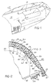
- FIGURE 1 a fragmentary view of the passenger compartment 12 of an automobile 10 is depicted, including an instrument panel 14 forming a part of the interior trim structure.
- Typical air bag systems include a separate air bag for the driver and passenger sides of the passenger compartment.
- the driver's side air bag is usually housed within a receptacle in the steering wheel and the passenger side air bag is contained within a receptacle located behind the instrument panel 14.
- the closure of the present invention may be applied to either the driver's or passenger's side, but will here be illustrated as on the passenger's side.
- a closure 16 according to the present invention is fit within an opening 18 in the instrument panel 14, the closure including an upper door 20 and a lower door 22 able to separate along a seam 24, each door hinging open upwardly and downwardly respectively to create a deployment opening through which an inflating air bag can enter the passenger compartment 12.
- the seam 24 is designed to be invisible to a person within the passenger compartment 12.
- the closure 16 includes a one piece molded substrate member 26 having an upper door portion 28 and lower door portion 30 connected along the seam 24 by an integral thin frangible bridging portion 32 extending across a gap 33 between the upper door 20 and lower door 22.
- the substrate member 26 is enclosed in a mass of foamed plastic 34 having layers extending over and under the opposite sides of the substrate member 26.
- the foamed plastic 36 extends over the gap 33.
- the substrate member 26 is relatively rigid, the upper door portion 28 and lower door portion 30 defining structural members able to effectively transfer a shearing force to the frangible bridging portion 32.
- the opening pressure is exerted by the inflating air bag 40 stored behind the closure 16, folded within a cannister 42.
- the substrate member 26 is preferably of a low density olefin plastic such as polyethylene, and a grid network is formed on the inner face by an orthogonal array of molded ribs 44 forming rectangular open compartments 46.
- a mechanical interlocking is employed to secure the mass of foamed plastic 36 to the substrate, as disclosed in detail in copending application Serial No. 07/432,559 filed on 11-06-89, Attorney Docket No. TIP-122.
- This mechanical interlock is created by injecting foamed plastic through openings 48 extending through the substrate member 26 into each compartment 46, so as to interconnect the layers of foam 36 on either side of the substrate member 26.
- the substrate member 26 is also formed with hinging sections 50, 52 integral with the portions within the upper door 20 and lower door 22 respectively.
- Each hinging section 50, 52 is attached to an opposite side of the air bag cannister 42 as with a clamping plate 54 and rivets 56.
- the hinging sections 50, 52 are formed with convoluted shape along the connected sides of the upper door 20 and lower door 22. This shape allows the doors 20, 22 to be pushed out and clear the adjacent instrument panel structure 14 prior to hinging opening of the doors 20, 22. This eliminates any interference therebetween due to the close fitting of the doors 20, 22 within the opening 18.
- the substrate member 26 is curved in conformity with the shape of the instrument panel 14, but in the region of the seam 24 is contoured with an edge 58 angled outwardly, while the mass of foam 36 and skin 38 continuously extend in that region.
- a reduced thickness of foam is located over the gap 33, and acute edges 58 assist severing of the reduced thickness of foam and the skin 38.
- the edge 58 also serves to stiffen the panel portions 28, 30, to enable effective application of the bursting pressure to the foam 36 and skin 38 at the seam.
- the substrate member 26 is formed with raised ridges 60 extending along the sides and ridges 62 along the door panel portions 28 and 30.
- the ridge 60, and the ridge 62 are raised at the seam 24 to insure initial contact with the air bag inflating from 40 to exert maximum shearing pressure on the bridging portion 32, foam 36, and skin 38 above the gap 33.
- a critical aspect of the present invention is the preweakening of the inner side of the decorative skin along the seam 24. This is accomplished by a scoring or partial cutting of the skin layer 38 to a controlled depth, indicated by the groove 66.
- a sequenced severing of the components of the seam 24 is carried out by the pressure of the inflating air bag 40 acting on the inner face of the upper and lower doors 20, 22.
- the ridges 62 pivot together and thereafter the stress applied to the bridging portions 32 causes them to break, and thereafter the thickness of foam 36 and the preweakened skin 38 is severed to allow each of the upper door 20 and lower door 22 to hinge open.
- the cut 66 is approximately one half of the total thickness of the skin layer 38.
- each door 20, 22 be sufficiently rigid to effectively transmit the shearing forces to the bridging portion 32 and the preweakened skin 38. If the doors were compliant, breakage of the frangible seam elements would be slightly delayed to adversely affect performance of the air bag system.
- the rib pattern can be made more rigid by providing additional cross ribs 70 extending diagonally as shown in FIGURE 5, across the ribs 44, with additional holes 48 enabling foam to enter each compartment 46A, 46B formed by diagonal rib 70.
- a hexagonal or octagonal rib geometry can also be employed as shown in FIGURE 6, in which angled ribs 44A create the hex or octagon shape. This likewise increases the rigidity of the substrate member 26 if necessary for a particular application.
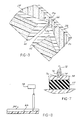
- FIGURE 7 illustrates how this can be effectively done.
- a suitable cutting blade 72 has mounted to it guide elements 74 such as rollers adapted to rest on the surface of the skin 38 as the blade 72 traverses the skin 38. The distance below the surface of the skin 38 that the cutting edge 76 protrudes corresponds to the depth of cut, and should be set accordingly.
- substantial compression of the skin material below the cutting edge 76 should be avoided in order to achieve a consistent depth.
- This requirement may be met by placing the skin 38 on a bed of a more easily compressed material than that of the skin, i.e., for example a layer of neoprene 77 rubber may be placed beneath a vinyl skin 38. This allows a slight deflection of the vinyl skin away from the cutting edge 76 to relieve excessive compression leading to erratic and inconsistent results.
- the partial cutting of the inside of the skin 38 can also be varied across the width of the disclosure, from a maximum depth at the center to a reduced depth at either side as shown in FIGURE 8. This can be done by varying the depth of the cut 66, as by a cam control 78 or other arrangement. This configuration can insure beginning of the tear at the center and propagation to either side.
- the substrate member should be stiff and thus much thicker than the skin 38, which is much thinner than the outer foam layer.
- An approximate proportion is that the skin is slightly over one half of the thickness of the substrate member 26.
- the thickness of the foam plastic layer 36 would normally be about five times the skin layer thickness, but reduced to about the same depth along the seam.
- FIGURES 9-11 depict application of the invention to a stiffened metal type of substrate member.
- a substrate member 80 is provided comprised of a formed sheet metal member 82, preferably of aluminum having an upper door panel portion 84 and a lower door panel portion 86.
- Each door panel portion 84, 86 is formed with front to back extending depressions 88 (FIGURE 11) acting to stiffen the same.
- a complementarily shaped stiffener piece of a rigid light weight plastic such as Dytherm (trademark) is affixed to the backside of substrate member 80 fit into the depressions 88, and acting to further stiffen the door panel portions 84, 86.
- Each door panel portion 84, 86 is shaped with a formed edge 81 along the adjacent sides, with a bridging portion 92 joining the same, forming a generally hat shaped raised section.
- the bridge portion 92 has slots 94 (FIGURE 11) formed along the center thereof, leaving only localized sections 96, which are further weakened by grooving 98, thus greatly weakening the bridging portion 92 of the metal layer extending along the seam between the door panel portions 84, 86.
- the stiffener piece 90 is also weakened along the seam by slots 99 and grooves 100, 102 formed into the inside and outside surface of the solid areas 97 intermediate the slots 99 thereof respectively, to substantially reduce its thickness to promote shearing along the seam.
- a layer of foam plastic 36 overlies the outside surface of the sheet metal member 82, extending continuously over the bridging section 91, 92 to be of reduced thickness at the seam.
- the foam 31 may be adhesively bonded to the metal member 82.
- a decorative skin layer 38 grooved on the inside at 66 is also provided as in the above embodiments.
- the sheet metal member 82 includes bendable hinging sections 104, 106 integral with the upper and lower door panel portions 84, 86 respectively attached to the sides op the air bag cannister 42.
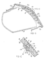
- FIGURES 12-14 show another embodiment where a completely invisible seam is achieved about the entire perimeter of an air bag deployment door panel 104 mounted in the instrument panel 14 so that the entire opening 10 is rendered invisible in a smooth expanse of the surface of the instrument panel 14.
- the door panel 104 comprises a molded plastic, substrate section 105 mounted within in the instrument panel 14 and having upper and lower horizontal flanges 106, 108 and left and right flanges 107, 109 connected to a substrate layer 110 of the instrument panel 14.
- a hinging section 112 is integral with each of the flanges 106-109, located above the respective flange 106-109 and substrate 110 to enable a respective subsection 114, 116, 118, 120 of substrate section 105 to hinge freely past the adjacent edge of the substrate 110.
- substrate section 105 could be made to be integral with the instrument panel substrate layer 110.
- the door panel subsections 114-120 are in this embodiment formed by a crossing pattern of lines of weakening 115, 117 triangular in shape, with the inwardly convergent sides contiguous to the adjacent subsections to divide the substrate section 105.
- the base of each triangular subsection 114-120 is connected to the adjacent portion of substrate member 110 by the hinging section 112. Adjacent sides of the subsections 114-120 are separated by a pair of lines of weakening arranged in a crossing pattern across the section 105 to form the triangular shape of the subsections 114-120.
- Upturned ridges 122 on either side of gaps are bridged with thin, frangible connecting webs 124 to form the lines of weakening.
- the webs 124 are chosen to be thin enough to be readily sheared by the pressure exerted by the air bag in deploy ing from the cannister 40 mounted beneath the instrument panel 14 and door panel 104, as by bracketry (not shown).
- the substrate section 105 may be attached to the instrument panel substrate 110 as by suitable fasteners 126, prior to the molding thereto of a continouous layer of foam 128 exteriorly smoothly contoured and application of a decorative skin layer 130.
- the section 105 may alternatively be of integral construction.
- the skin layer 130 is partially cut from underneath with grooves 132 extending in a pattern of crossing lines located aligned with and matching the pattern of weakening webs 124 forming.
- the grooves 132 in the skin 130 are formed as described above.
- the reduced foam thickness above the webs 124 and the skin prescoring groove 132 create an exteriorly invisible frangible seams between subsections 114-120.
- the door panel subsections 114-120 are split apart at the lines of weakening, and hinged back to be able to be forced open in flower petal fashion, exposing the opening 10 in the instrument panel substrate member 110 to allow the air bag to deploy therethrough.
- the crossing pattern of the lines of weakening creates maximum weakness at the center to initiate tearing at this point, and provides an infinite radius at the "corners" which no longer exist.
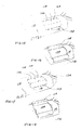
- a minimally radiused corner may also be employed depending on the pliability of the covering material and the ease with which it may be torn, as shown in FIGURES 15 and 16.
- other patterns may be employed, such as opposing curved vee patterns either coming together at a point or connected by a horizontal line 134 of varying lengths as shown in FIGURES 17 and 18.
- this embodiment allows a completely invisible air bag deployment door panel to be provided as a part of the instrument panel, to deter tampering and improving the appearance of the interior trim.
Abstract
Description
- This invention concerns an arrangement for providing air bag deployment openings in interior trim structure. Inflatable cushion devices (commonly referred to as "air bags") have been devised for automotive vehicles, in which one or more air bags are stowed in respective storage spaces located within the passenger compartment. Typically a driver's side air bag is stored in a compartment in the center of the steering wheel and a passenger's side air bag is stored in a compartment behind the instrument panel. Upon detection of a relatively severe collision, the air bag or bags are very rapidly inflated to be deployed in positions to cushion the driver and/or passengers from injury-causing contact with the interior structure of the auto.
- The air bags must be neatly stowed out of sight and so as to be resistant to tampering, yet able to deploy into the passenger compartment in an instant. This requires a sturdy closure panel for the deployment open ing, which preferably minimizes the visual impression of the presence of the closure, and yet reliably opens under the wide range of ambient temperature conditions for which the auto is designed for use, over the entire useful life of the car.
- Such closures are usually opened by the force exerted by the inflating air bag, and the development of the air bag must not be appreciably slowed by under resistance to the opening of the closure. The considerable force applied by the inflating air bag must not result in fragmentation or separation of the closure, lest debris be projected towards persons in the passenger compartment.
- The closure is of necessity exposed within the auto interior, and thus must be aesthetically compatible with the auto interior trim.
- A vinyl skin covering is commonly applied to the instrument panel and other trim panel surfaces. Plastics such as vinyl while durable are relatively tough and resistant to tearing.
- There has heretofore been proposed such closures in which doors are formed by a substrate panel overlain by a vinyl skin, with the skin ruptured by the deploying air bag forcing the substrate panels open. While preweakening of the skin has been utilized to facilitate tearing, it is difficult to achieve reliable tearing at the appropriate force level. U.S. patent 3,640,546 discloses a closure in which a air of doors are covered by a covering skin, preweakened along a line of separation; which is ruptured when the doors are forced opened by the deploying air bag. The line of weakening is described as being accomplished by a reduction in thickness, perforating, or of heating. Such a joint is not sufficiently sturdy to resist inward pressure applied to an occupant and also results in a visible seam. Furthermore, a consistent control over the depth of cut when scoring vinyl is not easily obtained, and a proper bursting strength is difficult to reliably achieve in production.
- Other approaches have included positioning piercing pieces forced into the skin to initiate tearing action, but this creates a complicated design.
- The present invention comprises a combination of upper and lower rigid door panel portions formed in a substrate member, each door panel supported on hinging sections extending along the sides remote from each other. A thin frangible bridging portion of the substrate member extends across the gap between the adjacent sides of the upper and lower door panel portions to form a seam. A layer of foam overlies both door panel portions extending across the seam, and a decorative skin overlies the foam layer. The skin is scored from the inside to a consistently controlled depth along the seam. A successive breaking of the bridging portion, foam layer and scored skin at the seam is achieved as the deploying door exerts an outward pressure on the panel portions.
- A network of ribs stiffens the door panels to insure proper exertion of pressure at the seam, and a raised edge along the seam insure that an adequate force is applied by the door panel portions to the frangible structure along the seam. Also, the foam thickness is reduced at the seam by the raised contouring of the adjacent edge of each door panel.
- In a first version, the substrate member is formed by a molded rigid plastic, having an integral thin web forming the bridging portions.
- In a second version, the substrate member is comprised of formed metal such as aluminum having a thick piece of a lightweight rigid foam plastic such as Dytherm plastic attached to each door panel portion to stiffen the substrate and provide a raised contact surface for engagement by the air bag. In this second version, narrowed sections of the rigid foam plastic piece and areas of the metal intermediate slots extending along the seam comprise the bridging portions.
- This construction allows a low cost, durable closure construction which is well matched to adjacent trim structure and has a well supported invisible parting seam, and which insures reliable opening under pressure from an inflating air bag.
- A special skin scoring method is employed to establigh consistent control over the depth of the score, comprised of supporting the skin on a compressible support bed during scoring, passing a scoring knife through the inside of the skin which guiding the knife on guide elements moving along while head against the inside surface. The compressible support bed allows relief of compressive stresses otherwise imposed on the skin material to insure a uniform scoring depth.
- The present invention also comprises an arrangement for forming an opening in an interior trim structure including a substrate member. The arrangement includes a door panel substrate section connection either integrally or separately to the interior trim substrate member.
- A pattern of lines of weakening in the substrate section divide it into subsections contiguous with each other. The sides contiguous with the adjacent trim structure substrate member form hinging sections.
- A smooth layer of foam overlies both the substrate member and door panel substrate section, with a decorative skim overlying both, scored from the inside in a pattern matching the lines of weakening in the substrate section to form an exteriorly invisible frangible seam in the trim structure.
- The pressure exerted by the deploying air bag splits the seams and allows the subsections to fold back and form a deployment opening.
-
- FIGURE 1 is a fragmentary perspective view of an auto interior with an instrument panel formed with an air bag deployment opening closure according to the present invention.
- FIGURE 2 is an enlarged fragmentary transverse sectional view taken through the closure and adjacent instrument panel structure shown in FIGURE 1.
- FIGURE 3 is a further enlarged transverse sectional view through the panels showing the details of the seam.
- FIGURE 4 is a perspective view of a one piece molded door panel substrate member assembly incorporated in the door panels shown in FIGURES 1-3.
- FIGURE 5 is a fragmentary plan view of an alternate construction of the door panel substrate member.
- FIGURE 6 is a fragmentary plan view of yet another alternate embodiment of the door panel substrate member.
- FIGURE 7 is a greatly enlarged transverse sectional view of vinyl skin material undergoing scoring the inside surface prior to assembly into the closure according to the present invention.
- FIGURE 8 is a fragmentary lengthwise view of a scored section of skin showing a varied depth scoring across the width of the closure.
- FIGURE 9 is a transverse sectional view taken through an alternate embodiment of a closure according to the present invention.
- FIGURE 10 is an enlarged view of the region of the closure shown in FIGURE 9 adjacent the seam.
- FIGURE 11 is a fragmentary rear plan view of the formed sheet metal element incorporated in the closure shown in FIGURE 9 and 10.
- FIGURE 12 is a perspective fragmentary view of an instrument panel incorporating an arrangement of an air bag deployment opening closure according to the present invention.
- FIGURE 13 is an enlarged view of the section 13-13 taken in FIGURE 12.
- FIGURE 14 is a perspective fragmentary view of the instrument panel shown in FIGURE 12 with the closure opened.
- FIGURE 15 is a fragmentary perspective view of an instrument panel having an air bag opening closure according to another form of the present invention.
- FIGURE 16 is a fragmentary view of the closure shown in FIGURE 15, in the opened condition.
- FIGURE 17 is a fragmentary perspective view of an instrument panel having an air bag opening closure according to yet another form of the present invention.
- FIGURE 18 is a view of the closure shown in FIGURE 17 in the open condition.
- In the following detailed description, certain specific terminology will be employed for the sake of clarity and a particular embodiment described in accordance with the requirements of 35 USC 112, but it is to be understood that the same is not to be limiting and should not be so construed inasmuch as the invention is capable of taking many forms and variations within the scope of the appended claims.
- Referring to FIGURE 1, a fragmentary view of the
passenger compartment 12 of an automobile 10 is depicted, including aninstrument panel 14 forming a part of the interior trim structure. Typical air bag systems include a separate air bag for the driver and passenger sides of the passenger compartment. The driver's side air bag is usually housed within a receptacle in the steering wheel and the passenger side air bag is contained within a receptacle located behind theinstrument panel 14. The closure of the present invention may be applied to either the driver's or passenger's side, but will here be illustrated as on the passenger's side. - A
closure 16 according to the present invention is fit within anopening 18 in theinstrument panel 14, the closure including anupper door 20 and alower door 22 able to separate along aseam 24, each door hinging open upwardly and downwardly respectively to create a deployment opening through which an inflating air bag can enter thepassenger compartment 12. - As will be described, the
seam 24 is designed to be invisible to a person within thepassenger compartment 12. - Referring to FIGURES 2 and 3, the
closure 16 includes a one piece moldedsubstrate member 26 having anupper door portion 28 andlower door portion 30 connected along theseam 24 by an integral thinfrangible bridging portion 32 extending across agap 33 between theupper door 20 andlower door 22. - The
substrate member 26 is enclosed in a mass of foamed plastic 34 having layers extending over and under the opposite sides of thesubstrate member 26. The foamedplastic 36 extends over thegap 33. - A
decorative skin layer 38 as of thin, flexible vinyl plastic sheet, is wrapped and bonded (by the heat of injection of the foam 36) in position overlying the outside layer of foam plastic deposited over bothupper door 20 andlower door 22, extending over theseam 24. Since theskin layer 38 is supported by thefoam 36 along theseam 24, theseam 24 will be invisible to an occupant of the auto. - The
substrate member 26 is relatively rigid, theupper door portion 28 andlower door portion 30 defining structural members able to effectively transfer a shearing force to thefrangible bridging portion 32. The opening pressure is exerted by the inflatingair bag 40 stored behind theclosure 16, folded within acannister 42. - The
substrate member 26 is preferably of a low density olefin plastic such as polyethylene, and a grid network is formed on the inner face by an orthogonal array of moldedribs 44 forming rectangular open compartments 46. - Since it is difficult to securely bond foamed plastic to low density olefin plastics such as polyethelene, a mechanical interlocking is employed to secure the mass of foamed plastic 36 to the substrate, as disclosed in detail in copending application Serial No. 07/432,559 filed on 11-06-89, Attorney Docket No. TIP-122. This mechanical interlock is created by injecting foamed plastic through
openings 48 extending through thesubstrate member 26 into eachcompartment 46, so as to interconnect the layers offoam 36 on either side of thesubstrate member 26. - The
substrate member 26 is also formed with hingingsections 50, 52 integral with the portions within theupper door 20 andlower door 22 respectively. - Each hinging
section 50, 52 is attached to an opposite side of theair bag cannister 42 as with a clampingplate 54 and rivets 56. The hingingsections 50, 52 are formed with convoluted shape along the connected sides of theupper door 20 andlower door 22. This shape allows thedoors instrument panel structure 14 prior to hinging opening of thedoors doors opening 18. - The
substrate member 26 is curved in conformity with the shape of theinstrument panel 14, but in the region of theseam 24 is contoured with an edge 58 angled outwardly, while the mass offoam 36 andskin 38 continuously extend in that region. Thus, a reduced thickness of foam is located over thegap 33, and acute edges 58 assist severing of the reduced thickness of foam and theskin 38. The edge 58 also serves to stiffen thepanel portions foam 36 andskin 38 at the seam. - The
substrate member 26 is formed with raised ridges 60 extending along the sides andridges 62 along thedoor panel portions ridge 62 are raised at theseam 24 to insure initial contact with the air bag inflating from 40 to exert maximum shearing pressure on the bridgingportion 32,foam 36, andskin 38 above thegap 33. - A critical aspect of the present invention is the preweakening of the inner side of the decorative skin along the
seam 24. This is accomplished by a scoring or partial cutting of theskin layer 38 to a controlled depth, indicated by thegroove 66. - A sequenced severing of the components of the
seam 24 is carried out by the pressure of the inflatingair bag 40 acting on the inner face of the upper andlower doors - The
ridges 62 pivot together and thereafter the stress applied to the bridgingportions 32 causes them to break, and thereafter the thickness offoam 36 and thepreweakened skin 38 is severed to allow each of theupper door 20 andlower door 22 to hinge open. In a typical application, thecut 66 is approximately one half of the total thickness of theskin layer 38. - It is important that each
door portion 32 and thepreweakened skin 38. If the doors were compliant, breakage of the frangible seam elements would be slightly delayed to adversely affect performance of the air bag system. - The rib pattern can be made more rigid by providing
additional cross ribs 70 extending diagonally as shown in FIGURE 5, across theribs 44, withadditional holes 48 enabling foam to enter eachcompartment diagonal rib 70. - A hexagonal or octagonal rib geometry can also be employed as shown in FIGURE 6, in which angled
ribs 44A create the hex or octagon shape. This likewise increases the rigidity of thesubstrate member 26 if necessary for a particular application. - It is critical that the partial cutting of the inside of the
skin 38 be consistently held to the designed for depth. FIGURE 7 illustrates how this can be effectively done. Asuitable cutting blade 72 has mounted to it guideelements 74 such as rollers adapted to rest on the surface of theskin 38 as theblade 72 traverses theskin 38. The distance below the surface of theskin 38 that thecutting edge 76 protrudes corresponds to the depth of cut, and should be set accordingly. - According to one aspect of this method, substantial compression of the skin material below the
cutting edge 76 should be avoided in order to achieve a consistent depth. This requirement may be met by placing theskin 38 on a bed of a more easily compressed material than that of the skin, i.e., for example a layer ofneoprene 77 rubber may be placed beneath avinyl skin 38. This allows a slight deflection of the vinyl skin away from thecutting edge 76 to relieve excessive compression leading to erratic and inconsistent results. - The partial cutting of the inside of the
skin 38 can also be varied across the width of the disclosure, from a maximum depth at the center to a reduced depth at either side as shown in FIGURE 8. This can be done by varying the depth of thecut 66, as by acam control 78 or other arrangement. This configuration can insure beginning of the tear at the center and propagation to either side. - As noted above, the substrate member should be stiff and thus much thicker than the
skin 38, which is much thinner than the outer foam layer. An approximate proportion is that the skin is slightly over one half of the thickness of thesubstrate member 26. The thickness of thefoam plastic layer 36 would normally be about five times the skin layer thickness, but reduced to about the same depth along the seam. - FIGURES 9-11 depict application of the invention to a stiffened metal type of substrate member. In this embodiment, a
substrate member 80 is provided comprised of a formedsheet metal member 82, preferably of aluminum having an upperdoor panel portion 84 and a lowerdoor panel portion 86. Eachdoor panel portion substrate member 80 fit into thedepressions 88, and acting to further stiffen thedoor panel portions door panel portion portion 92 joining the same, forming a generally hat shaped raised section. Thebridge portion 92 has slots 94 (FIGURE 11) formed along the center thereof, leaving only localized sections 96, which are further weakened by grooving 98, thus greatly weakening the bridgingportion 92 of the metal layer extending along the seam between thedoor panel portions - The
stiffener piece 90 is also weakened along the seam byslots 99 andgrooves solid areas 97 intermediate theslots 99 thereof respectively, to substantially reduce its thickness to promote shearing along the seam. - As in the above described embodiment, a layer of
foam plastic 36 overlies the outside surface of thesheet metal member 82, extending continuously over the bridgingsection 91, 92 to be of reduced thickness at the seam. The foam 31 may be adhesively bonded to themetal member 82. Adecorative skin layer 38 grooved on the inside at 66 is also provided as in the above embodiments. - The
sheet metal member 82 includesbendable hinging sections door panel portions air bag cannister 42. - FIGURES 12-14 show another embodiment where a completely invisible seam is achieved about the entire perimeter of an air bag
deployment door panel 104 mounted in theinstrument panel 14 so that the entire opening 10 is rendered invisible in a smooth expanse of the surface of theinstrument panel 14. - The
door panel 104 comprises a molded plastic,substrate section 105 mounted within in theinstrument panel 14 and having upper and lowerhorizontal flanges right flanges 107, 109 connected to asubstrate layer 110 of theinstrument panel 14. Ahinging section 112 is integral with each of the flanges 106-109, located above the respective flange 106-109 andsubstrate 110 to enable arespective subsection substrate section 105 to hinge freely past the adjacent edge of thesubstrate 110. - Alternatively,
substrate section 105 could be made to be integral with the instrumentpanel substrate layer 110. - In order to completely eliminate the right angle corners which require considerable energy to tear around, the door panel subsections 114-120 are in this embodiment formed by a crossing pattern of lines of weakening 115, 117 triangular in shape, with the inwardly convergent sides contiguous to the adjacent subsections to divide the
substrate section 105. The base of each triangular subsection 114-120 is connected to the adjacent portion ofsubstrate member 110 by thehinging section 112. Adjacent sides of the subsections 114-120 are separated by a pair of lines of weakening arranged in a crossing pattern across thesection 105 to form the triangular shape of the subsections 114-120. Upturnedridges 122 on either side of gaps are bridged with thin, frangible connectingwebs 124 to form the lines of weakening. Thewebs 124 are chosen to be thin enough to be readily sheared by the pressure exerted by the air bag in deploy ing from thecannister 40 mounted beneath theinstrument panel 14 anddoor panel 104, as by bracketry (not shown). - The
substrate section 105 may be attached to theinstrument panel substrate 110 as by suitable fasteners 126, prior to the molding thereto of a continouous layer offoam 128 exteriorly smoothly contoured and application of adecorative skin layer 130. As noted, thesection 105 may alternatively be of integral construction. - The
skin layer 130 is partially cut from underneath withgrooves 132 extending in a pattern of crossing lines located aligned with and matching the pattern of weakeningwebs 124 forming. - The
grooves 132 in theskin 130 are formed as described above. Thus, the reduced foam thickness above thewebs 124 and theskin prescoring groove 132 create an exteriorly invisible frangible seams between subsections 114-120. - Upon system activation, the door panel subsections 114-120 are split apart at the lines of weakening, and hinged back to be able to be forced open in flower petal fashion, exposing the opening 10 in the instrument
panel substrate member 110 to allow the air bag to deploy therethrough. - The crossing pattern of the lines of weakening creates maximum weakness at the center to initiate tearing at this point, and provides an infinite radius at the "corners" which no longer exist. A minimally radiused corner may also be employed depending on the pliability of the covering material and the ease with which it may be torn, as shown in FIGURES 15 and 16. Thus, other patterns may be employed, such as opposing curved vee patterns either coming together at a point or connected by a
horizontal line 134 of varying lengths as shown in FIGURES 17 and 18. - It will be appreciated that this embodiment allows a completely invisible air bag deployment door panel to be provided as a part of the instrument panel, to deter tampering and improving the appearance of the interior trim.
- Accordingly, a reliably operating mechanical break for a skin encased closure has been provided by the closure described to achieve the advantages of the invention as described above.
Claims (19)
a substrate member (26) having an upper and lower door panel portions (28, 30), said portions having adjacent sides separated by a gap (33), with a frangible bridging portion (32) connecting said upper and lower door panel portions extending across said gap (33);
a skin (38) overlying said substrate member (26), extending across said door panel portions (28, 30) and said gap (33) therebetween, said skin (38) partially cut from the inside along said gap (33), whereby said bridging portion (32) and said partially cut skin (38) form a frangible seam (24) between said upper and lower door panel portions (28, 30).
drawing a cutting blade along the upper surface of said plastic sheet layer along said line at a predetermined depth in said layer, whereby any compression of said layer is relieved by deflection of said support bed material.
a generally rectangular door panel including a substrate section connected to said interior trim sub strate member, said substrate section divided into a plurality of contiguous subsections, said subsections having adjacent sides separated by a line of weakening, with frangible bridging portions connecting said contiguous portions of said subsections;
a flange portion on one side of each subsection connected to said interior trim substrate member to enable all of said subsections to hinge away from said substrate member and form an opening therein;
a skin overlying said trim structure substrate member, extending over said opening and said substrate member, said skin partially cut from the inside in a pattern matching and aligned with said pattern of lines of weakening in said substrate section, whereby said bridging portions and said partially cut skin form a pattern of frangible seams allowing said subsections to be split apart and forced out to form said opening and allow deployment of an air bag therethrough.
Priority Applications (1)
| Application Number | Priority Date | Filing Date | Title |
|---|---|---|---|
| EP95101254A EP0661142B1 (en) | 1989-11-06 | 1990-11-06 | A method of cutting a compressible plastic sheet layer |
Applications Claiming Priority (4)
| Application Number | Priority Date | Filing Date | Title |
|---|---|---|---|
| US43255989A | 1989-11-06 | 1989-11-06 | |
| US432559 | 1989-11-06 | ||
| US07/541,132 US5082310A (en) | 1989-11-06 | 1990-06-20 | Arrangement for providing an air bag deployment opening |
| US541132 | 2000-03-31 |
Related Child Applications (1)
| Application Number | Title | Priority Date | Filing Date |
|---|---|---|---|
| EP95101254.1 Division-Into | 1990-11-06 |
Publications (3)
| Publication Number | Publication Date |
|---|---|
| EP0428935A2 true EP0428935A2 (en) | 1991-05-29 |
| EP0428935A3 EP0428935A3 (en) | 1991-09-25 |
| EP0428935B1 EP0428935B1 (en) | 1995-09-13 |
Family
ID=27029550
Family Applications (2)
| Application Number | Title | Priority Date | Filing Date |
|---|---|---|---|
| EP95101254A Expired - Lifetime EP0661142B1 (en) | 1989-11-06 | 1990-11-06 | A method of cutting a compressible plastic sheet layer |
| EP90121216A Expired - Lifetime EP0428935B1 (en) | 1989-11-06 | 1990-11-06 | Arrangement for providing an air bag deployment opening |
Family Applications Before (1)
| Application Number | Title | Priority Date | Filing Date |
|---|---|---|---|
| EP95101254A Expired - Lifetime EP0661142B1 (en) | 1989-11-06 | 1990-11-06 | A method of cutting a compressible plastic sheet layer |
Country Status (5)
| Country | Link |
|---|---|
| US (1) | US5082310A (en) |
| EP (2) | EP0661142B1 (en) |
| JP (1) | JP3009208B2 (en) |
| CA (1) | CA2029364C (en) |
| DE (2) | DE69033765T2 (en) |
Cited By (33)
| Publication number | Priority date | Publication date | Assignee | Title |
|---|---|---|---|---|
| US5154444A (en) * | 1991-04-05 | 1992-10-13 | Davidson Textron Inc. | Air bag retainer with cutting flaps |
| EP0520537A1 (en) * | 1991-06-25 | 1992-12-30 | KOLBENSCHMIDT Aktiengesellschaft | Passenger restraint device |
| US5195773A (en) * | 1990-05-24 | 1993-03-23 | Takata Corporation | Cover for accommodating an air bag |
| EP0588176A2 (en) * | 1992-09-16 | 1994-03-23 | Toyoda Gosei Co., Ltd. | A pad for use in an air bag device |
| GB2276354A (en) * | 1993-03-22 | 1994-09-28 | Klippan Autoliv Snc | A cover for a vehicle air-bag |
| EP0619204A2 (en) * | 1993-04-08 | 1994-10-12 | Volkswagen Aktiengesellschaft | Airbag |
| GB2277908A (en) * | 1993-05-11 | 1994-11-16 | Autoliv Dev | Vehicle air-bag arrangement |
| WO1995000367A1 (en) * | 1993-06-21 | 1995-01-05 | Autoliv Development Ab | A cover for an air-bag |
| EP0646501A1 (en) * | 1993-10-05 | 1995-04-05 | Tip Engineering Group, Inc. | Invisible seam deployment door installation with stabilized air bag deployment opening construction |
| DE4344523A1 (en) * | 1993-12-24 | 1995-07-20 | Ymos Ag Ind Produkte | Airbag chamber cover |
| WO1995024328A1 (en) * | 1994-03-10 | 1995-09-14 | Autoliv Development Ab | An air-bag arrangement |
| EP0675026A1 (en) * | 1994-03-29 | 1995-10-04 | Adam Opel Ag | Air bag cover |
| EP0680852A2 (en) * | 1994-05-02 | 1995-11-08 | Morton International, Inc. | Fastenerless tethered deployment door for passenger-side airbag module |
| EP0684168A1 (en) * | 1994-05-25 | 1995-11-29 | Morton International, Inc. | Arrangement for providing an airbag deployment opening |
| FR2721876A1 (en) * | 1994-06-30 | 1996-01-05 | Ecia Equip Composants Ind Auto | Covering panel for vehicle air bag unit |
| FR2721878A1 (en) * | 1994-06-30 | 1996-01-05 | Ecia Equip Composants Ind Auto | Stowage cover for air bags in vehicle structure |
| FR2721877A1 (en) * | 1994-06-30 | 1996-01-05 | Ecia Equip Composants Ind Auto | Cover for air bag concealed in e.g. bodywork panel of motor vehicle |
| DE19516230A1 (en) * | 1995-05-03 | 1996-11-07 | Eldra Kunststofftechnik Gmbh | Airbag cover and process for its manufacture |
| EP0714817A3 (en) * | 1994-12-01 | 1996-11-13 | Morton Int Inc | Invisible instrument panel or dashboard airbag cover door |
| WO1998049033A1 (en) * | 1997-04-28 | 1998-11-05 | Petri Ag | Airbag covering cap comprising a support layer and a cover layer of different elasticities |
| FR2768675A1 (en) * | 1997-09-19 | 1999-03-26 | Reydel Sa | Interior equipment for motor vehicle retaining inflatable bag |
| WO2000010840A1 (en) | 1998-08-25 | 2000-03-02 | Eldra Kunststofftechnik Gmbh | Decorative layer for an air bag covering |
| WO2000051851A1 (en) * | 1999-03-01 | 2000-09-08 | Takata-Petri Ag | Tear-off strip in coverings of airbag units |
| WO2001060664A1 (en) * | 2000-02-15 | 2001-08-23 | Textron Automotive Company Inc. | Vehicle airbag door having three layers with three respective partial mechanical weakness lines |
| EP1216894A1 (en) * | 2000-12-21 | 2002-06-26 | Delphi Technologies, Inc. | Instrument panel with integral hidden airbag door cover and method of in-process manufacture thereof |
| EP1251039A1 (en) * | 2001-04-20 | 2002-10-23 | Sanko Gosei Kabushiki Kaisha | Airbag apparatus |
| EP1149742A3 (en) * | 2000-04-26 | 2003-03-19 | Sanko Gosei Kabushiki Kaisha | Airbag apparatus |
| EP1348600A1 (en) * | 2002-03-29 | 2003-10-01 | Calsonic Kansei Corporation | Cover structure for air bag device |
| US6976701B2 (en) | 2000-02-15 | 2005-12-20 | Collins & Aikman Automotive Company Inc. | Airbag door and method for making same |
| DE10020525B4 (en) * | 2000-04-27 | 2007-11-22 | Lisa Dräxlmaier GmbH | airbag cover |
| EP1970183A3 (en) * | 2007-03-12 | 2008-11-05 | GM Global Technology Operations, Inc. | Hidden airbag flap, device and method for its production |
| DE19829752B4 (en) * | 1998-07-03 | 2012-01-19 | Quin Gmbh | Airbag cover |
| CN109451736A (en) * | 2016-06-30 | 2019-03-08 | 上海延锋金桥汽车饰件系统有限公司 | Decorative element for vehicle interior |
Families Citing this family (148)
| Publication number | Priority date | Publication date | Assignee | Title |
|---|---|---|---|---|
| US5744776A (en) * | 1989-07-14 | 1998-04-28 | Tip Engineering Group, Inc. | Apparatus and for laser preweakening an automotive trim cover for an air bag deployment opening |
| US5611564A (en) * | 1993-08-18 | 1997-03-18 | Tip Engineering Group, Inc. | Method and treatment for forming an air bag deployment opening in leather covered trim |
| JP3006069B2 (en) * | 1990-10-26 | 2000-02-07 | タカタ株式会社 | Module cover for airbag device |
| US5222760A (en) * | 1990-12-07 | 1993-06-29 | Davidson Textron Inc. | Decorative panel with invisible tear seam |
| JPH0558517U (en) * | 1992-01-23 | 1993-08-03 | 三ツ星ベルト株式会社 | instrument panel |
| US5456490A (en) * | 1992-08-13 | 1995-10-10 | Davidson Textron Inc. | Hidden door for an air bag restraint system |
| US5335935A (en) * | 1992-08-31 | 1994-08-09 | Plastic Mold Technology Incorporated | Air bag cover/molded article with integral cover layer of leather |
| DE4229379C2 (en) * | 1992-09-03 | 1996-03-28 | Daimler Benz Ag | Cover for the gas cushion of an impact protection device for vehicle occupants |
| US5288103A (en) * | 1992-09-28 | 1994-02-22 | Davidson Textron Inc. | Airbag cover and apparatus for producing an invisible tear seam therein |
| US5256354A (en) * | 1992-11-12 | 1993-10-26 | Davidson Textron Inc. | Method for forming an invisible tear seam |
| US5378014A (en) * | 1992-11-13 | 1995-01-03 | Davidson Textron Inc. | Dual door arrangement for air bag deployment |
| US5443777A (en) * | 1992-12-04 | 1995-08-22 | Davidson Textron Inc. | Method for producing an invisible tear seam for an air bag deployment opening cover |
| US5390950A (en) * | 1993-03-04 | 1995-02-21 | Tip Eng Group Inc | Method and arrangement for forming an air bag deployment opening in an auto interior trim piece |
| US5437470A (en) * | 1993-04-02 | 1995-08-01 | Nissan Motor Co., Ltd. | Air bag lid structure including a main lid and a sub lid |
| US5342086A (en) * | 1993-05-03 | 1994-08-30 | Morton International, Inc. | Closure for an inflatable restraint system |
| US5382047A (en) * | 1993-07-14 | 1995-01-17 | Davidson Textron | Supplemental inflatable restraint cover assembly with a perforated substrate |
| US5460403A (en) * | 1993-08-03 | 1995-10-24 | Morton International, Inc. | Inflatable air bag module |
| US5322324A (en) * | 1993-08-03 | 1994-06-21 | Morton International, Inc. | Cover for an inflatable air bag housing |
| US5407225A (en) * | 1993-08-19 | 1995-04-18 | Davidson Textron | Invisible airbag door having reinforced PVC shell |
| US5458361A (en) * | 1993-08-25 | 1995-10-17 | Davidson Textron Inc. | Insert for air bag cover assembly |
| US5393089A (en) * | 1993-09-01 | 1995-02-28 | Chrysler Corporation | Vehicle air bag cover |
| US5342088A (en) * | 1993-10-05 | 1994-08-30 | Tip Engineering Group | Deployment door patterns for an air bag safety system |
| US5340149A (en) * | 1993-12-27 | 1994-08-23 | Davidson Textron Inc. | Door assembly with integral tether |
| DE4413416A1 (en) * | 1994-04-18 | 1995-06-29 | Daimler Benz Ag | Inflatable gas=bag cover in vehicle |
| US5433474A (en) * | 1994-05-13 | 1995-07-18 | Davidson Textron, Inc. | Air bag cover assembly |
| DE4417952A1 (en) * | 1994-05-21 | 1995-11-23 | Petri Ag | Cover for gas bag impact protection devices and process for their manufacture |
| US5445410A (en) * | 1994-06-13 | 1995-08-29 | Chrysler Corporation | Instrument panel assembly having hidden air bag door disposed laterally between vents |
| US5451075A (en) * | 1994-06-29 | 1995-09-19 | Davidson Textron Inc. | Closure for an air bag assembly |
| US5569959A (en) | 1994-06-29 | 1996-10-29 | David Textron, Inc. | Closure for an air bag assembly |
| US5478106A (en) * | 1994-07-22 | 1995-12-26 | Tip Engineering Group, Inc. | Method and arrangement for forming an air bag deployment opening |
| US5460401A (en) * | 1994-08-05 | 1995-10-24 | Morton International, Inc. | Airbag system with tethered cover |
| US6053527A (en) * | 1994-08-05 | 2000-04-25 | Autoliv Asp, Inc. | Airbag system with serviceable tethered cover |
| US5472228A (en) * | 1994-08-05 | 1995-12-05 | Morton International, Inc. | Break-away fastening system for air bag deployment doors |
| US5456487A (en) * | 1994-08-22 | 1995-10-10 | Chrysler Corporation | Passenger air bag door |
| US5590901A (en) * | 1994-09-14 | 1997-01-07 | The Goodyear Tire & Rubber Company | Method and apparatus for vehicle trim panel having hidden air bag door |
| JP3439847B2 (en) * | 1994-09-16 | 2003-08-25 | 株式会社イノアックコーポレーション | Automotive airbag door structure |
| US5431435A (en) * | 1994-09-26 | 1995-07-11 | Davidson Textron Inc. | Door panel air bag cover |
| US5496059A (en) * | 1994-10-26 | 1996-03-05 | Tip Engineering Group, Inc. | Air bag installation using integrated energy device to form trim piece air bag deployment openings |
| US5626357A (en) * | 1994-11-17 | 1997-05-06 | Morton International, Inc. | Passenger airbag module using an essentially unitary cover |
| US5466000A (en) * | 1994-11-17 | 1995-11-14 | Morton International, Inc. | Flat-lying cutter/ripper foldable into upstanding position during deployment of a vehicle airbag for detaching a deployment door from a panel |
| US5861077A (en) * | 1994-12-21 | 1999-01-19 | Seiko Epson Corporation | Separation method for adhesive sheet and its device |
| JPH08229887A (en) * | 1994-12-27 | 1996-09-10 | Seiko Epson Corp | Laminated sheet cutting method and device thereof |
| US5560646A (en) * | 1995-04-24 | 1996-10-01 | Davidson Textron | Air bag door arrangement |
| US5613701A (en) * | 1995-05-16 | 1997-03-25 | Morton International Inc. | Break-away fastening system for air bag deployment doors |
| US5632914A (en) * | 1995-05-24 | 1997-05-27 | Davidson Textron Inc. | Motor vehicle air bag cover having a skin with a virtually invisible tear seam formed by miniature holes |
| US5681051A (en) * | 1995-06-05 | 1997-10-28 | Trw Vehicle Safety Systems Inc. | Deployment door assembly |
| US5615908A (en) * | 1995-06-07 | 1997-04-01 | Trw Vehicle Safety Systems Inc. | Deployment door assembly |
| US5549324A (en) * | 1995-07-11 | 1996-08-27 | Davidson Textron Inc. | Construction and method of forming a door assembly for an air system |
| DE19528627C1 (en) * | 1995-08-04 | 1996-10-24 | Audi Ag | Passenger restraining system for back seat of motor vehicle |
| DE19633034B8 (en) * | 1995-08-25 | 2016-05-19 | Volkswagen Ag | Occupant side protection and seat cover for a motor vehicle |
| US5792413A (en) * | 1995-08-31 | 1998-08-11 | Chrysler Corporation | Top cover for instrument panel with seamless air bag door and method of manufacture |
| US5533749A (en) * | 1995-09-07 | 1996-07-09 | Morton International, Inc. | Apparatus for improved detachment of the deployment door of an airbag assembly |
| US5584502A (en) * | 1995-09-21 | 1996-12-17 | Trw Vehicle Safety Systems Inc. | Deployment door assembly |
| US5590903A (en) * | 1995-09-29 | 1997-01-07 | Trw Vehicle Safety Systems, Inc. | Deployment door assembly |
| US5630613A (en) * | 1995-10-23 | 1997-05-20 | Morton International, Inc. | Apparatus for aiding in the opening of an integral deployment door in a panel of an airbag assembly |
| EP0857123B1 (en) * | 1995-11-09 | 2003-07-09 | Textron Automotive Company Inc. | Air bag tear seam and method of manufacture |
| US5639115A (en) * | 1995-12-12 | 1997-06-17 | Trw Vehicle Safety Systems Inc. | Deployment door assembly for an inflatable vehicle occupant restraint |
| DE19616942B4 (en) * | 1996-04-27 | 2005-06-16 | Mst Automotive Gmbh Automobil-Sicherheitstechnik | Airbag cover |
| US6164686A (en) * | 1996-08-26 | 2000-12-26 | The Goodyear Tire & Rubber Company | Instrument panel passenger side air bag door |
| DE19646548C2 (en) * | 1996-10-31 | 1998-08-27 | Sommer Allibert Lignotock Gmbh | Interior trim part for motor vehicles with airbag equipment |
| EP1232912B1 (en) * | 1996-11-07 | 2005-01-12 | Toyota Jidosha Kabushiki Kaisha | Arrangement and construction of crew protective device for automobile |
| US5893581A (en) * | 1996-11-22 | 1999-04-13 | General Motors Corporation | Air bag cover |
| US5810388A (en) * | 1997-01-16 | 1998-09-22 | Ford Motor Company | Instrument panel air bag door and method of making thereof |
| US6524505B1 (en) * | 1997-01-20 | 2003-02-25 | Allibert Industrie | Method for making a finished part comprising a zone for providing a passage |
| US5762363A (en) * | 1997-01-21 | 1998-06-09 | Ford Global Technologies, Inc. | Seamless side inflatable restraint deployment system |
| AU749401B2 (en) * | 1997-02-19 | 2002-06-27 | Toyo Tire & Rubber Co., Ltd. | Instrument panel for air bag |
| CN100374328C (en) | 1997-03-26 | 2008-03-12 | 丰田自动车株式会社 | Interior member having airbag door section for use in vehicles, and its molding method |
| US5899488A (en) * | 1997-03-26 | 1999-05-04 | Inova Gmbh Technische Entwicklungen | Air bag arrangement and triggering process therefor |
| US6523854B1 (en) * | 1998-05-27 | 2003-02-25 | Volkswagen Ag | Vehicle part with an airbag device and method for producing a vehicle part of this type |
| US5957484A (en) * | 1998-06-02 | 1999-09-28 | Breed Automotive Technology, Inc. | Airbag tear seam |
| FR2782302B1 (en) * | 1998-08-13 | 2000-10-06 | Sommer Allibert Lignotock | DASHBOARD EQUIPPED WITH AN INFLATABLE SAFETY CUSHION DISPOSED IN A CASE |
| DE19847386A1 (en) * | 1998-10-14 | 1999-09-23 | Daimler Chrysler Ag | Impact protection device for vehicle occupants |
| US6070901A (en) * | 1998-10-19 | 2000-06-06 | Ford Global Technologies, Inc. | Automotive instrument panel having an integral airbag |
| JP2002536211A (en) * | 1999-02-04 | 2002-10-29 | テキストロン オートモーティヴ カンパニー インコーポレーテッド | Method of forming pattern on laminated panel using laser |
| US6378894B1 (en) * | 1999-07-09 | 2002-04-30 | Visteon Global Technologies, Inc. | Seamless passenger side inflatable restraint system |
| FR2796610A1 (en) * | 1999-07-20 | 2001-01-26 | Sai Automotive Allibert Ind | Motor vehicle interior trim panel esp. for front passenger air bag has foam layer which is thinner in region of cover hinge |
| JP2001088646A (en) * | 1999-09-22 | 2001-04-03 | Mitsuboshi Belting Ltd | Air bag door structure |
| US6533314B2 (en) | 1999-12-30 | 2003-03-18 | Delphi Technologies, Inc. | Instrument panel with integral hidden door cover and method of manufacture thereof |
| US6753062B1 (en) * | 2000-01-25 | 2004-06-22 | Paccar Inc | Upholstery pad and method |
| US6793865B2 (en) | 2000-02-11 | 2004-09-21 | Textron Automotive Company Inc. | Gage thickness measurement by use of inductive sensors |
| AU4747701A (en) * | 2000-03-17 | 2001-10-03 | Tip Eng Group Inc | Process and apparatus for weakening an automotive trim piece for an airbag deployment opening |
| US6451233B1 (en) * | 2000-04-28 | 2002-09-17 | Lear Corporation | Method of making a multiple foam interior trim substrate |
| JP4533558B2 (en) * | 2000-06-27 | 2010-09-01 | 三ツ星化成品株式会社 | Airbag door integrated instrument panel and manufacturing method thereof |
| US6655711B1 (en) * | 2000-10-27 | 2003-12-02 | Textron Automotive Company, Inc. | Air bag cover assembly |
| US6568707B2 (en) * | 2001-02-23 | 2003-05-27 | Lear Corporation | Molded seamless vehicle interior panel for concealing an airbag |
| US6692019B2 (en) | 2001-03-13 | 2004-02-17 | Delphi Technologies, Inc. | Method to create invisible air bag deployment panel |
| KR100424368B1 (en) * | 2001-05-22 | 2004-03-24 | 현대자동차주식회사 | An air bag cover of an automobile |
| DE10129618A1 (en) * | 2001-06-20 | 2003-01-09 | Jenoptik Automatisierungstech | Air bag cover sheet has line of weakness made up of non-intersecting, curved slots which also have curved cross-section, seen through thickness of sheet |
| WO2003004310A2 (en) * | 2001-07-02 | 2003-01-16 | Delphi Technologies, Inc. | Air bag cover of polymeric foam having weakened region |
| US6669228B2 (en) | 2001-07-02 | 2003-12-30 | Delphi Technologies, Inc. | Air bag cover of polymeric foam having weakened region |
| JP2005506241A (en) * | 2001-10-23 | 2005-03-03 | ゼネラル・エレクトリック・カンパニイ | Instrument panel system with a hidden airbag door |
| JP3973029B2 (en) * | 2002-03-28 | 2007-09-05 | 三光合成株式会社 | Airbag device for automobile |
| GB0215862D0 (en) * | 2002-07-10 | 2002-08-14 | Ucb Sa | Packaging film |
| EP1391284A1 (en) * | 2002-08-23 | 2004-02-25 | Kasai Kogyo Co., Ltd. | Laminated structure and method for manufacturing the same |
| JP2004098734A (en) * | 2002-09-05 | 2004-04-02 | Toyota Auto Body Co Ltd | Air bag door structure |
| DE10241715B4 (en) * | 2002-09-09 | 2011-06-16 | Lisa Dräxlmaier GmbH | Vehicle interior trim part with a weakening in an airbag cover |
| DE60318598T2 (en) * | 2002-09-17 | 2009-01-08 | Collins & Aikman Products Co., Troy | ULTRASOUND BLADE DESIGN TO CUT A DOUBLE ANGLE AND PRODUCTS MANUFACTURED THEREOF |
| US7029025B2 (en) | 2002-09-19 | 2006-04-18 | Trw Vehicle Safety Systems Inc. | Tear seam for air bag module |
| US6921105B2 (en) * | 2003-03-04 | 2005-07-26 | Delphi Technologies, Inc. | Integrally molded passenger airbag cover |
| DE20304056U1 (en) * | 2003-03-05 | 2003-06-12 | Takata Petri Ag | Decorative element for cover caps of airbag modules |
| US20040256879A1 (en) * | 2003-06-20 | 2004-12-23 | Jsp Licenses, Inc. | Instrument panel and method of making same |
| JP2005067466A (en) * | 2003-08-26 | 2005-03-17 | Takata Corp | Occupant-leg protection device |
| EP1520754B1 (en) * | 2003-09-30 | 2008-06-25 | Nihon Plast Co., Ltd. | Airbag cover and its production process |
| US7093850B2 (en) * | 2003-11-14 | 2006-08-22 | Delphi Technologies, Inc. | Instrument panel with integral hidden door cover and method of manufacture thereof |
| DE10359751B4 (en) * | 2003-12-19 | 2008-07-10 | Dr.Ing.H.C. F. Porsche Ag | Instrument panel with a passenger airbag |
| US7341274B2 (en) * | 2004-03-17 | 2008-03-11 | Toyoda Gosei Co., Ltd. | Pedestrian airbag system |
| US20050212269A1 (en) * | 2004-03-24 | 2005-09-29 | Schneider David W | Thin airbag module |
| DE102004014942A1 (en) * | 2004-03-26 | 2005-10-20 | Draexlmaier Lisa Gmbh | airbag cover |
| US20060119136A1 (en) * | 2004-12-03 | 2006-06-08 | Lear Corporation | Method of manufacturing a scored vehicular panel and article made thereby |
| DE102005008095A1 (en) * | 2005-02-22 | 2006-08-31 | Geiss Ag | Device and method for introducing lines of weakness into a rigid component |
| WO2006132990A1 (en) | 2005-06-03 | 2006-12-14 | Abc Group, Inc. | Active bolster |
| JP4820473B2 (en) * | 2005-06-21 | 2011-11-24 | 日本プラスト株式会社 | Automotive interior panels |
| US7384061B2 (en) * | 2005-07-14 | 2008-06-10 | International Automotive Components Group North America, Inc. | Trim panel and a method of manufacture |
| KR100633138B1 (en) | 2005-09-27 | 2006-10-11 | 현대모비스 주식회사 | Air-bag door in car |
| US7980589B2 (en) * | 2005-11-17 | 2011-07-19 | Salflex Polymers Ltd. | Inflatable bolster |
| WO2007056849A1 (en) * | 2005-11-17 | 2007-05-24 | Salflex Polymers Ltd. | Bolster deployment pattern |
| JP2007185981A (en) * | 2006-01-11 | 2007-07-26 | Takata Corp | Seat |
| US20070246918A1 (en) * | 2006-04-21 | 2007-10-25 | Speelman Phillip B | Instrument panel with integral hidden door cover and method of manufacture thereof |
| JP5024931B2 (en) * | 2006-11-15 | 2012-09-12 | 日本プラスト株式会社 | Cowl top cover and non-occupant protection device |
| US8168298B2 (en) * | 2006-12-01 | 2012-05-01 | Basf Corporation | Article and method of producing same |
| KR100805468B1 (en) * | 2006-12-07 | 2008-02-20 | 현대자동차주식회사 | The air-bag for assistant driver door for a vehicle |
| JP2008238951A (en) * | 2007-03-27 | 2008-10-09 | Nippon Plast Co Ltd | Airbag module and cover used therefor |
| US20080315566A1 (en) * | 2007-06-20 | 2008-12-25 | Andrasik Iii Joseph | Instrument panel with integral hidden door cover and method of manufacture thereof |
| JP5151342B2 (en) * | 2007-09-18 | 2013-02-27 | トヨタ自動車株式会社 | Knee airbag device for vehicle |
| FR2924989B1 (en) * | 2007-12-13 | 2013-05-17 | Faurecia Interieur Ind | DASHBOARD OF MOTOR VEHICLE WITH INFLATABLE CUSHION. |
| JP4954916B2 (en) * | 2008-02-06 | 2012-06-20 | タカタ株式会社 | Airbag cover, instrument panel, airbag device, airbag housing |
| JP2010120443A (en) * | 2008-11-18 | 2010-06-03 | Toyota Motor Corp | Front passenger airbag device |
| US8171836B2 (en) * | 2008-12-16 | 2012-05-08 | Automotive Components Holdings, Llc | Pre-weakened skin seam for an air bag deployment cover |
| DE102009014449A1 (en) | 2009-03-23 | 2010-10-07 | International Automotive Components Group Gmbh | Airbag arrangement for a motor vehicle and method for producing an airbag arrangement |
| US8459689B2 (en) * | 2009-12-24 | 2013-06-11 | Salflex Polymers Ltd. | Passenger side active knee bolster |
| US8491008B2 (en) | 2010-05-05 | 2013-07-23 | Salflex Polymers Ltd. | Injection molded inflatable active bolster |
| JP5120436B2 (en) | 2010-10-05 | 2013-01-16 | トヨタ自動車株式会社 | Airbag device for passenger seat |
| US8579325B2 (en) | 2010-11-09 | 2013-11-12 | Salflex Polymers Ltd. | Active bolster |
| US9254808B2 (en) | 2011-02-07 | 2016-02-09 | Salflex Polymers Limited | Active bolster assembly |
| ES2439068T3 (en) | 2011-05-26 | 2014-01-21 | International Automotive Components Group Gmbh | Airbag cover, in particular for airbags in a car and manufacturing procedure |
| JP2013047087A (en) * | 2011-08-29 | 2013-03-07 | Autoliv Development Ab | Airbag cover |
| US8651514B2 (en) | 2012-04-11 | 2014-02-18 | Faurecia Interior Systems, Inc. | Airbag tear seam tape |
| DE102013104138B3 (en) * | 2013-04-24 | 2014-03-06 | Jenoptik Automatisierungstechnik Gmbh | Introducing defined line of weakness by removal of material to fibrous covering material, comprises directing pulsed laser beam to rear side of material and linearly guiding, and determining depth of score line of impingement of laser beam |
| DE102016123579A1 (en) * | 2016-12-06 | 2018-06-07 | Kraussmaffei Technologies Gmbh | Method for introducing an application medium into a weakening gap of a cover and preferred application device |
| DE102017103590B3 (en) * | 2017-02-22 | 2018-07-12 | Lisa Dräxlmaier GmbH | METHOD FOR PRODUCING A SKIN-FOAM-SUPPORT COMPONENT FOR A MOTOR VEHICLE AND A SKIN-CARRIER-COMPOSITE COMPONENT FOR A MOTOR VEHICLE |
| US11046278B2 (en) * | 2017-10-31 | 2021-06-29 | Key Safety Systems, Inc. | Cover assembly for an airbag module |
| WO2019101927A1 (en) * | 2017-11-24 | 2019-05-31 | Nautibuoy Marine Limited | Method of manufacture of an inflatable product with an attachable foam finish |
| JP7020188B2 (en) * | 2018-03-02 | 2022-02-16 | トヨタ自動車株式会社 | Instrument panel structure |
| CN112243416B (en) | 2018-06-28 | 2023-06-27 | 上海延锋金桥汽车饰件系统有限公司 | Component for vehicle interior and method for producing the same |
| WO2020123308A1 (en) * | 2018-12-14 | 2020-06-18 | Yazaki Corporation | Additive manufacturing techniques for producing a network of conductive pathways on a substrate |
| US10913422B2 (en) * | 2019-01-29 | 2021-02-09 | Faurecia Interior Systems, Inc. | Airbag door for a vehicle interior panel and method of manufacturing the same |
| KR102572301B1 (en) * | 2021-01-25 | 2023-08-30 | 현대모비스 주식회사 | Tear inducing apparatus for PAB door and manufacturing method thereof |
| DE102021113280A1 (en) | 2021-05-21 | 2022-11-24 | International Automotive Components Group Gmbh | Cover for an airbag device, interior trim part and method for producing a cover |
Citations (5)
| Publication number | Priority date | Publication date | Assignee | Title |
|---|---|---|---|---|
| DE2643451A1 (en) * | 1975-09-30 | 1977-04-07 | Nissan Motor | AIR CUSHIONS FOR VEHICLES |
| DE3116538A1 (en) * | 1981-04-25 | 1982-11-11 | Petri Ag, 8750 Aschaffenburg | Casing for gas bag impact protection devices |
| DE3315535A1 (en) * | 1983-04-29 | 1984-03-22 | Daimler-Benz Ag, 7000 Stuttgart | Cover for an inflatable gas bag |
| EP0363986A2 (en) * | 1988-10-17 | 1990-04-18 | Tip Engineering Group, Inc. | Double door closure for an air bag deployment opening |
| DE9001948U1 (en) * | 1989-02-20 | 1990-06-07 | Takata Corp., Tokio/Tokyo, Jp |
Family Cites Families (7)
| Publication number | Priority date | Publication date | Assignee | Title |
|---|---|---|---|---|
| US3314339A (en) * | 1964-05-04 | 1967-04-18 | Inland Container Corp | Scoring device |
| US3930664A (en) * | 1972-05-19 | 1976-01-06 | General Motors Corporation | Occupant restraint system |
| GB2178686A (en) * | 1985-08-07 | 1987-02-18 | Roger William Saunders | Card cutting apparatus |
| US4810005A (en) * | 1986-07-22 | 1989-03-07 | Trw Repa Gmbh | Gas cushion impact protection device for motor vehicles |
| US4732069A (en) * | 1987-05-08 | 1988-03-22 | Gerber Scientific Products, Inc. | Knife and knife holder assembly |
| US4893833A (en) * | 1988-09-08 | 1990-01-16 | Tip Engineering Group, Inc. | Closure for an air bag deployment opening |
| IN177316B (en) * | 1989-06-13 | 1996-12-28 | Jones & Co Ltd Samuel |
-
1990
- 1990-06-20 US US07/541,132 patent/US5082310A/en not_active Expired - Lifetime
- 1990-11-06 EP EP95101254A patent/EP0661142B1/en not_active Expired - Lifetime
- 1990-11-06 JP JP2302293A patent/JP3009208B2/en not_active Expired - Lifetime
- 1990-11-06 CA CA002029364A patent/CA2029364C/en not_active Expired - Lifetime
- 1990-11-06 EP EP90121216A patent/EP0428935B1/en not_active Expired - Lifetime
- 1990-11-06 DE DE69033765T patent/DE69033765T2/en not_active Expired - Fee Related
- 1990-11-06 DE DE69022367T patent/DE69022367T2/en not_active Expired - Lifetime
Patent Citations (5)
| Publication number | Priority date | Publication date | Assignee | Title |
|---|---|---|---|---|
| DE2643451A1 (en) * | 1975-09-30 | 1977-04-07 | Nissan Motor | AIR CUSHIONS FOR VEHICLES |
| DE3116538A1 (en) * | 1981-04-25 | 1982-11-11 | Petri Ag, 8750 Aschaffenburg | Casing for gas bag impact protection devices |
| DE3315535A1 (en) * | 1983-04-29 | 1984-03-22 | Daimler-Benz Ag, 7000 Stuttgart | Cover for an inflatable gas bag |
| EP0363986A2 (en) * | 1988-10-17 | 1990-04-18 | Tip Engineering Group, Inc. | Double door closure for an air bag deployment opening |
| DE9001948U1 (en) * | 1989-02-20 | 1990-06-07 | Takata Corp., Tokio/Tokyo, Jp |
Cited By (48)
| Publication number | Priority date | Publication date | Assignee | Title |
|---|---|---|---|---|
| US5195773A (en) * | 1990-05-24 | 1993-03-23 | Takata Corporation | Cover for accommodating an air bag |
| WO1992017351A1 (en) * | 1991-04-05 | 1992-10-15 | Davidson Textron, Inc. | Air bag cover retainer with cutting flaps |
| US5154444A (en) * | 1991-04-05 | 1992-10-13 | Davidson Textron Inc. | Air bag retainer with cutting flaps |
| EP0520537A1 (en) * | 1991-06-25 | 1992-12-30 | KOLBENSCHMIDT Aktiengesellschaft | Passenger restraint device |
| EP0588176A3 (en) * | 1992-09-16 | 1995-08-02 | Toyoda Gosei Kk | A pad for use in an air bag device. |
| EP0588176A2 (en) * | 1992-09-16 | 1994-03-23 | Toyoda Gosei Co., Ltd. | A pad for use in an air bag device |
| GB2276354A (en) * | 1993-03-22 | 1994-09-28 | Klippan Autoliv Snc | A cover for a vehicle air-bag |
| DE4409405C5 (en) * | 1993-03-22 | 2014-09-18 | Autoliv France S.N.C. | Method for producing an airbag cover |
| GB2276354B (en) * | 1993-03-22 | 1996-01-03 | Klippan Autoliv Snc | Improvements in or relating to a cover for an air-bag |
| EP0619204A2 (en) * | 1993-04-08 | 1994-10-12 | Volkswagen Aktiengesellschaft | Airbag |
| EP0619204A3 (en) * | 1993-04-08 | 1994-11-17 | Volkswagen Aktiengesellschaft | Airbag |
| GB2277908B (en) * | 1993-05-11 | 1996-06-19 | Autoliv Dev | Improvements in or relating to a dashboard arrangement |
| GB2277908A (en) * | 1993-05-11 | 1994-11-16 | Autoliv Dev | Vehicle air-bag arrangement |
| WO1995000367A1 (en) * | 1993-06-21 | 1995-01-05 | Autoliv Development Ab | A cover for an air-bag |
| EP0646501A1 (en) * | 1993-10-05 | 1995-04-05 | Tip Engineering Group, Inc. | Invisible seam deployment door installation with stabilized air bag deployment opening construction |
| DE4344523A1 (en) * | 1993-12-24 | 1995-07-20 | Ymos Ag Ind Produkte | Airbag chamber cover |
| WO1995024328A1 (en) * | 1994-03-10 | 1995-09-14 | Autoliv Development Ab | An air-bag arrangement |
| CN1057963C (en) * | 1994-03-10 | 2000-11-01 | 奥托里夫发展有限公司 | Air-bag arrangement |
| EP0675026A1 (en) * | 1994-03-29 | 1995-10-04 | Adam Opel Ag | Air bag cover |
| EP0680852A2 (en) * | 1994-05-02 | 1995-11-08 | Morton International, Inc. | Fastenerless tethered deployment door for passenger-side airbag module |
| EP0680852A3 (en) * | 1994-05-02 | 1996-09-04 | Morton Int Inc | Fastenerless tethered deployment door for passenger-side airbag module. |
| EP0684168A1 (en) * | 1994-05-25 | 1995-11-29 | Morton International, Inc. | Arrangement for providing an airbag deployment opening |
| FR2721877A1 (en) * | 1994-06-30 | 1996-01-05 | Ecia Equip Composants Ind Auto | Cover for air bag concealed in e.g. bodywork panel of motor vehicle |
| FR2721878A1 (en) * | 1994-06-30 | 1996-01-05 | Ecia Equip Composants Ind Auto | Stowage cover for air bags in vehicle structure |
| FR2721876A1 (en) * | 1994-06-30 | 1996-01-05 | Ecia Equip Composants Ind Auto | Covering panel for vehicle air bag unit |
| EP0714817A3 (en) * | 1994-12-01 | 1996-11-13 | Morton Int Inc | Invisible instrument panel or dashboard airbag cover door |
| DE19516230C2 (en) * | 1995-05-03 | 1999-04-01 | Eldra Kunststofftechnik Gmbh | Airbag cover and process for its manufacture |
| DE19516230A1 (en) * | 1995-05-03 | 1996-11-07 | Eldra Kunststofftechnik Gmbh | Airbag cover and process for its manufacture |
| US6505850B2 (en) | 1997-04-28 | 2003-01-14 | Takata-Petri Ag | Airbag covering cap comprising a support layer and a cover layer of different elasticities |
| WO1998049033A1 (en) * | 1997-04-28 | 1998-11-05 | Petri Ag | Airbag covering cap comprising a support layer and a cover layer of different elasticities |
| WO1999015369A1 (en) * | 1997-09-19 | 1999-04-01 | Visteon Systemes Interieurs | Interior equipment element for vehicle, in particular motor vehicle |
| FR2768675A1 (en) * | 1997-09-19 | 1999-03-26 | Reydel Sa | Interior equipment for motor vehicle retaining inflatable bag |
| US6467800B1 (en) | 1997-09-19 | 2002-10-22 | Visteon Systemes Interieurs | Interior equipment element for vehicle, in particular motor vehicle |
| DE19829752B4 (en) * | 1998-07-03 | 2012-01-19 | Quin Gmbh | Airbag cover |
| WO2000010840A1 (en) | 1998-08-25 | 2000-03-02 | Eldra Kunststofftechnik Gmbh | Decorative layer for an air bag covering |
| WO2000051851A1 (en) * | 1999-03-01 | 2000-09-08 | Takata-Petri Ag | Tear-off strip in coverings of airbag units |
| US6402189B1 (en) | 2000-02-15 | 2002-06-11 | Textron Automotive Company, Inc | Airbag door and method for making same |
| WO2001060664A1 (en) * | 2000-02-15 | 2001-08-23 | Textron Automotive Company Inc. | Vehicle airbag door having three layers with three respective partial mechanical weakness lines |
| US6976701B2 (en) | 2000-02-15 | 2005-12-20 | Collins & Aikman Automotive Company Inc. | Airbag door and method for making same |
| EP1149742A3 (en) * | 2000-04-26 | 2003-03-19 | Sanko Gosei Kabushiki Kaisha | Airbag apparatus |
| DE10020525B4 (en) * | 2000-04-27 | 2007-11-22 | Lisa Dräxlmaier GmbH | airbag cover |
| EP1216894A1 (en) * | 2000-12-21 | 2002-06-26 | Delphi Technologies, Inc. | Instrument panel with integral hidden airbag door cover and method of in-process manufacture thereof |
| EP1251039A1 (en) * | 2001-04-20 | 2002-10-23 | Sanko Gosei Kabushiki Kaisha | Airbag apparatus |
| US7188861B2 (en) | 2002-03-29 | 2007-03-13 | Calsonic Kansei Corporation | Cover structure for air bag device |
| EP1348600A1 (en) * | 2002-03-29 | 2003-10-01 | Calsonic Kansei Corporation | Cover structure for air bag device |
| EP1970183A3 (en) * | 2007-03-12 | 2008-11-05 | GM Global Technology Operations, Inc. | Hidden airbag flap, device and method for its production |
| CN109451736A (en) * | 2016-06-30 | 2019-03-08 | 上海延锋金桥汽车饰件系统有限公司 | Decorative element for vehicle interior |
| CN109451736B (en) * | 2016-06-30 | 2022-11-22 | 上海延锋金桥汽车饰件系统有限公司 | Trim component for a vehicle interior |
Also Published As
| Publication number | Publication date |
|---|---|
| DE69022367D1 (en) | 1995-10-19 |
| JPH03281457A (en) | 1991-12-12 |
| EP0428935A3 (en) | 1991-09-25 |
| EP0661142B1 (en) | 2001-07-18 |
| EP0428935B1 (en) | 1995-09-13 |
| CA2029364A1 (en) | 1991-05-07 |
| EP0661142A2 (en) | 1995-07-05 |
| DE69022367T2 (en) | 1996-05-09 |
| CA2029364C (en) | 2000-10-03 |
| JP3009208B2 (en) | 2000-02-14 |
| EP0661142A3 (en) | 1996-05-29 |
| DE69033765D1 (en) | 2001-08-23 |
| DE69033765T2 (en) | 2002-05-23 |
| US5082310A (en) | 1992-01-21 |
Similar Documents
| Publication | Publication Date | Title |
|---|---|---|
| US5082310A (en) | Arrangement for providing an air bag deployment opening | |
| US5611564A (en) | Method and treatment for forming an air bag deployment opening in leather covered trim | |
| KR100707153B1 (en) | Frontal weakening of invisible air bag cover | |
| US4989896A (en) | Double door closure for an air bag deployment opening | |
| US5979931A (en) | Air bag cover | |
| US5738367A (en) | Automotive interior trim piece having an arrangement for forming an air bag deployment opening | |
| US5375875A (en) | Two stage cutter arrangement for forming an air bag deployment opening | |
| US6070901A (en) | Automotive instrument panel having an integral airbag | |
| KR100782035B1 (en) | Instrument panel system with hidden airbag door | |
| EP0685365B1 (en) | Method for making a trim panel having integral door cover | |
| US6976701B2 (en) | Airbag door and method for making same | |
| EP0689968B1 (en) | Closure for an air bag assembly | |
| GB2287226A (en) | Cover for a vehicle air bag arrangement | |
| US6523854B1 (en) | Vehicle part with an airbag device and method for producing a vehicle part of this type | |
| US6921105B2 (en) | Integrally molded passenger airbag cover | |
| US8844965B2 (en) | Airbag tear seam shapes | |
| US5630613A (en) | Apparatus for aiding in the opening of an integral deployment door in a panel of an airbag assembly | |
| US20080315566A1 (en) | Instrument panel with integral hidden door cover and method of manufacture thereof | |
| US20020096866A1 (en) | Air bag cover with single elongate tear seam |
Legal Events
| Date | Code | Title | Description |
|---|---|---|---|
| PUAI | Public reference made under article 153(3) epc to a published international application that has entered the european phase |
Free format text: ORIGINAL CODE: 0009012 |
|
| AK | Designated contracting states |
Kind code of ref document: A2 Designated state(s): AT BE CH DE DK ES FR GB GR IT LI LU NL SE |
|
| PUAL | Search report despatched |
Free format text: ORIGINAL CODE: 0009013 |
|
| AK | Designated contracting states |
Kind code of ref document: A3 Designated state(s): AT BE CH DE DK ES FR GB GR IT LI LU NL SE |
|
| RBV | Designated contracting states (corrected) |
Designated state(s): DE FR GB IT |
|
| 17P | Request for examination filed |
Effective date: 19920609 |
|
| 17Q | First examination report despatched |
Effective date: 19930916 |
|
| GRAA | (expected) grant |
Free format text: ORIGINAL CODE: 0009210 |
|
| XX | Miscellaneous (additional remarks) |
Free format text: TEILANMELDUNG 95101254.1 EINGEREICHT AM 30/01/95. |
|
| AK | Designated contracting states |
Kind code of ref document: B1 Designated state(s): DE FR GB IT |
|
| XX | Miscellaneous (additional remarks) |
Free format text: TEILANMELDUNG 95101254.1 EINGEREICHT AM 30/01/95. |
|
| REF | Corresponds to: |
Ref document number: 69022367 Country of ref document: DE Date of ref document: 19951019 |
|
| ITF | It: translation for a ep patent filed |
Owner name: MODIANO & ASSOCIATI S.R.L. |
|
| ET | Fr: translation filed | ||
| PLBE | No opposition filed within time limit |
Free format text: ORIGINAL CODE: 0009261 |
|
| STAA | Information on the status of an ep patent application or granted ep patent |
Free format text: STATUS: NO OPPOSITION FILED WITHIN TIME LIMIT |
|
| 26N | No opposition filed | ||
| REG | Reference to a national code |
Ref country code: GB Ref legal event code: IF02 |
|
| PGFP | Annual fee paid to national office [announced via postgrant information from national office to epo] |
Ref country code: FR Payment date: 20091202 Year of fee payment: 20 Ref country code: IT Payment date: 20091126 Year of fee payment: 20 Ref country code: GB Payment date: 20091123 Year of fee payment: 20 |
|
| PGFP | Annual fee paid to national office [announced via postgrant information from national office to epo] |
Ref country code: DE Payment date: 20091223 Year of fee payment: 20 |
|
| REG | Reference to a national code |
Ref country code: GB Ref legal event code: PE20 Expiry date: 20101105 |
|
| PG25 | Lapsed in a contracting state [announced via postgrant information from national office to epo] |
Ref country code: GB Free format text: LAPSE BECAUSE OF EXPIRATION OF PROTECTION Effective date: 20101105 |
|
| PG25 | Lapsed in a contracting state [announced via postgrant information from national office to epo] |
Ref country code: DE Free format text: LAPSE BECAUSE OF EXPIRATION OF PROTECTION Effective date: 20101106 |