EP0430648A2 - Corona charge system and apparatus for electrophotographic printing press - Google Patents
Corona charge system and apparatus for electrophotographic printing press Download PDFInfo
- Publication number
- EP0430648A2 EP0430648A2 EP90312882A EP90312882A EP0430648A2 EP 0430648 A2 EP0430648 A2 EP 0430648A2 EP 90312882 A EP90312882 A EP 90312882A EP 90312882 A EP90312882 A EP 90312882A EP 0430648 A2 EP0430648 A2 EP 0430648A2
- Authority
- EP
- European Patent Office
- Prior art keywords
- charge
- recited
- potential
- imparted
- cylinder
- Prior art date
- Legal status (The legal status is an assumption and is not a legal conclusion. Google has not performed a legal analysis and makes no representation as to the accuracy of the status listed.)
- Withdrawn
Links
Images


Classifications
-
- G—PHYSICS
- G03—PHOTOGRAPHY; CINEMATOGRAPHY; ANALOGOUS TECHNIQUES USING WAVES OTHER THAN OPTICAL WAVES; ELECTROGRAPHY; HOLOGRAPHY
- G03G—ELECTROGRAPHY; ELECTROPHOTOGRAPHY; MAGNETOGRAPHY
- G03G15/00—Apparatus for electrographic processes using a charge pattern
- G03G15/02—Apparatus for electrographic processes using a charge pattern for laying down a uniform charge, e.g. for sensitising; Corona discharge devices
- G03G15/0266—Arrangements for controlling the amount of charge
-
- G—PHYSICS
- G03—PHOTOGRAPHY; CINEMATOGRAPHY; ANALOGOUS TECHNIQUES USING WAVES OTHER THAN OPTICAL WAVES; ELECTROGRAPHY; HOLOGRAPHY
- G03G—ELECTROGRAPHY; ELECTROPHOTOGRAPHY; MAGNETOGRAPHY
- G03G15/00—Apparatus for electrographic processes using a charge pattern
- G03G15/02—Apparatus for electrographic processes using a charge pattern for laying down a uniform charge, e.g. for sensitising; Corona discharge devices
- G03G15/0291—Apparatus for electrographic processes using a charge pattern for laying down a uniform charge, e.g. for sensitising; Corona discharge devices corona discharge devices, e.g. wires, pointed electrodes, means for cleaning the corona discharge device
Abstract
Description
- The present invention pertains to a high speed electrophotographic printing press and specifically to methods and apparatus for charging the surface of the photoconductive printing cylinder and for compensating for irregularities in the charge imparted thereto.
- Electrophotographic printing is well known and has been widely refined. For example, today, almost every office and indeed some homes have electrophotographic copiers. The industry has grown to the point where it is now a highly competitive multi-billion dollar industry. In most instances, these home and office copiers are capable of providing only about a few copies per minute.
- In electrophotography, images are photoelectrically formed on a photoconductive layer mounted on a conductive base. Liquid or dry developer or toner mixtures may be used to develop the requisite image.
- Liquid toner dispersions for use in the process are formed by dispersing dyes or pigments and natural or synthetic resin materials in a highly insulating, low dielectric constant carrier liquid. Charge control agents are added to the liquid toner dispersions to aid in charging the pigment and dye particles to the requisite polarity for proper image formation on the desired substrate.
- The photoconductive layer is sensitized by electrical charging whereby electrical charges are uniformly distributed over the surface. The photoconductive layer is then exposed by projecting or alternatively by writing an image over the surface with a laser, L.E.D. array, or the like. The electrical charges on the photoconductive layer are conducted away from the areas exposed to light with an electrostatic charge remaining in the image area. The charged pigment and/or dye particles from the liquid toner dispersion contact and adhere to the image areas of the photoconductive layer. The image is then transferred to the desired substrate, such as a travelling web of paper or the like.
- In contrast to office and home copiers, high speed electrophotographic printing presses are being developed wherein successive images are rapidly formed on the photoconductive medium for transfer to carrier sheets or the like travelling at higher speeds in the order of 100 ft./min. As can be readily understood, in such high speed methods and devices, to provide a commercially viable product, it is desirable to accurately charge the photoconductive surface adequately so that image formation will be of a high quality, uniform nature. As such, it is desirable to provide a control system to ensure that the desired, predetermined charge is imparted to the rapidly rotating photoconductor despite irregularities that may occur, for instance, due to irregular "out of round" cylinders, photoconductor deterioration, or other causes.
- Such control systems are not, per se, new. However, the known prior art systems were used in conjunction with office copiers that could not meet the requirements of the higher speed electrophotographic printing press herein contemplated and they did not provide feedback control to a plurality of charge coronas.
- It is also desirable to provide a support mechanism for the electrical charging means that ensures proper spacing of the corona discharge wires above the photoconductive cylinder and is easily detached from the printing press for repair and maintenance.
- The above and other objects of the invention are met by the use of a feedback process and system that measure the potential imparted to the photoconductive surface and then adjust the potential supplied to the charging corona array to compensate for irregularities that may exist from a predetermined norm. An electrometer measures the actual potential imparted to the photoconductive surface. The electrometer relays this information to a programmable logic controller (PLC) that compares the actual potential imparted to the photoconductive surface to that desired. As a result, the PLC then signals a variable potential power source connected to the corona charging array to make appropriate adjustment in the potential imparted thereto so as to result in the desired charge being imparted to the photoconductive surface by the corona charging array.
- The desired electrical charge is imparted to the photoconductive surface by a plurality of corona discharge wires that extend closely above the surface and are transversely oriented with respect to the movement direction of the surface.
- The wires are carried by and housed within a shield member that is provided with elongated channels, with each wire disposed in a channel. The shield member is removably mounted in brackets that extend transversely across and above the photoconductive surface. In a preferred embodiment, the shield is provided with flanges that slidably fit and are received within grooves formed in the bracket. Accordingly, the entire shield assembly with its associated corona charge wires may be readily detached from the printing press for purposes of cleaning, repair, etc.
- The invention will now be further described in conjunction with the appended drawings and the following detailed description.
- In the Drawings:
- Fig. 1 is a schematic diagram showing the photoconductive printing cylinder, associated operating stations and print transfer mechanism in accordance with the invention;
- Fig. 2 is a block diagram showing, schematically, the closed loop charging control mechanism of the invention;
- Fig. 3 is a plan view of the charging corona array and associated support bracket; and
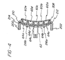
- Fig. 4 is a sectional view taken along the lines and arrows 4-4 shown in Fig. 3.
- Turning to Fig. 1, this view shows the overall organization of a typical photoconductive cylinder and associated mechanisms for formation of the latent electrostatic image, and subsequent image formation on the cylinder surface. A rotatable
photoconductive drum 50, typically As₂Se₃ or SeTe, rotates in a counterclockwise direction as indicated by the arrow shown oncylinder 50 in Fig. 1. Special systems are arranged sequentially arounddrum 50 as shown in Fig. 1, to accomplish the desired formation and transfer of images onto web w. These systems include a highintensity charging apparatus 52, exposing-discharging (or imaging)apparatus 54, developingapparatus 55,transfer apparatus 56 andcleaning apparatus 58. These assure that the drum surface is charged, exposed, discharged and cleared of residual toner, while the developed images are continually transferred to the web material w. -
Charging apparatus 52 comprises a plurality of corona discharge devices comprisingcorona discharge wires 60 disposed within appropriately shaped shieldedmembers 62 with eachwire 60 and associatedshield member 62 forming a separate focusing chamber 64. Although only two such corona discharge devices are shown in Fig. 1, in practice, five of same are employed (see Fig. 4) to help ensure that the proper potential is imparted to the photoconductive surface. It is to be appreciated that due to the rapid peripheral speed ofdrum 50, it is necessary to provide such a large array of corona charging means in light of the necessity of imparting a relatively high charge potential of the order specified to the photoconductive surface within the very short time provided for this task. - The charge imparted by the coronas to the photoconductive cylinder is in the order of at least +1000 volts d.c., preferably between +1000 and +1450 volts. At present, a charge of +1100 v is clearly preferred. In order to charge the photoconductive surface to such high voltages, it is necessary to charge each of the
corona charge wires 60 at +5600 to about +6500 v d.c. The corona assemblies extend across thedrum surface 51 and along an arc closely parallel tosurface 51. In a successful embodiment using a drum having a 33-inch circumference (thus 10.504-inch diameter) the arcuate length of the charging unit is about 4.5 inches or somewhat greater than 1/8 th of the drum circumference. - Proceeding counterclockwise around the drum (as viewed in Fig. 1), there is a charge potential sensor 65 (an electrometer) which senses the voltage at the
surface 55 and provides a continuous feedback signal to thecharging power supply 67 to thereby adjust the charge level of thephotoconductor surface 51 regardless of variations due, for example, to irregularities in the power supply or changes in the peripheral velocity ofdrum 50, drum shape irregularities or photoconductor wear and deterioration. - Turning to Fig. 2, the information sensed by
sensor 65 is forwarded to ahigh speed amplifier 102 which receives the signal fromsensor 65 and, as an output, forwards a voltage signal from 0-5 v to resistivecapacitance network 104 which averages fluctuations in the signal over a time period of about 2.5 seconds.Network 104 is of conventional nature and may be referred to as a time constant RC network. The output from the RC network is a smooth signal that is forwarded toprogrammable logic controller 106 that is, for example, Texas Instruments Model 565. - The signal received by the
PLC 106 is compared to an expected normal signal that corresponds to, for example, +1100 v charge on the photoconductor surface. When variations of either plus or minus 20% of this value are sensed by the PLC, a signal is sent to the variable voltagepower supply unit 67 to either increase or decrease potential output supplied to thecorona discharge wires -
Corona discharge wires 60a-e are each connected to resistors 108a-e prior to grounding of the wires. The resistors have resistances, each of about 3 megohms. The resistors are necessary in order to inhibit arcing that may otherwise occur due to the large potentials (i.e., +5600 v to +6800 v) impressed upon the wires in order to impart the correct voltages to the photoconductor. - Turning now to Figs. 3 and 4, there is shown the corona charging array and associated support mechanism.
Brackets frame members drum 50. That is, the brackets extend in the axial direction ofdrum 50. Theshield member 62 is generally arcuately shaped and is inserted intobrackets flanges corresponding recesses - The
shield member 62 is preferably formed of lightweight extruded aluminum with the brackets being composed of, for example, Delrin plastic. As shown, fivecorona discharge wires 60a-e are provided with each wire being disposed in and extending along a substantially "C" cross-sectioned channel 64a-e formed in theshield 62. The channels 64a-e are evenly spaced from each other and provide a separate housing for eachwire 60a-e to ensure that the ions created bydischarge wires 60a-e are properly deflected and directed onto the surface ofdrum 50 to provide for proper charging thereof. - End-
cap members shield 62 and are secured thereto by the provision ofscrews 216a-d. The end-cap members are preferably made of plastic and serve to house the electrical leads thus securing same, fuses, and resistors that are also connected to thewires 60a-e. - As is apparent from review of Figs. 3 and 4, the provision of
shield 62, the five evenly spaced channels thereof 64a-e, and the slidable mounting of the shield to thebrackets wires 60a-e and easy service and repair of the entire charging unit. - Once again considering Fig. 1, an
imaging device 54 is mounted to extend transversely of therotating drum surface 51. Light from the imaging device operates to discharge the background or non-image areas of the passing drum surface to a substantially lower potential, for example, in the order of +100 to +300 volts d.c. by exposing individual dot areas to radiation at a predetermined frequency, whereby the remaining or image areas comprise a latent electrostatic image of the printed portions of the form. - Although the use of a digitally driven L.E.D. arrangement is preferred for providing the requisite image, other conventional means for forming the requisite image may also be utilized. For instance, laser printing and conventional exposure methods through transparencies and the like may also be utilized, although they are not preferred.
- The latent electrostatic image then is carried, as the drum rotates, past developing
station 55 where it is subjected to the action of a liquid toner developer of the type comprising a dielectric carrier liquid material, such as the Isopar series of hydrocarbon fractions, resinous binder particles, and color-imparting dye and/or pigment particles. The desired charge may be chemically supplied to the resin-pigment/dye particles by utilization of well-known charge control agents such as lecithin and alkylated vinylpyrrolidone materials. In the embodiment shown,drum 50 comprises an As₂Se₃ photoconductive layer to which charge coronas 52 impart a positive charge. Toner particles are accordingly provided with a negative charge in the range of about 60 to 75 picamhos/cm. - Proceeding further in the counterclockwise direction with respect to Fig. 1, there is shown
transfer apparatus 56 as including a pair of idler rollers 90 which guide web W onto the "3 o'clock" location ofdrum 50, and behind the web path at this location is atransfer coratron 92. The web is driven at a speed equal to the velocity ofdrum surface 51, to minimize smudging or disturbance of the developed image on thesurface 51. Both toner particles and liquid carrier transfer to the web, including carrier liquid on thedrum surface 51 in the background areas. - Accordingly, by the imposition of a high d.c. electrical voltage by the
transfer coratron 92 onto the backside of travelling web W and since the charge on the image oncylinder 50 is lower, an electrical field between the web W to the cylinder is created. The negatively charged solids toner particles are thereby strongly directed to migrate counter to this field and adhere to the web surface in the web-cylinder interface area. - Although this invention has been described with respect to certain preferred embodiments, it will be appreciated that a wide variety of equivalents may be substituted for those specific elements shown and described herein, all without departing from the scope of the invention as defined in the appended claims.
Claims (16)
- High speed electrophotographic printing process of the type including a rotatable cylinder having a photoconductive surface rotating at a peripheral speed of at least about 100 ft./min., wherein a latent electrostatic image is formed on said surface by imparting a first charge of a desired given polarity and desired potential over said surface and subsequently exposing non-image areas of said surface to dissipate said first charge in said non-image areas to form a second charge in said non-image areas of lesser potential than and common polarity with said first charge, characterised by:
sensing the potential imparted by said first charge, and, in response to said sensing, adjusting the potential imparted by said first charge to correspond to said desired potential. - Process as recited in claim 1 wherein said sensing comprises providing an electrometer to scan the voltage imparted to said cylinder.
- Process as recited in claim 1 or 2 wherein said first charge is imparted to said photoconductive surface by an array of corona discharge means positioned transversely across said cylinder.
- Process as recited in claim 3 comprising charging said corona discharge means with a potential of about +5600 to +6800 v and imparting a first charge to said cylinder surface of about +1000 to +1450 v therewith.
- Process as recited in claim 2, or claim 2 in combination with claim 3 or 4, wherein said sensing further comprises sending a signal from said electrometer to a programmable logic controller and comparing said signal to a predetermined value.
- Process as recited in claim 5 wherein said predetermined value corresponds to about +1100 v for said first charge.
- Process as recited in claim 5 or 6 further comprising, subsequent to said comparing, sending a signal from said programmable logic controller to a variable voltage source connected to said corona discharge means.
- High speed electrophotoconductive printing apparatus of the type including a rotatable cylinder having a photoconductive surface rotating at a peripheral speed of at least about 100 ft./min. and wherein means are provided for forming, on said surface, a latent electrostatic image by imparting a first charge of a given polarity and potential over said surface and for subsequently exposing non-image areas of said cylinder surface to dissipate said first charge in said non-image areas of said surface to form, in said non-image areas, a second charge of lesser potential than and common polarity with said first charge, characterised by:a) sensor means located proximate said cylinder for sensing the potential imparted by said first charge; andb) adjustment means, responsive to said sensor means, for adjusting the potential actually imparted by said first charge to correspond to said desired potential.
- Apparatus as recited in claim 8 wherein said sensor means comprises an electrometer.
- Apparatus as recited in claim 8 or 9 further comprising an array of corona discharge means extending transversely across said rotatable cylinder and closely spaced therefrom for imparting said first charge.
- Apparatus as recited in claim 10 wherein said adjustment means comprises an adjustable power source connected to said array of corona discharge means.
- Apparatus as recited in claim 10 or 11 wherein each member of said array is connected to a resistor means.
- Apparatus as recited in claim 12 wherein each said resistor means has a resistance of about three megohms.
- Apparatus as recited in claim 10, or claim 10 in combination with any of claims 11, 12 or 13, wherein said electrometer is electrically connected to a high speed amplifier.
- Apparatus as recited in claim 14 wherein said high speed amplifier is electrically connected to a resistive capacitance network (RCN).
- Apparatus as recited in claim 15 wherein said RCN is connected to a programmable logic controller which is connected to said adjustable power source.
Applications Claiming Priority (2)
| Application Number | Priority Date | Filing Date | Title |
|---|---|---|---|
| US07/442,880 US5017964A (en) | 1989-11-29 | 1989-11-29 | Corona charge system and apparatus for electrophotographic printing press |
| US442880 | 1989-11-29 |
Publications (2)
| Publication Number | Publication Date |
|---|---|
| EP0430648A2 true EP0430648A2 (en) | 1991-06-05 |
| EP0430648A3 EP0430648A3 (en) | 1992-04-08 |
Family
ID=23758515
Family Applications (1)
| Application Number | Title | Priority Date | Filing Date |
|---|---|---|---|
| EP19900312882 Withdrawn EP0430648A3 (en) | 1989-11-29 | 1990-11-27 | Corona charge system and apparatus for electrophotographic printing press |
Country Status (3)
| Country | Link |
|---|---|
| US (1) | US5017964A (en) |
| EP (1) | EP0430648A3 (en) |
| CA (1) | CA2029813A1 (en) |
Families Citing this family (4)
| Publication number | Priority date | Publication date | Assignee | Title |
|---|---|---|---|---|
| JP3019355B2 (en) * | 1990-03-19 | 2000-03-13 | ミノルタ株式会社 | Image forming device |
| JPH04251859A (en) * | 1991-01-29 | 1992-09-08 | Murata Mach Ltd | Method for measuring electrostatic potential |
| CA2076791C (en) * | 1991-09-05 | 1999-02-23 | Mark A. Scheuer | Charged area (cad) image loss control in a tri-level imaging apparatus |
| US5526097A (en) * | 1995-06-07 | 1996-06-11 | Lexmark International, Inc. | Cartridge utilizing a plurality of contact charging members |
Citations (7)
| Publication number | Priority date | Publication date | Assignee | Title |
|---|---|---|---|---|
| US3900735A (en) * | 1971-09-10 | 1975-08-19 | Hoechst Ag | Corona discharge apparatus |
| US3934141A (en) * | 1974-07-03 | 1976-01-20 | Xerox Corporation | Apparatus for automatically regulating the amount of charge applied to an insulating surface |
| US3972305A (en) * | 1969-04-11 | 1976-08-03 | Xerox Corporation | Imaging system |
| EP0018897A1 (en) * | 1979-04-30 | 1980-11-12 | EASTMAN KODAK COMPANY (a New Jersey corporation) | Method and apparatus for corona charging a moving surface |
| DE3140853A1 (en) * | 1980-10-20 | 1982-06-16 | Minolta Camera K.K., Osaka | ELECTROPHOTOGRAPHIC COPIER |
| US4417804A (en) * | 1981-06-19 | 1983-11-29 | Xerox Corporation | High voltage comparator for photoreceptor voltage control |
| JPS59178467A (en) * | 1983-03-30 | 1984-10-09 | Fujitsu Ltd | Control device for surface potential of photosensitive body in electrostatic recorder |
Family Cites Families (53)
| Publication number | Priority date | Publication date | Assignee | Title |
|---|---|---|---|---|
| NL113142C (en) * | 1959-04-22 | 1900-01-01 | ||
| US3604925A (en) * | 1968-12-03 | 1971-09-14 | Zerox Corp | Apparatus for controlling the amount of charge applied to a surface |
| US3599070A (en) * | 1969-09-17 | 1971-08-10 | Siltron | Battery charger and emergency power supply for illumination device |
| CA939732A (en) * | 1969-11-11 | 1974-01-08 | Masayoshi Furuichi | Apparatus for supplementing toner in electrophotographic machines |
| US4021586A (en) * | 1970-10-08 | 1977-05-03 | Canon Kabushiki Kaisha | Method of and means for the development of electrostatic images |
| US3736103A (en) * | 1971-09-20 | 1973-05-29 | Tec Systems | Incinerator combustion apparatus |
| US3739491A (en) * | 1971-09-22 | 1973-06-19 | Tec Systems | High velocity air web dryer |
| US4019055A (en) * | 1972-04-19 | 1977-04-19 | Xerox Corporation | Corona cleaning assembly |
| US3788739A (en) * | 1972-06-21 | 1974-01-29 | Xerox Corp | Image compensation method and apparatus for electrophotographic devices |
| JPS5434541B2 (en) * | 1972-12-22 | 1979-10-27 | ||
| US3776440A (en) * | 1973-01-30 | 1973-12-04 | Tec Systems | Web handling apparatus |
| US3873013A (en) * | 1973-10-04 | 1975-03-25 | Tec Systems | High velocity web floating air bar having center exhaust means |
| JPS5188230A (en) * | 1975-01-31 | 1976-08-02 | ||
| US3964656A (en) * | 1975-04-14 | 1976-06-22 | Tec Systems, Inc. | Air bar assembly for web handling apparatus |
| US3961193A (en) * | 1975-05-27 | 1976-06-01 | Xerox Corporation | Self adjusting corona device |
| US4177730A (en) * | 1976-11-04 | 1979-12-11 | Harris Corporation | Method and apparatus for web printing |
| US4116620A (en) * | 1977-05-23 | 1978-09-26 | Tec Systems, Inc. | Web drying apparatus having means for heating recirculated air |
| JPS54628A (en) * | 1977-06-03 | 1979-01-06 | Ricoh Co Ltd | Multiple copying method for electronic copying apparatus |
| US4295383A (en) * | 1977-11-11 | 1981-10-20 | W. R. Grace & Co. | Variable speed drive |
| US4455562A (en) * | 1981-08-14 | 1984-06-19 | Pitney Bowes Inc. | Control of a light emitting diode array |
| US4182472A (en) * | 1978-07-13 | 1980-01-08 | W. R. Grace & Co. | Contactless turning guide for running webs |
| US4197972A (en) * | 1978-08-28 | 1980-04-15 | W. R. Grace & Co. | Contactless turning guide having air slots longitudinally along running web edges |
| US4197973A (en) * | 1978-10-12 | 1980-04-15 | W. R. Grace & Co. | High velocity web floating air bar having air flow straightening means for air discharge slot means |
| US4201323A (en) * | 1978-10-12 | 1980-05-06 | W. R. Grace & Co. | High velocity web floating air bar having a recessed Coanda plate |
| US4197971A (en) * | 1978-10-12 | 1980-04-15 | W. R. Grace & Co. | High velocity web floating air bar having an internal passage for transverse air discharge slot means |
| US4286039A (en) * | 1979-05-15 | 1981-08-25 | Savin Corporation | Method and apparatus for removing excess developing liquid from photoconductive surfaces |
| US4310238A (en) * | 1979-09-08 | 1982-01-12 | Ricoh Company, Ltd. | Electrostatic copying apparatus |
| US4325627A (en) * | 1979-12-19 | 1982-04-20 | Savin Corporation | Method and apparatus for liquid-developing latent electrostatic images |
| US4265384A (en) * | 1980-01-21 | 1981-05-05 | W. R. Grace & Co. | Air bar having asymmetrical inlet |
| US4288015A (en) * | 1980-02-11 | 1981-09-08 | W. R. Grace & Co. | Contactless web turning guide |
| US4282998A (en) * | 1980-05-09 | 1981-08-11 | W. R. Grace & Co. | Maintenance of constant web clearance at contactless turning guide |
| US4343769A (en) * | 1980-08-11 | 1982-08-10 | W. R. Grace & Co. | Catalytic solvent vapor incinerating apparatus |
| US4369584A (en) * | 1981-04-16 | 1983-01-25 | W. R. Grace & Co. | Preventing air film between web and roller |
| US4469428A (en) * | 1981-08-08 | 1984-09-04 | Mita Industrial Co., Ltd. | Corona discharging apparatus used in an electrostatic photographic copying machine |
| US4462169A (en) * | 1982-02-19 | 1984-07-31 | W. R. Grace & Company | Web dryer solvent vapor control means |
| US4425719A (en) * | 1982-03-15 | 1984-01-17 | W. R. Grace & Co. | Compact air bar assembly for contactless web support |
| US4399203A (en) * | 1982-04-15 | 1983-08-16 | The Standard Oil Company | Sulfide and selenide compositions |
| US4480859A (en) * | 1982-06-28 | 1984-11-06 | W. R. Grace & Co. | Flexible connector for flat wall ducting |
| US4564282A (en) * | 1982-11-15 | 1986-01-14 | Xerox Corporation | Corona charging device |
| US4474496A (en) * | 1983-01-24 | 1984-10-02 | W. R. Grace & Co. | Compact dryer for two web stretches |
| US4482624A (en) * | 1983-02-15 | 1984-11-13 | The Mead Corporation | Photosensitive material employing encapsulated radiation sensitive composition and process for improving sensitivity by sequestering oxygen |
| US4515292A (en) * | 1983-05-19 | 1985-05-07 | Burroughs Corporation | Digital implementation of toner concentration sensing apparatus |
| JPS6032074A (en) * | 1983-08-03 | 1985-02-19 | Hitachi Metals Ltd | Developing device |
| JPS6147973A (en) * | 1984-08-16 | 1986-03-08 | Ricoh Co Ltd | Toner concentration controlling method |
| US4563086A (en) * | 1984-10-22 | 1986-01-07 | Xerox Corporation | Copy quality monitoring for magnetic images |
| US4860924A (en) * | 1986-02-14 | 1989-08-29 | Savin Corporation | Liquid developer charge director control |
| US4631244A (en) * | 1986-02-18 | 1986-12-23 | E. I. Du Pont De Nemours And Company | Process for preparation of liquid toners for electrostatic imaging using polar additive |
| US4848633A (en) * | 1986-02-28 | 1989-07-18 | Thermo Electron Web Systems, Inc. | Non-contact web turning and drying apparatus |
| US4702985A (en) * | 1986-04-28 | 1987-10-27 | E. I. Du Pont De Nemours And Company | Aminoalcohols as adjuvant for liquid electrostatic developers |
| US4827315A (en) * | 1986-12-16 | 1989-05-02 | Larry Wolfberg | Printing press |
| US4760423A (en) * | 1987-03-12 | 1988-07-26 | Savin Corporation | Apparatus and method for reducing hydrocarbon emissions from a liquid-based electrophotographic copying machine |
| US4829336A (en) * | 1988-04-18 | 1989-05-09 | International Business Machines Corporation | Toner concentration control method and apparatus |
| US4828956A (en) * | 1988-05-02 | 1989-05-09 | Xerox Corporation | Processes for maintaining the triboelectric stability of electrophotographic developers |
-
1989
- 1989-11-29 US US07/442,880 patent/US5017964A/en not_active Expired - Fee Related
-
1990
- 1990-11-13 CA CA002029813A patent/CA2029813A1/en not_active Abandoned
- 1990-11-27 EP EP19900312882 patent/EP0430648A3/en not_active Withdrawn
Patent Citations (7)
| Publication number | Priority date | Publication date | Assignee | Title |
|---|---|---|---|---|
| US3972305A (en) * | 1969-04-11 | 1976-08-03 | Xerox Corporation | Imaging system |
| US3900735A (en) * | 1971-09-10 | 1975-08-19 | Hoechst Ag | Corona discharge apparatus |
| US3934141A (en) * | 1974-07-03 | 1976-01-20 | Xerox Corporation | Apparatus for automatically regulating the amount of charge applied to an insulating surface |
| EP0018897A1 (en) * | 1979-04-30 | 1980-11-12 | EASTMAN KODAK COMPANY (a New Jersey corporation) | Method and apparatus for corona charging a moving surface |
| DE3140853A1 (en) * | 1980-10-20 | 1982-06-16 | Minolta Camera K.K., Osaka | ELECTROPHOTOGRAPHIC COPIER |
| US4417804A (en) * | 1981-06-19 | 1983-11-29 | Xerox Corporation | High voltage comparator for photoreceptor voltage control |
| JPS59178467A (en) * | 1983-03-30 | 1984-10-09 | Fujitsu Ltd | Control device for surface potential of photosensitive body in electrostatic recorder |
Non-Patent Citations (1)
| Title |
|---|
| PATENT ABSTRACTS OF JAPAN vol. 9, no. 37 (P-335)(1760) 16 February 1985 & JP-A-59 178 467 ( FUJITSU K.K. ) 9 October 1984 * |
Also Published As
| Publication number | Publication date |
|---|---|
| US5017964A (en) | 1991-05-21 |
| EP0430648A3 (en) | 1992-04-08 |
| CA2029813A1 (en) | 1991-05-30 |
Similar Documents
| Publication | Publication Date | Title |
|---|---|---|
| US5164779A (en) | Image forming apparatus with dual voltage supplies for selectively charging and discharging an image bearing member | |
| EP0555102B1 (en) | Image forming apparatus having charging member contactable to image bearing member | |
| US4432634A (en) | Electrophotographic copying apparatus | |
| US5243383A (en) | Image forming apparatus with predictive electrostatic process control system | |
| KR0168868B1 (en) | Image transfer device for an image forming apparatus | |
| US5926669A (en) | Image forming apparatus and method of forming an image with enhanced transfer condition settings | |
| CA1066354A (en) | Corona generator for multicolor electrocopier | |
| US5300984A (en) | Image forming apparatus having controlled transfer unit | |
| US4003650A (en) | Controller for reproduction apparatus | |
| US3805069A (en) | Regulated corona generator | |
| US3891316A (en) | Multi-process control system for an electrophotographic printing machine | |
| EP0430648A2 (en) | Corona charge system and apparatus for electrophotographic printing press | |
| US20060165438A1 (en) | Image forming apparatus | |
| EP0531063B1 (en) | Charged area image loss control in a tri-level imaging apparatus | |
| KR100608053B1 (en) | Dischage system and method for photographic image forming apparatus | |
| US20090052915A1 (en) | Constant voltage leveling device for integrated charging system | |
| US5826138A (en) | Toner supply roller applied with a.c. voltage in nonmagnetic single component developing device | |
| US5008707A (en) | Simultaneous charging and exposure for pictorial quality | |
| JP2003131444A (en) | Image forming apparatus | |
| US3822093A (en) | Transfer regulating apparatus | |
| US5457519A (en) | Two dimensional process control system for an electrostratographic printing machine | |
| JPH0239183A (en) | Image forming device | |
| US5881347A (en) | Biasing method and apparatus for electrostatically transferring an image | |
| US3909126A (en) | Multi-process control system for an electrophotographic printing machine | |
| JP3222448B2 (en) | Color image recording device |
Legal Events
| Date | Code | Title | Description |
|---|---|---|---|
| PUAI | Public reference made under article 153(3) epc to a published international application that has entered the european phase |
Free format text: ORIGINAL CODE: 0009012 |
|
| 17P | Request for examination filed |
Effective date: 19901208 |
|
| AK | Designated contracting states |
Kind code of ref document: A2 Designated state(s): BE CH DE ES FR GB IT LI LU NL SE |
|
| PUAL | Search report despatched |
Free format text: ORIGINAL CODE: 0009013 |
|
| AK | Designated contracting states |
Kind code of ref document: A3 Designated state(s): BE CH DE ES FR GB IT LI LU NL SE |
|
| 17Q | First examination report despatched |
Effective date: 19930709 |
|
| STAA | Information on the status of an ep patent application or granted ep patent |
Free format text: STATUS: THE APPLICATION IS DEEMED TO BE WITHDRAWN |
|
| 18D | Application deemed to be withdrawn |
Effective date: 19931120 |