EP0433752A1 - Inductive coupler for transfer of electric energy - Google Patents
Inductive coupler for transfer of electric energy Download PDFInfo
- Publication number
- EP0433752A1 EP0433752A1 EP90123189A EP90123189A EP0433752A1 EP 0433752 A1 EP0433752 A1 EP 0433752A1 EP 90123189 A EP90123189 A EP 90123189A EP 90123189 A EP90123189 A EP 90123189A EP 0433752 A1 EP0433752 A1 EP 0433752A1
- Authority
- EP
- European Patent Office
- Prior art keywords
- coupler
- magnetic circuit
- air gap
- electric energy
- primary
- Prior art date
- Legal status (The legal status is an assumption and is not a legal conclusion. Google has not performed a legal analysis and makes no representation as to the accuracy of the status listed.)
- Withdrawn
Links
- 230000001939 inductive effect Effects 0.000 title claims abstract description 8
- 230000005291 magnetic effect Effects 0.000 claims abstract description 25
- 239000003990 capacitor Substances 0.000 claims abstract description 5
- 229910000859 α-Fe Inorganic materials 0.000 claims description 6
- 230000005294 ferromagnetic effect Effects 0.000 claims description 3
- 230000000694 effects Effects 0.000 claims 1
- 239000000306 component Substances 0.000 description 3
- 238000010276 construction Methods 0.000 description 3
- 230000001419 dependent effect Effects 0.000 description 3
- 238000005516 engineering process Methods 0.000 description 3
- XEEYBQQBJWHFJM-UHFFFAOYSA-N Iron Chemical group [Fe] XEEYBQQBJWHFJM-UHFFFAOYSA-N 0.000 description 2
- 239000003795 chemical substances by application Substances 0.000 description 2
- 239000003302 ferromagnetic material Substances 0.000 description 2
- 239000002131 composite material Substances 0.000 description 1
- 239000008358 core component Substances 0.000 description 1
- 230000008878 coupling Effects 0.000 description 1
- 238000010168 coupling process Methods 0.000 description 1
- 238000005859 coupling reaction Methods 0.000 description 1
- 239000000696 magnetic material Substances 0.000 description 1
- 239000000843 powder Substances 0.000 description 1
- 238000009738 saturating Methods 0.000 description 1
- 239000013535 sea water Substances 0.000 description 1
Images
Classifications
-
- H—ELECTRICITY
- H01—ELECTRIC ELEMENTS
- H01F—MAGNETS; INDUCTANCES; TRANSFORMERS; SELECTION OF MATERIALS FOR THEIR MAGNETIC PROPERTIES
- H01F38/00—Adaptations of transformers or inductances for specific applications or functions
- H01F38/14—Inductive couplings
Definitions
- the invention relates to an inductive coupler for transfer of electric energy.
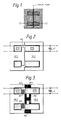
- Usual inductive couplers are constructed so that the coupler is simply a transformer, the iron core of which is parted when the primary and secondary part of the coupler are disconnected ( Figure 1).
- This kind of coupler has many disadvantages. It has a high short-circuit reactance, because the primary and secondary coils are at a distance from one another. Owing to the high short-circuit reactance the secondary voltage of the coupler is liable to be dependent on the load. In addition, the secondary voltage of the coupler is almost directly proportional to the primary voltage, so that the secondary voltage is liable to be dependent on the primary voltage. This is one reason for difficulties in cases where the primary voltage has to be supplied by a long sea cable, where the occuring voltage variations appear as such in the primary voltage of the coupler. In addition, the primary and secondary part of the coupler cannot be parted if the coupler is energised, because the primary current, when the magnetic circuit formed by the iron core is disconnected, can grow so strong that the primary coil will be destroyed.
- GB patent specification No. 2020116A and US patent specification No. 4558271 disclose inductive couplers in which ferroresonant principle is used. However, they suffer from the disadvantage of the mechanically and electrically complicated construction, one result being that the coupler must be bigger and the alignment has to be precise.
- the device according to the invention is characterized in what is stated in characteristics of claim 1.
- Important advantages of the invention are the good stability of voltage both with respect to the load changes and to variations of the primary voltages, the possibility to disconnect the coupler mechanically even if it is energised, good efficiency and small tolerance requirements when connecting the primary part and the secondary part mechanically.
- the stability of voltage is of special importance in cases where several couplers are to be connected in series or if the coupler operates at the end of a long cable where the cable causes a change in the primary voltage of the coupler, dependent on the load .
- the device according to the invention is based on principle of the ferroresonant transformer, known as such.
- a ferroresonant transformer comprises typically a reactance with a standard air gap and a capacitor in the secondary part which will be excited to a resonance corresponding to the power frequency.
- a good stability of voltage both with respect to the load changes and to variations of the primary voltages can be achieved with the ferroresonant principle.
- the stability of voltage with respect to the load is good by the ferroresonant principle, although the primary and secondary coils are situated in different parts of the coupler, is a special advantage. In addition to the stability of voltage, also a good power efficiency can be achieved.
- the air gap of the ferroresonant transformer (AG in figure 2) is placed in the primary part of the coupler firstly in a way that the primary part forms a pure linear choke when it operates mechanically disconnected from the secondary part.
- the air gap is preferably dimensioned the primary current can be restricted to a safe value even if the primary part operates mechanically disconnected from the secondary part, but energised.
- the air gap of the primary part is placed in the primary part so that the magnetic circuit of the secondary part MC2 is simply magnetically coupled between the poles of this air gap, whereby a magnetic circuit typical of the ferroresonant transformer is built up (figure 2).
- the secondary magnetic circuit MC2 induces secondary voltage to the secondary coil C2, said secondary voltage supplying the secondary resonance capacitor C and the eventual load.
- the secondary magnetic circuit is, in one way or another, provided with a part or parts, by the magnetic saturation of which the secondary voltage increased by the resonance, is limited to the desired value.
- Figure 3 illustrates as an example a solution with PM-ferrite core components according to DIN 41989.
- the air gap AG of the primary part can be realized by a simple (f.ex. diskshaped) extra part M1 made of some ferromagnetic material.
- the required saturation in the magnetic circuit of the secondary part can also be realized by a simple extra part M2 made of some ferromagnetic material (f.ex. ferromagnetic powder composite).
- the magnetic material of this kind of a saturating extra part has to be such as to have a sufficienty stable saturation density with respect to the temperature. It is necessary to realize the saturation with this kind of an extra part especially in cases where the secondary magnetic circuit includes ferrite.
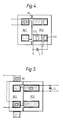
- FIG 4 illustrates an embodiment, where the secondary coil comprises two parts C21 and C22 connected in series. The secondary voltage is taken from part C21 and the resonance capacitor C is connected between the end poles of the coil.
- FIG 5 illustrates an embodiment, where the primary coil is devided into two parts C11 and C12 connected in series and placed in the end poles of the primary magnetic circuit of the coupler.
Abstract
Inductive coupler for transfer of electric energy. The coupler comprises the first part for receiving electric energy, said part comprising a magnetic circuit (MC1) with a standard air gap (AG) and a primary coil (C1) that magnetizes said circuit, and the other part for giving off electric energy, comprising a magnetic circuit (MC2) saturable by nominal use. A secondary coil (C2) is inductively coupled with said magnetic circuit and a capacitor (C) coupled with said secondary coil to produce resonance. The magnetic circuit (MG2) of the other part closes the air gap (AG) of the first part magnetically when the first part and the other part of the coupler are mechanically connected with one another.
Description
- The invention relates to an inductive coupler for transfer of electric energy.
- It is possible to use f.ex. for the electric energy supply of electric appliances used in subsea technology inductive couplers through which the energy is transferred without disconnectable galvanic couplings. This is one way to achieve constructions that operate reliably under those exacting conditions effected f.ex. by sea water.
- Usual inductive couplers are constructed so that the coupler is simply a transformer, the iron core of which is parted when the primary and secondary part of the coupler are disconnected (Figure 1). This kind of coupler has many disadvantages. It has a high short-circuit reactance, because the primary and secondary coils are at a distance from one another. Owing to the high short-circuit reactance the secondary voltage of the coupler is liable to be dependent on the load. In addition, the secondary voltage of the coupler is almost directly proportional to the primary voltage, so that the secondary voltage is liable to be dependent on the primary voltage. This is one reason for difficulties in cases where the primary voltage has to be supplied by a long sea cable, where the occuring voltage variations appear as such in the primary voltage of the coupler. In addition, the primary and secondary part of the coupler cannot be parted if the coupler is energised, because the primary current, when the magnetic circuit formed by the iron core is disconnected, can grow so strong that the primary coil will be destroyed.
- GB patent specification No. 2020116A and US patent specification No. 4558271 disclose inductive couplers in which ferroresonant principle is used. However, they suffer from the disadvantage of the mechanically and electrically complicated construction, one result being that the coupler must be bigger and the alignment has to be precise.
- With help of the device according to the invention the aforementioned disadvantages can be helped. To achieve the improvements, the device according to the invention is characterized in what is stated in characteristics of claim 1.
- Important advantages of the invention are the good stability of voltage both with respect to the load changes and to variations of the primary voltages, the possibility to disconnect the coupler mechanically even if it is energised, good efficiency and small tolerance requirements when connecting the primary part and the secondary part mechanically. The stability of voltage is of special importance in cases where several couplers are to be connected in series or if the coupler operates at the end of a long cable where the cable causes a change in the primary voltage of the coupler, dependent on the load .
- In the following the invention will be described in more detail with reference to the accompanying drawing, in which
- Figure 1 illustrates a conventional inductive coupler,
- Figure 2 illustrates essential characteristics of the coupler according to the invention,
- Figure 3 illustrates one embodiment of the coupler according to the invention where commercially available standardized magnetic components have been used,
- Figure 4 illustrates an example of one alternative embodiment within the scope of the claims,
- Figure 5 illustrates another example of one alternative embodiment within the scope of the claims.
- The device according to the invention is based on principle of the ferroresonant transformer, known as such. A ferroresonant transformer comprises typically a reactance with a standard air gap and a capacitor in the secondary part which will be excited to a resonance corresponding to the power frequency. A good stability of voltage both with respect to the load changes and to variations of the primary voltages can be achieved with the ferroresonant principle. On the basis of the aforementioned, especially the fact, that the stability of voltage with respect to the load is good by the ferroresonant principle, although the primary and secondary coils are situated in different parts of the coupler, is a special advantage. In addition to the stability of voltage, also a good power efficiency can be achieved.
- In the device according to the invention the air gap of the ferroresonant transformer (AG in figure 2) is placed in the primary part of the coupler firstly in a way that the primary part forms a pure linear choke when it operates mechanically disconnected from the secondary part. When the air gap is preferably dimensioned the primary current can be restricted to a safe value even if the primary part operates mechanically disconnected from the secondary part, but energised.
- Secondly, the air gap of the primary part is placed in the primary part so that the magnetic circuit of the secondary part MC2 is simply magnetically coupled between the poles of this air gap, whereby a magnetic circuit typical of the ferroresonant transformer is built up (figure 2). The secondary magnetic circuit MC2 induces secondary voltage to the secondary coil C2, said secondary voltage supplying the secondary resonance capacitor C and the eventual load. The secondary magnetic circuit is, in one way or another, provided with a part or parts, by the magnetic saturation of which the secondary voltage increased by the resonance, is limited to the desired value.
- The aforementioned solutions of construction make it possible to use, in practical applications, for magnetic circuits of both the primary and the secondary part existing commercial and standardized magnetic components, f.ex. ferrites. Figure 3 illustrates as an example a solution with PM-ferrite core components according to DIN 41989. When using said components the air gap AG of the primary part can be realized by a simple (f.ex. diskshaped) extra part M1 made of some ferromagnetic material. The required saturation in the magnetic circuit of the secondary part can also be realized by a simple extra part M2 made of some ferromagnetic material (f.ex. ferromagnetic powder composite). The magnetic material of this kind of a saturating extra part has to be such as to have a sufficienty stable saturation density with respect to the temperature. It is necessary to realize the saturation with this kind of an extra part especially in cases where the secondary magnetic circuit includes ferrite.
- The meaning of the invention is detailed above with respect to applications of subsea technology. The intention, however, is in no way to limit the invention only to the subsea technology. I.a. in scope of the modern mechatronics it is easy to find targets where the device according to the invention can be applied to.
- Only one embodiment and disposition of the primary and secondary coils is disclosed above. An expert can alter disposition and number of coils in many ways within the scope of the claims. As an example figure 4 illustrates an embodiment, where the secondary coil comprises two parts C21 and C22 connected in series. The secondary voltage is taken from part C21 and the resonance capacitor C is connected between the end poles of the coil. Another example is the solution illustrated in figure 5, where the primary coil is devided into two parts C11 and C12 connected in series and placed in the end poles of the primary magnetic circuit of the coupler.
Claims (5)
- An inductive coupler for transfer of electric energy, consisting of the first part for receiving electric energy, said part comprising a magnetic circuit (MC1) with a standard air gap (AG) and a primary coil (C1) that magnetizes said circuit, and the other part for giving off electric energy, comprising a magnetic circuit (MC2) saturable by nominal use, a secondary coil (C2) inductively coupled with said magnetic circuit and a capacitor (C) coupled with said secondary coil to produce resonance, characterized in that the magnetic circuit (MC2) of the other part magnetically closes the air gap (AG) of the first part when the first part and the other part of the coupler are mechanically connected with one another.
- Coupler as claimed in claim 1, characterized in that the magnetic circuit (MC1) of its first part is composed of a ferrite core and a ferromagnetic spacing piece (M1) used for adjusting the air gap, and that the magnetic circuit (MC2) of its other part is composed of a ferrite core and ferromagnetic pieces (M2, M3, M4) magnetically connected in series with said ferrite core, said pieces being dimensioned so as to achieve a desired saturation of the magnetic circuit of the other part.
- Coupler as claimed in claim 1, characterized in that the air gap (AG) of the magnetic circuit (MC1) of its first part is dimensioned to a value that limits the current of the primary coil coupled with the power source that supplies the primary, to a safe value, even if the first and the other part of the coupler are mechanically disconnected from one another.
- Coupler as claimed in claim 1, characterized in that the first part includes only one coil.
- Coupler as claimed in claim 1, characterized in that the magnetic circuit (MC2) of the other part closes magnetically the air gap (AG) of the first part so that the inductance required by the ferroresonant effect is produced when the firt part and the other part of the coupler are mechanically connected with one another.
Applications Claiming Priority (2)
| Application Number | Priority Date | Filing Date | Title |
|---|---|---|---|
| FI896056A FI896056A (en) | 1989-12-18 | 1989-12-18 | INDUKTIV ANSLUTNING FOER OEVERFOERING AV ELENERGI. |
| FI896056 | 1989-12-18 |
Publications (1)
| Publication Number | Publication Date |
|---|---|
| EP0433752A1 true EP0433752A1 (en) | 1991-06-26 |
Family
ID=8529530
Family Applications (1)
| Application Number | Title | Priority Date | Filing Date |
|---|---|---|---|
| EP90123189A Withdrawn EP0433752A1 (en) | 1989-12-18 | 1990-12-04 | Inductive coupler for transfer of electric energy |
Country Status (3)
| Country | Link |
|---|---|
| EP (1) | EP0433752A1 (en) |
| FI (1) | FI896056A (en) |
| NO (1) | NO905429L (en) |
Cited By (8)
| Publication number | Priority date | Publication date | Assignee | Title |
|---|---|---|---|---|
| EP0552738A1 (en) * | 1992-01-22 | 1993-07-28 | Hughes Aircraft Company | Separable inductive coupler |
| EP0552736A1 (en) * | 1992-01-22 | 1993-07-28 | Hughes Aircraft Company | Wall/ceiling mounted inductive charger |
| US6711385B1 (en) * | 2000-07-06 | 2004-03-23 | Satius, Inc. | Coupler for wireless communications |
| US6825620B2 (en) * | 1999-06-21 | 2004-11-30 | Access Business Group International Llc | Inductively coupled ballast circuit |
| DE102004055154B4 (en) * | 2003-12-23 | 2007-10-18 | Sew-Eurodrive Gmbh & Co. Kg | Method for operating a system for contactless energy transmission, system for contactless energy transmission and transmitter head |
| US8198752B2 (en) | 2010-05-12 | 2012-06-12 | General Electric Company | Electrical coupling apparatus and method |
| US8441153B2 (en) | 2010-06-22 | 2013-05-14 | General Electric Company | Contactless power transfer system |
| US9697951B2 (en) | 2012-08-29 | 2017-07-04 | General Electric Company | Contactless power transfer system |
Citations (3)
| Publication number | Priority date | Publication date | Assignee | Title |
|---|---|---|---|---|
| US2379664A (en) * | 1942-08-29 | 1945-07-03 | Rca Corp | Electrical connector for loudspeakers and the like |
| FR2424617A1 (en) * | 1978-04-28 | 1979-11-23 | Elliott Brothers London Ltd | INDUCTIVE COUPLERS |
| GB2136635A (en) * | 1983-03-11 | 1984-09-19 | Marconi Avionics | Current-limited inductive coupler |
-
1989
- 1989-12-18 FI FI896056A patent/FI896056A/en not_active IP Right Cessation
-
1990
- 1990-12-04 EP EP90123189A patent/EP0433752A1/en not_active Withdrawn
- 1990-12-17 NO NO90905429A patent/NO905429L/en unknown
Patent Citations (3)
| Publication number | Priority date | Publication date | Assignee | Title |
|---|---|---|---|---|
| US2379664A (en) * | 1942-08-29 | 1945-07-03 | Rca Corp | Electrical connector for loudspeakers and the like |
| FR2424617A1 (en) * | 1978-04-28 | 1979-11-23 | Elliott Brothers London Ltd | INDUCTIVE COUPLERS |
| GB2136635A (en) * | 1983-03-11 | 1984-09-19 | Marconi Avionics | Current-limited inductive coupler |
Cited By (8)
| Publication number | Priority date | Publication date | Assignee | Title |
|---|---|---|---|---|
| EP0552738A1 (en) * | 1992-01-22 | 1993-07-28 | Hughes Aircraft Company | Separable inductive coupler |
| EP0552736A1 (en) * | 1992-01-22 | 1993-07-28 | Hughes Aircraft Company | Wall/ceiling mounted inductive charger |
| US6825620B2 (en) * | 1999-06-21 | 2004-11-30 | Access Business Group International Llc | Inductively coupled ballast circuit |
| US6711385B1 (en) * | 2000-07-06 | 2004-03-23 | Satius, Inc. | Coupler for wireless communications |
| DE102004055154B4 (en) * | 2003-12-23 | 2007-10-18 | Sew-Eurodrive Gmbh & Co. Kg | Method for operating a system for contactless energy transmission, system for contactless energy transmission and transmitter head |
| US8198752B2 (en) | 2010-05-12 | 2012-06-12 | General Electric Company | Electrical coupling apparatus and method |
| US8441153B2 (en) | 2010-06-22 | 2013-05-14 | General Electric Company | Contactless power transfer system |
| US9697951B2 (en) | 2012-08-29 | 2017-07-04 | General Electric Company | Contactless power transfer system |
Also Published As
| Publication number | Publication date |
|---|---|
| FI896056A0 (en) | 1989-12-18 |
| NO905429D0 (en) | 1990-12-17 |
| FI896056A (en) | 1991-06-19 |
| NO905429L (en) | 1991-06-19 |
Similar Documents
| Publication | Publication Date | Title |
|---|---|---|
| US3995209A (en) | Inductive connectors | |
| CA2218919C (en) | Power supply unit | |
| US4303902A (en) | Inductive coupler | |
| KR960015614A (en) | Electron Tuning Matching Network Using Adjustable Inductance Elements | |
| US5748013A (en) | Combined magnetic core | |
| WO2003094364A3 (en) | High current inductive coupler and current transformer for power lines | |
| ATE213869T1 (en) | LOW INDUCTIVE, LARGE AREA COIL FOR AN INDUCTIVELY COUPLED PLASMA SOURCE | |
| EP0557378A1 (en) | A power supply circuit with integrated magnetic components. | |
| EP1003295A3 (en) | Non-saturating, flux cancelling diplex filter for power line communications | |
| GR3006842T3 (en) | ||
| EP0433752A1 (en) | Inductive coupler for transfer of electric energy | |
| GB747736A (en) | Improvements in or relating to devices comprising a circuit of highly-permeable material and a permanent magnet for producing a pre-magnetizing field in said circuit | |
| US4943763A (en) | Ferroresonant transformer with dual outputs | |
| US4321652A (en) | Low voltage transformer relay | |
| US5450052A (en) | Magnetically variable inductor for high power audio and radio frequency applications | |
| US20020039061A1 (en) | Magnetically biased inductor or flyback transformer | |
| EP0484074A2 (en) | High-frequency, high-leakage-reactance transformer | |
| CN113223796A (en) | Magnetic material composition and magnetic element device | |
| US2059393A (en) | Magnetic core for high frequency inductances | |
| US6490180B2 (en) | Arrangement for transferring a control signal in a transformer | |
| GB852397A (en) | Improvements in or relating to matrix memory systems | |
| JPH10208949A (en) | Inverter transformer | |
| US3227921A (en) | Circuit for fluorescent discharge lamp including saturable reactors | |
| SU726595A1 (en) | Adjustable transformer | |
| CN213303855U (en) | Low-loss ferrite magnetic core |
Legal Events
| Date | Code | Title | Description |
|---|---|---|---|
| PUAI | Public reference made under article 153(3) epc to a published international application that has entered the european phase |
Free format text: ORIGINAL CODE: 0009012 |
|
| AK | Designated contracting states |
Kind code of ref document: A1 Designated state(s): DE DK FR GB IT SE |
|
| 17P | Request for examination filed |
Effective date: 19911121 |
|
| 17Q | First examination report despatched |
Effective date: 19920224 |
|
| STAA | Information on the status of an ep patent application or granted ep patent |
Free format text: STATUS: THE APPLICATION IS DEEMED TO BE WITHDRAWN |
|
| 18D | Application deemed to be withdrawn |
Effective date: 19920704 |