EP0434414B1 - IC carrier - Google Patents
IC carrier Download PDFInfo
- Publication number
- EP0434414B1 EP0434414B1 EP90313963A EP90313963A EP0434414B1 EP 0434414 B1 EP0434414 B1 EP 0434414B1 EP 90313963 A EP90313963 A EP 90313963A EP 90313963 A EP90313963 A EP 90313963A EP 0434414 B1 EP0434414 B1 EP 0434414B1
- Authority
- EP
- European Patent Office
- Prior art keywords
- portions
- shafts
- cover
- shaft
- recess
- Prior art date
- Legal status (The legal status is an assumption and is not a legal conclusion. Google has not performed a legal analysis and makes no representation as to the accuracy of the status listed.)
- Expired - Lifetime
Links
Images


Classifications
-
- H—ELECTRICITY
- H01—ELECTRIC ELEMENTS
- H01L—SEMICONDUCTOR DEVICES NOT COVERED BY CLASS H10
- H01L21/00—Processes or apparatus adapted for the manufacture or treatment of semiconductor or solid state devices or of parts thereof
- H01L21/67—Apparatus specially adapted for handling semiconductor or electric solid state devices during manufacture or treatment thereof; Apparatus specially adapted for handling wafers during manufacture or treatment of semiconductor or electric solid state devices or components ; Apparatus not specifically provided for elsewhere
- H01L21/673—Apparatus specially adapted for handling semiconductor or electric solid state devices during manufacture or treatment thereof; Apparatus specially adapted for handling wafers during manufacture or treatment of semiconductor or electric solid state devices or components ; Apparatus not specifically provided for elsewhere using specially adapted carriers or holders; Fixing the workpieces on such carriers or holders
- H01L21/6735—Closed carriers
- H01L21/67356—Closed carriers specially adapted for containing chips, dies or ICs
-
- H—ELECTRICITY
- H05—ELECTRIC TECHNIQUES NOT OTHERWISE PROVIDED FOR
- H05K—PRINTED CIRCUITS; CASINGS OR CONSTRUCTIONAL DETAILS OF ELECTRIC APPARATUS; MANUFACTURE OF ASSEMBLAGES OF ELECTRICAL COMPONENTS
- H05K7/00—Constructional details common to different types of electric apparatus
- H05K7/02—Arrangements of circuit components or wiring on supporting structure
- H05K7/10—Plug-in assemblages of components, e.g. IC sockets
- H05K7/1053—Plug-in assemblages of components, e.g. IC sockets having interior leads
- H05K7/1061—Plug-in assemblages of components, e.g. IC sockets having interior leads co-operating by abutting
- H05K7/1069—Plug-in assemblages of components, e.g. IC sockets having interior leads co-operating by abutting with spring contact pieces
Description
- This invention relates to an IC carrier comprising a base and a cover pivotably attached to the base.
- An IC carrier disclosed in USP4007479 comprises a base, and a cover pivotably connected to the base through an integrally molded hinge. The cover is not removably attached to the base.
- IC carriers disclosed in Japanese Utility Model Early laid-open Publication No. Sho 60-146089 and Japanese Utility Model Publication No. Sho 60-10310 are designed such that a canceled state of the shaft coupling is formed in a position where a cover is attached to a base.
- The latter, for example, has such a construction as that the shaft coupling is naturally canceled in a pivotal position where the pivot shaft is fitted to a cut-out portion of a key-groove.
- One of the above-mentioned conventional IC carriers has such a shortcoming as that the cover cannot be attached to and removed from the base, while the other has the advantage that the cover can be removably attached to the base but it has such a shortcoming as that the shaft coupling is naturally canceled in the position where the cover is attached to the base.
- The present invention has been accomplished in view of the above.
- It is therefore an object of the present invention to provide an IC carrier, in which the cover can easily be attached to and removed from the cover, the shaft coupling is not accidentally canceled after the cover has been attached to the base, and such shaft coupling can easily be assembled.
- To achieve the above object, according to the present invention, there is essentially provided an IC carrier comprising a base and a cover pivotably attached to said base through a shaft coupling, an IC being held by closing said cover relative to said base, one end of said cover being provided with a plurality of shafts forming said shaft coupling and arranged at spaces in a projecting fashion, one end of said base being provided with a plurality of short recess portions shorter than the length of said shafts forming said shaft coupling and a plurality of recess portions equal to or longer than the length of said shafts, said short and long recess portions being arranged at spaces, one ends of said recess portions being provided with shaft inserting portions for receiving tips of said shafts, said cover being able to be bent in the thick direction thereof, said shafts being able to be inclined in accordance with the bending motion of said cover, said shafts corresponding to said long recess portions equal to or longer than the length of said shafts being inserted into said shaft inserting portions at one ends of said recess portions via said recess portions, said shafts corresponding to said short recess portions shorter than the length of said shafts being inserted into said shaft inserting portions at one ends of said short recess portions shorter than the length of said shafts when said shafts are inclined owing to bending motion of said cover, said shafts being brought into engagement with said recess portions owing to restoring motion of said cover.
- In the present invention, the shafts mounted to the cover are inclined in accordance with the bending motion of the cover in the backward direction and inserted into the shaft inserting portions at one end portions of the short recess portions shorter than the length of the shafts, and then brought into engagement with the recess portions by the restoring motion of the cover to assemble the shaft coupling. The shaft coupling can be disassembled by removing the shafts from the shaft inserting portions of the short recess portions shorter than the length of the shafts while bending the cover again in the backward direction. The cover cannot be attached to nor removed from the base unless the cover is bent in the backward direction.
- Accordingly, it never happens that the shaft coupling is undesirably canceled within a range where the cover can be pivoted in a normal state of use. On the contrary, the shaft coupling can easily be canceled simply by bending the cover in the backward direction.
- The above and other objects, features and advantages of the present invention will become more apparent upon an understanding of the following detailed description of the embodiment with reference to the accompanying drawings.
-
- Fig. 1 is a perspective view of an IC carrier with a cover opened according to one embodiment of the present invention;
- Fig. 2 is a sectional view of the above;
- Fig. 3 is a perspective view of the IC carrier with the cover closed;
- Fig. 4 is a plan view of a base of the above;
- Fig. 5 is a sectional view taken on line A-A of Fig. 4;
- Fig. 6 is a plan view of the cover;
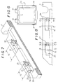
- Fig. 7 is a perspective view of a coupling portion of a shaft of the base;
- Fig. 8 is a plan view of the above;
- Fig. 9(A) is a sectional view taken on line B-B of Fig. 8;
- Fig. 9(B) is a sectional view taken on line C-C of Fig. 8;
- Fig. 9(C) is a sectional view taken on line D-D of Fig. 8;
- Fig. 9(D) is a sectional view taken on line E-E of Fig. 8;
- Fig. 9(E) is a sectional view taken on line F-F of Fig. 8;
- Fig. 9(F) is a sectional view taken on line G-G of Fig 8;
- Figs. 10(A) through 10(C) are plan views for explaining the steps for forming a shaft coupling by conforming the shaft portion to a recess portion;
- Fig. 11 is a plan view showing the IC carrier with an IC loaded thereon; and
- Fig. 12 is a sectional view showing an IC socket with the IC carrier loaded thereon.
- Figs. 1 through 12 show one embodiment of the present invention. This embodiment exemplifies a thin and flat IC carrier which is designed for the use of an
IC 5 holding anIC chip 4 by serving afilm 3 as shown in Fig. 11 as a carrier. - The IC carrier comprises a base 1 and a
cover 2, the base 1 is formed in a square frame plate, anIC accommodating section 6 is defined in an inner area along anopening portion 1a of the frame plate, a frame plate portion forming a bottom plate of theIC accommodating section 6 is served as a supportingplate 7 for supporting a peripheral portion of theIC 5, the supportingplate 7 is provided withpins 9 projecting therefrom and adapted to position theIC 5, and theIC positioning pins 9 are inserted intoholes 8 for positioning theIC 5 to hold theIC 5 on the base 1 while loading theIC 5 in theIC accommodating section 6 of the base 1. The supportingplate 7 is provided withpositioning holes 12 into which carrier positioning pins disposed on the side of anIC socket 10 shown in Fig. 12 are to be inserted. On the other hand, thecover 2 is formed of a square frame plate, the square frame plate is engaged with theIC accommodating section 6 to press the peripheral portion of theIC 5, and positioningholes 11, into which the IC carrier positioning pins disposed on the side of theIC socket 10 and theIC positioning pins 9 are to be inserted, are formed in a marginal portion along theopening portion 2a of the square frame plate. - As a shaft coupler for pivotally connecting the
cover 2 to the base 1 so that thecover 2 can be opened and closed (pivotable), a plurality ofshafts cover 2 at spaces in a projecting fashion. - The
shaft 13, as shown in Fig. 6, has a coaxis, and two of such shafts, for example, arranged in such a manner as to be projected in the same direction perpendicular to the pivoting direction of thecover 2. - On the other hand, a plurality of
short recess portions 15 shorter than the length of the shafts forming the shaft coupling andlong recess portions 16 equal to or longer than the length of the shafts are formed in one end of the base 1 at spaces in such a manner as to correspond to theshafts recess portions shaft inserting portions shafts - As is shown in Figs. 10(A) ad 10(B), the
cover 2 can be backwardly bent in the thick direction thereof, and by backwardly bending thecover 2, theshafts cover 2. - As is shown in Figs. 10(A), 10(B) and 10(C), the
shaft 14 corresponding to thelong recess portion 16 longer than the length of the shafts is inserted into theshaft inserting portion 18 at one end of therecess portion 16 via therecess portion 16. On the other hand, as is shown in Fig. 10(A) and 10(B), theshaft 13 corresponding to theshort recess portion 15 shorter than the length of the shafts is inserted into theshaft inserting portion 17 at one end of theshort recess portion 15 shorter than the length of the shafts when theshaft 13 is in its inclined state owing to bending motion of thecover 2 in the backward direction, and by restoring thebending cover 2 to its original state upon completion of the insertion of theshaft 13 as shown in Fig. 10(C), theshaft 13 is engaged in therecess portion 15, and anend face 19 of a basic end portion of theshaft 13 is contacted with the other end 20 (end face on the opposite side with respect to the shaft inserting portion 17) of therecess portion 15 in order to prevent theshafts shaft inserting portions shaft 14 is loosely inserted into theshaft inserting portion 18 within therecess portion 16 with a play formed in the slipping-out direction. - The
shaft inserting portions - As is shown in Fig. 9(A) and 9(D), the
recess portions inclined surfaces shafts recess portions circular shafts recess portions portions shafts shafts portions bottom surfaces shafts shafts shafts shaft inserting portions - The
short recess portion 15 shorter the length of the shaft is connected with an enlargedrecess portion 29 longer than the shaft formed at the entrance portion of theshaft 13. The enlargedrecess portion 29 is long on the opposite side with respect to theshaft inserting portion 17 of therecess portion 15, and astep portion 30 is formed between therecess portion 15 and the enlargedrecess portion 29 there. As is shown in Figs. 10(A) and 10(B), theshaft 13 is inclined in accordance with the backward bending motion of thecover 2 and brought into engagement with the enlargedrecess portion 29, the tip of theshaft 13, while supporting the basic end of theshaft 13 by thestep portion 30, is inclined and inserted into theshaft inserting portion 17, and by restoring the backwardly bending state of thecover 2, theshaft 13 is brought into engagement with therecess portion 15. That is to say, if thestep 30, which is necessarily formed at the entrance portion of therecess portion 15, exists, it can be practiced without a provision of the enlargedrecess portion 29. - Furthermore, in the above-mentioned embodiment, the
recess portions cover 2, as shown in Figs. 1, 2 and 10, is backwardly bent in the thick direction thereof in order to be brought into an erected state with respect to the base 1, and in that state, theshafts recess portions recess portions recess portions shafts recess portions - In this way, the
cover 2 is pivotably mounted to the base 1, a shaft coupling, which is not easily slipped out at any pivoting position is formed, and by closing thecover 2 relative to the base 1, the IC 5 can be held therebetween. In order to lock the holding state of the IC, for example, thecover 2 is engaged in theIC accommodating section 6,engaging projections 31 formed in the vicinity of the free end portion of the both sides of thecover 2 are snap engaged withprojections 32 formed on the corresponding both sides of theIC accommodating section 6, thereby to prevent thecover 2 from being accidentally pivoted in the opening direction. - As is shown in Fig. 12, the carrier carrying the
IC 5 is loaded on a table 34, which can be resiliently moved upward and downward, of thesocket 10, acontact 35 of thesocket 10 is inserted into acontact positioning hole 36, and by intimately contacting thepresser plate 37 with thesocket 10 to press the base 1, thecontact 35 is resiliently contacted with a contacting piece of theIC 5 through theopening portion 2a of thecover 2 as a reaction. - According to the present invention, the cover causes the shafts, while inclining the shafts owing to the backward bending motion of the cover, to be inserted into shaft inserting portions of corresponding short recess portions shorter than the length of the shafts, and the shafts are engaged in the recessed portions by the restoring motion of the cover to enhance an easy assembly of the shaft coupling. The shaft coupling can easily be disassembled by removing the shafts from the shaft inserting portions of the short recess portions shorter than the length of the shafts while bending the cover again in the backward direction.
- Owing to the foregoing arrangement, the cover cannot be inserted into nor removed from the recess portions unless the cover is bent backwardly. Accordingly, there is no such fear as to cause undesirable cancellation of the shaft coupling within a range of a pivotal movement of the cover. If the cover is bent backwardly while exhibiting the above-mentioned effect, cancellation of the shaft coupling can easily be realized.
Claims (6)
- An IC carrier comprising a base (1) and a cover (2) pivotably attached to said base through a shaft coupling, for holding an IC (5) by closing said cover relative to said base, one end of said cover (2) being provided with a plurality of shafts (13,14) forming said shaft coupling and arranged at spaced positions in a projecting fashion, one end of said base (1) being provided with a plurality of recess portions (15,16) including a short recess portion shorter (15) than the length of said shafts (13,14) forming said shaft coupling and a long recess portion equal to or longer than the length of said shafts (13,14), said short and long recess portions (15,16) being arranged at spaced positions, one end of said recess portions being provided with shaft inserting portions (17,18) for receiving tips of said shafts (13,14), said cover (2) being able to be bent in the thick direction thereof, said shafts (13,14) being able to be inclined in accordance with the bending motion of said cover, said shaft(s) (14) corresponding to said long recess portion(s) (16) equal to or longer than the length of said shafts being inserted into said shaft inserting portions (18) at one end of said recess portions via said recess portions (16), said shaft(s) (13) corresponding to said short recess portion(s) (15) shorter than the length of said shafts being inserted into said shaft inserting portion(s) (17) at one end of said short recess portion(s) (15) shorter than the length of said shafts when that shaft is inclined owing to bending motion of said cover, said shafts (13,14) being brought into engagement with said recess portions (15,16) owing to restoring motion of said cover (2).
- An IC carrier according to Claim 1 wherein said short recess portion (13) opens into an associated enlarged recess portion (29) longer than said shafts (13,14) and extending beyond the end of said short recess portion at the end thereof remote from the shaft inserting portion (17) associated with said short recess portion (13).
- An IC carrier according to Claim 2 wherein a step (30) is formed at said remote end of said short recess portion (13) between the end thereof and the corresponding end of said associated enlarged recess portion (29).
- An IC carrier according to any one of Claims 1 - 3, wherein end portions of said recess portions (15,16) adjacent the associated shaft inserting portions (17,18), are provided with arcuate bearing portions for seating bottom portions of the respective shafts.
- An IC carrier according to any one of Claims 1 - 4 wherein said shaft inserting portions (17,18) are provided with arcuate bearing portions for seating upper portions of the respective shafts.
- An IC carrier according to any one of Claims 1 - 5 wherein said recess portions (15,16) are formed with inclined surfaces (21,22) along side edges thereof to enlarge entry portions into the respective recess portions.
Applications Claiming Priority (3)
| Application Number | Priority Date | Filing Date | Title |
|---|---|---|---|
| JP333999/89 | 1989-12-22 | ||
| JP1333999A JPH0658998B2 (en) | 1989-12-22 | 1989-12-22 | IC carrier |
| SG149394A SG149394G (en) | 1989-12-22 | 1994-10-13 | IC carrier |
Publications (2)
| Publication Number | Publication Date |
|---|---|
| EP0434414A1 EP0434414A1 (en) | 1991-06-26 |
| EP0434414B1 true EP0434414B1 (en) | 1994-04-27 |
Family
ID=26574698
Family Applications (1)
| Application Number | Title | Priority Date | Filing Date |
|---|---|---|---|
| EP90313963A Expired - Lifetime EP0434414B1 (en) | 1989-12-22 | 1990-12-19 | IC carrier |
Country Status (5)
| Country | Link |
|---|---|
| US (1) | US5109980A (en) |
| EP (1) | EP0434414B1 (en) |
| JP (1) | JPH0658998B2 (en) |
| DE (1) | DE69008500D1 (en) |
| SG (1) | SG149394G (en) |
Families Citing this family (37)
| Publication number | Priority date | Publication date | Assignee | Title |
|---|---|---|---|---|
| US5485351A (en) * | 1989-06-09 | 1996-01-16 | Labinal Components And Systems, Inc. | Socket assembly for integrated circuit chip package |
| JPH04329279A (en) * | 1991-04-30 | 1992-11-18 | Yamaichi Electron Co Ltd | Socket for electric part |
| JPH0675416B2 (en) * | 1991-12-20 | 1994-09-21 | 山一電機株式会社 | Connector |
| US5247250A (en) * | 1992-03-27 | 1993-09-21 | Minnesota Mining And Manufacturing Company | Integrated circuit test socket |
| JPH0763082B2 (en) * | 1993-02-15 | 1995-07-05 | 山一電機株式会社 | IC carrier |
| JPH07121758B2 (en) * | 1993-03-12 | 1995-12-25 | 山一電機株式会社 | IC carrier |
| IT229919Y1 (en) * | 1993-05-19 | 1999-02-05 | Lt Terraneo Spa | MODULAR AND MODULAR VIDEO DOOR ENTRY PANEL FOR WIRING |
| US5344334A (en) * | 1993-06-11 | 1994-09-06 | The Whitaker Corporation | Hinged cover for an electrical socket |
| FR2707433B1 (en) * | 1993-07-08 | 1995-08-18 | Pontarlier Connectors | Card connector, in particular for electronic card. |
| JP2544084B2 (en) * | 1993-12-28 | 1996-10-16 | 山一電機株式会社 | Connector for electrical parts |
| JP2655827B2 (en) * | 1995-04-17 | 1997-09-24 | 山一電機株式会社 | IC carrier |
| JP2768920B2 (en) * | 1995-08-11 | 1998-06-25 | 山一電機株式会社 | IC carrier |
| US5791914A (en) * | 1995-11-21 | 1998-08-11 | Loranger International Corporation | Electrical socket with floating guide plate |
| US5647750A (en) * | 1995-11-30 | 1997-07-15 | The Whitaker Corporation | Socket for a tape carrier package |
| JP3292038B2 (en) * | 1996-05-31 | 2002-06-17 | 日産自動車株式会社 | Storage |
| US6050442A (en) * | 1996-09-27 | 2000-04-18 | Cascade Engineering, Inc. | Multi-compartment containers, hinged lid and divider assemblies therefor, and hinge assemblies |
| US5762200A (en) * | 1997-07-16 | 1998-06-09 | Eastern Container Companies | Product suspension packing |
| US5969245A (en) * | 1998-05-05 | 1999-10-19 | Primax Electronics Ltd. | Scanner casing |
| TW370324U (en) * | 1998-06-17 | 1999-09-11 | Primax Electronics Ltd | Platform scanner document press |
| USD430024S (en) * | 1998-11-04 | 2000-08-29 | Affymetrix, Inc. | Chip packaging device |
| US6065626A (en) * | 1998-12-08 | 2000-05-23 | Huang; Chien Jung | Box opening/closing structure |
| JP2000180469A (en) * | 1998-12-18 | 2000-06-30 | Fujitsu Ltd | Contactor for semiconductor device, tester using contactor for semiconductor device, testing method using contactor for semiconductor device and method for cleaning contactor for semiconductor device |
| JP2001185306A (en) * | 1999-12-28 | 2001-07-06 | Jst Mfg Co Ltd | Connector for module |
| US6474477B1 (en) | 2001-05-02 | 2002-11-05 | Ching T. Chang | Carrier assembly for semiconductor IC (integrated circuit) packages |
| US6692280B2 (en) * | 2001-09-28 | 2004-02-17 | Intel Corporation | Socket warpage reduction apparatus and method |
| TW549762U (en) * | 2002-07-18 | 2003-08-21 | Benq Corp | Electronic device having electronic card |
| TW549655U (en) * | 2002-12-20 | 2003-08-21 | Hon Hai Prec Ind Co Ltd | An electrical connector |
| TW580207U (en) * | 2003-03-05 | 2004-03-11 | Hon Hai Prec Ind Co Ltd | Electrical connector assembly |
| CN2728014Y (en) * | 2004-07-02 | 2005-09-21 | 富士康(昆山)电脑接插件有限公司 | Electric connection assembly |
| JP5392807B2 (en) * | 2007-06-05 | 2014-01-22 | サカセ化学工業株式会社 | Electronic parts carrying case |
| US7861458B2 (en) * | 2007-12-13 | 2011-01-04 | Rehrig Pacific Company | Collapsible container |
| US8561976B2 (en) * | 2008-03-27 | 2013-10-22 | American Panel Corporation | Transportable carrier compatable with a retractable pin tool |
| CA2809709C (en) * | 2013-03-14 | 2018-02-13 | Cledlight Semiconductor Lighting Co., Ltd. | Rotational mounting for linear led light |
| TW201446101A (en) * | 2013-05-30 | 2014-12-01 | Hon Hai Prec Ind Co Ltd | Carrying device |
| US9717156B2 (en) * | 2015-07-03 | 2017-07-25 | Lotes Co., Ltd | Electrical socket connector with guide frame IC chip placement |
| US10703531B2 (en) | 2016-03-11 | 2020-07-07 | Rehrig Pacific Company | Collapsible crate with wood appearance |
| US11597557B2 (en) | 2018-10-04 | 2023-03-07 | Rehrig Pacific Company | Reconfigurable beverage crate |
Family Cites Families (15)
| Publication number | Priority date | Publication date | Assignee | Title |
|---|---|---|---|---|
| US3391383A (en) * | 1966-06-20 | 1968-07-02 | Hughes Aircraft Co | Electrical connector for integrated circuit elements |
| US4007479A (en) * | 1976-03-29 | 1977-02-08 | Honeywell Information Systems, Inc. | Fixture for an integrated circuit chip |
| US4307819A (en) * | 1980-02-28 | 1981-12-29 | Yukio Araki | Box comprising main portion and lid portion pivotably connected to main portion |
| US4477991A (en) * | 1981-12-24 | 1984-10-23 | Polaroid Corporation | Frame for transparency film |
| JPS59135699U (en) * | 1983-02-28 | 1984-09-10 | 山一電機工業株式会社 | IC holding device in IC socket |
| JPS6010310A (en) * | 1983-06-29 | 1985-01-19 | Nippon Denshi Kagaku Kk | Robot controller |
| JPS60146089A (en) * | 1984-01-06 | 1985-08-01 | 帝人株式会社 | Ombre printed fiber structure |
| GB2164213B (en) * | 1984-09-06 | 1988-07-13 | Nec Corp | Structure for connecting leadless chip carrier |
| CA1233305A (en) * | 1984-11-30 | 1988-03-01 | W.S. Dominic Ng | Hinge structure |
| JPH0219421Y2 (en) * | 1984-12-30 | 1990-05-29 | ||
| JPH0237752Y2 (en) * | 1985-05-21 | 1990-10-12 | ||
| JPS61278159A (en) * | 1985-06-03 | 1986-12-09 | Yamaichi Electric Mfg Co Ltd | Carrier for ic package |
| US4663803A (en) * | 1986-04-15 | 1987-05-12 | Menasha Corporation | Security hinge joint with separate hinge pin |
| US4706161A (en) * | 1986-11-17 | 1987-11-10 | Minnesota Mining And Manufacturing Company | Device protective apparatus |
| US4925059A (en) * | 1989-03-20 | 1990-05-15 | International Packaging Corporation | Hinged box construction |
-
1989
- 1989-12-22 JP JP1333999A patent/JPH0658998B2/en not_active Expired - Fee Related
-
1990
- 1990-12-19 EP EP90313963A patent/EP0434414B1/en not_active Expired - Lifetime
- 1990-12-19 DE DE69008500T patent/DE69008500D1/en not_active Expired - Lifetime
- 1990-12-20 US US07/631,676 patent/US5109980A/en not_active Expired - Lifetime
-
1994
- 1994-10-13 SG SG149394A patent/SG149394G/en unknown
Also Published As
| Publication number | Publication date |
|---|---|
| JPH0658998B2 (en) | 1994-08-03 |
| EP0434414A1 (en) | 1991-06-26 |
| DE69008500D1 (en) | 1994-06-01 |
| US5109980A (en) | 1992-05-05 |
| SG149394G (en) | 1995-03-17 |
| JPH03195000A (en) | 1991-08-26 |
Similar Documents
| Publication | Publication Date | Title |
|---|---|---|
| EP0434414B1 (en) | IC carrier | |
| US6890203B2 (en) | Card connector reduced in operating force | |
| JPH09185973A (en) | Connector for card with surface contact | |
| JPH02227974A (en) | Double lock structure of connector housing | |
| JP2670517B2 (en) | Contact mechanism for IC carrier mounted socket | |
| KR100380249B1 (en) | Method of operating plastic clip, and plastic clip using same method | |
| US5373938A (en) | IC accommodation apparatus having retaining latches | |
| JP4172856B2 (en) | IC socket | |
| JPH0237752Y2 (en) | ||
| JPH0217308B2 (en) | ||
| JP2580074Y2 (en) | Electrical connector for flexible board | |
| CA2032552A1 (en) | Ic carrier | |
| JPH0353471A (en) | Electric connector | |
| JP2659924B2 (en) | IC socket | |
| KR100216312B1 (en) | Socket for electric part | |
| JPS58131681A (en) | Plug retaining mechanism for socket | |
| JPH0210637Y2 (en) | ||
| JPH0782941A (en) | Rock spring for opening lid | |
| JP3513422B2 (en) | Portable watch | |
| EP0390542A2 (en) | IC carrier | |
| JPH064541Y2 (en) | Terminal block | |
| KR850000508Y1 (en) | A watch band | |
| JPH0733414Y2 (en) | IC socket | |
| JPS6338594Y2 (en) | ||
| JPH10270868A (en) | Cover opening/closing structure |
Legal Events
| Date | Code | Title | Description |
|---|---|---|---|
| PUAI | Public reference made under article 153(3) epc to a published international application that has entered the european phase |
Free format text: ORIGINAL CODE: 0009012 |
|
| AK | Designated contracting states |
Kind code of ref document: A1 Designated state(s): DE FR GB IT |
|
| 17P | Request for examination filed |
Effective date: 19910910 |
|
| 17Q | First examination report despatched |
Effective date: 19930806 |
|
| GRAA | (expected) grant |
Free format text: ORIGINAL CODE: 0009210 |
|
| AK | Designated contracting states |
Kind code of ref document: B1 Designated state(s): DE FR GB IT |
|
| PG25 | Lapsed in a contracting state [announced via postgrant information from national office to epo] |
Ref country code: DE Effective date: 19940427 |
|
| ET | Fr: translation filed | ||
| REF | Corresponds to: |
Ref document number: 69008500 Country of ref document: DE Date of ref document: 19940601 |
|
| ITF | It: translation for a ep patent filed |
Owner name: ORGANIZZAZIONE D'AGOSTINI |
|
| RAP2 | Party data changed (patent owner data changed or rights of a patent transferred) |
Owner name: YAMAICHI ELECTRONICS CO., LTD. |
|
| RAP4 | Party data changed (patent owner data changed or rights of a patent transferred) |
Owner name: YAMAICHI ELECTRONICS CO., LTD. |
|
| PLBE | No opposition filed within time limit |
Free format text: ORIGINAL CODE: 0009261 |
|
| STAA | Information on the status of an ep patent application or granted ep patent |
Free format text: STATUS: NO OPPOSITION FILED WITHIN TIME LIMIT |
|
| 26N | No opposition filed | ||
| PG25 | Lapsed in a contracting state [announced via postgrant information from national office to epo] |
Ref country code: FR Effective date: 19950831 |
|
| REG | Reference to a national code |
Ref country code: FR Ref legal event code: ST |
|
| PGFP | Annual fee paid to national office [announced via postgrant information from national office to epo] |
Ref country code: GB Payment date: 19951211 Year of fee payment: 6 |
|
| PG25 | Lapsed in a contracting state [announced via postgrant information from national office to epo] |
Ref country code: GB Effective date: 19961219 |
|
| GBPC | Gb: european patent ceased through non-payment of renewal fee |
Effective date: 19961219 |
|
| PG25 | Lapsed in a contracting state [announced via postgrant information from national office to epo] |
Ref country code: IT Free format text: LAPSE BECAUSE OF NON-PAYMENT OF DUE FEES Effective date: 20051219 |