EP0438476B1 - Self-clocking encoding/decoding film information exchange system using dedicated magnetic tracks on film - Google Patents
Self-clocking encoding/decoding film information exchange system using dedicated magnetic tracks on film Download PDFInfo
- Publication number
- EP0438476B1 EP0438476B1 EP89911663A EP89911663A EP0438476B1 EP 0438476 B1 EP0438476 B1 EP 0438476B1 EP 89911663 A EP89911663 A EP 89911663A EP 89911663 A EP89911663 A EP 89911663A EP 0438476 B1 EP0438476 B1 EP 0438476B1
- Authority
- EP
- European Patent Office
- Prior art keywords
- film
- tracks
- camera
- track
- data
- Prior art date
- Legal status (The legal status is an assumption and is not a legal conclusion. Google has not performed a legal analysis and makes no representation as to the accuracy of the status listed.)
- Expired - Lifetime
Links
- 230000005291 magnetic effect Effects 0.000 title claims abstract description 73
- 238000000034 method Methods 0.000 claims description 13
- 238000012545 processing Methods 0.000 claims description 9
- 238000007689 inspection Methods 0.000 claims description 8
- 230000008569 process Effects 0.000 claims description 8
- 238000007639 printing Methods 0.000 claims description 4
- 238000004891 communication Methods 0.000 claims description 3
- 230000000295 complement effect Effects 0.000 claims description 2
- 230000015654 memory Effects 0.000 description 26
- 230000007704 transition Effects 0.000 description 15
- 230000032258 transport Effects 0.000 description 10
- 238000010586 diagram Methods 0.000 description 8
- 238000012937 correction Methods 0.000 description 5
- 230000008901 benefit Effects 0.000 description 4
- 230000000063 preceeding effect Effects 0.000 description 4
- 230000004308 accommodation Effects 0.000 description 2
- 239000000872 buffer Substances 0.000 description 2
- 230000000694 effects Effects 0.000 description 2
- 230000003287 optical effect Effects 0.000 description 2
- 230000002123 temporal effect Effects 0.000 description 2
- 238000004804 winding Methods 0.000 description 2
- 230000002411 adverse Effects 0.000 description 1
- 230000003139 buffering effect Effects 0.000 description 1
- 238000013461 design Methods 0.000 description 1
- 238000001514 detection method Methods 0.000 description 1
- 239000000839 emulsion Substances 0.000 description 1
- 238000005516 engineering process Methods 0.000 description 1
- 230000003116 impacting effect Effects 0.000 description 1
- 230000001050 lubricating effect Effects 0.000 description 1
- 238000012986 modification Methods 0.000 description 1
- 230000004048 modification Effects 0.000 description 1
- 230000000737 periodic effect Effects 0.000 description 1
- 239000000126 substance Substances 0.000 description 1
Images


Classifications
-
- G—PHYSICS
- G11—INFORMATION STORAGE
- G11B—INFORMATION STORAGE BASED ON RELATIVE MOVEMENT BETWEEN RECORD CARRIER AND TRANSDUCER
- G11B23/00—Record carriers not specific to the method of recording or reproducing; Accessories, e.g. containers, specially adapted for co-operation with the recording or reproducing apparatus ; Intermediate mediums; Apparatus or processes specially adapted for their manufacture
- G11B23/38—Visual features other than those contained in record tracks or represented by sprocket holes the visual signals being auxiliary signals
- G11B23/44—Information for display simultaneously with playback of the record, e.g. photographic matter
-
- G—PHYSICS
- G03—PHOTOGRAPHY; CINEMATOGRAPHY; ANALOGOUS TECHNIQUES USING WAVES OTHER THAN OPTICAL WAVES; ELECTROGRAPHY; HOLOGRAPHY
- G03D—APPARATUS FOR PROCESSING EXPOSED PHOTOGRAPHIC MATERIALS; ACCESSORIES THEREFOR
- G03D15/00—Apparatus for treating processed material
- G03D15/001—Counting; Classifying; Marking
- G03D15/003—Marking, e.g. for re-printing
-
- G—PHYSICS
- G03—PHOTOGRAPHY; CINEMATOGRAPHY; ANALOGOUS TECHNIQUES USING WAVES OTHER THAN OPTICAL WAVES; ELECTROGRAPHY; HOLOGRAPHY
- G03B—APPARATUS OR ARRANGEMENTS FOR TAKING PHOTOGRAPHS OR FOR PROJECTING OR VIEWING THEM; APPARATUS OR ARRANGEMENTS EMPLOYING ANALOGOUS TECHNIQUES USING WAVES OTHER THAN OPTICAL WAVES; ACCESSORIES THEREFOR
- G03B17/00—Details of cameras or camera bodies; Accessories therefor
- G03B17/24—Details of cameras or camera bodies; Accessories therefor with means for separately producing marks on the film, e.g. title, time of exposure
-
- G—PHYSICS
- G03—PHOTOGRAPHY; CINEMATOGRAPHY; ANALOGOUS TECHNIQUES USING WAVES OTHER THAN OPTICAL WAVES; ELECTROGRAPHY; HOLOGRAPHY
- G03B—APPARATUS OR ARRANGEMENTS FOR TAKING PHOTOGRAPHS OR FOR PROJECTING OR VIEWING THEM; APPARATUS OR ARRANGEMENTS EMPLOYING ANALOGOUS TECHNIQUES USING WAVES OTHER THAN OPTICAL WAVES; ACCESSORIES THEREFOR
- G03B2206/00—Systems for exchange of information between different pieces of apparatus, e.g. for exchanging trimming information, for photo finishing
- G03B2206/004—Systems for exchange of information between different pieces of apparatus, e.g. for exchanging trimming information, for photo finishing using markings on the photographic material, e.g. to indicate pseudo-panoramic exposure
-
- G—PHYSICS
- G03—PHOTOGRAPHY; CINEMATOGRAPHY; ANALOGOUS TECHNIQUES USING WAVES OTHER THAN OPTICAL WAVES; ELECTROGRAPHY; HOLOGRAPHY
- G03B—APPARATUS OR ARRANGEMENTS FOR TAKING PHOTOGRAPHS OR FOR PROJECTING OR VIEWING THEM; APPARATUS OR ARRANGEMENTS EMPLOYING ANALOGOUS TECHNIQUES USING WAVES OTHER THAN OPTICAL WAVES; ACCESSORIES THEREFOR
- G03B2217/00—Details of cameras or camera bodies; Accessories therefor
- G03B2217/24—Details of cameras or camera bodies; Accessories therefor with means for separately producing marks on the film
- G03B2217/242—Details of the marking device
- G03B2217/244—Magnetic devices
-
- G—PHYSICS
- G03—PHOTOGRAPHY; CINEMATOGRAPHY; ANALOGOUS TECHNIQUES USING WAVES OTHER THAN OPTICAL WAVES; ELECTROGRAPHY; HOLOGRAPHY
- G03B—APPARATUS OR ARRANGEMENTS FOR TAKING PHOTOGRAPHS OR FOR PROJECTING OR VIEWING THEM; APPARATUS OR ARRANGEMENTS EMPLOYING ANALOGOUS TECHNIQUES USING WAVES OTHER THAN OPTICAL WAVES; ACCESSORIES THEREFOR
- G03B2217/00—Details of cameras or camera bodies; Accessories therefor
- G03B2217/24—Details of cameras or camera bodies; Accessories therefor with means for separately producing marks on the film
- G03B2217/246—Details of the markings
Definitions
- scene-related information is typically lost or forgotten.
- Such information may include the user's desire to not have a particular frame printed or to have several prints made from a given frame, for example.
- Such information may also include the photographic parameters of the scene, observed by the user or by a sensor, which would have aided the photofinisher's classification of the scene to increase the quality of the prints made from the film.
- the film processing equipment must lie dormant for a period of time at the beginning of each work day until enough incoming customer film has been sorted to form one batch of a minimum number (e.g. 70) of film strips of the same type (such as color negative 35 mm film) to justify running the printing equipment.
- a minimum number e.g. 70
- undeveloped film regular customer orders
- printed film print re-orders
- More significant sources of inefficiency in the photofinishing process include the mechanical steps required to maintain proper correspondence between each film strip and the prints made from it, as well as the customer's identity. These mechanical steps include the sorting and handling of each form or envelope originally filled out by the customer so that the envelope follows the customer's film strip throughout the photofinishing process and winds up with the corresponding set of prints.
- the mechanical steps include notching the prints to indicate the boundaries between adjacent prints and between adjacent orders on a roll of prints as well as marking any original print requiring a makeover in a labor intensive procedure which ensures that proper correspondence between each film strip and the corresponding original prints, makeover prints and customer order form (envelope) is never lost.
- a problem underlying all of the foregoing is that neither the camera nor any particular stage of the photofinisher may be relied upon to transport the film at some pre-defined velocity while data is being recorded or read, nor even at a uniform velocity.
- clocking or velocity information be recorded in a separate track each time data is recorded in one of the dedicated tracks. Such a requirement would complicate the recording process, making it less reliable, and reduce the area on the film available for recording information.
- Another problem is how to provide the photofinisher with an automatic indication whenever a particular film strip has been spliced in a roll of film strips but rotated (either end-for-end or emulsion side up) with respect to its original orientation (as established during data recording in the camera or at an order entry station).
- film formats e.g. 110 or 126 film
- the problem here is how to permit the photofinisher to use magnetic recording on film without regard to the format of the film or the type of camera used, using the same magnetic recording format and hardware for all cases. Solving this last problem would permit all film for all cameras to include the additional magnetic layer, for photofinishing with the same magnetic read/write format and automated protocols using the film magnetic layer as a frame-by-frame scratch pad memory.
- a film strip and a data communication apparatus for processing a film strip as defined in Claims 1 and 3.
- magnetic reading and writing of information in a virtually transparent magnetic layer in the film during each stage of film used and film processing is restricted to certain dedicated parallel tracks extending longitudinally along the length of the film, the choice of track being determined in accordance with the particular information being recorded.
- Magnetic reading/writing is performed with transport of the film by the camera during field use and during transport of the film by the dealer or photofinisher during film processing, printing, etc.
- the tracks are dedicated by universal pre-arrangement to certain sets of parameters or information, each set being of particular interest to a certain stage in the use of the film, the various stages including the camera, the dealer order entry station, the photofinisher order entry station, the classifier, the printer, the inspection or re-classifier station and the enveloper-sorter station.
- the photofinisher tracks occupy the principal image area of each frame, so as to maximize the number of tracks available to the photofinisher and to render the format of these tracks virtually immune to any differences between various film formats or film perforation patterns.
- the photofinisher tracks therefore have a universally applicable format for use not just in photofinishing but also in film-to-video players, electronic print processing, etc.
- the camera tracks are present only in film adapted for use in cameras having magnetic read/write capability.
- the camera tracks are accommodated along the film edges, without impacting the photofinisher track locations, by interruption of the usual film perforation pattern along the film edges.
- each perforation is located next to the image area while the camera tracks are located next to the image area along the film edges between successive perforations.
- All data is magnetically recorded on the film using a novel self-clocking code which is completely self-clocking, in order to provide automatic data synchronization between the various users without requiring any of them to transport the film at the same speed or even at a uniform speed when reading and writing.
- the self-clocking code is a single channel comprising a succession of uniform clocking pulses with intervening data transition pulses. The temporal placement of each data transition pulse relative only to the two clocking pulses which immediately preceed it and follow it, respectively, determines whether that transition pulse corresponds to a binary one or zero.
- film transport velocity changes between the recording of successive binary bits have no effect upon the information content of the self-clocking encoded data. More importantly, differences in film transport velocity between data recording and data playback have no effect upon the readability of the self-clocking encoded data.
- the various types of information are allocated among the dedicated tracks in accordance with groups of related information types or parameters, some individual groups being used by more than one stage of the film use cycle.
- information common to all frames of the film is in dedicated tracks on the film leader. Specifically, information common to all frames, such as film type, camera type, owner identification, a directory of written information and the like are recorded in a first camera track (near one film edge) on the film leader. This first camera track is designated track C0 while the film leader is designated frame 0.
- Scene related parameters automatically sensed by the camera (such as scene luminance, camera orientation, color temperature, flash fire, etc.) are recorded in track C0 in each subsequent frame (e.g. frames 1-25).
- a second camera track, track C1 is dedicated to the recording of secondary information, such as shutter speed, aperture size, etc.
- secondary information such as shutter speed, aperture size, etc.
- an intelligent photofinishing classifier station in attempting to compute the optimum exposure conditions to make a print, would read the data on track C0 in each of frames 1 through 24 (for example), while a finishing station, in attempting to maintain correspondence between a customer's film and his order form or envelope, would read the data on track C0 in frame 0.
- a similar sort of allocation of photofinisher dedicated tracks is employed, with customer print order request data being recorded in a first photofinisher track (F0) in frame 0, process data such as image classification and number of prints made by frame in track F01, frames 1-25 (for example). Any makeover correction is recorded in track F02.
- a summary of makeover data (e.g. total number of makeover prints) is recorded in track F2 in frame 0.
- Other photofinisher tracks may be dedicated to uses other than photofinishing, such as frame-by-frame user instructions for
- the invention solves the problem of attaining data synchronization at all stages of film use without requiring that each stage transport the film at constant velocity nor even at the same velocity while recording or playing back data.
- the invention achieves this without requiring the recording of an extra space-wasting clocking track simultaneously with the data track.
- the representation of the binary state of a particular bit is unaffected by the film transport speed during recording and playback and is self-clocking. This representation uniquely depends upon the temporal relationship between each data transition pulse and its immediately preceeding and succeeding clock pulses in the serial pulse train comprising the self-clocking code.
- a one bit is represented by a data transition pulse which is closer to the preceeding clock pulse. For a zero bit, the data transition pulse is closer to the succeeding clock pulse.
- the invention solves the data access problem faced by (among others) the photofinisher of "finding a needle in a haystack" because each stage need merely know which track has been dedicated to the data relevant to that stage, and may read the data from that track while ignoring all other data magnetically recorded on the film. Furthermore, in some cases the reading of data can be dispensed with entirely in order to make certain basic determinations about the film, by simply determining whether certain tracks are empty or not. For example, whether a particular strip of film has already been developed (and therefore was submitted for print re-order) is readily determined by seeing whether or not certain tracks (e.g. track F1 of frames 1 - 24) contain recorded data or not.
- tracks e.g. track F1 of frames 1 - 24
- a strip 100 of color negative film 35 millimeters wide includes a base 110, various well-known photo-chemical layers 115 on one side of the base 110 and a virtually transparent magnetic layer 120 on the other side.
- An anti-static and lubricating layer 122 overlies the magnetic layer 120.
- the film strip 100 includes perforations 125 spaced along the film edge at regular intervals matching the pitch of a metering pawl in a camera adapted to use the film strip 100.
- each frame of the film strip 100 is divided into a plurality of predetermined parallel longitudinal track locations where magnetic tracks of data may be recorded.
- Each of the tracks is preferably labeled as shown in Fig. 1.
- the two outermost tracks along each edge of the film strip 100 are tracks C0, C1 and tracks C2, C3, respectively.
- the thirty innermost tracks are tracks F00 through F29.
- Each one of the outermost tracks C0 through C3 is dedicated to the recording of a particular type of information by a camera having magnetic recording capability, in accordance with a pre-arrangement universally established for all cameras and photofinishers.
- each one of the innermost tracks is dedicated to the recording of a particular type of information by a particular type of photofinishing (or other) equipment, in accordance with the above-referenced universal pre-arrangement.
- the perforations 125 are excluded from periodic imperforate edge regions 100a adjacent each exposed frame and are restricted to intermediate regions 100b lying between subsequent frames. In the embodiment of Fig. 1, there is only one perforation in each intermediate region 100b. In the preferred embodiment, the perforations lie along only one longitudinal edge of the film strip 100.
- a camera 200 transports the film strip 100 between the reels 205a,b, of a film cartridge and a take-up sprocket, respectively, conforming to the format of the perforations 125 of Fig. 1.
- the camera 200 includes a magnetic read/write head 210 in near proximity with the magnetic layer 120 on the unsensitized side of the film strip 100.
- a microprocessor 215 controls magnetic data recording or playback by the head 210 through head electronics 220.
- the microprocessor 215 may accept order information to be magnetically recorded on the film strip 100 from the camera user through camera controls 225, such information pertaining to the number of prints desired for a given frame, by frame number, for example, or the name and address of the camera user for ultimate use by the photofinisher.
- the microprocessor 215 may also accept scene related information from scene sensors 230 to be magnetically recorded on the film strip 100 for ultimate use by the photofinisher. Such information may include camera orientation, scene luminance and the like.
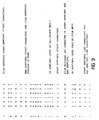
- the self-clocking code described in the referenced patent application is briefly summarized here with reference to Fig. 12 of the accompanying drawings.
- the code comprises a serial stream of pulse edge transitions of a first type (e.g. positive-going edge transitions) and those of a second type (e.g. negative-going edge transitions) in alternating sequence.
- the first type pulse transitions serve as clock indicators while the second type serve as binary data indicators.
- a binary one is indicated in Fig 12a by a second type pulse transition 1215 which is temporally closer to the immediately preceeding first type pulse transition 1205 and farther from the succeeding first type pulse transition 1210.
- a binary zero is indicated in Fig.
- the self-clocking code of Fig. 12 facilitates the automatic detection of film reversal.
- two six-bit characters from the table of reserved characters of Fig. 9 are chosen as the start and stop sentinels, respectively, recorded at the beginning and end of each frame in each dedicated track, in a manner described herein with reference to Fig. 6.
- the compliments of the two symbols thus chosen are also reserved, as indicated in Fig. 13, the latter two reserved symbols comprising a film-reversed start sentinel and a film-reversed stop sentinel.
- This arrangement exploits a property of the self-clocking code of Fig. 12 in which self-clocking data played back backwards (by transporting the film past the head in the direction opposite from that in which it was transported earlier during recording) results in its complement being decoded.
- Fig. 14a corresponds to the orientation of the film during the magnetic recording of data on the film by the camera for example
- Fig. 14b corresponds to the orientation of the film as it is spliced and loaded into photofinishing equipment having magnetic read/write capability
- the film reversed stop sentinel will be detected, followed by the film reversed start sentinel, with every frame of data.
- Such film-reversed start and stop sentinels serve as flags to notify the photofinisher that the film has been rotated as indicated in Fig. 14b.
- the technique of Fig. 13 does not create a flag.
- such an error is easily detected, since it causes the opposite side of the film to face the photofinisher's magnetic heads, thus increasing the distance between the heads and the magnetic layer 120 of Fig. 1, resulting in a decrease in signal-to-noise ratio.
- Fig. 15 illustrates a simple example of a magnetics on film self-clocking read/write system useful in the camera 200 of Fig. 2.
- the advantage of the longitudinal dedicated track format of Fig. 1 is that magnetic recording of data on the film strip 100 may be performed by the camera using a relatively stationary head (i.e. the head 210) by buffering all of the data to be recorded in a particular frame in a particular camera track and then transmitting the data to the head just as the film is being wound to the next frame.
- a relatively stationary head i.e. the head 210
- the microprocessor 215 includes a read only memory 240 containing instructions sufficient to ensure that each type of information received is recorded in the correct one of the dedicated camera tracks C0 - C3 in accordance with a universal pre-arrangement common to both the camera and the photofinisher. For this purpose, the microprocessor sorts and buffers each piece of information in compliance with the instructions stored in the read only memory 240. The nature of this pre-arrangement and the architecture of the read only memory will be described below in this specification.
- the format of the photofinisher tracks F00 through F29 is the same regardless of the placement of the film perforations 125 of Fig. 1.
- a photofinisher may employ the same magnetic recording protocols and hardware on all types of film provided that a virtually transparent magnetic layer (such as the layer 120 of Fig. 1) is added to all types of film.
- a virtually transparent magnetic layer such as the layer 120 of Fig. 1
- ordinary 35 mm color negative film having the now-standard pattern of closely spaced perforations along both film edges accommodates the photofinisher tracks F00 through F29 having the same width and spacing as that of the special film format of Fig. 1.
- the perforations of Fig. 3 preclude the presence of the camera tracks C0 through C3, such film is not used in cameras having magnetic read/write capabilities and so the camera tracks need not be present.
- the advantage here is that all subsequent users of the film (i.e. photofinisher, film-to-video player, etc.) have been allocated the maximum number of tracks for all film formats, including those of Fig. 1
- the width of the camera dedicated tracks C0 - C3 is greater than that of the photofinisher tracks F00 - F29.
- these track widths are controlled by the selection of the camera head widths and the photofinisher head widths.
- the difference is sufficient to accommodate film wander in the camera during winding of the film while recording is performed by the head 210. Such wandering causes the camera tracks to have the meandering appearance illustrated in Fig. 4. Note in Fig. 4 that the photofinisher head, which must read the camera tracks, does not leave the camera track because it has a much smaller width.
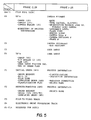
- Fig. 5 illustrates the allocation of the dedicated tracks, among the various information types, implemented by microcodes stored in the read only memory 240 of Fig. 2.
- the film leader and trailer are designated frames 0 and 26, respectively.
- the information recorded in frames 0 and 26 pertains to the film strip 100 as a whole, while the information recorded in each of frames 1 through 25 is unique for a particular frame.
- three of the four camera tracks are used by the camera, while three of the thirty photofinisher tracks are used by the photofinisher.
- the rest of the photofinisher tracks are reserved for the recording of film-to-video player instructions (track F03), electronic print processing instructions (track F04) and audio (track F05 through F14).
- the remaining tracks (F15 - F29) are reserved for unforeseen purposes.
- each of the tracks is dedicated to a particular group of information types which would in most cases be written or read together.
- frame 0 track C0 is reserved for information relating to the owner and the camera for recording by the camera.
- frame 0 track F00 is reserved for information relating to the owner and the photofinisher for recording by the photofinisher.
- track F00 of frame 0 is reserved for recording by the photofinisher--or by an order entry station--of the customer's instructions, the film type, and related information pertaining to the treatment of the order.
- Track F02 of frame 0 is reserved for the recording of historical information regarding the location of frames requiring makeover prints and print reorders by the customer, for use by the photofinisher during a subsequent print reorder by the customer.
- Track C0 of each exposed frame (frames 1-25) is reserved for scene-related information for recording by the camera, such as scene luminance, camera orientation and the like.
- track F01 is reserved for photofinisher information unique to a particular exposed frame such as the classification of the negative image (determination of the proper print exposure), number of prints made, etc. Any makeover correction to the classification is recorded in track F02.
- the embodiment of Fig. 5 does not take into account all of the information types which may be magnetically recorded by the camera, retail order station or photofinisher on the film.
- the embodiment of Fig. 5 is an example of the manner in which all information types may be classified as to which track each one is to be assigned.
- the principle underlying the manner in which each information type is assigned to a particular track is that all information related to a particular transaction should be recorded on the same track, so that that track is dedicated to being written or read during those operations associated with that transaction.
- the various transactions provided for in the embodiment of Fig. 5 are: (a) recording of customer data, including the customer address; (b) recording of scene-related information with each exposure, including parameters characterizing lighting conditions and camera exposure settings; (c) recording by the retail order station or photofinisher of customer order information, such as the number of prints desired; (d) the recording of inspection and makeover classification correction for a given frame by the photofinisher; (e) the recording of a summary of makeover data or print reorder data applicable to the entire film roll; (f) the recording of instructions for a film to video player; (g) the recording of instructions for electronic print processing; and (h) the recording of audio.
- the data recorded magnetically on the film strip 100 is divided into frames exposed by the camera (frames 1-25) as well as the film leader (frame 0), the data within each frame being allocated among a plurality of dedicated tracks within the frame.
- Fig. 6 illustrates the preferred data format within each track of each frame.
- each track 600 has the length of one frame and is divided into a plurality of fields 610.
- Each track 600 includes a predicate start sentinel 615 at its beginning end (the left-hand edge of the track in Fig. 6 where the head begins its scanning of the track 600) and a stop sentinel 640 at its end.
- Each field includes a predicate ID sentinel 620 followed immediately by an ID code 625.
- the purpose of the track start sentinel 615 is to notify the read/write system in the camera or in the photofinishing hardware of the beginning location of the track 600.
- the purpose of the field ID sentinel 620 is to notify the same system of the beginning location of each succeeding field in the track 600.
- each start sentinel 615 is preceeded by a start sync mark 616 and each end sentinel 640 is followed by a stop sync mark 641.
- the marks 616, 641 enable special circuitry to achieve proper synchronization under adverse conditions described therein.
- the ID code is recorded in the beginning of each field and is determined by the information type which follows it. For example, if the camera 200 of Fig. 2 is about to record the level of scene luminance observed by sensors on the camera during exposure of the frame, the camera first causes a unique ID code to be recorded just ahead of the data representing the scene luminance level. In the simplest embodiment, a unique ID code is assigned to each parameter or information type which may be recorded on the film, so that the ID codes for all possible information types constitute a large dictionary.
- the advantage is that the placement of a particular parameter within the track 600 by the camera need not be previously known by the photofinisher in order for the photofinisher to be able to find that parameter on the track, since the photofinisher may simply refer to the corresponding ID code recorded by the camera.
- This same advantage holds between any other separate components, where one component writes data onto the film and the other independently reads the data from the film at a later time and, typically, at a different location.
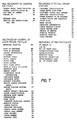
- a universal ID code dictionary is illustrated in Fig. 7.
- the dictionary of Fig. 7 is implemented as a set of microcodes stored in a read only memory 700 connected to the microprocessor of Fig. 2.
- the read only memory 700 of Fig. 7 defines a two-character ID code for each parameter which may be recorded.
- the ID codes start at AA and end at HI, as just one possible example.
- Fig. 7 depicts each ID code' as being associated with the name of a particular parameter, in practice each ID code would be associated with the buffer or memory location of that parameter in the recording system so as to identify the corresponding data in terms of its location prior to being recorded.
- a system designer may use Fig. 7, for example, to construct the actual machine language content of the read only memory 700, depending upon the particular system design employed.
- the binary bits recorded for each alphanumeric symbol representing a particular piece of information (e.g. scene luminance or customer address) or for one of the two-character ID codes of Fig. 7 are defined in accordance with the table of Fig. 8.
- the table of Fig. 8 is represented as a set of microcodes stored in a read only memory 800 connected to the microprocessor of 215. Each alphanumeric symbol is represented by a pattern of six binary bits.
- the read only memory 800 defines a universal symbol dictionary which is used to perform reading and writing of data on the film at all stages of film use.
- the table of Fig. 8 is derived from the ASCII standard symbols.
- the read only memory 800 also defines the six-bit patterns which are reserved for control purposes and which therefore may not be used for information or data. These reserved symbols are set forth in the exemplary table of Fig. 9, and include the control symbols illustrated in Fig. 6, including the start symbol 615a,b, the ID sentinel 620, a frame stop symbol 640a,b and the compliments of the start and stop sentinels 615 and 640. Other symbols are reserved in Fig. 9 in order to permit the skilled system designer to exercise other read or write controls as desired.
- each data field ends with a six-bit parity character as shown.
- the first (most significant) two bits of the parity character are always 10, to prevent the parity character from assuming the value of any of the reserved characters of Fig. 9.
- the next bit is reserved for unforeseen purposes.
- the last (least significant) these bits provide single bit parity check for (a) the ID code of the field, (b) the remaining data characters in the field, and (c) the parity character itself, respectively,
- This format preserves the six-bit-per-byte boundary, even for the parity bits, thus simplifying the task of reading recorded data. It imposes far less overhead than the well-known technique of including one parity bit per character.
- the microprocessor 215 in the camera 200 while referring to the read only memory 240 for the track locations of the various allowed parameters, must also refer to read only memories ? 00 and 800 for the universal ID code dictionary and universal symbol dictionary in order that subsequent readers of the data recorded by the camera 200 may properly interpret the data.
- the camera of Fig. 2 can always detect the film frame (position) of the next unexposed frame by simply searching for the ID sentinel " ⁇ " at the beginning of any camera track.
- the camera's processor 215 of Fig. 2 is programmed with instructions to do just that each time a film cartridge is loaded.
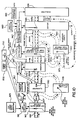
- Fig. 10 illustrates one example of the use of the dedicated film tracks (of either Fig. 1 or Fig. 3) for magnetic reading and writing in a photofinishing system.
- a photofinishing system employs its own version of the read only memories 240, 700, 800 for track location, an ID code dictionary and a symbol dictionary.
- the film strip 100 is removed from the cartridge (or at least partially extracted to expose its leader--frame 0) at an order entry station 910.
- the order entry station 910 may be located either at the dealer or at the photo-finishing laboratory.
- the order entry station has a magnetic read/write system including a head 910a and a controller (microprocessor) 915 which executes an order entry algorithm stored in memory 925.
- This algorithm defines the correct track locations in frame 0 for the recording of customer-related information, including the number of prints desired, the customer's name and address, etc., entered in at a terminal 920 or read directly from one of the camera tracks.
- a developer 927 develops the film strip 100 to form a negative image in each exposed frame.
- the film strip 100 then enters a classifier 930 which determines the optimum print exposure condition for each frame on the film strip 100.
- the classifier may do this either manually under control of a human operator or automatically using an image sensor such as is done in the Eastman Kodak 3510 Color Printer or in the Eastman Kodak CLAS 35 Color Printer.
- An exemplary manual control terminal included in the manual version of the classifier 930 is illustrated in Fig. 11.
- the luminance value at which the photosensitive print paper is to be exposed through a given negative image may be changed from a nominal value (gray level) by arbitrary values -4 to +4 by pressing one of the appropriate buttons in the row of buttons labelled "D" on the left side of the terminal of Fig. 11.
- the intensity of red, green and blue light at which the print paper is exposed may be altered from pre-defined nominal values in similar manner by arbitrary values -4 to +4 by pushing the appropriate buttons in the corresponding one of the rows of buttons labelled "R", "G” and "B", respectively.
- the resulting classification (defined by the luminance, red, green and blue print exposure values) is recorded by the classifier's magnetic head 930a in the appropriate one of the dedicated tracks (in accordance with the track allocation defined in a read only memory such as the memory 240 of Fig. 5).
- a printer 940 receives the film strip 100, reads the classification previously recorded in each frame by the classifier 930, and exposes one frame in a roll of photosensitive paper 937 through the corresponding negative frame with an exposure whose characteristics meet the recorded classification.
- the printer 940 includes its own magnetic read/write system, such as a magnetic head 940a, a controller 945 and a memory 950 storing a classifier/printer algorithm.
- This algorithm governs the magnetic reading and writing by the printer 940 and classifier 930 in accordance with the dedicated tracks format of Fig 1 or Fig. 3.
- the printer/classifier algorithm requires the controller 945 to determine whether camera tracks (tracks C0 through C3) were previously recorded on the film strip 100. If so, the dedicated track film format of Fig.
- scene-related information (if used by the classifier 930 to enhance the accuracy of the classification operation) may be found by reading the appropriate track.
- the printer/classifier algorithm in the memory 950 tells the printer 940 where to find the classification value recorded in each frame by the classifier 930.
- An operator at an inspection station views each of the prints on the print roll 943 to determine whether a makeover print is required for any of them.
- a controller 965 which executes an inspection algorithm stored in a memory 970, data is recorded on the film strip 100 in the appropriate track by the inspection station's magnetic head 960a reflecting the necessity (if any) of a makeover print in a given frame.
- the makeover was necessitated by an incorrect classification, and a correction to the original classification must be computed and recorded in the appropriate track on the film strip 100.
- this is done by the inspection station 960 itself, while in another embodiment this is done at a separate re-classifier 975 having its own magnetic recording head 975a and recording system for this purpose.
- the makeover printer 980 has its own magnetic read/write system, including magnetic head 980a, with which it may read the appropriate data in the appropriate tracks to determine which of the frames require makeover prints and, for each one of these, what the original classification value was and what the classification correction is. From this information, the makeover printer exposes the appropriate frames on the film strip 100 using the corrected classification values.
- a roll of makeover prints 983 produced by the makeover printer 980, the roll of prints 943 produced by the printer 940 and the roll of developed film including the film strip 100 are all fed to a sorter 985.
- the sorter collates the individual original and makeover prints with the corresponding film strips into complete customer orders, discarding any original prints whenever corresponding makeover prints have been made. Whether a corresponding makeover print has been made is determined by the sorter 985 through its magnetic read/write system including a controller 987 which executes a sorter algorithm stored in a memory 990 and the sorter's magnetic head 985a.
- the head 985a is simply directed to read the required data from the appropriate one of the dedicated tracks on the film strip 100 by the controller 987, in accordance with the track allocation illustrated in Fig. 5.
- Magnetically reading and writing data in a plurality of parallel magnetic tracks is a known technique in the field of magnetic tape recording and magnetic disk recording.
- One way is to use an array of stationary magnetic heads, one head for each track.
- Such an array is sold by Spin Physics, San Diego, California, as part number 203454.
Abstract
Description
- Communication between the camera user and the dealer or photofinisher typically requires written forms which are filled out by the user, usually well after a given scene has been photographed. Thus, in addition to the inconvenience of filling out such a form, scene-related information is typically lost or forgotten. Such information may include the user's desire to not have a particular frame printed or to have several prints made from a given frame, for example. Such information may also include the photographic parameters of the scene, observed by the user or by a sensor, which would have aided the photofinisher's classification of the scene to increase the quality of the prints made from the film.
- Several factors reduce the efficiency of the overall photofinishing process. For example, in a large photofinishing laboratory not operating on a 24 hour per day basis, the film processing equipment must lie dormant for a period of time at the beginning of each work day until enough incoming customer film has been sorted to form one batch of a minimum number (e.g. 70) of film strips of the same type (such as color negative 35 mm film) to justify running the printing equipment. Of course, undeveloped film (regular customer orders) must be separated from developed film (print re-orders).
- More significant sources of inefficiency in the photofinishing process include the mechanical steps required to maintain proper correspondence between each film strip and the prints made from it, as well as the customer's identity. These mechanical steps include the sorting and handling of each form or envelope originally filled out by the customer so that the envelope follows the customer's film strip throughout the photofinishing process and winds up with the corresponding set of prints.
- One of the most significant sources of inefficiency in the photofinishing process arises from the necessity of re-printing an image from a particular frame on a customer's film strip whenever inspection reveals that the corresponding original print was incorrectly made (usually by an incorrect exposure of the photosensitive print paper to the developed film negative image). In order to replace the original print with a better (so-called "makeover") print, the exposure conditions ("classification") used to make the original print from the negative film image must first be corrected. Somehow, the particular film negative frame in question must be re-classified and then re-printed while preserving the original prints of the other frames. The mechanical steps include notching the prints to indicate the boundaries between adjacent prints and between adjacent orders on a roll of prints as well as marking any original print requiring a makeover in a labor intensive procedure which ensures that proper correspondence between each film strip and the corresponding original prints, makeover prints and customer order form (envelope) is never lost.
- Recording of information on the film has been loosely suggested as one possible way around some of the limitations described above. These suggestions have ranged from optical recording of eye-readable symbols or machine readable symbols to the magnetic recording of machine readable data. Of course, optical recording on the film has only limited use, because once the film has been developed, no further recording may be done. Furthermore, the information must be restricted to those limited areas on the film not occupied by the camera-exposed image of each frame, a significant limitation on the amount of information that can be recorded.
- An article entitled "Technical Experience with DATAKODE MAGNETIC CONTROL SURFACE / Revised Edition", Eastman Kodak Company, 1984, Publication No. V3-517 discloses the use of a functionally transparent magnetic layer on a motion picture film strip especially for recording or reading time and control codes by an equipment, wherein the film strip may be transported at different velocities and in different directions. The magnetic layer has one longitudinal track beginning and ending within a frame of the film strip, which track is magnetically recorded in this magnetic layer and wherein the track comprises self-clocking encoded data having start /stop sentinels. The direction of film travel is determined by signals from an interrupter wheel of a synchronizer of the equipment for synchronizing pictures with sound on the film strip.
- With magnetic recording in a virtually transparent magnetic layer, high density recording may be done everywhere on the film including in the image area, so that all relevant information theoretically could be recorded with each frame on the film. However, what has not been recognized in the prior art is that complete exploitation of the potential capabilities of magnetic recording on film results in an unwieldy mass of data being recorded on the film, various bits of which must be separately accessed at various stages of the film use by camera and photofinisher. In such a scenario, the photofinisher in particular must find a certain needle of data in a massive haystack of data at a given step in the photofinishing process.
- A problem underlying all of the foregoing is that neither the camera nor any particular stage of the photofinisher may be relied upon to transport the film at some pre-defined velocity while data is being recorded or read, nor even at a uniform velocity. Thus, an awkward requirement could arise that clocking or velocity information be recorded in a separate track each time data is recorded in one of the dedicated tracks. Such a requirement would complicate the recording process, making it less reliable, and reduce the area on the film available for recording information.
- Another problem is how to provide the photofinisher with an automatic indication whenever a particular film strip has been spliced in a roll of film strips but rotated (either end-for-end or emulsion side up) with respect to its original orientation (as established during data recording in the camera or at an order entry station).
- Another problem arises if the accommodation of magnetic reading/writing on the film by both the camera and the various dealer and photofinishing stages precludes the photofinisher from reading/ writing on film formats (e.g. 110 or 126 film) adapted to ordinary cameras not having magnetic read/write capability. The problem here is how to permit the photofinisher to use magnetic recording on film without regard to the format of the film or the type of camera used, using the same magnetic recording format and hardware for all cases. Solving this last problem would permit all film for all cameras to include the additional magnetic layer, for photofinishing with the same magnetic read/write format and automated protocols using the film magnetic layer as a frame-by-frame scratch pad memory.
- According to the present invention, there is provided a film strip and a data communication apparatus for processing a film strip as defined in
Claims - Essentially, magnetic reading and writing of information in a virtually transparent magnetic layer in the film during each stage of film used and film processing is restricted to certain dedicated parallel tracks extending longitudinally along the length of the film, the choice of track being determined in accordance with the particular information being recorded. Magnetic reading/writing is performed with transport of the film by the camera during field use and during transport of the film by the dealer or photofinisher during film processing, printing, etc. The tracks are dedicated by universal pre-arrangement to certain sets of parameters or information, each set being of particular interest to a certain stage in the use of the film, the various stages including the camera, the dealer order entry station, the photofinisher order entry station, the classifier, the printer, the inspection or re-classifier station and the enveloper-sorter station.
- The photofinisher tracks occupy the principal image area of each frame, so as to maximize the number of tracks available to the photofinisher and to render the format of these tracks virtually immune to any differences between various film formats or film perforation patterns. The photofinisher tracks therefore have a universally applicable format for use not just in photofinishing but also in film-to-video players, electronic print processing, etc.
- The camera tracks are present only in film adapted for use in cameras having magnetic read/write capability. For this purpose, the camera tracks are accommodated along the film edges, without impacting the photofinisher track locations, by interruption of the usual film perforation pattern along the film edges. In the preferred embodiment, each perforation is located next to the image area while the camera tracks are located next to the image area along the film edges between successive perforations.
- All data is magnetically recorded on the film using a novel self-clocking code which is completely self-clocking, in order to provide automatic data synchronization between the various users without requiring any of them to transport the film at the same speed or even at a uniform speed when reading and writing. The self-clocking code is a single channel comprising a succession of uniform clocking pulses with intervening data transition pulses. The temporal placement of each data transition pulse relative only to the two clocking pulses which immediately preceed it and follow it, respectively, determines whether that transition pulse corresponds to a binary one or zero. Thus, film transport velocity changes between the recording of successive binary bits have no effect upon the information content of the self-clocking encoded data. More importantly, differences in film transport velocity between data recording and data playback have no effect upon the readability of the self-clocking encoded data.
- In a preferred embodiment of the invention, the various types of information are allocated among the dedicated tracks in accordance with groups of related information types or parameters, some individual groups being used by more than one stage of the film use cycle. Furthermore, in this preferred embodiment, information common to all frames of the film is in dedicated tracks on the film leader. Specifically, information common to all frames, such as film type, camera type, owner identification, a directory of written information and the like are recorded in a first camera track (near one film edge) on the film leader. This first camera track is designated track C0 while the film leader is designated
frame 0. Scene related parameters automatically sensed by the camera (such as scene luminance, camera orientation, color temperature, flash fire, etc.) are recorded in track C0 in each subsequent frame (e.g. frames 1-25). A second camera track, track C1, is dedicated to the recording of secondary information, such as shutter speed, aperture size, etc. Clearly, an intelligent photofinishing classifier station, in attempting to compute the optimum exposure conditions to make a print, would read the data on track C0 in each offrames 1 through 24 (for example), while a finishing station, in attempting to maintain correspondence between a customer's film and his order form or envelope, would read the data on track C0 inframe 0. A similar sort of allocation of photofinisher dedicated tracks is employed, with customer print order request data being recorded in a first photofinisher track (F0) inframe 0, process data such as image classification and number of prints made by frame in track F01, frames 1-25 (for example). Any makeover correction is recorded in track F02. A summary of makeover data (e.g. total number of makeover prints) is recorded in track F2 inframe 0. Other photofinisher tracks may be dedicated to uses other than photofinishing, such as frame-by-frame user instructions for film-to-video players or the like. - The invention solves the problem of attaining data synchronization at all stages of film use without requiring that each stage transport the film at constant velocity nor even at the same velocity while recording or playing back data. The invention achieves this without requiring the recording of an extra space-wasting clocking track simultaneously with the data track. Instead, the representation of the binary state of a particular bit is unaffected by the film transport speed during recording and playback and is self-clocking. This representation uniquely depends upon the temporal relationship between each data transition pulse and its immediately preceeding and succeeding clock pulses in the serial pulse train comprising the self-clocking code. In the preferred embodiment, a one bit is represented by a data transition pulse which is closer to the preceeding clock pulse. For a zero bit, the data transition pulse is closer to the succeeding clock pulse.
- The invention solves the data access problem faced by (among others) the photofinisher of "finding a needle in a haystack" because each stage need merely know which track has been dedicated to the data relevant to that stage, and may read the data from that track while ignoring all other data magnetically recorded on the film. Furthermore, in some cases the reading of data can be dispensed with entirely in order to make certain basic determinations about the film, by simply determining whether certain tracks are empty or not. For example, whether a particular strip of film has already been developed (and therefore was submitted for print re-order) is readily determined by seeing whether or not certain tracks (e.g. track F1 of frames 1 - 24) contain recorded data or not.
- The invention may be understood by reference to the accompanying drawings, of which:
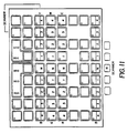
- Fig. 1 is a diagram illustrating the parallel dedicated tracks in a virtually transparent magnetic layer on film having a special perforation format particularly adapted for use in cameras having a magnetic film read/write capability;
- Fig. 2 is a simplified diagram illustrating the concept of a camera adapted to read or write data on the film of Fig. 1;
- Fig. 3 is a diagram illustrating the parallel dedicated tracks in a virtually transparent magnetic layer on film having the currently ubiquitous perforation format used in ordinary cameras not having a magnetic film read/write capability;
- Fig. 4 is a diagram illustrating the accommodation of film wander in the camera of Fig. 2 by the use of different head widths at the various stages of film use;
- Fig. 5 is a block diagram illustrating the architecture of a read only memory containing a directory of track locations for various parameters which may be magnetically written or read on the film, in accordance with the dedicated track format of Fig. 1;
- Fig. 6 is a diagram illustrating the preferred data format used in the dedicated tracks of Fig. 1 or Fig. 3;
- Fig. 7 illustrates an exemplary data identification code table for universal use with the data format of Fig. 6 by all stages of film use including camera and photofinisher;
- Fig. 8 illustrates an exemplary symbol table for universal use with the data format of Fig. 6 by all stages of film use including camera and photofinisher;
- Fig. 9 illustrates an exemplary reserved control symbol table for universal use with the data format of Fig. 6 by all stages of film use including camera and photofinisher;
- Fig. 10 is a block diagram illustrating a photofinishing system having magnetic read/write hardware including automated protocols which use the film of Figs. 1 or 3 as a scratch pad memory for increased efficiency or performance;
- Fig. 11 illustrates a typical operator's keyboard used in the photofinishing system of Fig. 10 to classify developed negatives for correct print exposures;
- Figs. 12a and 12b illustrate the form of the self-clocking code used in the invention;
- Fig. 13 illustrates the use of each start and stop sentinel character and its compliment to facilitate film reversal sensing;
- Figs. 14a and 14b illustrate the type of film reversal which is best detected using the invention; and
- Fig. 15 is a simplified block diagram illustrating a self-clocking encoding/decoding on-film magnetic recording system.
- Referring to Fig. 1, a
strip 100 of color negative film 35 millimeters wide includes abase 110, various well-known photo-chemical layers 115 on one side of thebase 110 and a virtually transparent magnetic layer 120 on the other side. An anti-static andlubricating layer 122 overlies the magnetic layer 120. Thefilm strip 100 includesperforations 125 spaced along the film edge at regular intervals matching the pitch of a metering pawl in a camera adapted to use thefilm strip 100. - For purposes of recording data in the magnetic layer 120, each frame of the
film strip 100 is divided into a plurality of predetermined parallel longitudinal track locations where magnetic tracks of data may be recorded. Each of the tracks is preferably labeled as shown in Fig. 1. In particular, the two outermost tracks along each edge of thefilm strip 100 are tracks C0, C1 and tracks C2, C3, respectively. The thirty innermost tracks are tracks F00 through F29. Each one of the outermost tracks C0 through C3 is dedicated to the recording of a particular type of information by a camera having magnetic recording capability, in accordance with a pre-arrangement universally established for all cameras and photofinishers. In a similar manner, each one of the innermost tracks is dedicated to the recording of a particular type of information by a particular type of photofinishing (or other) equipment, in accordance with the above-referenced universal pre-arrangement. - In order to accommodate the presence of the camera tracks C0 through C3 along the film strip edges, the
perforations 125 are excluded from periodicimperforate edge regions 100a adjacent each exposed frame and are restricted tointermediate regions 100b lying between subsequent frames. In the embodiment of Fig. 1, there is only one perforation in eachintermediate region 100b. In the preferred embodiment, the perforations lie along only one longitudinal edge of thefilm strip 100. - Referring to Fig. 2, a
camera 200 transports thefilm strip 100 between thereels 205a,b, of a film cartridge and a take-up sprocket, respectively, conforming to the format of theperforations 125 of Fig. 1. Thecamera 200 includes a magnetic read/write head 210 in near proximity with the magnetic layer 120 on the unsensitized side of thefilm strip 100. Amicroprocessor 215 controls magnetic data recording or playback by thehead 210 throughhead electronics 220. - The
microprocessor 215 may accept order information to be magnetically recorded on thefilm strip 100 from the camera user through camera controls 225, such information pertaining to the number of prints desired for a given frame, by frame number, for example, or the name and address of the camera user for ultimate use by the photofinisher. Themicroprocessor 215 may also accept scene related information fromscene sensors 230 to be magnetically recorded on thefilm strip 100 for ultimate use by the photofinisher. Such information may include camera orientation, scene luminance and the like. - Using the dedicated track on film format of Fig. 1, data is recorded by either a camera, an order entry station, the photofinisher or any other stage of film use, by converting the data into binary bits and then encoding the binary data using a unique self-clocking code. Such self-clocking encoding is performed in accordance with the teachings of
European Patent Application 0 396 775 which claims the priority of U.S. Patent Application Serial Number 206,646 filed June 14, 1988 by Michael Wash entitled "Method for Modulating a Binary Data Stream" and assigned to the assignee of the present Application, the disclosure of which is incorporated herein by reference. - The self-clocking code described in the referenced patent application is briefly summarized here with reference to Fig. 12 of the accompanying drawings. The code comprises a serial stream of pulse edge transitions of a first type (e.g. positive-going edge transitions) and those of a second type (e.g. negative-going edge transitions) in alternating sequence. The first type pulse transitions serve as clock indicators while the second type serve as binary data indicators. A binary one is indicated in Fig 12a by a second
type pulse transition 1215 which is temporally closer to the immediately preceeding firsttype pulse transition 1205 and farther from the succeeding firsttype pulse transition 1210. A binary zero is indicated in Fig. 12b by a secondtype pulse transition 1215′ temporally closer to the succeeding firsttype pulse transition 1210 than to the preceeding one. With this novel self-clocking code, film transport velocity can vary during recording and playback without affecting the ability to synchronize and read the recorded data. Thus, the camera of Fig. 2 may record data while winding the film between exposures without imposing any velocity controls or recording an independent clock track. - The self-clocking code of Fig. 12 facilitates the automatic detection of film reversal. For this purpose, two six-bit characters from the table of reserved characters of Fig. 9 are chosen as the start and stop sentinels, respectively, recorded at the beginning and end of each frame in each dedicated track, in a manner described herein with reference to Fig. 6. Furthermore, the compliments of the two symbols thus chosen are also reserved, as indicated in Fig. 13, the latter two reserved symbols comprising a film-reversed start sentinel and a film-reversed stop sentinel. This arrangement exploits a property of the self-clocking code of Fig. 12 in which self-clocking data played back backwards (by transporting the film past the head in the direction opposite from that in which it was transported earlier during recording) results in its complement being decoded.
- Thus, if the film image of Fig. 14a corresponds to the orientation of the film during the magnetic recording of data on the film by the camera for example, and if Fig. 14b corresponds to the orientation of the film as it is spliced and loaded into photofinishing equipment having magnetic read/write capability, the film reversed stop sentinel will be detected, followed by the film reversed start sentinel, with every frame of data. Such film-reversed start and stop sentinels serve as flags to notify the photofinisher that the film has been rotated as indicated in Fig. 14b. If the film has been turned inside out instead, the technique of Fig. 13 does not create a flag. However, such an error is easily detected, since it causes the opposite side of the film to face the photofinisher's magnetic heads, thus increasing the distance between the heads and the magnetic layer 120 of Fig. 1, resulting in a decrease in signal-to-noise ratio.
- Fig. 15 illustrates a simple example of a magnetics on film self-clocking read/write system useful in the
camera 200 of Fig. 2. - The advantage of the longitudinal dedicated track format of Fig. 1 is that magnetic recording of data on the
film strip 100 may be performed by the camera using a relatively stationary head (i.e. the head 210) by buffering all of the data to be recorded in a particular frame in a particular camera track and then transmitting the data to the head just as the film is being wound to the next frame. - The
microprocessor 215 includes a read onlymemory 240 containing instructions sufficient to ensure that each type of information received is recorded in the correct one of the dedicated camera tracks C0 - C3 in accordance with a universal pre-arrangement common to both the camera and the photofinisher. For this purpose, the microprocessor sorts and buffers each piece of information in compliance with the instructions stored in the read onlymemory 240. The nature of this pre-arrangement and the architecture of the read only memory will be described below in this specification. - The format of the photofinisher tracks F00 through F29 is the same regardless of the placement of the
film perforations 125 of Fig. 1. Thus, a photofinisher may employ the same magnetic recording protocols and hardware on all types of film provided that a virtually transparent magnetic layer (such as the layer 120 of Fig. 1) is added to all types of film. Thus, referring to Fig. 3, ordinary 35 mm color negative film having the now-standard pattern of closely spaced perforations along both film edges accommodates the photofinisher tracks F00 through F29 having the same width and spacing as that of the special film format of Fig. 1. Although the perforations of Fig. 3 preclude the presence of the camera tracks C0 through C3, such film is not used in cameras having magnetic read/write capabilities and so the camera tracks need not be present. The advantage here is that all subsequent users of the film (i.e. photofinisher, film-to-video player, etc.) have been allocated the maximum number of tracks for all film formats, including those of Fig. 1 and of Fig. 3. - Referring to Fig. 4, the width of the camera dedicated tracks C0 - C3 is greater than that of the photofinisher tracks F00 - F29. Of course, these track widths are controlled by the selection of the camera head widths and the photofinisher head widths. Preferably, the difference is sufficient to accommodate film wander in the camera during winding of the film while recording is performed by the
head 210. Such wandering causes the camera tracks to have the meandering appearance illustrated in Fig. 4. Note in Fig. 4 that the photofinisher head, which must read the camera tracks, does not leave the camera track because it has a much smaller width. - Fig. 5 illustrates the allocation of the dedicated tracks, among the various information types, implemented by microcodes stored in the read only
memory 240 of Fig. 2. There are four camera tracks and fifteen photofinisher tracks in each frame of the film exposed by the camera, these frames being designatedframes 1 through 25. The film leader and trailer are designatedframes 0 and 26, respectively. In general, the information recorded inframes 0 and 26 pertains to thefilm strip 100 as a whole, while the information recorded in each offrames 1 through 25 is unique for a particular frame. In Fig. 5, three of the four camera tracks are used by the camera, while three of the thirty photofinisher tracks are used by the photofinisher. The rest of the photofinisher tracks are reserved for the recording of film-to-video player instructions (track F03), electronic print processing instructions (track F04) and audio (track F05 through F14). The remaining tracks (F15 - F29) are reserved for unforeseen purposes. - Each of the tracks is dedicated to a particular group of information types which would in most cases be written or read together. Thus,
frame 0 track C0 is reserved for information relating to the owner and the camera for recording by the camera. Similarly,frame 0 track F00 is reserved for information relating to the owner and the photofinisher for recording by the photofinisher. Likewise, track F00 offrame 0 is reserved for recording by the photofinisher--or by an order entry station--of the customer's instructions, the film type, and related information pertaining to the treatment of the order. Track F02 offrame 0 is reserved for the recording of historical information regarding the location of frames requiring makeover prints and print reorders by the customer, for use by the photofinisher during a subsequent print reorder by the customer. - Track C0 of each exposed frame (frames 1-25) is reserved for scene-related information for recording by the camera, such as scene luminance, camera orientation and the like. Similarly, track F01 is reserved for photofinisher information unique to a particular exposed frame such as the classification of the negative image (determination of the proper print exposure), number of prints made, etc. Any makeover correction to the classification is recorded in track F02.
- The embodiment of Fig. 5 does not take into account all of the information types which may be magnetically recorded by the camera, retail order station or photofinisher on the film. However, the embodiment of Fig. 5 is an example of the manner in which all information types may be classified as to which track each one is to be assigned. The principle underlying the manner in which each information type is assigned to a particular track is that all information related to a particular transaction should be recorded on the same track, so that that track is dedicated to being written or read during those operations associated with that transaction.
- The various transactions provided for in the embodiment of Fig. 5 are: (a) recording of customer data, including the customer address; (b) recording of scene-related information with each exposure, including parameters characterizing lighting conditions and camera exposure settings; (c) recording by the retail order station or photofinisher of customer order information, such as the number of prints desired; (d) the recording of inspection and makeover classification correction for a given frame by the photofinisher; (e) the recording of a summary of makeover data or print reorder data applicable to the entire film roll; (f) the recording of instructions for a film to video player; (g) the recording of instructions for electronic print processing; and (h) the recording of audio. In general (but not always) each of the magnetic recording tracks illustrated in Fig. 1 is dedicated to one of the foregoing transactions (a) through (h). The result is that during recording the amount of searching for an available recording location is minimized while during playback the amount of searching through data irrelevant for a particular operation is also minimized. For example, during the classification operation, in which the optimum print exposure condition for each frame is determined, all scene-related information potentially helpful in determining the proper classification may be obtained by reading data from a single track, namely the camera-dedicated track C0 in each exposed frame (frames 1-25). No other track need be read.
- As previously described herein with respect to Fig. 1, the data recorded magnetically on the
film strip 100 is divided into frames exposed by the camera (frames 1-25) as well as the film leader (frame 0), the data within each frame being allocated among a plurality of dedicated tracks within the frame. Fig. 6 illustrates the preferred data format within each track of each frame. - In Fig. 6, each
track 600 has the length of one frame and is divided into a plurality offields 610. Eachtrack 600 includes apredicate start sentinel 615 at its beginning end (the left-hand edge of the track in Fig. 6 where the head begins its scanning of the track 600) and astop sentinel 640 at its end. Each field includes a predicate ID sentinel 620 followed immediately by anID code 625. The purpose of thetrack start sentinel 615 is to notify the read/write system in the camera or in the photofinishing hardware of the beginning location of thetrack 600. The purpose of the field ID sentinel 620 is to notify the same system of the beginning location of each succeeding field in thetrack 600. The purpose of theID code 625 is to identify the type of information recorded in the following field. In the preferred embodiment of the invention, eachstart sentinel 615 is preceeded by a start sync mark 616 and eachend sentinel 640 is followed by a stop sync mark 641. The marks 616, 641 enable special circuitry to achieve proper synchronization under adverse conditions described therein. - The ID code is recorded in the beginning of each field and is determined by the information type which follows it. For example, if the
camera 200 of Fig. 2 is about to record the level of scene luminance observed by sensors on the camera during exposure of the frame, the camera first causes a unique ID code to be recorded just ahead of the data representing the scene luminance level. In the simplest embodiment, a unique ID code is assigned to each parameter or information type which may be recorded on the film, so that the ID codes for all possible information types constitute a large dictionary. Inasmuch as the same dictionary must be employed by all stages in the life cycle of the film (e.g., camera, photofinisher, etc.), identical read only memories are provided at each stage, each of these memories embodying a universal ID code dictionary and controlling the reading and writing of ID codes at each stage of film use. - The advantage is that the placement of a particular parameter within the
track 600 by the camera need not be previously known by the photofinisher in order for the photofinisher to be able to find that parameter on the track, since the photofinisher may simply refer to the corresponding ID code recorded by the camera. This same advantage holds between any other separate components, where one component writes data onto the film and the other independently reads the data from the film at a later time and, typically, at a different location. - One exemplary embodiment of a universal ID code dictionary is illustrated in Fig. 7. The dictionary of Fig. 7 is implemented as a set of microcodes stored in a read only
memory 700 connected to the microprocessor of Fig. 2. The read onlymemory 700 of Fig. 7 defines a two-character ID code for each parameter which may be recorded. In this embodiment, the ID codes start at AA and end at HI, as just one possible example. While Fig. 7 depicts each ID code' as being associated with the name of a particular parameter, in practice each ID code would be associated with the buffer or memory location of that parameter in the recording system so as to identify the corresponding data in terms of its location prior to being recorded. A system designer may use Fig. 7, for example, to construct the actual machine language content of the read onlymemory 700, depending upon the particular system design employed. - The binary bits recorded for each alphanumeric symbol representing a particular piece of information (e.g. scene luminance or customer address) or for one of the two-character ID codes of Fig. 7 are defined in accordance with the table of Fig. 8. The table of Fig. 8 is represented as a set of microcodes stored in a read only
memory 800 connected to the microprocessor of 215. Each alphanumeric symbol is represented by a pattern of six binary bits. The read onlymemory 800 defines a universal symbol dictionary which is used to perform reading and writing of data on the film at all stages of film use. The table of Fig. 8 is derived from the ASCII standard symbols. - The read only
memory 800 also defines the six-bit patterns which are reserved for control purposes and which therefore may not be used for information or data. These reserved symbols are set forth in the exemplary table of Fig. 9, and include the control symbols illustrated in Fig. 6, including the start symbol 615a,b, the ID sentinel 620, a frame stop symbol 640a,b and the compliments of the start and stopsentinels - Referring again to Fig. 6, each data field ends with a six-bit parity character as shown. The first (most significant) two bits of the parity character are always 10, to prevent the parity character from assuming the value of any of the reserved characters of Fig. 9. The next bit is reserved for unforeseen purposes. The last (least significant) these bits provide single bit parity check for (a) the ID code of the field, (b) the remaining data characters in the field, and (c) the parity character itself, respectively, This format preserves the six-bit-per-byte boundary, even for the parity bits, thus simplifying the task of reading recorded data. It imposes far less overhead than the well-known technique of including one parity bit per character.
- In Fig. 2, the
microprocessor 215 in thecamera 200, while referring to the read onlymemory 240 for the track locations of the various allowed parameters, must also refer to read only memories ?00 and 800 for the universal ID code dictionary and universal symbol dictionary in order that subsequent readers of the data recorded by thecamera 200 may properly interpret the data. - Referring to Fig. 9, by reserving the six-bit character "[" as the ID sentinel 620 used by the film manufacturer only and "<" as the ID sentinel for all other users (camera, photofinisher, etc.), the camera of Fig. 2 can always detect the film frame (position) of the next unexposed frame by simply searching for the ID sentinel "<" at the beginning of any camera track. Preferably, the camera's
processor 215 of Fig. 2 is programmed with instructions to do just that each time a film cartridge is loaded. - Use of the dedicated film tracks for magnetic recording of information by a camera has been described with reference to the example of Fig. 2. Fig. 10 illustrates one example of the use of the dedicated film tracks (of either Fig. 1 or Fig. 3) for magnetic reading and writing in a photofinishing system. In general, such a photofinishing system employs its own version of the read only
memories - In Fig. 10, the
film strip 100 is removed from the cartridge (or at least partially extracted to expose its leader--frame 0) at anorder entry station 910. Theorder entry station 910 may be located either at the dealer or at the photo-finishing laboratory. The order entry station has a magnetic read/write system including ahead 910a and a controller (microprocessor) 915 which executes an order entry algorithm stored inmemory 925. This algorithm defines the correct track locations inframe 0 for the recording of customer-related information, including the number of prints desired, the customer's name and address, etc., entered in at a terminal 920 or read directly from one of the camera tracks. Adeveloper 927 develops thefilm strip 100 to form a negative image in each exposed frame. - The
film strip 100 then enters aclassifier 930 which determines the optimum print exposure condition for each frame on thefilm strip 100. The classifier may do this either manually under control of a human operator or automatically using an image sensor such as is done in the Eastman Kodak 3510 Color Printer or in the Eastman Kodak CLAS 35 Color Printer. An exemplary manual control terminal included in the manual version of theclassifier 930 is illustrated in Fig. 11. The luminance value at which the photosensitive print paper is to be exposed through a given negative image may be changed from a nominal value (gray level) by arbitrary values -4 to +4 by pressing one of the appropriate buttons in the row of buttons labelled "D" on the left side of the terminal of Fig. 11. The intensity of red, green and blue light at which the print paper is exposed may be altered from pre-defined nominal values in similar manner by arbitrary values -4 to +4 by pushing the appropriate buttons in the corresponding one of the rows of buttons labelled "R", "G" and "B", respectively. The resulting classification (defined by the luminance, red, green and blue print exposure values) is recorded by the classifier's magnetic head 930a in the appropriate one of the dedicated tracks (in accordance with the track allocation defined in a read only memory such as thememory 240 of Fig. 5). - It should be noted that if data previously recorded on the
film strip 100 indicates that it has been previously developed and printed (so that a classification value is stored in each frame in the appropriate track), then thedeveloper 927 and theclassifier 930 are automatically bypassed. - A
printer 940 receives thefilm strip 100, reads the classification previously recorded in each frame by theclassifier 930, and exposes one frame in a roll of photosensitive paper 937 through the corresponding negative frame with an exposure whose characteristics meet the recorded classification. Theprinter 940 includes its own magnetic read/write system, such as a magnetic head 940a, acontroller 945 and amemory 950 storing a classifier/printer algorithm. This algorithm governs the magnetic reading and writing by theprinter 940 andclassifier 930 in accordance with the dedicated tracks format of Fig 1 or Fig. 3. For example, the printer/classifier algorithm requires thecontroller 945 to determine whether camera tracks (tracks C0 through C3) were previously recorded on thefilm strip 100. If so, the dedicated track film format of Fig. 1 applies and scene-related information (if used by theclassifier 930 to enhance the accuracy of the classification operation) may be found by reading the appropriate track. Likewise, the printer/classifier algorithm in thememory 950 tells theprinter 940 where to find the classification value recorded in each frame by theclassifier 930. - An operator at an inspection station views each of the prints on the
print roll 943 to determine whether a makeover print is required for any of them. Under control of acontroller 965 which executes an inspection algorithm stored in amemory 970, data is recorded on thefilm strip 100 in the appropriate track by the inspection station's magnetic head 960a reflecting the necessity (if any) of a makeover print in a given frame. Presumably the makeover was necessitated by an incorrect classification, and a correction to the original classification must be computed and recorded in the appropriate track on thefilm strip 100. In one embodiment, this is done by theinspection station 960 itself, while in another embodiment this is done at aseparate re-classifier 975 having its ownmagnetic recording head 975a and recording system for this purpose. Thefilm strip 100--which may be included in a roll of many such film strips--is sent to amakeover printer 980, typically by transferring the entire roll. Themakeover printer 980 has its own magnetic read/write system, including magnetic head 980a, with which it may read the appropriate data in the appropriate tracks to determine which of the frames require makeover prints and, for each one of these, what the original classification value was and what the classification correction is. From this information, the makeover printer exposes the appropriate frames on thefilm strip 100 using the corrected classification values. - A roll of makeover prints 983 produced by the
makeover printer 980, the roll ofprints 943 produced by theprinter 940 and the roll of developed film including thefilm strip 100 are all fed to asorter 985. The sorter collates the individual original and makeover prints with the corresponding film strips into complete customer orders, discarding any original prints whenever corresponding makeover prints have been made. Whether a corresponding makeover print has been made is determined by thesorter 985 through its magnetic read/write system including a controller 987 which executes a sorter algorithm stored in amemory 990 and the sorter'smagnetic head 985a. Thehead 985a is simply directed to read the required data from the appropriate one of the dedicated tracks on thefilm strip 100 by the controller 987, in accordance with the track allocation illustrated in Fig. 5. - Magnetically reading and writing data in a plurality of parallel magnetic tracks is a known technique in the field of magnetic tape recording and magnetic disk recording. One way is to use an array of stationary magnetic heads, one head for each track. Such an array is sold by Spin Physics, San Diego, California, as part number 203454.
- While the invention has been described in detail by specific reference to preferred embodiments thereof, it is understood that other variations and modifications may be made without departing from the scope of the invention.
Claims (6)
- An elongate photographic film strip (100) susceptible of exposure of successive frames thereof by a camera (200) having a magnetic reading or writing system (210) and adapted for developing and printing by a photofinishing device having a magnetic reading or writing system (910a, 935a, 940a, 960a, 975a, 980a, 985a, 990a), wherein the film strip (100) may be transported at different velocities and in different directions, the film strip (100) having a magnetic layer (120) with at least one longitudinal track (600) beginning and ending within a frame, which track is magnetically recorded in said magnetic layer, and said track (600) comprising self-clocking encoded data having start /stop sentinels (615, 640);
characterized in that
said self-clocking encoded data comprise first and/or second self-clocking encoded binary characters uniquely representing track start (615) and stop (640) sentinels respectively, such that the direction of film strip (100) transport can be automatically detected through said start and/or stop sentinels by the reading systems. - The film strip (100) of Claim 1 wherein said magnetic layer (120) is virtually transparent.
- Data communication apparatus for use in a stage of a film processing system which processes an elongate photographic film strip (100) having successive frames and a magnetic layer (120); said apparatus comprising means for writing or reading self-clocking encoded data in the magnetic layer (120) on said film strip (100), said data being relegated to one or more longitudinal tracks (600) in each of said frames, and said encoded data including start /stop sentinel characters (615,640) placed at the beginning and end of the tracks (600) respectively; and means for transporting said film strip wherein the filmstrip may move past said reading means at different velocities and in different directions;
characterized in that
each sentinel character (615, 640) has a unique self-clocking encoded binary bit sequence, such that the direction of film strip transport can be automatically detected through said start and/or stop sentinel characters by the reading means. - The apparatus of Claim 3 further comprising means for sensing whether the complement of either of said binary bit sequences is read from any of said tracks (600) so as to sense if said film strip (100) is being transported in a longitudinal direction opposite to that in which said tracks (600) were previously recorded.
- The apparatus of Claim 4 wherein the stage of the film processing system comprises one of a camera (200), a dealer order entry system, a photofinisher order entry system (910), a classifier (930), a printer (940), an inspection or reclassifier station (960), and a sorter station (985).
- The apparatus of Claim 3 wherein said stage comprises a photofinishing system including means for sensing whether self-clocking encoded data has previously been recorded in said magnetic layer (120) as one or more longitudinal camera-dedicated tracks (CO-C3); and means for recording selfclocking encoded data in said magnetic layer (120) so as to create one or more photofinisher-dedicated tracks (F00-F29) in each of said frames, and for placing a said start sentinel character (615) and/or a said stop sentinel character (640) at the beginning and end, respectively of each of said photofinisherdedicated tracks.
Applications Claiming Priority (3)
| Application Number | Priority Date | Filing Date | Title |
|---|---|---|---|
| US254987 | 1988-10-07 | ||
| US07/254,987 US4977419A (en) | 1988-10-07 | 1988-10-07 | Self-clocking encoding/decoding film information exchange system using dedicated magnetic tracks on film |
| PCT/US1989/004362 WO1990004253A1 (en) | 1988-10-07 | 1989-10-04 | Self-clocking encoding/decoding film information exchange system using dedicated magnetic tracks on film |
Publications (2)
| Publication Number | Publication Date |
|---|---|
| EP0438476A1 EP0438476A1 (en) | 1991-07-31 |
| EP0438476B1 true EP0438476B1 (en) | 1995-09-20 |
Family
ID=22966359
Family Applications (1)
| Application Number | Title | Priority Date | Filing Date |
|---|---|---|---|
| EP89911663A Expired - Lifetime EP0438476B1 (en) | 1988-10-07 | 1989-10-04 | Self-clocking encoding/decoding film information exchange system using dedicated magnetic tracks on film |
Country Status (11)
| Country | Link |
|---|---|
| US (1) | US4977419A (en) |
| EP (1) | EP0438476B1 (en) |
| JP (1) | JP2911155B2 (en) |
| KR (1) | KR0139099B1 (en) |
| CN (1) | CN1025373C (en) |
| AU (1) | AU629255B2 (en) |
| BR (1) | BR8907693A (en) |
| CA (1) | CA1314099C (en) |
| DE (1) | DE68924352T2 (en) |
| MX (1) | MX163389B (en) |
| WO (1) | WO1990004253A1 (en) |
Families Citing this family (84)
| Publication number | Priority date | Publication date | Assignee | Title |
|---|---|---|---|---|
| US5151726A (en) * | 1987-05-09 | 1992-09-29 | Canon Kabushiki Kaisha | Camera or printer capable of automatically changing print size |
| JPH01233431A (en) * | 1988-03-15 | 1989-09-19 | Nikon Corp | Camera with used cartridge discriminating device |
| CA1340235C (en) * | 1988-10-07 | 1998-12-15 | Robert Paul Cloutier | Frame-by-frame data recording film information exchange system using dedicated magnetic tracks of film |
| US4965626A (en) * | 1988-10-07 | 1990-10-23 | Eastman Kodak Company | Printing and makeover process for magnetically encodable film with dedicated magnetic tracks |
| CA1323098C (en) * | 1988-10-07 | 1993-10-12 | Gary Lee Robison | Photofinishing apparatus with film information exchange system using dedicated magnetic tracks on film |
| US5101225A (en) * | 1988-10-07 | 1992-03-31 | Eastman Kodak Company | Film information exchange system using self-clocking encoded start and stop sentinels |
| US5085529A (en) * | 1988-10-17 | 1992-02-04 | Insignia Systems, Inc. | Thermal printing system with encoded sheet set |
| US5128711A (en) * | 1989-04-28 | 1992-07-07 | Fuji Photo Film Co., Ltd. | Apparatus for recording position information of principal image and method of detecting principal image |
| US4965628A (en) * | 1989-06-28 | 1990-10-23 | Eastman Kodak Company | Photographic film with latent image multi-field bar code and eye-readable symbols |
| US5155511A (en) * | 1990-05-29 | 1992-10-13 | Canon Kabushiki Kaisha | Camera using film with magnetic memory |
| JP2926603B2 (en) * | 1990-07-13 | 1999-07-28 | 株式会社ニコン | Camera shooting information recording device |
| US5083153A (en) * | 1990-08-17 | 1992-01-21 | Eastman Kodak Company | Film transporting apparatus |
| US5815752A (en) * | 1990-09-13 | 1998-09-29 | Canon Kabushiki Kaisha | Camera having a magnetic recording apparatus selectively operable based on film feed speed |
| EP0475447A3 (en) | 1990-09-14 | 1992-09-23 | Fuji Photo Film Co Ltd | Magnetically recordable photographic film, recording method and system therefor and camera-laboratory system |
| JP2748045B2 (en) * | 1990-09-14 | 1998-05-06 | 富士写真フイルム株式会社 | Photo material |
| JP3006067B2 (en) * | 1990-10-19 | 2000-02-07 | 富士写真フイルム株式会社 | Photographic film processing method for photography |
| US5742858A (en) * | 1990-10-25 | 1998-04-21 | Canon Kabushiki Kaisha | Camera having magnetic head |
| US6125240A (en) * | 1990-10-25 | 2000-09-26 | Canon Kabushiki Kaisha | Camera |
| JP2700720B2 (en) * | 1991-03-04 | 1998-01-21 | 富士写真フイルム株式会社 | Development processing equipment |
| JPH04283734A (en) * | 1991-03-13 | 1992-10-08 | Fuji Photo Film Co Ltd | Method for recording information on photographic film |
| AU645314B2 (en) * | 1991-04-26 | 1994-01-13 | Townsends Pty. Ltd. | Encoded photographic negatives |
| JP2687258B2 (en) * | 1991-04-26 | 1997-12-08 | キヤノン株式会社 | Head device used for film having information recording unit and device using film having information recording unit |
| JP2805408B2 (en) * | 1991-06-17 | 1998-09-30 | 富士写真フイルム株式会社 | Film packaging method and film packaging unit with photographing mechanism |
| US5899591A (en) * | 1991-06-28 | 1999-05-04 | Canon Kabushiki Kaisha | Film transporting system for camera using three different transport speeds |
| JPH0540300A (en) * | 1991-08-05 | 1993-02-19 | Nikon Corp | Information recording position control device |
| US5276472A (en) * | 1991-11-19 | 1994-01-04 | Eastman Kodak Company | Photographic film still camera system with audio recording |
| JP2798319B2 (en) * | 1992-02-14 | 1998-09-17 | 富士写真フイルム株式会社 | Photographic film |
| JP2600670Y2 (en) | 1992-03-12 | 1999-10-18 | 富士写真フイルム株式会社 | Film unit with lens |
| US6006042A (en) * | 1992-03-17 | 1999-12-21 | Sony Corporation | Photographic camera system |
| US6470152B2 (en) | 1992-03-17 | 2002-10-22 | Sony Corporation | Photographic and video image system |
| US5652643A (en) | 1992-03-17 | 1997-07-29 | Sony Corporation | Photographic and video image system |
| US5570147A (en) | 1992-03-17 | 1996-10-29 | Sony Corporation | Photographic camera system |
| US5600386A (en) * | 1992-03-17 | 1997-02-04 | Sony Corporation | Photographic camera system |
| US6151456A (en) * | 1993-03-04 | 2000-11-21 | Sony Corporation | Photographic camera system |
| US6583851B2 (en) * | 1992-03-17 | 2003-06-24 | Sony Corporation | Photographic and video image system |
| DE69333158T2 (en) * | 1992-03-17 | 2004-08-12 | Sony Corp. | Photographic film printer |
| US6115558A (en) * | 1992-03-17 | 2000-09-05 | Sony Corporation | Photographic camera system |
| US6600880B2 (en) | 1992-03-17 | 2003-07-29 | Sony Corporation | Photographic camera system |
| US5752114A (en) * | 1992-03-17 | 1998-05-12 | Sony Corporation | Photographic and video image system |
| JP3169150B2 (en) | 1993-02-12 | 2001-05-21 | キヤノン株式会社 | Camera and magnetic recording device for camera |
| JP2684327B2 (en) * | 1993-12-06 | 1997-12-03 | 富士写真フイルム株式会社 | Information recording method for photographic film |
| US5576794A (en) * | 1994-05-12 | 1996-11-19 | Eastman Kodak Company | Random batch photofinishing |
| US5502522A (en) * | 1994-05-12 | 1996-03-26 | Eastman Kodak Company | Compact magnetic head for a photographic camera |
| US5768642A (en) * | 1994-07-14 | 1998-06-16 | Fuji Photo Film Co., Ltd. | Method and apparatus for magnetic recording and regeneration |
| US5546145A (en) | 1994-08-30 | 1996-08-13 | Eastman Kodak Company | Camera on-board voice recognition |
| US5692225A (en) * | 1994-08-30 | 1997-11-25 | Eastman Kodak Company | Voice recognition of recorded messages for photographic printers |
| US5502528A (en) * | 1994-11-02 | 1996-03-26 | Eastman Kodak Company | Magnetics-on-film image area recording head and interface |
| US5555252A (en) * | 1994-11-28 | 1996-09-10 | Eastman Kodak Company | Magnetic record/reproduce module for camera |
| US5555043A (en) | 1994-11-30 | 1996-09-10 | Eastman Kodak Company | Magnetics-on-film image area recording head and suspension system |
| US5555044A (en) | 1994-11-30 | 1996-09-10 | Eastman Kodak Company | Magnetics-on-film image area recording head suspension system |
| US5519464A (en) * | 1994-11-30 | 1996-05-21 | Eastman Kodak Company | Magnetics-on-film image area recording head with film flattening emulsion side support |
| DE19513302A1 (en) * | 1995-04-07 | 1996-10-10 | Agfa Gevaert Ag | Method and device for reading magnetically stored signals |
| US5627846A (en) * | 1995-04-19 | 1997-05-06 | Eastman Kodak Company | Drop-out location detection circuit |
| US5615223A (en) * | 1995-04-19 | 1997-03-25 | Eastman Kodak Company | PPM decoder utilizing drop-out location information |
| US5572269A (en) * | 1995-05-08 | 1996-11-05 | Eastman Kodak Company | Magnetic head translation system for recording and reproducing on magnetic-on-film layer |
| US5740484A (en) * | 1995-06-01 | 1998-04-14 | Olympus Optical Co., Ltd. | Camera capable of recording data onto film |
| US5634158A (en) * | 1996-06-11 | 1997-05-27 | Eastman Kodak Company | Magnetics-on-film, multi-track image area interleaved record/reproduce system |
| US5745812A (en) * | 1995-09-11 | 1998-04-28 | Eastman Kodak Company | Method and apparatus for recording data on photographic film in a low cost camera |
| DE69623410T2 (en) | 1995-11-13 | 2003-05-15 | Eastman Kodak Co | Patterned thin film multi-track heads for film image area recording / reproduction on a magnetic layer |
| US5678086A (en) * | 1996-07-22 | 1997-10-14 | Eastman Kodak Company | Patterned multi-track thin film heads for image area record/reproduce on magnetics-on-film |
| US6397184B1 (en) | 1996-08-29 | 2002-05-28 | Eastman Kodak Company | System and method for associating pre-recorded audio snippets with still photographic images |
| US6108104A (en) | 1996-09-16 | 2000-08-22 | Eastman Kodak Company | Image handling method and system |
| US5803565A (en) * | 1996-12-31 | 1998-09-08 | Eastman Kodak Company | Orienting projector |
| US6079832A (en) * | 1996-12-31 | 2000-06-27 | Eastman Kodak Company | Annotation displaying projector |
| US5751399A (en) * | 1996-12-31 | 1998-05-12 | Eastman Kodak Company | Film slides having data windows |
| US5738428A (en) * | 1996-12-31 | 1998-04-14 | Eastman Kodak Company | Formatting projector |
| US5743615A (en) * | 1996-12-31 | 1998-04-28 | Eastman Kodak Company | Film slides having encoded data and methods for preparing film slides |
| US5743609A (en) * | 1996-12-31 | 1998-04-28 | Eastman Kodak Company | Method and apparatus for preparing photographic film units having image frame associated encoded information |
| US6069712A (en) | 1997-01-31 | 2000-05-30 | Eastman Kodak Company | Image handling method and system incorporating coded instructions |
| US5845161A (en) * | 1997-02-28 | 1998-12-01 | Eastman Kodak Company | Stylus based electronic annotation camera |
| US5787316A (en) * | 1997-04-07 | 1998-07-28 | Eastman Kodak Company | Method of setting bit cell length for magnetic recording of data in a photographic camera |
| US5949524A (en) * | 1997-07-18 | 1999-09-07 | Eastman Kodak Company | Film segment printing system and method |
| US6321040B1 (en) | 1998-06-04 | 2001-11-20 | Eastman Kodak Company | System and method of scanning, viewing and writing information on a magnetic layer of photosensitive film |
| US6556273B1 (en) | 1999-11-12 | 2003-04-29 | Eastman Kodak Company | System for providing pre-processing machine readable encoded information markings in a motion picture film |
| EP1670235A1 (en) | 1999-12-28 | 2006-06-14 | Sony Corporation | A portable music player |
| EP1119178B1 (en) | 1999-12-28 | 2010-04-14 | Sony Corporation | Image commercial transactions system and method |
| US6493514B1 (en) | 2001-09-04 | 2002-12-10 | Eastman Kodak Company | Method and apparatus for magnetic communication via a photographic filmstrip |
| US7540603B2 (en) * | 2001-11-21 | 2009-06-02 | Seiko Epson Corporation | Printed body, element provided on printed body, printer, and computer system |
| US7778438B2 (en) | 2002-09-30 | 2010-08-17 | Myport Technologies, Inc. | Method for multi-media recognition, data conversion, creation of metatags, storage and search retrieval |
| US10721066B2 (en) | 2002-09-30 | 2020-07-21 | Myport Ip, Inc. | Method for voice assistant, location tagging, multi-media capture, transmission, speech to text conversion, photo/video image/object recognition, creation of searchable metatags/contextual tags, storage and search retrieval |
| US6996251B2 (en) | 2002-09-30 | 2006-02-07 | Myport Technologies, Inc. | Forensic communication apparatus and method |
| US7697827B2 (en) | 2005-10-17 | 2010-04-13 | Konicek Jeffrey C | User-friendlier interfaces for a camera |
| JP5221044B2 (en) * | 2007-02-01 | 2013-06-26 | マーベル ワールド トレード リミテッド | Magnetic disk controller and method |
| JP5064820B2 (en) * | 2007-02-01 | 2012-10-31 | マーベル ワールド トレード リミテッド | Magnetic disk controller and method |
Citations (8)
| Publication number | Priority date | Publication date | Assignee | Title |
|---|---|---|---|---|
| EP0346775A1 (en) * | 1988-06-14 | 1989-12-20 | EASTMAN KODAK COMPANY (a New Jersey corporation) | Method for modulating a binary data stream |
| WO1990004204A1 (en) * | 1988-10-07 | 1990-04-19 | Eastman Kodak Company | Implicit mid roll interrupt protection code for camera using dedicated magnetic tracks on film |
| WO1990004215A1 (en) * | 1988-10-07 | 1990-04-19 | Eastman Kodak Company | Printing and makeover process for magnetically encodable film with dedicated magnetic tracks |
| WO1990004209A1 (en) * | 1988-10-07 | 1990-04-19 | Eastman Kodak Company | Order entry process for magnetically encodable film with dedicated magnetic tracks |
| WO1990004254A1 (en) * | 1988-10-07 | 1990-04-19 | Eastman Kodak Company | Frame-by-frame data recording film information exchange system using dedicated magnetic tracks on film |
| WO1990004205A1 (en) * | 1988-10-07 | 1990-04-19 | Eastman Kodak Company | Film information exchange system using dedicated magnetic tracks on film with virtual data identifiers |
| WO1990004214A1 (en) * | 1988-10-07 | 1990-04-19 | Eastman Kodak Company | Film information exchange system using dedicated magnetic tracks on film |
| WO1991000545A1 (en) * | 1989-06-23 | 1991-01-10 | Eastman Kodak Company | Camera system using magnetic tracks on film |
Family Cites Families (99)
| Publication number | Priority date | Publication date | Assignee | Title |
|---|---|---|---|---|
| US3004467A (en) * | 1953-06-09 | 1961-10-17 | Fernseh G M B H Fa | Film for use in televising pictures |
| US2937914A (en) * | 1955-10-03 | 1960-05-24 | Douglas Aircraft Co Inc | Time code generator for cameras |
| US3379095A (en) * | 1963-12-17 | 1968-04-23 | Edward K. Kaprelian | Method of and means for recording and reproducing sound |
| US3603974A (en) * | 1969-12-31 | 1971-09-07 | Nasa | High speed photo-optical time recording |
| US3720927A (en) * | 1971-01-25 | 1973-03-13 | Redactron Corp | Speed insensitive reading and writing apparatus for digital information |
| US3736849A (en) * | 1971-03-17 | 1973-06-05 | Nasa | On-film optical recording of camera lens settings |
| US3718074A (en) * | 1971-05-13 | 1973-02-27 | R Davis | Color data acquisition camera |
| DE2159466A1 (en) * | 1971-12-01 | 1973-06-07 | Rollei Werke Franke Heidecke | DEVICE FOR RECORDING SETTING DISTANCE |
| US3828356A (en) * | 1971-12-27 | 1974-08-06 | Automation Ind Inc | Plural channel recorder |
| US3797025A (en) * | 1972-01-10 | 1974-03-12 | Texas Instruments Inc | Photographic data storage method system and medium |
| US3782947A (en) * | 1972-01-28 | 1974-01-01 | Eastman Kodak Co | Photographic product with photographically transparent magnetic recording medium |
| US3807851A (en) * | 1972-06-06 | 1974-04-30 | Minnesota Mining & Mfg | Slide identification clip |
| JPS5442250B2 (en) * | 1972-09-11 | 1979-12-13 | ||
| US3810218A (en) * | 1972-10-13 | 1974-05-07 | Bank Of Montreal | Camera mechanism |
| JPS506635U (en) * | 1973-05-17 | 1975-01-23 | ||
| US3843956A (en) * | 1973-09-25 | 1974-10-22 | J Kauneckas | Data recording system for photographic cameras |
| DD225088A3 (en) * | 1973-10-09 | 1985-07-24 | Wolfen Filmfab Veb | METHOD FOR CONTROLLING THE MANUFACTURING PROCESS OF BANDFOORG PHOTOGRAPHIC LAYER AND MATERIALS |
| FR2295453A1 (en) * | 1974-02-20 | 1976-07-16 | Clerici Jean Pierre | Cine film with sound track - uses magnetic backing for recording sound channels in synchronism with film |
| US4025931A (en) * | 1974-03-27 | 1977-05-24 | Canon Kabushiki Kaisha | Exposure data printing device for a camera |
| US4001846A (en) * | 1974-08-09 | 1977-01-04 | Kauneckas John J | Recording system for photographic cameras |
| JPS554818Y2 (en) * | 1974-10-04 | 1980-02-05 | ||
| JPS5184632A (en) * | 1975-01-24 | 1976-07-24 | Canon Kk | Deetakirokusochi |
| JPS5853327B2 (en) * | 1975-01-31 | 1983-11-29 | 富士写真フイルム株式会社 | Print processing method and device for detecting the quality of photographic light |
| AT346704B (en) * | 1975-02-06 | 1978-11-27 | Eumig | DEVICE FOR STORING ELECTROMAGNETIC CONTROL SIGNALS AND SOUND FILM PROJECTOR EQUIPPED WITH THIS DEVICE |
| US4211558A (en) * | 1975-07-23 | 1980-07-08 | Konishiroku Photo Industry Co., Ltd. | Color printing method |
| US4182560A (en) * | 1975-07-23 | 1980-01-08 | Konishiroku Photo Industry Co. Ltd. | Color printing method |
| US4074294A (en) * | 1975-10-28 | 1978-02-14 | Fuji Photo Film Co., Ltd. | Data recording means for photographic camera |
| DE2556281C3 (en) * | 1975-12-13 | 1979-10-25 | Agfa-Gevaert Ag, 5090 Leverkusen | Marking device for film bags |
| DE2558747A1 (en) * | 1975-12-24 | 1977-07-07 | Rollei Werke Franke Heidecke | SMALL TONE FILM PROJECTOR |
| US4042298A (en) * | 1976-02-19 | 1977-08-16 | Minnesota Mining And Manufacturing Company | Document filming camera |
| JPS539523A (en) * | 1976-07-14 | 1978-01-28 | Konishiroku Photo Ind Co Ltd | Camera with light source light recording device |
| DE2733136A1 (en) * | 1976-08-17 | 1978-02-23 | Seiko Koki Kk | CAMERA |
| US4150882A (en) * | 1976-10-29 | 1979-04-24 | The United States Of America As Represented By The Secretary Of The Army | Identification code generator for high speed motion picture photography |
| JPS5939736B2 (en) * | 1977-02-28 | 1984-09-26 | 富士写真フイルム株式会社 | Silver halide photographic material |
| DE2746036A1 (en) * | 1977-10-13 | 1979-04-19 | Agfa Gevaert Ag | METHODS AND DEVICES FOR RECORDING AND REPLAYING RUNNING AND STILL IMAGES |
| JPS5451823A (en) * | 1977-09-30 | 1979-04-24 | Minolta Camera Co Ltd | Stroboscopic device for camera |
| JPS5751385Y2 (en) * | 1977-12-27 | 1982-11-09 | ||
| AU525439B2 (en) * | 1978-01-25 | 1982-11-04 | Matthew Thomas Butler | Means for post-production film-making |
| DE2964481D1 (en) * | 1978-08-04 | 1983-02-17 | Eastman Kodak Co | Photographic film unit |
| US4340286A (en) * | 1978-08-04 | 1982-07-20 | Eastman Kodak Company | Photographic film unit |
| CH632347A5 (en) * | 1978-08-17 | 1982-09-30 | Gretag Ag | METHOD AND DEVICE FOR PRODUCING PHOTOGRAPHIC COPIES. |
| DE2840051A1 (en) * | 1978-09-14 | 1980-03-27 | Agfa Gevaert Ag | PHOTOGRAPHIC IMMEDIATE IMAGE CAMERA |
| DE2909336A1 (en) * | 1979-03-09 | 1980-09-18 | Agfa Gevaert Ag | METHOD AND DEVICE FOR DETECTING FILM VARIETIES |
| US4270853A (en) * | 1979-03-21 | 1981-06-02 | West Electric Company, Ltd. | Sound-recording instant-printing film and camera therefor |
| DE2939681A1 (en) * | 1979-09-29 | 1981-04-30 | Agfa-Gevaert Ag, 5090 Leverkusen | METHOD AND DEVICE FOR MONITORING THE QUALITY IN THE PRODUCTION OF PHOTOGRAPHIC IMAGES |
| JPS5652740A (en) * | 1979-10-08 | 1981-05-12 | Nippon Kogaku Kk <Nikon> | Camera having data imprinting device |
| DE2945166A1 (en) * | 1979-11-08 | 1981-05-14 | Dr. Böger Duplomat Apparate KG (GmbH & Co), 2000 Wedel | CIRCUIT ARRANGEMENT FOR CONTROLLING THE EXPOSURE TIME OF REPRODUCTION CAMERAS |
| JPS5681824A (en) * | 1979-12-10 | 1981-07-04 | Minolta Camera Co Ltd | Data imprinting device of camera |
| JPS5695232A (en) * | 1979-12-28 | 1981-08-01 | Konishiroku Photo Ind Co Ltd | Camera with color balance correcting device |
| JPS56154720A (en) * | 1980-05-02 | 1981-11-30 | Olympus Optical Co Ltd | Film cassette |
| JPS5714832A (en) * | 1980-07-01 | 1982-01-26 | Minolta Camera Co Ltd | Camera provided with data imprinting device |
| DE3034032A1 (en) * | 1980-09-10 | 1982-04-15 | Agfa-Gevaert Ag, 5090 Leverkusen | FILM STRIP WITH DATA CARRIER AND METHOD FOR THE PRODUCTION THEREOF |
| DE3034031A1 (en) * | 1980-09-10 | 1982-04-15 | Agfa-Gevaert Ag, 5090 Leverkusen | NARROW FILM CASSETTE FOR EXPOSURE, DEVELOPMENT AND REPRODUCTION OF A NARROW FILM AND METHOD FOR THE USE THEREOF |
| US4437742A (en) * | 1980-10-09 | 1984-03-20 | Minolta Camera Kabushiki Kaisha | Camera capable of automatically responding to data coded on film |
| US4361388A (en) * | 1980-12-19 | 1982-11-30 | Carl Zeiss-Stiftung | Digital-marking camera attachment |
| JPS57185777A (en) * | 1981-05-12 | 1982-11-16 | Fuji Photo Film Co Ltd | Electronic camera with electronic memo |
| US4365882A (en) * | 1981-06-29 | 1982-12-28 | Disbrow Lynnford E | Color standard method and apparatus |
| US4497552A (en) * | 1981-08-05 | 1985-02-05 | Howard Lowell C | Data recording system for cameras |
| US4400457A (en) * | 1981-11-19 | 1983-08-23 | Johnson Reynold B | Dual layer record element and method |
| JPS58128893A (en) * | 1982-01-27 | 1983-08-01 | Mitsubishi Paper Mills Ltd | Fixable heat-sensitive recording sheet |
| US4443099A (en) * | 1982-02-17 | 1984-04-17 | Lucht Engineering Corporation | Photographic printing system |
| US4441807A (en) * | 1982-02-17 | 1984-04-10 | Lucht Engineering, Inc. | Photographic printing system including an improved masking card |
| US4482924A (en) * | 1982-09-29 | 1984-11-13 | Eastman Kodak Company | Video player, film medium, and photographic printer for automatic cropping |
| JPS5983144A (en) * | 1982-11-02 | 1984-05-14 | Fuji Photo Film Co Ltd | Method for correcting photometric condition of photographic film |
| JPS5996966A (en) * | 1982-11-27 | 1984-06-04 | Fuji Photo Film Co Ltd | Side printer |
| JPS59104635A (en) * | 1982-12-08 | 1984-06-16 | Fuji Photo Film Co Ltd | Method and device for recording and retrieving picture information |
| JPS59119422U (en) * | 1983-02-02 | 1984-08-11 | 富士写真フイルム株式会社 | side print device |
| JPS59152426A (en) * | 1983-02-19 | 1984-08-31 | Canon Inc | Data inserting device of camera |
| JPS59162549A (en) * | 1983-03-08 | 1984-09-13 | Konishiroku Photo Ind Co Ltd | Method for processing photographic film |
| JPS59201055A (en) * | 1983-04-28 | 1984-11-14 | Konishiroku Photo Ind Co Ltd | Laboratory treating method |
| US4511229A (en) * | 1983-06-09 | 1985-04-16 | Jack Schwartz | Method and apparatus for evaluation of color information in photographic processes |
| JPS6014239A (en) * | 1983-07-05 | 1985-01-24 | Konishiroku Photo Ind Co Ltd | Control strip |
| JPS6019564A (en) * | 1983-07-13 | 1985-01-31 | Fuji Photo Film Co Ltd | Side printer |
| JPS6053952A (en) * | 1983-09-05 | 1985-03-28 | Fuji Photo Film Co Ltd | Color photosensitive material |
| US4554591A (en) * | 1983-09-19 | 1985-11-19 | Polaroid Corporation | Reproducible image and information bearing record |
| JPS60121447A (en) * | 1983-12-06 | 1985-06-28 | Fuji Photo Film Co Ltd | Photographic film with magnetic recording band |
| US4493547A (en) * | 1983-12-27 | 1985-01-15 | Eastman Kodak Company | Data recording photographic camera |
| JPS60185940A (en) * | 1984-03-05 | 1985-09-21 | Konishiroku Photo Ind Co Ltd | Automatic photographic printing method |
| JPS60185941A (en) * | 1984-03-05 | 1985-09-21 | Konishiroku Photo Ind Co Ltd | Photographic printing method |
| US4684229A (en) * | 1984-10-01 | 1987-08-04 | Fuji Photo Film Co., Ltd. | Photographic camera |
| FR2571508B1 (en) * | 1984-10-08 | 1987-02-20 | Arg | DEVICE FOR AUTOMATICALLY COUNTING AND DISPLAYING THE FILM FILM CONTAINED IN EACH OF A PLURALITY OF INTERCHANGEABLE STORES THAT CAN BE MOUNTED ON THE BODY OF A CINEMATOGRAPHIC CAMERA |
| US4583831A (en) * | 1985-03-28 | 1986-04-22 | Eastman Kodak Company | Pseudo telephoto--pseudo panoramic camera |
| US4659213A (en) * | 1985-04-08 | 1987-04-21 | Fuji Photo Film Co., Ltd. | Method and apparatus for detecting and processing image information |
| US4689696A (en) * | 1985-05-31 | 1987-08-25 | Polaroid Corporation | Hybrid image recording and reproduction system |
| JPS62112142A (en) * | 1985-11-11 | 1987-05-23 | Minolta Camera Co Ltd | Data imprinting camera |
| JPS62112141A (en) * | 1985-11-11 | 1987-05-23 | Minolta Camera Co Ltd | Camera capable of trimming photographing |
| JPH0619503B2 (en) * | 1985-12-13 | 1994-03-16 | キヤノン株式会社 | Camera data recorder |
| JPS61246730A (en) * | 1985-12-25 | 1986-11-04 | Kyocera Corp | Film with digital information record |
| US4779145A (en) * | 1986-02-03 | 1988-10-18 | Lemelson Jerome H | Record member for magnetic and optical recording |
| US4728978A (en) * | 1986-03-07 | 1988-03-01 | Minolta Camera Kabushiki Kaisha | Photographic camera |
| US4702580A (en) * | 1986-05-07 | 1987-10-27 | Manuel Denner | Apparatus for in-camera identity marking of film |
| US4765734A (en) * | 1986-05-22 | 1988-08-23 | Pakon, Inc. | Digitally encoded alpha-numeric projector slide and systems for using the same |
| JP2738833B2 (en) * | 1986-08-04 | 1998-04-08 | 富士写真フイルム株式会社 | Photo printing method |
| JPS63165836A (en) * | 1986-12-27 | 1988-07-09 | Canon Inc | Data imprinting device for camera |
| JPS63165835A (en) * | 1986-12-27 | 1988-07-09 | Canon Inc | Data imprinting device for camera |
| US4705372A (en) * | 1986-10-10 | 1987-11-10 | The Laitram Corporation | Camera for recording keyboard entry of data on film edge |
| US4736215A (en) * | 1986-11-21 | 1988-04-05 | Polaroid Corporation | Photographic method and apparatus employing automatic camera adjustment |
| DE3885795T3 (en) * | 1987-06-05 | 1997-02-06 | Fuji Photo Film Co Ltd | Device and method for photographic printing and original film used therefor. |
| US4811042A (en) * | 1988-04-25 | 1989-03-07 | Eastman Kodak Company | Method and apparatus for recording and using exposure data in a photographic system |
-
1988
- 1988-10-07 US US07/254,987 patent/US4977419A/en not_active Expired - Lifetime
-
1989
- 1989-09-25 CA CA000612939A patent/CA1314099C/en not_active Expired - Fee Related
- 1989-10-04 DE DE68924352T patent/DE68924352T2/en not_active Expired - Fee Related
- 1989-10-04 EP EP89911663A patent/EP0438476B1/en not_active Expired - Lifetime
- 1989-10-04 JP JP1510912A patent/JP2911155B2/en not_active Expired - Lifetime
- 1989-10-04 BR BR898907693A patent/BR8907693A/en unknown
- 1989-10-04 WO PCT/US1989/004362 patent/WO1990004253A1/en active IP Right Grant
- 1989-10-04 KR KR1019900701186A patent/KR0139099B1/en not_active IP Right Cessation
- 1989-10-04 AU AU44164/89A patent/AU629255B2/en not_active Ceased
- 1989-10-06 MX MX17863A patent/MX163389B/en unknown
- 1989-10-07 CN CN89107799A patent/CN1025373C/en not_active Expired - Fee Related
Patent Citations (8)
| Publication number | Priority date | Publication date | Assignee | Title |
|---|---|---|---|---|
| EP0346775A1 (en) * | 1988-06-14 | 1989-12-20 | EASTMAN KODAK COMPANY (a New Jersey corporation) | Method for modulating a binary data stream |
| WO1990004204A1 (en) * | 1988-10-07 | 1990-04-19 | Eastman Kodak Company | Implicit mid roll interrupt protection code for camera using dedicated magnetic tracks on film |
| WO1990004215A1 (en) * | 1988-10-07 | 1990-04-19 | Eastman Kodak Company | Printing and makeover process for magnetically encodable film with dedicated magnetic tracks |
| WO1990004209A1 (en) * | 1988-10-07 | 1990-04-19 | Eastman Kodak Company | Order entry process for magnetically encodable film with dedicated magnetic tracks |
| WO1990004254A1 (en) * | 1988-10-07 | 1990-04-19 | Eastman Kodak Company | Frame-by-frame data recording film information exchange system using dedicated magnetic tracks on film |
| WO1990004205A1 (en) * | 1988-10-07 | 1990-04-19 | Eastman Kodak Company | Film information exchange system using dedicated magnetic tracks on film with virtual data identifiers |
| WO1990004214A1 (en) * | 1988-10-07 | 1990-04-19 | Eastman Kodak Company | Film information exchange system using dedicated magnetic tracks on film |
| WO1991000545A1 (en) * | 1989-06-23 | 1991-01-10 | Eastman Kodak Company | Camera system using magnetic tracks on film |
Non-Patent Citations (1)
| Title |
|---|
| "Technical Experience with DATAKODE MAGNETIC CONTROL SURFACE / revised Edition", Eastman Kodak Company, 1984 * |
Also Published As
| Publication number | Publication date |
|---|---|
| CN1041834A (en) | 1990-05-02 |
| US4977419A (en) | 1990-12-11 |
| JPH04501018A (en) | 1992-02-20 |
| BR8907693A (en) | 1991-07-30 |
| EP0438476A1 (en) | 1991-07-31 |
| WO1990004253A1 (en) | 1990-04-19 |
| KR0139099B1 (en) | 1998-06-01 |
| CA1314099C (en) | 1993-03-02 |
| MX163389B (en) | 1992-05-08 |
| JP2911155B2 (en) | 1999-06-23 |
| DE68924352T2 (en) | 1996-05-09 |
| AU4416489A (en) | 1990-05-01 |
| CN1025373C (en) | 1994-07-06 |
| AU629255B2 (en) | 1992-10-01 |
| KR900702533A (en) | 1990-12-07 |
| DE68924352D1 (en) | 1995-10-26 |
Similar Documents
| Publication | Publication Date | Title |
|---|---|---|
| EP0438476B1 (en) | Self-clocking encoding/decoding film information exchange system using dedicated magnetic tracks on film | |
| US4965627A (en) | Film information exchange system using dedicated magnetic tracks on film with virtual data indentifiers | |
| US5006873A (en) | Implicit mid roll interrupt protection code for camera using dedicated magnetic tracks on film | |
| US5229810A (en) | Film information exchange system using dedicated magnetic tracks on film | |
| US5130745A (en) | Film information exchange system using dedicated magnetic tracks on film | |
| US4965626A (en) | Printing and makeover process for magnetically encodable film with dedicated magnetic tracks | |
| US5021820A (en) | Order entry process for magnetically encodable film with dedicated magnetic tracks | |
| US5194892A (en) | Film information exchange system with virtual identification codes | |
| US5029313A (en) | Photofinishing apparatus with film information exchange system using dedicated magnetic tracks on film | |
| US5101225A (en) | Film information exchange system using self-clocking encoded start and stop sentinels | |
| US4975732A (en) | Finishing process for magnetically encodable film with dedicated magnetic tracks | |
| EP0437506B1 (en) | Implicit mid roll interrupt protection code for camera using dedicated magnetic tracks on film | |
| EP0437513B1 (en) | Frame-by-frame data recording film information exchange system using dedicated magnetic tracks on film | |
| EP0437530B1 (en) | Finishing process for magnetically encodable film with dedicated magnetic tracks | |
| EP0437492B1 (en) | Photofinishing apparatus with film information exchange system using dedicated magnetic tracks on film | |
| EP0437539B1 (en) | Order entry process for magnetically encodable film with dedicated magnetic tracks |
Legal Events
| Date | Code | Title | Description |
|---|---|---|---|
| PUAI | Public reference made under article 153(3) epc to a published international application that has entered the european phase |
Free format text: ORIGINAL CODE: 0009012 |
|
| 17P | Request for examination filed |
Effective date: 19910321 |
|
| AK | Designated contracting states |
Kind code of ref document: A1 Designated state(s): AT BE CH DE FR GB IT LI LU NL SE |
|
| 17Q | First examination report despatched |
Effective date: 19930331 |
|
| RBV | Designated contracting states (corrected) |
Designated state(s): CH DE FR GB IT LI |
|
| GRAA | (expected) grant |
Free format text: ORIGINAL CODE: 0009210 |
|
| ITF | It: translation for a ep patent filed |
Owner name: BARZANO' E ZANARDO MILANO S.P.A. |
|
| AK | Designated contracting states |
Kind code of ref document: B1 Designated state(s): CH DE FR GB IT LI |
|
| REF | Corresponds to: |
Ref document number: 68924352 Country of ref document: DE Date of ref document: 19951026 |
|
| ET | Fr: translation filed | ||
| PLBE | No opposition filed within time limit |
Free format text: ORIGINAL CODE: 0009261 |
|
| STAA | Information on the status of an ep patent application or granted ep patent |
Free format text: STATUS: NO OPPOSITION FILED WITHIN TIME LIMIT |
|
| 26N | No opposition filed | ||
| REG | Reference to a national code |
Ref country code: GB Ref legal event code: IF02 |
|
| PGFP | Annual fee paid to national office [announced via postgrant information from national office to epo] |
Ref country code: CH Payment date: 20020103 Year of fee payment: 13 |
|
| PG25 | Lapsed in a contracting state [announced via postgrant information from national office to epo] |
Ref country code: LI Free format text: LAPSE BECAUSE OF NON-PAYMENT OF DUE FEES Effective date: 20021031 Ref country code: CH Free format text: LAPSE BECAUSE OF NON-PAYMENT OF DUE FEES Effective date: 20021031 |
|
| REG | Reference to a national code |
Ref country code: CH Ref legal event code: PL |
|
| PGFP | Annual fee paid to national office [announced via postgrant information from national office to epo] |
Ref country code: GB Payment date: 20030915 Year of fee payment: 15 |
|
| PGFP | Annual fee paid to national office [announced via postgrant information from national office to epo] |
Ref country code: FR Payment date: 20031003 Year of fee payment: 15 |
|
| PGFP | Annual fee paid to national office [announced via postgrant information from national office to epo] |
Ref country code: DE Payment date: 20031031 Year of fee payment: 15 |
|
| PG25 | Lapsed in a contracting state [announced via postgrant information from national office to epo] |
Ref country code: GB Free format text: LAPSE BECAUSE OF NON-PAYMENT OF DUE FEES Effective date: 20041004 |
|
| PG25 | Lapsed in a contracting state [announced via postgrant information from national office to epo] |
Ref country code: DE Free format text: LAPSE BECAUSE OF NON-PAYMENT OF DUE FEES Effective date: 20050503 |
|
| GBPC | Gb: european patent ceased through non-payment of renewal fee |
Effective date: 20041004 |
|
| PG25 | Lapsed in a contracting state [announced via postgrant information from national office to epo] |
Ref country code: FR Free format text: LAPSE BECAUSE OF NON-PAYMENT OF DUE FEES Effective date: 20050630 |
|
| REG | Reference to a national code |
Ref country code: FR Ref legal event code: ST |
|
| PG25 | Lapsed in a contracting state [announced via postgrant information from national office to epo] |
Ref country code: IT Free format text: LAPSE BECAUSE OF NON-PAYMENT OF DUE FEES;WARNING: LAPSES OF ITALIAN PATENTS WITH EFFECTIVE DATE BEFORE 2007 MAY HAVE OCCURRED AT ANY TIME BEFORE 2007. THE CORRECT EFFECTIVE DATE MAY BE DIFFERENT FROM THE ONE RECORDED. Effective date: 20051004 |