EP0446653A1 - Device for operating flexible elements - Google Patents
Device for operating flexible elements Download PDFInfo
- Publication number
- EP0446653A1 EP0446653A1 EP19910102239 EP91102239A EP0446653A1 EP 0446653 A1 EP0446653 A1 EP 0446653A1 EP 19910102239 EP19910102239 EP 19910102239 EP 91102239 A EP91102239 A EP 91102239A EP 0446653 A1 EP0446653 A1 EP 0446653A1
- Authority
- EP
- European Patent Office
- Prior art keywords
- drum
- flexible elements
- accordance
- rollers
- flexible
- Prior art date
- Legal status (The legal status is an assumption and is not a legal conclusion. Google has not performed a legal analysis and makes no representation as to the accuracy of the status listed.)
- Granted
Links
Images
Classifications
-
- B—PERFORMING OPERATIONS; TRANSPORTING
- B65—CONVEYING; PACKING; STORING; HANDLING THIN OR FILAMENTARY MATERIAL
- B65H—HANDLING THIN OR FILAMENTARY MATERIAL, e.g. SHEETS, WEBS, CABLES
- B65H75/00—Storing webs, tapes, or filamentary material, e.g. on reels
- B65H75/02—Cores, formers, supports, or holders for coiled, wound, or folded material, e.g. reels, spindles, bobbins, cop tubes, cans, mandrels or chucks
- B65H75/34—Cores, formers, supports, or holders for coiled, wound, or folded material, e.g. reels, spindles, bobbins, cop tubes, cans, mandrels or chucks specially adapted or mounted for storing and repeatedly paying-out and re-storing lengths of material provided for particular purposes, e.g. anchored hoses, power cables
- B65H75/38—Cores, formers, supports, or holders for coiled, wound, or folded material, e.g. reels, spindles, bobbins, cop tubes, cans, mandrels or chucks specially adapted or mounted for storing and repeatedly paying-out and re-storing lengths of material provided for particular purposes, e.g. anchored hoses, power cables involving the use of a core or former internal to, and supporting, a stored package of material
- B65H75/44—Constructional details
- B65H75/4402—Guiding arrangements to control paying-out and re-storing of the material
- B65H75/4405—Traversing devices; means for orderly arranging the material on the drum
- B65H75/4415—Guiding ribs on the drum
-
- B—PERFORMING OPERATIONS; TRANSPORTING
- B65—CONVEYING; PACKING; STORING; HANDLING THIN OR FILAMENTARY MATERIAL
- B65H—HANDLING THIN OR FILAMENTARY MATERIAL, e.g. SHEETS, WEBS, CABLES
- B65H75/00—Storing webs, tapes, or filamentary material, e.g. on reels
- B65H75/02—Cores, formers, supports, or holders for coiled, wound, or folded material, e.g. reels, spindles, bobbins, cop tubes, cans, mandrels or chucks
- B65H75/34—Cores, formers, supports, or holders for coiled, wound, or folded material, e.g. reels, spindles, bobbins, cop tubes, cans, mandrels or chucks specially adapted or mounted for storing and repeatedly paying-out and re-storing lengths of material provided for particular purposes, e.g. anchored hoses, power cables
- B65H75/38—Cores, formers, supports, or holders for coiled, wound, or folded material, e.g. reels, spindles, bobbins, cop tubes, cans, mandrels or chucks specially adapted or mounted for storing and repeatedly paying-out and re-storing lengths of material provided for particular purposes, e.g. anchored hoses, power cables involving the use of a core or former internal to, and supporting, a stored package of material
- B65H75/40—Cores, formers, supports, or holders for coiled, wound, or folded material, e.g. reels, spindles, bobbins, cop tubes, cans, mandrels or chucks specially adapted or mounted for storing and repeatedly paying-out and re-storing lengths of material provided for particular purposes, e.g. anchored hoses, power cables involving the use of a core or former internal to, and supporting, a stored package of material mobile or transportable
- B65H75/42—Cores, formers, supports, or holders for coiled, wound, or folded material, e.g. reels, spindles, bobbins, cop tubes, cans, mandrels or chucks specially adapted or mounted for storing and repeatedly paying-out and re-storing lengths of material provided for particular purposes, e.g. anchored hoses, power cables involving the use of a core or former internal to, and supporting, a stored package of material mobile or transportable attached to, or forming part of, mobile tools, machines or vehicles
- B65H75/425—Cores, formers, supports, or holders for coiled, wound, or folded material, e.g. reels, spindles, bobbins, cop tubes, cans, mandrels or chucks specially adapted or mounted for storing and repeatedly paying-out and re-storing lengths of material provided for particular purposes, e.g. anchored hoses, power cables involving the use of a core or former internal to, and supporting, a stored package of material mobile or transportable attached to, or forming part of, mobile tools, machines or vehicles attached to, or forming part of a vehicle, e.g. truck, trailer, vessel
-
- B—PERFORMING OPERATIONS; TRANSPORTING
- B65—CONVEYING; PACKING; STORING; HANDLING THIN OR FILAMENTARY MATERIAL
- B65H—HANDLING THIN OR FILAMENTARY MATERIAL, e.g. SHEETS, WEBS, CABLES
- B65H75/00—Storing webs, tapes, or filamentary material, e.g. on reels
- B65H75/02—Cores, formers, supports, or holders for coiled, wound, or folded material, e.g. reels, spindles, bobbins, cop tubes, cans, mandrels or chucks
- B65H75/34—Cores, formers, supports, or holders for coiled, wound, or folded material, e.g. reels, spindles, bobbins, cop tubes, cans, mandrels or chucks specially adapted or mounted for storing and repeatedly paying-out and re-storing lengths of material provided for particular purposes, e.g. anchored hoses, power cables
- B65H75/38—Cores, formers, supports, or holders for coiled, wound, or folded material, e.g. reels, spindles, bobbins, cop tubes, cans, mandrels or chucks specially adapted or mounted for storing and repeatedly paying-out and re-storing lengths of material provided for particular purposes, e.g. anchored hoses, power cables involving the use of a core or former internal to, and supporting, a stored package of material
- B65H75/44—Constructional details
- B65H75/4402—Guiding arrangements to control paying-out and re-storing of the material
- B65H75/4405—Traversing devices; means for orderly arranging the material on the drum
- B65H75/4407—Traversing devices; means for orderly arranging the material on the drum positively driven, e.g. by a transmission between the drum and the traversing device
-
- F—MECHANICAL ENGINEERING; LIGHTING; HEATING; WEAPONS; BLASTING
- F28—HEAT EXCHANGE IN GENERAL
- F28G—CLEANING OF INTERNAL OR EXTERNAL SURFACES OF HEAT-EXCHANGE OR HEAT-TRANSFER CONDUITS, e.g. WATER TUBES OR BOILERS
- F28G15/00—Details
- F28G15/04—Feeding and driving arrangements, e.g. power operation
-
- Y—GENERAL TAGGING OF NEW TECHNOLOGICAL DEVELOPMENTS; GENERAL TAGGING OF CROSS-SECTIONAL TECHNOLOGIES SPANNING OVER SEVERAL SECTIONS OF THE IPC; TECHNICAL SUBJECTS COVERED BY FORMER USPC CROSS-REFERENCE ART COLLECTIONS [XRACs] AND DIGESTS
- Y10—TECHNICAL SUBJECTS COVERED BY FORMER USPC
- Y10T—TECHNICAL SUBJECTS COVERED BY FORMER US CLASSIFICATION
- Y10T137/00—Fluid handling
- Y10T137/6851—With casing, support, protector or static constructional installations
- Y10T137/6855—Vehicle
- Y10T137/6899—With hose reel storage means
Definitions
- the present invention relates to a device for operating flexible elements.
- the device is particularly useful for automatically advancing in a controlled manner flexible elements which must be inserted in very long longitudinal cavities such as for nozzles for cleaning the inner surfaces of a pipe by water or other pressurized liquids, painting the internal surface of piping, insertion of cables in sheaths designed to cover them, insertion of radiography devices inside piping, etc..
- the flexible element is a hose containing a liquid under very high pressure, e.g. up to 3,000 bar, as in the case of cleaning the internal surfaces of the tubes of a tube nest, irregular advancement of the hose can be very dangerous for the operator who has to handle said hose.
- the operations which require the use of a hose to be inserted in a very long longitudinal cavity are normally performed in an nonautomatic manner and manually.
- the operator inserts the end of the hose into the longitudinal cavity in which said hose must run and pushes the hose until it reaches the other end of the cavity. If the flexible element must remain in the same place, (e.g. if it is a cable), the operation is terminated. If the hose was used for inspection or cleaning the motion is reversed and the hose is drawn back until it goes out of the end of the cavity in which it had been inserted.
- the insertion and withdrawal of the hose are performed tube by tube with a single hose and interrupting the flow of liquid which passes through the hose before withdrawing it from each tube and turning on flow again after insertion in the next tube.
- a second defect of these manual operations consists of the fact that the operator tends to stop the flow of liquid inside the hose well before withdrawing it from the tube being worked on to increase his own safety and this circumstance reduces the effectiveness of the cleaning because a considerable part of the tube undergoes a single cleaning pass and not both passes of the advancing and withdrawal phases.
- the Applicant has long experience in the field of hydrokinetic systems for cleaning and maintenance of chemical and petroleum plants and has conceived and perfected a device which resolves in a highly satisfactory manner the problems of operation safety and work quality described above.
- the relationship of the drum diameter to the diameter of the flexible element is such as to permit winding and unwinding of the flexible element within the allowed distortion limits of the hose.
- the width of the drum is readily calculated on the basis of the diameter and length of the flexible element which is to be wound thereon in such a manner that the coils of the flexible elements wound never overlie each other.
- a drum with a diameter of 80cm and width of 45cm allows winding of 50m of a hose having a diameter between 1.4cm and 1.6cm.
- Another important characteristic of the device of the invention consists of the ratio of the diameter of the rollers to that of the drum, which is typically between 1:30 and 1:10.
- the rollers have two central axial pivots which permit free rotation thereof while holding them at the same time in position around the drum and interacting with the two circular guides made in the side walls of the container.
- rollers rotate by friction with the outer edges of said drum.
- the outer edges of the drum and the rollers are covered with rubber or other elastomeric substance to facilitate motion transmission.
- the coating of the outer edges of the drum is assured by the insertion of two belts of selected material having the same diameter as the drum and a thickness such as to ensure friction with the rollers. This form of embodiment is particularly preferred because it facilitates maintenance of the device and permits easy replacement of the belts when they are worn.
- the device comprises a control system which regulates the speed of feed of the flexible elements and the distance to be travelled by the heads of said elements before reversal of the unwinding motion and starting of the rewinding of the hoses on the drum.
- radioactive elements in the case of radiography of tubes
- nozzles of various kinds for cleaning or painting etc.
- the flexible elements of the device in accordance with the invention are hoses for cleaning or painting they are connected to the liquid feed pump by appropriate unions located in the central part of the drum.
- the device of the invention is connected to the object to be treated by a tube of appropriate length and a diameter slightly greater than that of the flexible element of the device.
- the flexible element of the device is inserted in said tube at the outlet of the device and is run therein up to the opening of the tube to be treated.
- the connecting tube is fixed to the device of the invention by a flange or other union while connection to the object to be treated is made by a rigid terminal part.
- Said rigid part has typically a length between 10cm and 100cm and is inserted a few centimetres in the longitudinal cavity to be treated and acts at the same time as a handgrip for the operator in such a manner as to facilitate movement of the flexible element from one cavity to the next one to be treated at the end of each operation.
- said handgrip comprises also the control pushbuttons for the operator.
- the connecting tube can be either one only for all the flexible elements operated or one for each of said elements.
- a container 2 which encloses a drum 3 whose external surface 4 is appropriately shaped with a double groove 5 which allows simultaneous winding or unwinding of two hoses 15 and 16 which are held pressed against the drum 3 by a series of rollers 6 arranged around the drum 3.
- a ratiomotor 8 mounted on the cart 1 moves the drum 3 through a roller chain 9.
- a second roller chain 10 unites the shaft 11 of the drum 3 to a worm screw 12 which moves with reciprocating motion a saddle 14 over which pass the two hoses 15 and 16 and to which is fixed a tube (one for both hoses) of appropriate length which permits connection of the device to the tube nest to be cleaned.
- the shaft 11 of the drum is hollow and communicates with the end of the hoses 15 and 16 wound on the drum. Said hollow shaft 11 has a pressurized seal 17 which permits connection thereof to the feed piping for pressurized cleaning.
- the rollers 6 have a rubberized surface and are rotated by friction with the two rubber belts 18 inserted on the side edges of the drum 3.
- the device illustrated is also equipped with a control panel which permits regulation of the feed speed of the hoses and reversal of movement on the basis of the programme set on the control panel for the length of the tube to be cleaned.
- the above device has been used on exchangers with tubes as long as 24 metres by a single operator who could operate the two cleaning hoses simultaneously with much less fatigue than when using a single hose without the device of the invention.
Abstract
Description
- The present invention relates to a device for operating flexible elements.
- The device is particularly useful for automatically advancing in a controlled manner flexible elements which must be inserted in very long longitudinal cavities such as for nozzles for cleaning the inner surfaces of a pipe by water or other pressurized liquids, painting the internal surface of piping, insertion of cables in sheaths designed to cover them, insertion of radiography devices inside piping, etc..
- It is known that one of the main problems encountered in advancing a flexible element inside a very long cavity consists of the poor ability of the flexible element to absorb resistance to advancement without distortion in the part not yet inserted in the cavity. Said undesirable distortion of the flexible element, in addition to being a factor of rapid wear of said element, makes the advancing motion of the flexible element irregular with resulting reduction of the quality of the work performed and increase of costs due to a greater number of passes to obtain the same results than there would be if motion were controlled in a uniform manner.
- Finally where the flexible element is a hose containing a liquid under very high pressure, e.g. up to 3,000 bar, as in the case of cleaning the internal surfaces of the tubes of a tube nest, irregular advancement of the hose can be very dangerous for the operator who has to handle said hose.
- The operations which require the use of a hose to be inserted in a very long longitudinal cavity are normally performed in an nonautomatic manner and manually. The operator inserts the end of the hose into the longitudinal cavity in which said hose must run and pushes the hose until it reaches the other end of the cavity. If the flexible element must remain in the same place, (e.g. if it is a cable), the operation is terminated. If the hose was used for inspection or cleaning the motion is reversed and the hose is drawn back until it goes out of the end of the cavity in which it had been inserted.
- In the case of cleaning or internal treatment of tube bundles with pressurized liquids, the insertion and withdrawal of the hose are performed tube by tube with a single hose and interrupting the flow of liquid which passes through the hose before withdrawing it from each tube and turning on flow again after insertion in the next tube.
- It is just these insertion and withdrawal operations which represent the greatest danger for safety of the operator in case he does not turn off in a timely manner the liquid in the hose before its withdrawal from each tube. The liquid jet under very high pressure which comes out of the operating end of the hose, no longer contained by the walls of the tube being treated, can very seriously injure the operator or persons in the vicinity of the tube nest being treated.
- It is thus clear why tube nests are not cleaned directly on the plant where they are installed but are disassembled and placed on supports which make their treatment easier and safer.
- A second defect of these manual operations consists of the fact that the operator tends to stop the flow of liquid inside the hose well before withdrawing it from the tube being worked on to increase his own safety and this circumstance reduces the effectiveness of the cleaning because a considerable part of the tube undergoes a single cleaning pass and not both passes of the advancing and withdrawal phases.
- The Applicant has long experience in the field of hydrokinetic systems for cleaning and maintenance of chemical and petroleum plants and has conceived and perfected a device which resolves in a highly satisfactory manner the problems of operation safety and work quality described above.
- In accordance with a basic characteristic the device of the invention consists of the following basic parts:
- a) a rotating drum around which are wound the flexible elements to be handled,
- b) a container of said drum equipped with a series of rollers which hold said flexible elements in adherence with the outer surface of the drum and said container having a transverse aperture which permits passage of the flexible elements from the inside of the container to the outside thereof,
- c) a moving guide for said flexible elements positioned transversely to the drum and which moves with reciprocating motion and aids winding or unwinding of the flexible element onto or from the drum,
- d) one or more flexible elements of a length such as to meet the necessity for which the device is designed to be employed, and
- e) a motor which drives through appropriate motion reducers and transmitters rotation of the drum and movement of the moving guide in a mutually coordinated manner.
- In accordance with a basic characteristic of the invention the relationship of the drum diameter to the diameter of the flexible element is such as to permit winding and unwinding of the flexible element within the allowed distortion limits of the hose.
- The width of the drum is readily calculated on the basis of the diameter and length of the flexible element which is to be wound thereon in such a manner that the coils of the flexible elements wound never overlie each other.
- Typically a drum with a diameter of 80cm and width of 45cm allows winding of 50m of a hose having a diameter between 1.4cm and 1.6cm.
- It is clear that several flexible elements can be wound around the drum parallel to each other in such a manner as to cause them all to move simultaneously and obtain a multiplication of the services of the device.
- Another important characteristic of the device of the invention consists of the ratio of the diameter of the rollers to that of the drum, which is typically between 1:30 and 1:10.
- The rollers have two central axial pivots which permit free rotation thereof while holding them at the same time in position around the drum and interacting with the two circular guides made in the side walls of the container.
- In a typical form of embodiment of the device in accordance with the invention said rollers rotate by friction with the outer edges of said drum. The outer edges of the drum and the rollers are covered with rubber or other elastomeric substance to facilitate motion transmission. In the preferred form of embodiment of the invention the coating of the outer edges of the drum is assured by the insertion of two belts of selected material having the same diameter as the drum and a thickness such as to ensure friction with the rollers. This form of embodiment is particularly preferred because it facilitates maintenance of the device and permits easy replacement of the belts when they are worn.
- In accordance with one preferred form of embodiment of the invention the device comprises a control system which regulates the speed of feed of the flexible elements and the distance to be travelled by the heads of said elements before reversal of the unwinding motion and starting of the rewinding of the hoses on the drum.
- On the leading ends of the flexible elements of the device are appropriately fixed tools to be used for the work which the device is to perform, i.e. radioactive elements (in the case of radiography of tubes), nozzles of various kinds for cleaning or painting, etc.
- Considering the extreme adaptability and great performance of the device of the invention every technician having problems of using flexible elements will have no difficulty in adapting the device of the invention to his own particular problem.
- If the flexible elements of the device in accordance with the invention are hoses for cleaning or painting they are connected to the liquid feed pump by appropriate unions located in the central part of the drum.
- The device of the invention is connected to the object to be treated by a tube of appropriate length and a diameter slightly greater than that of the flexible element of the device. The flexible element of the device is inserted in said tube at the outlet of the device and is run therein up to the opening of the tube to be treated. The connecting tube is fixed to the device of the invention by a flange or other union while connection to the object to be treated is made by a rigid terminal part. Said rigid part has typically a length between 10cm and 100cm and is inserted a few centimetres in the longitudinal cavity to be treated and acts at the same time as a handgrip for the operator in such a manner as to facilitate movement of the flexible element from one cavity to the next one to be treated at the end of each operation. In the preferred form of embodiment of the invention said handgrip comprises also the control pushbuttons for the operator.
- In the forms of embodiment of the invention which have several flexible elements parallel to each other and which move simultaneously the connecting tube can be either one only for all the flexible elements operated or one for each of said elements.
- In the annexed drawings:
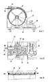
- FIG. 1 shows a schematic vertical cross section of the device in accordance with the invention,
- FIG. 2 shows a schematic horizontal cross section of said device, and
- FIG. 3 shows a vertical cross section of a detail of the device rotated 90° from the one shown in FIG. 1.
- With particular reference to the annexed drawings there is described below a preferred form of embodiment of the device in accordance with the invention adapted for cleaning the inside of the tubes of a heat exchanger with a tube nest.
- On a wheeled cart 1 there is mounted a
container 2 which encloses adrum 3 whoseexternal surface 4 is appropriately shaped with adouble groove 5 which allows simultaneous winding or unwinding of twohoses drum 3 by a series ofrollers 6 arranged around thedrum 3. - A
ratiomotor 8 mounted on the cart 1 moves thedrum 3 through aroller chain 9. Asecond roller chain 10 unites theshaft 11 of thedrum 3 to aworm screw 12 which moves with reciprocating motion asaddle 14 over which pass the twohoses shaft 11 of the drum is hollow and communicates with the end of thehoses hollow shaft 11 has a pressurizedseal 17 which permits connection thereof to the feed piping for pressurized cleaning. Therollers 6 have a rubberized surface and are rotated by friction with the tworubber belts 18 inserted on the side edges of thedrum 3. - The device illustrated is also equipped with a control panel which permits regulation of the feed speed of the hoses and reversal of movement on the basis of the programme set on the control panel for the length of the tube to be cleaned.
- The above device has been used on exchangers with tubes as long as 24 metres by a single operator who could operate the two cleaning hoses simultaneously with much less fatigue than when using a single hose without the device of the invention.
- Among the other advantages found in the use of the above device particularly interesting is substitution of the outlet nozzles of the pressurized water placed at the ends of the tubes with other types much more effective for cleaning but which it is not possible to use with only manual operations due to the excessive effort required of the operator for operation.
Claims (11)
- Device for the operation of flexible elements comprising the following basic parts:a) a rotating drum (3) around which are wound the flexible elements (15, 16) to be handled,b) a container (2) of said drum (3) equipped with a series of rollers (6) wich hold said flexible elements (15, 16) in adherence with the outer surface of the drum (3) and said container (2) having a transverse aperture which permits passage of the flexible elements (15, 16) from the inside of the container (2) to the outside thereof,c) a moving guide (14) for said flexible elements (15, 16) positioned transversely to the drum (3) and which moves with reciprocating motion and aids winding or unwinding of the flexible element (15, 16), onto or from the drum (3),d) one or more flexible elements (15, 16) of a length such as to meet the necessity for which the device is designed to be employed, ande) a ratiomotor (8) which drives through appropriate motion reducers and transmitters rotation of the drum (3) and movement of the moving guide (14) in a mutually coordinated manner.
- Device in accordance with claim 1, characterized in that motion is transmitted from the ratiomotor (8) to the drum (3) through a roller chain (9).
- Device in accordance with claim 1, characterized in that the moving guide (14) is moved by a worm screw (12) connected through a roller chain (10) to the drum shaft (11).
- Device in accordance with claim 1, characterized in that the ratio of the drum (3) diameter to that of the flexible element (15, 16) is such as to permit winding and unwinding of the flexible element (15, 16) within the allowed distortion limits of the hose.
- Device in accordance with claim 1, characterized in that the width of the drum (3) is such as to permit winding of the flexible elements (15, 16) in such a manner that the coils of the flexible elements (15, 16) wound do not overlap.
- Device in accordance with claim 1, characterized in that the ratio of the diameter of the rollers (6) to that of the drum (3) is typically between 1:30 and 1:10.
- Device in accordance with claim 1, characterized in that the rollers (6) have two central axial pivots which allow them free rotation while holding them at the same time in position around the drum (3) and interacting with two circular guides made in the side walls of the container.
- Device in accordance with claim 1, characterized in that said rollers (6) rotate by friction with the outer edges of said drum (3) both the outer edges of the drum (3) and the rollers (6) being covered with rubber or other elastomeric substance.
- Device in accordance with claim 1, characterized in that said rollers (6) rotate by friction with the outer edges of said drum on which are inserted two belts (18), one on each side, of rubber or other elastomeric substance of a thickness such as to assure contact with said rollers (6).
- Device in accordance with claim 1, characterized in that the flexible elements (15, 16) consist of hoses which carry water under pressure and are used for cleaning tube nests.
- Device in accordance with claim 1, characterized in that said drum (3) has a diameter of 80cm and a width of 45cm and permits winding of 50m of hose having a diameter between 1.4cm and 1.6cm.
Applications Claiming Priority (2)
| Application Number | Priority Date | Filing Date | Title |
|---|---|---|---|
| IT1960890 | 1990-03-08 | ||
| IT1960890A IT1239357B (en) | 1990-03-08 | 1990-03-08 | DEVICE FOR THE OPERATION OF FLEXIBLE ELEMENTS |
Publications (2)
| Publication Number | Publication Date |
|---|---|
| EP0446653A1 true EP0446653A1 (en) | 1991-09-18 |
| EP0446653B1 EP0446653B1 (en) | 1995-10-25 |
Family
ID=11159507
Family Applications (1)
| Application Number | Title | Priority Date | Filing Date |
|---|---|---|---|
| EP19910102239 Expired - Lifetime EP0446653B1 (en) | 1990-03-08 | 1991-02-18 | Device for operating flexible elements |
Country Status (6)
| Country | Link |
|---|---|
| US (1) | US5183218A (en) |
| EP (1) | EP0446653B1 (en) |
| AT (1) | ATE129483T1 (en) |
| DE (1) | DE69114032T2 (en) |
| ES (1) | ES2081378T3 (en) |
| IT (1) | IT1239357B (en) |
Cited By (9)
| Publication number | Priority date | Publication date | Assignee | Title |
|---|---|---|---|---|
| EP0555277A1 (en) * | 1990-10-31 | 1993-08-18 | Barry Bros. Specialised Services Pty Ltd | Apparatus for projecting devices through tubes and conduits |
| FR2698622A1 (en) * | 1992-12-02 | 1994-06-03 | Poujoulat Sa | Flexible hose reel. |
| EP0607629A1 (en) * | 1992-12-16 | 1994-07-27 | Peinemann Equipment B.V. | Lance machine with flexible lance |
| WO2000017595A1 (en) * | 1998-09-23 | 2000-03-30 | Idrojet S.A.S. | Cleaning device |
| EP1077094A1 (en) * | 1999-08-14 | 2001-02-21 | Alfred Kärcher GmbH & Co. | High pressure cleaning device |
| KR20030034778A (en) * | 2001-10-26 | 2003-05-09 | 조시대 | Hose automatic collection bobin apparatus |
| GB2382564A (en) * | 2001-03-05 | 2003-06-04 | Harry Gerard Bombardi | An apparatus for retracting a hose |
| US6776705B2 (en) | 2001-03-05 | 2004-08-17 | Boom Air, L.L.C. | Apparatus and a method for supplying conditioned air to an aircraft |
| CN104097993A (en) * | 2014-07-03 | 2014-10-15 | 国家电网公司 | Electric cable reel installation |
Families Citing this family (10)
| Publication number | Priority date | Publication date | Assignee | Title |
|---|---|---|---|---|
| US5865392A (en) * | 1998-04-20 | 1999-02-02 | Atlantic Richfield Company | Coiled-tubing reel having a mechanical restraint |
| BE1011896A3 (en) * | 1998-04-29 | 2000-02-01 | Reels Besloten Vennootschap Me | Improved hose reel. |
| US6264128B1 (en) | 1998-12-14 | 2001-07-24 | Schlumberger Technology Corporation | Levelwind system for coiled tubing reel |
| USD419961S (en) * | 1999-01-27 | 2000-02-01 | Great Stuff, Inc. | Housing for a hose/electrical cable reel |
| US6279848B1 (en) | 2000-04-14 | 2001-08-28 | Great Stuff, Inc. | Reel having an improved reciprocating mechanism |
| US20060273213A1 (en) * | 2005-06-06 | 2006-12-07 | Jason Turk | Level-wind system for coiled tubing |
| US8500055B2 (en) * | 2006-02-23 | 2013-08-06 | Schlumberger Technology Corporation | Coil tubing system |
| WO2009065108A1 (en) * | 2007-11-16 | 2009-05-22 | Kristen Omli | Pool lane line reel apparatuses, systems, and methods |
| US8794563B2 (en) * | 2010-05-17 | 2014-08-05 | Asm Assembly Automation Ltd | Integrated connector assembly for a rotary apparatus |
| US8720811B2 (en) | 2011-03-07 | 2014-05-13 | Stoneage, Inc. | Apparatus and method for storing and dispensing a pressure hose |
Citations (2)
| Publication number | Priority date | Publication date | Assignee | Title |
|---|---|---|---|---|
| FR2195229A5 (en) * | 1972-07-28 | 1974-03-01 | Caterpillar Mitsubishi Ltd | |
| DE2642462A1 (en) * | 1975-10-01 | 1977-04-14 | Nitro Nobel Ab | HOSE CONVEYOR WINCH |
Family Cites Families (11)
| Publication number | Priority date | Publication date | Assignee | Title |
|---|---|---|---|---|
| US2533592A (en) * | 1946-09-04 | 1950-12-12 | Landon Equipment Company | Vault lowering device |
| US2625373A (en) * | 1948-10-25 | 1953-01-13 | Gerald R Hunt | Line holder for winches |
| US2599423A (en) * | 1950-06-02 | 1952-06-03 | Philadelphia Valve Company | Hose reeling mechanism |
| US2976017A (en) * | 1958-07-07 | 1961-03-21 | Le Bus Royalty Company | Pressure bar for cable spooling drums |
| US3309066A (en) * | 1965-05-06 | 1967-03-14 | United Shoe Machinery Corp | Winches having overload control means |
| SU452996A1 (en) * | 1972-04-28 | 1986-08-30 | Старо-Краматорский Машиностроительный Завод Им.Серго Орджоникидзе | Apparatus for accumulating strip |
| US3843094A (en) * | 1973-01-05 | 1974-10-22 | R Watts | Traction device |
| US4026525A (en) * | 1975-04-24 | 1977-05-31 | Declercq Maurice G | Self-tailing winch |
| US4103841A (en) * | 1977-08-26 | 1978-08-01 | Super Products Corporation | Hose reel apparatus |
| US4655399A (en) * | 1984-03-31 | 1987-04-07 | Vernon Harvey B W | Irrigation or other machine having a rotatable drum carrying a hose or other flexible element wound thereon |
| US5050813A (en) * | 1989-12-26 | 1991-09-24 | Takeshi Ishikawa | Cord retaining and winding device |
-
1990
- 1990-03-08 IT IT1960890A patent/IT1239357B/en active IP Right Grant
-
1991
- 1991-02-13 US US07/654,543 patent/US5183218A/en not_active Expired - Fee Related
- 1991-02-18 ES ES91102239T patent/ES2081378T3/en not_active Expired - Lifetime
- 1991-02-18 EP EP19910102239 patent/EP0446653B1/en not_active Expired - Lifetime
- 1991-02-18 DE DE1991614032 patent/DE69114032T2/en not_active Expired - Fee Related
- 1991-02-18 AT AT91102239T patent/ATE129483T1/en not_active IP Right Cessation
Patent Citations (2)
| Publication number | Priority date | Publication date | Assignee | Title |
|---|---|---|---|---|
| FR2195229A5 (en) * | 1972-07-28 | 1974-03-01 | Caterpillar Mitsubishi Ltd | |
| DE2642462A1 (en) * | 1975-10-01 | 1977-04-14 | Nitro Nobel Ab | HOSE CONVEYOR WINCH |
Cited By (15)
| Publication number | Priority date | Publication date | Assignee | Title |
|---|---|---|---|---|
| EP0555277A1 (en) * | 1990-10-31 | 1993-08-18 | Barry Bros. Specialised Services Pty Ltd | Apparatus for projecting devices through tubes and conduits |
| EP0555277A4 (en) * | 1990-10-31 | 1994-01-12 | Barry Bros. Specialised Services Pty Ltd | |
| FR2698622A1 (en) * | 1992-12-02 | 1994-06-03 | Poujoulat Sa | Flexible hose reel. |
| EP0600770A1 (en) * | 1992-12-02 | 1994-06-08 | Etablissements Poujoulat | Unwinding device for flexible tube |
| EP0607629A1 (en) * | 1992-12-16 | 1994-07-27 | Peinemann Equipment B.V. | Lance machine with flexible lance |
| US5397057A (en) * | 1992-12-16 | 1995-03-14 | Peinemann Equipment B.V. | Lance machine with flexible lance |
| WO2000017595A1 (en) * | 1998-09-23 | 2000-03-30 | Idrojet S.A.S. | Cleaning device |
| EP1077094A1 (en) * | 1999-08-14 | 2001-02-21 | Alfred Kärcher GmbH & Co. | High pressure cleaning device |
| GB2382564A (en) * | 2001-03-05 | 2003-06-04 | Harry Gerard Bombardi | An apparatus for retracting a hose |
| GB2382564B (en) * | 2001-03-05 | 2004-02-18 | Harry Gerard Bombardi | A device and a method for supplying conditioned air to an aircraft |
| US6776705B2 (en) | 2001-03-05 | 2004-08-17 | Boom Air, L.L.C. | Apparatus and a method for supplying conditioned air to an aircraft |
| US6821201B2 (en) | 2001-03-05 | 2004-11-23 | Boomair, L.L.C. | Device and a method for supplying conditioned air to an aircraft |
| US6834668B2 (en) | 2001-03-05 | 2004-12-28 | Boom Air, Llc | Device and a method for supplying conditioned air to an aircraft |
| KR20030034778A (en) * | 2001-10-26 | 2003-05-09 | 조시대 | Hose automatic collection bobin apparatus |
| CN104097993A (en) * | 2014-07-03 | 2014-10-15 | 国家电网公司 | Electric cable reel installation |
Also Published As
| Publication number | Publication date |
|---|---|
| DE69114032D1 (en) | 1995-11-30 |
| US5183218A (en) | 1993-02-02 |
| EP0446653B1 (en) | 1995-10-25 |
| DE69114032T2 (en) | 1996-04-11 |
| ES2081378T3 (en) | 1996-03-01 |
| ATE129483T1 (en) | 1995-11-15 |
| IT1239357B (en) | 1993-10-20 |
| IT9019608A1 (en) | 1991-09-08 |
| IT9019608A0 (en) | 1990-03-08 |
Similar Documents
| Publication | Publication Date | Title |
|---|---|---|
| US5183218A (en) | Device for the operation of hoses containing a liquid under very high pressure | |
| CA2786160C (en) | Apparatus, system and method for cleaning heat exchanger tubes | |
| CN103282128B (en) | Apparatus for internally treating pipes | |
| CA2540067A1 (en) | High pressure tube cleaning apparatus | |
| DE3148225C2 (en) | ||
| EP0027388B1 (en) | Decontamination method and apparatus | |
| US5078162A (en) | Cleaning apparatus for tubes | |
| JP3227514B2 (en) | Pipe feeding and winding device | |
| DE102010051657B4 (en) | Cleaning device for a combustion boiler | |
| EP3173727A2 (en) | Device for cleaning flue pipes of a boiler plant with a cleaning hose | |
| US4656685A (en) | Duct cleaner | |
| DE19643958A1 (en) | Transportation helix for spraying of cleaning agent | |
| WO1995019853A1 (en) | Applying coatings to tubing interiors | |
| WO1994029632A1 (en) | Process and device for lining pipes, in particular for sanitary purposes | |
| US20150246789A1 (en) | Hose reel assembly | |
| DE3590518C2 (en) | ||
| DE2448932A1 (en) | Device for internally coating tubes - having double collars with polymer between and drawn through tube | |
| WO2000017595A1 (en) | Cleaning device | |
| WO1995033174A1 (en) | A method and an apparatus for cleaning a gun barrel | |
| EP0493402B1 (en) | Device for cleaning the insides of heat-exchanger tubes | |
| DE4102663A1 (en) | DEVICE FOR TREATING PIPE SURFACES | |
| SE507502C2 (en) | Cleaning device for press rolls in a pulp machine | |
| DE8512875U1 (en) | Device for cleaning especially small-caliber pipes | |
| DE102004013304A1 (en) | System for removing encrustations from underground tanks comprises vehicle which moves over encrustation and sprays treatment liquid on to it, pump at distance from vehicle recirculating liquid through heating and pH adjusting units | |
| DE102011010638A1 (en) | Method for cleaning fire-tube boiler for ship, involves pushing tube brush forward by driving vibrating device until brush emerges from opening |
Legal Events
| Date | Code | Title | Description |
|---|---|---|---|
| PUAI | Public reference made under article 153(3) epc to a published international application that has entered the european phase |
Free format text: ORIGINAL CODE: 0009012 |
|
| AK | Designated contracting states |
Kind code of ref document: A1 Designated state(s): AT BE CH DE DK ES FR GB GR IT LI LU NL SE |
|
| 17P | Request for examination filed |
Effective date: 19920309 |
|
| 17Q | First examination report despatched |
Effective date: 19930902 |
|
| GRAA | (expected) grant |
Free format text: ORIGINAL CODE: 0009210 |
|
| AK | Designated contracting states |
Kind code of ref document: B1 Designated state(s): AT BE CH DE DK ES FR GB GR IT LI LU NL SE |
|
| PG25 | Lapsed in a contracting state [announced via postgrant information from national office to epo] |
Ref country code: GR Free format text: LAPSE BECAUSE OF FAILURE TO SUBMIT A TRANSLATION OF THE DESCRIPTION OR TO PAY THE FEE WITHIN THE PRESCRIBED TIME-LIMIT Effective date: 19951025 Ref country code: DK Effective date: 19951025 Ref country code: BE Effective date: 19951025 |
|
| REF | Corresponds to: |
Ref document number: 129483 Country of ref document: AT Date of ref document: 19951115 Kind code of ref document: T |
|
| REF | Corresponds to: |
Ref document number: 69114032 Country of ref document: DE Date of ref document: 19951130 |
|
| PGFP | Annual fee paid to national office [announced via postgrant information from national office to epo] |
Ref country code: FR Payment date: 19951229 Year of fee payment: 6 |
|
| PGFP | Annual fee paid to national office [announced via postgrant information from national office to epo] |
Ref country code: GB Payment date: 19960111 Year of fee payment: 6 |
|
| ITF | It: translation for a ep patent filed |
Owner name: NOTARBARTOLO & GERVASI S.R.L. |
|
| REG | Reference to a national code |
Ref country code: CH Ref legal event code: NV Representative=s name: R. A. EGLI & CO. PATENTANWAELTE |
|
| PG25 | Lapsed in a contracting state [announced via postgrant information from national office to epo] |
Ref country code: SE Effective date: 19960125 |
|
| PG25 | Lapsed in a contracting state [announced via postgrant information from national office to epo] |
Ref country code: LU Free format text: LAPSE BECAUSE OF NON-PAYMENT OF DUE FEES Effective date: 19960229 |
|
| PGFP | Annual fee paid to national office [announced via postgrant information from national office to epo] |
Ref country code: NL Payment date: 19960229 Year of fee payment: 6 Ref country code: ES Payment date: 19960229 Year of fee payment: 6 Ref country code: AT Payment date: 19960229 Year of fee payment: 6 |
|
| ET | Fr: translation filed | ||
| REG | Reference to a national code |
Ref country code: ES Ref legal event code: FG2A Ref document number: 2081378 Country of ref document: ES Kind code of ref document: T3 |
|
| PGFP | Annual fee paid to national office [announced via postgrant information from national office to epo] |
Ref country code: CH Payment date: 19960805 Year of fee payment: 6 |
|
| PLBE | No opposition filed within time limit |
Free format text: ORIGINAL CODE: 0009261 |
|
| STAA | Information on the status of an ep patent application or granted ep patent |
Free format text: STATUS: NO OPPOSITION FILED WITHIN TIME LIMIT |
|
| 26N | No opposition filed | ||
| PG25 | Lapsed in a contracting state [announced via postgrant information from national office to epo] |
Ref country code: GB Effective date: 19970218 Ref country code: AT Effective date: 19970218 |
|
| PG25 | Lapsed in a contracting state [announced via postgrant information from national office to epo] |
Ref country code: ES Free format text: LAPSE BECAUSE OF NON-PAYMENT OF DUE FEES Effective date: 19970219 |
|
| PG25 | Lapsed in a contracting state [announced via postgrant information from national office to epo] |
Ref country code: LI Effective date: 19970228 Ref country code: CH Effective date: 19970228 |
|
| PG25 | Lapsed in a contracting state [announced via postgrant information from national office to epo] |
Ref country code: NL Effective date: 19970901 |
|
| GBPC | Gb: european patent ceased through non-payment of renewal fee |
Effective date: 19970218 |
|
| REG | Reference to a national code |
Ref country code: CH Ref legal event code: PL |
|
| PG25 | Lapsed in a contracting state [announced via postgrant information from national office to epo] |
Ref country code: FR Effective date: 19971030 |
|
| NLV4 | Nl: lapsed or anulled due to non-payment of the annual fee |
Effective date: 19970901 |
|
| REG | Reference to a national code |
Ref country code: FR Ref legal event code: ST |
|
| REG | Reference to a national code |
Ref country code: ES Ref legal event code: FD2A Effective date: 19990503 |
|
| PGFP | Annual fee paid to national office [announced via postgrant information from national office to epo] |
Ref country code: DE Payment date: 20000331 Year of fee payment: 10 |
|
| PG25 | Lapsed in a contracting state [announced via postgrant information from national office to epo] |
Ref country code: DE Free format text: LAPSE BECAUSE OF NON-PAYMENT OF DUE FEES Effective date: 20011201 |
|
| PG25 | Lapsed in a contracting state [announced via postgrant information from national office to epo] |
Ref country code: IT Free format text: LAPSE BECAUSE OF NON-PAYMENT OF DUE FEES;WARNING: LAPSES OF ITALIAN PATENTS WITH EFFECTIVE DATE BEFORE 2007 MAY HAVE OCCURRED AT ANY TIME BEFORE 2007. THE CORRECT EFFECTIVE DATE MAY BE DIFFERENT FROM THE ONE RECORDED. Effective date: 20050218 |