EP0447021A2 - Composite cap including tamper indicating band - Google Patents
Composite cap including tamper indicating band Download PDFInfo
- Publication number
- EP0447021A2 EP0447021A2 EP91300443A EP91300443A EP0447021A2 EP 0447021 A2 EP0447021 A2 EP 0447021A2 EP 91300443 A EP91300443 A EP 91300443A EP 91300443 A EP91300443 A EP 91300443A EP 0447021 A2 EP0447021 A2 EP 0447021A2
- Authority
- EP
- European Patent Office
- Prior art keywords
- fingers
- band
- tamper indicating
- indicating band
- container
- Prior art date
- Legal status (The legal status is an assumption and is not a legal conclusion. Google has not performed a legal analysis and makes no representation as to the accuracy of the status listed.)
- Granted
Links
Images

Classifications
-
- B—PERFORMING OPERATIONS; TRANSPORTING
- B65—CONVEYING; PACKING; STORING; HANDLING THIN OR FILAMENTARY MATERIAL
- B65D—CONTAINERS FOR STORAGE OR TRANSPORT OF ARTICLES OR MATERIALS, e.g. BAGS, BARRELS, BOTTLES, BOXES, CANS, CARTONS, CRATES, DRUMS, JARS, TANKS, HOPPERS, FORWARDING CONTAINERS; ACCESSORIES, CLOSURES, OR FITTINGS THEREFOR; PACKAGING ELEMENTS; PACKAGES
- B65D41/00—Caps, e.g. crown caps or crown seals, i.e. members having parts arranged for engagement with the external periphery of a neck or wall defining a pouring opening or discharge aperture; Protective cap-like covers for closure members, e.g. decorative covers of metal foil or paper
- B65D41/32—Caps or cap-like covers with lines of weakness, tearing-strips, tags, or like opening or removal devices, e.g. to facilitate formation of pouring openings
- B65D41/34—Threaded or like caps or cap-like covers provided with tamper elements formed in, or attached to, the closure skirt
- B65D41/3423—Threaded or like caps or cap-like covers provided with tamper elements formed in, or attached to, the closure skirt with flexible tabs, or elements rotated from a non-engaging to an engaging position, formed on the tamper element or in the closure skirt
- B65D41/3428—Threaded or like caps or cap-like covers provided with tamper elements formed in, or attached to, the closure skirt with flexible tabs, or elements rotated from a non-engaging to an engaging position, formed on the tamper element or in the closure skirt the tamper element being integrally connected to the closure by means of bridges
Definitions
- This invention relates in general to new and useful improvements in closure caps for containers, and more particularly to closure caps having tamper indicating bands.
- this invention relates to a closure cap component which is provided with a tamper indicating band. At the lower edge of the band there is provided a plurality of fingers which lock beneath the retaining bead on a container neck finish.
- the fingers are arranged in groups with the fingers of each group being interconnected by a connecting bridge.
- the fingers When the fingers are initially molded, they extend radially inwardly and axially downwardly and prior to the tamper indicating band being applied to a container as part of a closure cap, the fingers are folded to extend radially inwardly, but axially upwardly.
- the fingers are arranged in groups with fingers of each group being permanently linked together adjacent their tips by a connecting bridge.
- the bridge performs two functions. First, the connecting bridge increases the ability of the fingers to stay folded up in their working position. Once grouped by the connecting bridge, the tendency of the fingers to stay up is greatly increased over that of a single finger. Secondly, the bridges are small enough to allow water sprays to have access to the area between the tamper indicating band and the container neck finish which permits the removal of an excess product.
- connecting bridges With respect to the connecting bridges retaining the flaps in their operative positions, it is to be understood that as the flaps are folded from their as molded position to their operative position, the connecting bridges stretch and provide for a snap action as the flaps move over center.
- tamper indicating band construction could be utilized as an integral part of a molded plastic closure cap.
- Fig. 1 is an elevational view of a closure cap as molded and shows generally the details of the connections between the fingers.
- Fig. 2 is a vertical sectional view taken through the as molded over cap and applied to a metal shell of a closure cap, the view being taken generally alone the line 2-2 of Fig. 1.
- Fig. 3 is a view similar to Fig. 2 but shows the closure cap, including the overcap, applied to a container.
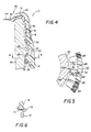
- Fig. 4 is a vertical sectional view similar to Fig. 3, but rotated circumferentially so as to illustrate the circumferential interlock of a nib on the tamper indicating band and a rib on the container neck finish.
- Fig. 5 is a fragmentary horizontal sectional view taken generally along the line 5-5 of Fig.4 and shows the specific relationship of the interlock between the nib and the rib.
- Fig. 6 is a fragmentary vertical sectional view showing a modified form of connection between the tamper indicating band and the overcap.
- FIGs. 1 and 2 there is illustrated in Figs. 1 and 2 an overcap formed in accordance with this invention and utilizing the tamper indicating band which is the subject of this invention.
- the overcap is generally identified by the numeral 10 and, as is best shown in Fig. 2, includes an upper annular flange 12 from which an integral skirt 14 depends. The upper portion of the skirt 14 is provided with knurling 16.
- the skirt 14 has integrally formed therewith a tamper indicating band 18 which is removably secured to the lower edge of the skirt 14 by a plurality of circumferentially spaced, rupturable bridges 20. It is to be understood that the tamper indicating band 18 is otherwise separate from the skirt 14 and is spaced thereform by way of a groove 22.
- Each of the rupturable bridges 20 is located within an opening 24 having a lower boundary 26.
- Each opening 24, as well as the associated rupturable bridge 20, is defined by retractable blades (not shown) forming part of the mold in which the overcap 10 is formed.
- the surfaces 26 function as push-blocks to aid in the ejection the overcap 10 from an associated mold. These push-blocks 26 also help prevent distortion and breakage of the bridge area when the associated edge of the tamper indicating band 18 is being pushed during ejection of the overcap 10 from the injection mold.
- the tamper indicating band 18 in order that the tamper indicating band 18 may be locked on a container beneath a retaining bead of a container neck finish (to be described in detail hereinafter), there is intergrally molded with the lower edge of the tamper indicating band 18 a plurality of individual flaps 28.
- Each of the flaps 28 is generally of a triangular cross section and has a narrow hinged connection 30 with the tamper indicating band while terminating in a relatively thick tip 32.
- the flaps 28 are distinguished in that they are arranged in groups with the flaps 28 of each group being joined together by connecting bridges 34. It is preferred that the flaps 34 in each group be at least three in number.
- each flap 28 has its hinged connection 30 with the tamper indicating band at the lower inside of the tamper indicating band 18.
- the closure cap 40 is of a conventional type and includes a metal shell 42.
- the metal shell 42 includes an end panel 44 of which a radially outer portion is in the form of a downwardly opening channel 46.
- the shell 42 also includes a depending skirt 48 which is of a generally stepped configuration so that the lower portion thereof is of a greater diameter than the upper portion.
- the skirt 48 terminates in an outwardly and upwardly configurated curl 50.
- the end panel 44 is provided with a central vacuum loss indicating button 52.
- the shell 42 is provided with a suitable sealing compound 54, such as plastisol, which fills the channel 46 and also lines the skirt 48.
- the sealing compound 54 which lines the skirt 48 serves to form threads to facilitate the removal of the closure cap 40 in a manner to be described hereinafter.
- the lower portion of the skirt 14 is provided on the radially inner surface thereof with an annular groove 56. While it is preferred that there be an interference fit between the overcap 10 and the shell 42, and the stepped configuration of the skirt 48 as well as the connection of the curl 50 with the skirt 14 facilitating this, in certain instances it may be necessary to bond the overcap 10 to the shell 42 by way of an adhesive. It will be readily apparent that when the overcap 10 is forced down over the shell 42, any excess adhesive will be extruded towards the curl 50. By making the groove 56 of a greater height than the curl 50, there is provided a well 58 for the excess adhesive.
- the closure cap 40 has been applied to a container 60 which includes an end sealing surface 62 and has external upper threads 64. Spaced below the threads 64, the neck finish of the container 60 includes a retaining bead 66.
- the closure cap 40 With the flaps 28 in their upwardly folded positions, the closure cap 40 is pressed down onto to the neck finish of the container 60. As a result, the sealing surface 62 will become embedded within the sealing compound 54 generally within the channel 46. Further, the sealing compound which lines the skirt 48 flows around the threads 64 and forms in that sealing compound matching threads.
- the flaps 28 will engage and ride over the retaining bead 66.
- the flaps 28 serve to lock the tamper indicating band 18 onto the container neck finish against removal.
- the tamper indicating band 18 is provided with circumferentially spaced, radially inwardly directed nibs 68.
- the nibs 68 are disposed below the retaining bead 66 and are positioned to engage circumferentially behind radially outwardly projecting ribs 70 formed on the neck finish of the container 60 below the retaining bead 66. This is best shown in Fig. 5.
- tamper indicating band 18 when the closure cap 40 and the overcap 10 are twisted or rotated to effect removal of the closure cap 40 from the container 60, the tamper indicating band 18 will be prevented from rotating with the thought that the rupturable bridges 20 will rupture to indicate cap rotation before the seal between the end finish 62 and the sealing compound 54 is broken. In any event, the tamper indicating band 18 may be released no later than the time at which the vacuum within the container 60 is released so as to permit the eversion of the bubble 52 to indicate loss of vacuum.
- each nib 68 is aligned with a space 72. It is further to be understood that the space 72 is exaggerated in Fig. 5 and that the space 72 need not provide clearance for the ribs 70 although this has been so illustrated.
- the linked group of flaps provides a definite advantage.
- the connecting bridges 34 perform two functions. The first is increased ability of the flaps 28 to stay folded up in their working position. Once grouped by the connecting bridges 34, the tendency of the flaps 28 to stay up is greatly increased over that of individual flaps. Further, as the flaps 28 are folded from the their as molded position to their operative positions, the connecting bridges 34 can stretch and as the flaps 28 of each group reaches an over center position, a snap action is provided by the connecting bridges 34 to urge the flaps of the group to their upstanding positions.
- a second advantage of the flaps 28 being joined in groups by the connecting bridges 34 is that the connecting bridges 34 are small enough to allow water sprays to still have access to the area between the tamper indicating band and the neck finish of the container 60. In many applications, this area can collect food products or like products squeezed down as excess from the upper finish area of the container. The lack of water access to a drainage from this area, as is in the case of a continuous flap, could result in mold growth and undesirable conditions. Cleansing water is free to enter and drain from between the overcap 10 and the tamper indicating band 18 between the fracturable bridges 20 and also between the remaining gaps between individual flap segments. Drying air flow is also enhanced. Finally, the open construction resulting from lightly bridging the flaps 28 into groups allows much less opportunity for entrapment of a product or water.
- flaps 28 being connected into groups by the connecting bridges 34 is that the easy pivotal action of the flap groups allows for lighter capping pressures since dimensional fits between the tamper band and the container need not be as tight as they would be if a solid or continuous flap replaced the individual flaps. It will be readily apparent that the tamper band 18 need not expand during application of the closure cap.
- the flaps 28 flex out of the way and then lock under the corresponding retaining bead 66.
- the connecting bridges 34 linking the flaps 28 are sufficiently thin and the connecting bridges 34 can stretch while the flaps 28 are flexed radially outwardly during capping since at this time the flap tips are moving slightly further apart. This freedom of movement allowed by the stretching, or even breaking, of the connecting bridges 38 decreases the structural rigidity of the flap groups, especially in longer lengths.
- the decreased rigidity of the flap groups during application of the closure cap further lowers required application pressures and distortion of the tamper indicating band 18 and the rupturable bridges 20.
- This is beneficial in sensitive applications such as when the overcap is applied as an after step following the closing of the container utilizing the closure cap 40 per se or when the tamper indicating band 18 is utilized as an integral part of a one-piece plastic continuous thread closure (not shown) where capping becomes more difficult when the tamper indicating band resists the easy thread-on motion needed by many cappers. Extra resistance here can cause the closure cap to misalign and cross thread or cause the tamper indicating band to collapse and fold under the overcap skirt.
- the connecting bridges 34 are sturdy enough to withstand demolding and folding upward to hold the groups in position during capping. Stretching or breaking during capping under these conditions is not only harmless, but can even be beneficial.
- Fig. 6 wherein the manner of integrally attaching the tamper indicating band 18 to the overcap skirt 16 is illustrated.
- the tamper indicating band 18 can initially be directly integral with the skirt 16 of the overcap 10 and there can be provided at circumferentially spaced integrals projections 72 which overlap the line of connection between the tamper indicating band 18 and the skirt 16. Then, a slot 74 may be sawed or otherwise formed separating the tamper indicating band 18 from the skirt 16 except for the projections 72 which now function as rupturable bridges.
- closure cap and most particularly the tamper indicating band thereof have been specifically illustrated and described herein, it is to be understood that minor variations may be made in the tamper band construction and the associated overcap without departing from the spirit and scope of the invention as defined by the appended claims.
Abstract
Description
- This invention relates in general to new and useful improvements in closure caps for containers, and more particularly to closure caps having tamper indicating bands.
- Most specifically, this invention relates to a closure cap component which is provided with a tamper indicating band. At the lower edge of the band there is provided a plurality of fingers which lock beneath the retaining bead on a container neck finish. The fingers are arranged in groups with the fingers of each group being interconnected by a connecting bridge.
- When the fingers are initially molded, they extend radially inwardly and axially downwardly and prior to the tamper indicating band being applied to a container as part of a closure cap, the fingers are folded to extend radially inwardly, but axially upwardly. The fingers are arranged in groups with fingers of each group being permanently linked together adjacent their tips by a connecting bridge. The bridge performs two functions. First, the connecting bridge increases the ability of the fingers to stay folded up in their working position. Once grouped by the connecting bridge, the tendency of the fingers to stay up is greatly increased over that of a single finger. Secondly, the bridges are small enough to allow water sprays to have access to the area between the tamper indicating band and the container neck finish which permits the removal of an excess product.
- With respect to the connecting bridges retaining the flaps in their operative positions, it is to be understood that as the flaps are folded from their as molded position to their operative position, the connecting bridges stretch and provide for a snap action as the flaps move over center.
- Although a preferred utilization of the tamper indicating band is in connection with an overcap, it is to be understood that the tamper indicating band construction could be utilized as an integral part of a molded plastic closure cap.
- With the above and other objects in view that will hereinafter appear, the nature of the invention will be more clearly understood by reference to the following detailed description, the appended claims, and the several views illustrated in the accompanying drawings.
- Fig. 1 is an elevational view of a closure cap as molded and shows generally the details of the connections between the fingers.
- Fig. 2 is a vertical sectional view taken through the as molded over cap and applied to a metal shell of a closure cap, the view being taken generally alone the line 2-2 of Fig. 1.
- Fig. 3 is a view similar to Fig. 2 but shows the closure cap, including the overcap, applied to a container.
- Fig. 4 is a vertical sectional view similar to Fig. 3, but rotated circumferentially so as to illustrate the circumferential interlock of a nib on the tamper indicating band and a rib on the container neck finish.
- Fig. 5 is a fragmentary horizontal sectional view taken generally along the line 5-5 of Fig.4 and shows the specific relationship of the interlock between the nib and the rib.
- Fig. 6 is a fragmentary vertical sectional view showing a modified form of connection between the tamper indicating band and the overcap.
- Referring now to the drawings in detail, it will be seen that there is illustrated in Figs. 1 and 2 an overcap formed in accordance with this invention and utilizing the tamper indicating band which is the subject of this invention. The overcap is generally identified by the
numeral 10 and, as is best shown in Fig. 2, includes an upperannular flange 12 from which anintegral skirt 14 depends. The upper portion of theskirt 14 is provided with knurling 16. - The
skirt 14 has integrally formed therewith atamper indicating band 18 which is removably secured to the lower edge of theskirt 14 by a plurality of circumferentially spaced,rupturable bridges 20. It is to be understood that thetamper indicating band 18 is otherwise separate from theskirt 14 and is spaced thereform by way of agroove 22. Each of therupturable bridges 20 is located within an opening 24 having alower boundary 26. Each opening 24, as well as the associatedrupturable bridge 20, is defined by retractable blades (not shown) forming part of the mold in which theovercap 10 is formed. Thesurfaces 26 function as push-blocks to aid in the ejection theovercap 10 from an associated mold. These push-blocks 26 also help prevent distortion and breakage of the bridge area when the associated edge of thetamper indicating band 18 is being pushed during ejection of theovercap 10 from the injection mold. - At this time it is pointed out that it is known to provide a tamper indicating band with a depending flange which is continuous and which is folded up for engagement beneath a retaining bead of an associated container neck finish. It is also known to form the band in the form of individual flaps.
- In accordance with, this invention, in order that the
tamper indicating band 18 may be locked on a container beneath a retaining bead of a container neck finish (to be described in detail hereinafter), there is intergrally molded with the lower edge of the tamper indicating band 18 a plurality ofindividual flaps 28. Each of theflaps 28 is generally of a triangular cross section and has a narrow hingedconnection 30 with the tamper indicating band while terminating in a relativelythick tip 32. Theflaps 28 are distinguished in that they are arranged in groups with theflaps 28 of each group being joined together by connectingbridges 34. It is preferred that theflaps 34 in each group be at least three in number. - As is best shown in Fig. 2, each
flap 28 has its hingedconnection 30 with the tamper indicating band at the lower inside of thetamper indicating band 18. - Referring now most specifically to Fig. 2, it will be seen that the
overcap 10 is applied to a closure cap generally identified by thenumeral 40. Theclosure cap 40 is of a conventional type and includes ametal shell 42. Themetal shell 42 includes anend panel 44 of which a radially outer portion is in the form of a downwardly openingchannel 46. Theshell 42 also includes a dependingskirt 48 which is of a generally stepped configuration so that the lower portion thereof is of a greater diameter than the upper portion. Theskirt 48 terminates in an outwardly and upwardly configuratedcurl 50. - As best shown in Fig. 3, the
end panel 44 is provided with a central vacuumloss indicating button 52. - Referring once again to Fig. 2, it will be seen that the
shell 42 is provided with asuitable sealing compound 54, such as plastisol, which fills thechannel 46 and also lines theskirt 48. The sealingcompound 54 which lines theskirt 48 serves to form threads to facilitate the removal of theclosure cap 40 in a manner to be described hereinafter. - In order to provide clearance for the
curl 50, the lower portion of theskirt 14 is provided on the radially inner surface thereof with anannular groove 56. While it is preferred that there be an interference fit between theovercap 10 and theshell 42, and the stepped configuration of theskirt 48 as well as the connection of thecurl 50 with theskirt 14 facilitating this, in certain instances it may be necessary to bond theovercap 10 to theshell 42 by way of an adhesive. It will be readily apparent that when theovercap 10 is forced down over theshell 42, any excess adhesive will be extruded towards thecurl 50. By making thegroove 56 of a greater height than thecurl 50, there is provided awell 58 for the excess adhesive. - Referring now to Fig. 3, it will be seen that the
closure cap 40 has been applied to acontainer 60 which includes anend sealing surface 62 and has externalupper threads 64. Spaced below thethreads 64, the neck finish of thecontainer 60 includes a retaining bead 66. - With the
flaps 28 in their upwardly folded positions, theclosure cap 40 is pressed down onto to the neck finish of thecontainer 60. As a result, the sealingsurface 62 will become embedded within the sealingcompound 54 generally within thechannel 46. Further, the sealing compound which lines theskirt 48 flows around thethreads 64 and forms in that sealing compound matching threads. - As the
closure cap 40, together with theovercap 10, is pressed down onto thecontainer 60, theflaps 28 will engage and ride over the retaining bead 66. Thus theflaps 28 serve to lock thetamper indicating band 18 onto the container neck finish against removal. - Referring now to Figs. 4 and 5, it will be seen that the
tamper indicating band 18 is provided with circumferentially spaced, radially inwardly directednibs 68. Thenibs 68 are disposed below the retaining bead 66 and are positioned to engage circumferentially behind radially outwardly projectingribs 70 formed on the neck finish of thecontainer 60 below the retaining bead 66. This is best shown in Fig. 5. - It will be readily apparent from Fig. 5 that when the
closure cap 40 and theovercap 10 are twisted or rotated to effect removal of theclosure cap 40 from thecontainer 60, thetamper indicating band 18 will be prevented from rotating with the thought that therupturable bridges 20 will rupture to indicate cap rotation before the seal between theend finish 62 and the sealingcompound 54 is broken. In any event, thetamper indicating band 18 may be released no later than the time at which the vacuum within thecontainer 60 is released so as to permit the eversion of thebubble 52 to indicate loss of vacuum. - It is to be understood that the groups of
flaps 28 joined together by thebridges 34 are spaced apart as at 72. Further, it is to be understood that eachnib 68 is aligned with aspace 72. It is further to be understood that thespace 72 is exaggerated in Fig. 5 and that thespace 72 need not provide clearance for theribs 70 although this has been so illustrated. - In any event, the engagement of the
flaps 28 under the retaining bead 66 prevents removal of thetamper indicating band 18 with the closure cap. - The linked group of flaps provides a definite advantage. The connecting
bridges 34 perform two functions. The first is increased ability of theflaps 28 to stay folded up in their working position. Once grouped by the connectingbridges 34, the tendency of theflaps 28 to stay up is greatly increased over that of individual flaps. Further, as theflaps 28 are folded from the their as molded position to their operative positions, the connectingbridges 34 can stretch and as theflaps 28 of each group reaches an over center position, a snap action is provided by the connectingbridges 34 to urge the flaps of the group to their upstanding positions. - A second advantage of the
flaps 28 being joined in groups by the connectingbridges 34 is that the connectingbridges 34 are small enough to allow water sprays to still have access to the area between the tamper indicating band and the neck finish of thecontainer 60. In many applications, this area can collect food products or like products squeezed down as excess from the upper finish area of the container. The lack of water access to a drainage from this area, as is in the case of a continuous flap, could result in mold growth and undesirable conditions. Cleansing water is free to enter and drain from between theovercap 10 and thetamper indicating band 18 between thefracturable bridges 20 and also between the remaining gaps between individual flap segments. Drying air flow is also enhanced. Finally, the open construction resulting from lightly bridging theflaps 28 into groups allows much less opportunity for entrapment of a product or water. - Another advantage of the
flaps 28 being connected into groups by the connectingbridges 34 is that the easy pivotal action of the flap groups allows for lighter capping pressures since dimensional fits between the tamper band and the container need not be as tight as they would be if a solid or continuous flap replaced the individual flaps. It will be readily apparent that thetamper band 18 need not expand during application of the closure cap. Theflaps 28 flex out of the way and then lock under the corresponding retaining bead 66. The connecting bridges 34 linking theflaps 28 are sufficiently thin and the connectingbridges 34 can stretch while theflaps 28 are flexed radially outwardly during capping since at this time the flap tips are moving slightly further apart. This freedom of movement allowed by the stretching, or even breaking, of the connecting bridges 38 decreases the structural rigidity of the flap groups, especially in longer lengths. - The decreased rigidity of the flap groups during application of the closure cap further lowers required application pressures and distortion of the
tamper indicating band 18 and the rupturable bridges 20. This is beneficial in sensitive applications such as when the overcap is applied as an after step following the closing of the container utilizing theclosure cap 40 per se or when thetamper indicating band 18 is utilized as an integral part of a one-piece plastic continuous thread closure (not shown) where capping becomes more difficult when the tamper indicating band resists the easy thread-on motion needed by many cappers. Extra resistance here can cause the closure cap to misalign and cross thread or cause the tamper indicating band to collapse and fold under the overcap skirt. By forming the connectingbridges 34 with a thickness of .005-.012 inch, the connectingbridges 34 are sturdy enough to withstand demolding and folding upward to hold the groups in position during capping. Stretching or breaking during capping under these conditions is not only harmless, but can even be beneficial. - Reference is now made to Fig. 6 wherein the manner of integrally attaching the
tamper indicating band 18 to theovercap skirt 16 is illustrated. In lieu of the necessity of providing the mold with blades for forming the openings adjacent thebridges 20, thetamper indicating band 18 can initially be directly integral with theskirt 16 of theovercap 10 and there can be provided at circumferentially spacedintegrals projections 72 which overlap the line of connection between thetamper indicating band 18 and theskirt 16. Then, aslot 74 may be sawed or otherwise formed separating thetamper indicating band 18 from theskirt 16 except for theprojections 72 which now function as rupturable bridges. - Although only a preferred embodiment of the closure cap, and most particularly the tamper indicating band thereof have been specifically illustrated and described herein, it is to be understood that minor variations may be made in the tamper band construction and the associated overcap without departing from the spirit and scope of the invention as defined by the appended claims.
Claims (17)
- A tamper indicating band for a closure, said band being provided with a plurality of circumferentially spaced adjacent fingers extending radially inwardly and axially upwardly for engagement below a retaining bead of a container, said band being improved by said fingers being joined in groups by connecting bridges.
- A tamper indicating band according to claim 1 wherein there are at least three of said fingers in each of said groups.
- A tamper indicating band according to claim 1 wherein said connecting bridges are stretchable to permit individual flexing of fingers in each group.
- A tamper indicating band according to claim 1 wherein said fingers have free tips for engaging a retaining bead, and said connecting bridges are located adjacent said tips.
- A tamper indicating band according to claim 1 wherein said groups of fingers have spaces therebetween, and said tamper indicating band has radially inwardly directed nibs radially aligned with said spaces for engaging radially directed ribs on a container to restrict rotation of said tamper indicating band relative to a container.
- A tamper indicating band according to claim 1 wherein said band is of a molded construction and as molded said fingers extend radially inwardly and axially downwardly, and said connecting bridges form over center resilient snapping means for retaining said fingers in said radially inwardly and axially upwardly directed position once said fingers are moved to said radially inwardly and axially upwardly directed position.
- A tamper indicating band according to claim 1 wherein said fingers have hinged connections with said band, and said fingers are spaced apart adjacent said hinged connections for facilitating washing of a filled container to remove excess product.
- A tamper indicating band according to claim 1, wherein an upper edge of said band has rupturable bridges for connection to a closure cap member.
- A tamper indicating band according to claim 1, wherein an upper edge of said band has rupturable bridges for connection to an overcap.
- A closure for a container, said closure including a cap of the push-on twist-off type including a metal shell including an end panel and a depending skirt terminating in a curl, a sealing compound lining a radially outer part of said end panel to form a seal and said skirt to form thread means, a molded plastic overcap telescoped over said shell and having radially inwardly opening groove receiving said curl, said groove extending above said curl and forming a well for receiving excess of adhesive bonding said overcap to said skirt, and a tamper indicating band depending from said overcap and releasably connected to said overcap by rupturable bridges.
- A closure according to claim 10 with said band being provided with a plurality of circumferentially spaced adjacent fingers extending radially inwardly and axially upwardly for engagement below a retaining bead of a container, said band being improved by said fingers being joined in groups by connecting bridges.
- A closure according to claim 11 wherein there at least three of said fingers in each of said groups.
- A closure according to claim 11 wherein said connecting bridges are stretchable to permit individual flexing of fingers in each group.
- A closure according to claim 11 wherein said fingers have free tips for engaging a retaining bead, and said connecting bridges are located adjacent said tips.
- A closure according to claim 11 wherein said groups of fingers have spaces therebetween, and said tamper indicating band has radially inwardly directed nibs radially aligned with said spaces for engaging radially directed ribs on a container to restrict rotation of said tamper indicating band relative to a container.
- A closure according to claim 11 wherein said band is of a molded construction and as molded said fingers extend radially inwardly and axially downwardly, and said connecting bridges form over center resilient snapping means for retaining said fingers in said radially inwardly and axially upwardly directed position once said fingers are moved to said radially inwardly and axially upwardly directed position.
- A closure according to claim 11 wherein said fingers have hinged connections with said band, and said fingers are spaced apart adjacent said hinged connections for facilitating washing of a filled container to remove excess product.
Applications Claiming Priority (2)
| Application Number | Priority Date | Filing Date | Title |
|---|---|---|---|
| US493745 | 1990-03-15 | ||
| US07/493,745 US4981230A (en) | 1990-03-15 | 1990-03-15 | Composite cap including tamper indicating band |
Publications (3)
| Publication Number | Publication Date |
|---|---|
| EP0447021A2 true EP0447021A2 (en) | 1991-09-18 |
| EP0447021A3 EP0447021A3 (en) | 1991-12-27 |
| EP0447021B1 EP0447021B1 (en) | 1994-08-31 |
Family
ID=23961526
Family Applications (1)
| Application Number | Title | Priority Date | Filing Date |
|---|---|---|---|
| EP91300443A Expired - Lifetime EP0447021B1 (en) | 1990-03-15 | 1991-01-21 | Composite cap including tamper indicating band |
Country Status (9)
| Country | Link |
|---|---|
| US (1) | US4981230A (en) |
| EP (1) | EP0447021B1 (en) |
| JP (1) | JP2915588B2 (en) |
| KR (1) | KR100188618B1 (en) |
| AT (1) | ATE110676T1 (en) |
| AU (1) | AU648537B2 (en) |
| CA (1) | CA2036320C (en) |
| DE (1) | DE69103653T2 (en) |
| ES (1) | ES2059046T3 (en) |
Cited By (3)
| Publication number | Priority date | Publication date | Assignee | Title |
|---|---|---|---|---|
| WO2000040473A1 (en) * | 1999-01-04 | 2000-07-13 | Crown Cork & Seal Technologies Corporation | Tamper-evident closure having improved drainage |
| EP1048585A3 (en) * | 1999-04-28 | 2000-12-20 | Owens-Illinois Closure Inc. | Tamper-indicating closure with drainage features |
| US6702133B1 (en) | 2000-10-12 | 2004-03-09 | Crown Cork & Seal Technologies Corporation | Plastic retorable container system having a closure with an improved conformable liner |
Families Citing this family (113)
| Publication number | Priority date | Publication date | Assignee | Title |
|---|---|---|---|---|
| USD245490S (en) * | 1976-01-19 | 1977-08-23 | Klitzner William S | Zodiac charm |
| US5755347A (en) * | 1989-07-27 | 1998-05-26 | Owens-Illinois Closure Inc. | Tamper indicating package |
| GB9005417D0 (en) * | 1990-03-10 | 1990-05-09 | Metal Box Plc | Screw closures for containers |
| US5456376A (en) * | 1990-08-09 | 1995-10-10 | Portola Packaging, Inc. | Snap-on, screw off cap and container neck |
| US5975321A (en) | 1990-08-09 | 1999-11-02 | Portola Packaging, Inc. | Snap-on, screw-off cap with tamper-evidencing skirt and container neck |
| US5267661A (en) * | 1990-08-09 | 1993-12-07 | Portola Packaging, Inc. | Snap-on, screw off cap and container neck |
| US5190178A (en) * | 1990-08-09 | 1993-03-02 | Cap Snap Co | Snap-on, screw-off cap and container neck |
| US5415306A (en) * | 1990-08-09 | 1995-05-16 | Portola Packaging, Inc. | Foil lined snap-on, screw-off closure and container neck |
| US5213224A (en) * | 1990-08-09 | 1993-05-25 | Portola Packaging, Inc. | Snap-on, screw-off cap and container neck |
| US20050269282A1 (en) * | 1990-08-09 | 2005-12-08 | Portola Packaging, Inc. | Tamper-evident cap and container neck |
| US5115934A (en) * | 1990-11-28 | 1992-05-26 | Highland Plastics, Inc. | Tamper resistant container lid |
| US5346082A (en) * | 1992-06-12 | 1994-09-13 | Anchor Hocking Packaging Co. | Composite closure with sealing force indicating means and ratchet operated tamper indicating band |
| EG21314A (en) | 1992-07-16 | 2000-10-31 | Driutt Rodney Malcolm | Tamper evident closure |
| US5400913A (en) | 1992-12-23 | 1995-03-28 | Crown Cork & Seal Company | Tamper-indicating closure |
| US5443171A (en) * | 1993-03-26 | 1995-08-22 | Owens-Illinois Closure Inc. | Tamper indicating package |
| JP3256344B2 (en) | 1993-07-21 | 2002-02-12 | 日本山村硝子株式会社 | Pill fur proof cap |
| US5685443A (en) * | 1995-03-06 | 1997-11-11 | White Cap, Inc. | Composite closure and method of making same |
| US5609262A (en) * | 1995-09-22 | 1997-03-11 | Rieke Corporation | Tamper evident, child-resistant closure |
| US6073809A (en) | 1996-02-15 | 2000-06-13 | International Plastics And Equipment Corporation | Snap-on tamper evident closure with push-pull pour spout |
| US5862953A (en) | 1996-04-16 | 1999-01-26 | International Plastics And Equipment Corporation | Tamper evident push-pull closure with pour spout |
| US5727705A (en) * | 1996-11-22 | 1998-03-17 | Crown Cork & Seal Technologies Corporation | Closure cap for closure of a container mouth |
| US6766916B2 (en) | 1997-08-01 | 2004-07-27 | Portola Packaging, Inc. | Tamper evidencing closure |
| US6484896B2 (en) | 1997-08-01 | 2002-11-26 | Portola Packaging, Inc. | Tamper evidencing closure |
| US6981602B2 (en) | 1997-08-01 | 2006-01-03 | Portola Packaging, Inc. | Tamper evident bottle cap |
| ATE261861T1 (en) * | 1997-10-30 | 2004-04-15 | Internat Plastics And Equipmen | SCREW ON AND SNAP CLOSURE |
| US6085921A (en) * | 1998-02-26 | 2000-07-11 | Crown Cork & Seal Technologies Corporation | Tamper evident band with undercut |
| US6371317B1 (en) | 1998-08-07 | 2002-04-16 | Kerr Group, Inc. | Tamper indicating closure with foldable tab |
| US7344039B2 (en) * | 1998-08-07 | 2008-03-18 | Berry Plastics Corporation | Tamper indicating band having foldable tabs including tab extensions, tamper indicating closure including such tamper indicating band, and tamper indicating closure including such tamper indicating band and container |
| US6119883A (en) * | 1998-12-07 | 2000-09-19 | Owens-Illinois Closure Inc. | Tamper-indicating closure and method of manufacture |
| US6253940B1 (en) * | 1999-04-28 | 2001-07-03 | Owens-Illinois Closure Inc. | Tamper-indicating closure and method of manufacture |
| US6152316A (en) * | 1999-05-17 | 2000-11-28 | Owens-Illinois Closure Inc. | Tamper-indicating closure and method of manufacture |
| US6491175B1 (en) | 2000-06-28 | 2002-12-10 | Saad Taha | Single piece closure for a pressurized container |
| US6405886B1 (en) | 2001-02-08 | 2002-06-18 | Rexam Medical Packaging Inc. | Closure having a tamper indicating band |
| US7168581B2 (en) * | 2001-12-21 | 2007-01-30 | Rexam Medical Packaging Inc. | Closure for a retort processed container having a peelable seal |
| US6948630B2 (en) * | 2001-12-21 | 2005-09-27 | Rexam Medical Packaging, Inc. | Self-draining container neck and closure |
| US6877624B2 (en) * | 2002-01-02 | 2005-04-12 | Erie County Plastics | Method of injection molding closure with continuous internal rigid rib, closure made thereby having a lead-in structure and mold for forming same |
| US6662958B2 (en) * | 2002-01-31 | 2003-12-16 | Crown Cork & Seal Technologies Corporation | Composite closure having disk tightening feature |
| US6974046B2 (en) * | 2002-02-14 | 2005-12-13 | Crown Cork & Seal Technologies Corporation | Tamper evident closure with integrated venting and method of manufacturing |
| JP4663203B2 (en) * | 2002-03-19 | 2011-04-06 | 日本クラウンコルク株式会社 | Resin cap with excellent cleanability |
| TW585178U (en) * | 2002-10-16 | 2004-04-21 | Ming-Jie You | Bottle cap |
| US20040161558A1 (en) * | 2003-02-03 | 2004-08-19 | Gamel Melissa J. | Retortable light excluding container and methods of using same |
| DE10322374A1 (en) * | 2003-05-13 | 2004-12-23 | Alcoa Deutschland Gmbh | shutter |
| US7644902B1 (en) | 2003-05-31 | 2010-01-12 | Rexam Medical Packaging Inc. | Apparatus for producing a retort thermal processed container with a peelable seal |
| US7413097B1 (en) | 2003-08-01 | 2008-08-19 | Portola Packaging, Inc. | Tamper-evident closure and method of making same |
| DE102004038144B4 (en) * | 2004-07-30 | 2007-05-10 | Silgan Holdings Inc.(n.d.Ges.d.Staates Delaware), Stamford | Closure device for containers |
| CN101044068B (en) * | 2004-07-30 | 2011-04-27 | 希尔甘控股公司 | PT closing device for containers |
| US7798359B1 (en) | 2004-08-17 | 2010-09-21 | Momar Industries LLC | Heat-sealed, peelable lidding membrane for retort packaging |
| DE102004042503B3 (en) * | 2004-08-31 | 2006-02-16 | Amcor Ltd., Abbotsford | Closure with foil piercing device for a container |
| US7549547B2 (en) * | 2005-06-06 | 2009-06-23 | Berry Plastics Corporation | Composite two-piece tamper-evident closure with a seal-delay-release feature and a method therefor |
| US8100277B1 (en) | 2005-07-14 | 2012-01-24 | Rexam Closures And Containers Inc. | Peelable seal for an opening in a container neck |
| US7780024B1 (en) | 2005-07-14 | 2010-08-24 | Rexam Closures And Containers Inc. | Self peel flick-it seal for an opening in a container neck |
| RU2008115468A (en) * | 2005-09-21 | 2009-10-27 | Тетра Лаваль Холдингз энд Файнэнс С.А. (CH) | DEVICE FOR SEALING THE NEEDLE OF A VESSEL, A VESSEL EQUIPPED WITH SUCH A DEVICE, AND A METHOD FOR PRODUCING SUCH A DEVICE |
| RU2296699C1 (en) * | 2006-03-14 | 2007-04-10 | Александр Михайлович Соловьев | Set for packing piece consumer goods and design of mould for its manufacture |
| US20080283528A1 (en) * | 2006-03-14 | 2008-11-20 | Alexandr Mikhailovich Solovyev | Package set for piece mass consumption goods |
| EP2007643A1 (en) * | 2006-04-20 | 2008-12-31 | Tetra Laval Holdings & Finance SA | Container comprising a neck equipped with a screwed closure |
| US20070284398A1 (en) * | 2006-06-12 | 2007-12-13 | Baughman Gary M | Container closure assembly with extendable spout and tamper-evident portion |
| US7614530B2 (en) * | 2006-06-12 | 2009-11-10 | Rieke Corporation | Closure assembly having a spout with a memory band for spout directing |
| US7789277B2 (en) | 2006-06-12 | 2010-09-07 | Rieke Corporation | Closure assembly having a spout with a thicker band for spout directing |
| US20080073310A1 (en) * | 2006-09-06 | 2008-03-27 | Horton Thomas C | Closure system |
| US20080149586A1 (en) * | 2006-12-26 | 2008-06-26 | Loughrin Thomas D | Container closure assembly |
| US7891510B2 (en) * | 2006-12-26 | 2011-02-22 | Abbott Laboratories | Container closure assembly |
| JP4884272B2 (en) * | 2007-03-28 | 2012-02-29 | 日本クラウンコルク株式会社 | Resin container lid |
| US8336152B2 (en) | 2007-04-02 | 2012-12-25 | C. R. Bard, Inc. | Insert for a microbial scrubbing device |
| US9192449B2 (en) | 2007-04-02 | 2015-11-24 | C. R. Bard, Inc. | Medical component scrubbing device with detachable cap |
| DE102007041365B4 (en) * | 2007-08-30 | 2014-07-17 | Bericap Gmbh & Co. Kg | Screw cap with guarantee band |
| US8251236B1 (en) | 2007-11-02 | 2012-08-28 | Berry Plastics Corporation | Closure with lifting mechanism |
| US7918360B2 (en) * | 2008-03-07 | 2011-04-05 | Silgan Plastics Corporation | Container with overcap |
| US8696820B2 (en) * | 2008-03-31 | 2014-04-15 | Bard Access Systems, Inc. | Method of removing a biofilm from a surface |
| FR2931138B1 (en) * | 2008-05-19 | 2010-05-28 | Valois Sas | FLUID PRODUCT DISPENSER |
| CA2757080C (en) * | 2009-04-01 | 2017-03-14 | C. R. Bard, Inc. | Microbial scrubbing device |
| US8292133B2 (en) * | 2009-05-07 | 2012-10-23 | Rieke Corporation | Vented closure assembly for a container |
| US8544666B2 (en) | 2010-09-20 | 2013-10-01 | Mead Johnson Nutrition Company | Tamper-evident container system |
| US8763830B2 (en) * | 2010-10-15 | 2014-07-01 | Closure Systems International Inc. | Tamper-evident closure having tamper-indicating pilfer band with projections and package including the tamper-evident closure |
| US9801969B2 (en) | 2011-03-25 | 2017-10-31 | Szent Bev Co. | Scented attachment for containers |
| US10744223B2 (en) | 2011-03-25 | 2020-08-18 | Szent Co. | Scented material compositions and articles for use with food and beverage |
| US20130048676A1 (en) * | 2011-08-29 | 2013-02-28 | Berry Plastics Corporation | Container with dispenser-supporting collar |
| JP5992242B2 (en) * | 2012-07-31 | 2016-09-14 | 株式会社吉野工業所 | Dispensing cap and container having the same |
| US9428292B2 (en) | 2013-03-13 | 2016-08-30 | Silgan White Cap LLC | Fluid injection system and method for supporting container walls |
| US8893906B2 (en) | 2013-03-15 | 2014-11-25 | Silgan White Cap LLC | Metal closure and seal combination for maintaining the shape of a plastic container neck |
| DE102014102306B4 (en) * | 2013-07-02 | 2015-03-12 | Silgan Holdings Inc. | Containers with reduced neck height for closing with a closure cap and method for closing |
| USD747201S1 (en) | 2013-09-18 | 2016-01-12 | Bericap | Closure |
| USD798720S1 (en) | 2013-10-31 | 2017-10-03 | Clariant Production (France) Sas | Container |
| USD761103S1 (en) | 2013-11-07 | 2016-07-12 | Clariant Production (France) Sas | Container |
| FR3015442B1 (en) | 2013-12-24 | 2016-02-05 | Bericap | ARTICULATED CLAMPING DEVICE WITH FIRST OPENING INDICATOR |
| EP3105137A4 (en) | 2014-02-14 | 2017-11-01 | Closure Systems International Inc. | Improved tamper-evident closure |
| USD769715S1 (en) | 2014-03-21 | 2016-10-25 | Clairant Production (France) SAS | Closure for a container |
| USD766716S1 (en) | 2014-04-30 | 2016-09-20 | Clariant Production (France) Sas | Container |
| USD769719S1 (en) | 2014-05-06 | 2016-10-25 | Clariant Production (France) Sas | Container |
| USD791586S1 (en) | 2014-06-17 | 2017-07-11 | Clariant Production (France) Sas | Container |
| USD833278S1 (en) | 2014-09-03 | 2018-11-13 | Bericap | Closure for a container |
| CA2963825C (en) * | 2014-10-07 | 2018-08-21 | Stanpac Inc. | Tamper evident lid and method of making same |
| USD793235S1 (en) | 2014-11-27 | 2017-08-01 | Clariant Production (France) Sas | Container |
| USD766080S1 (en) | 2015-02-26 | 2016-09-13 | Clariant Production (France) Sas | Container |
| US20160332783A1 (en) | 2015-05-11 | 2016-11-17 | Silgan White Cap LLC | Lightweight Closure with Tamper Band |
| USD869274S1 (en) * | 2015-09-11 | 2019-12-10 | Silgan White Cap LLC | Threaded plastic cap |
| BR102015029873B1 (en) * | 2015-11-27 | 2018-06-19 | Neves Costa Pinheiro José | THREADED COVER AND BOTTLE ASSEMBLY TO EVIDENCE VIOLATION IN CONTAINERS |
| GB201601789D0 (en) * | 2016-02-01 | 2016-03-16 | Obrist Closures Switzerland | Improvements in or relating to tamper-evident closures |
| ITUA20161621A1 (en) | 2016-03-14 | 2017-09-14 | Sacmi | APPARATUS AND FORMING METHOD |
| USD826047S1 (en) | 2017-03-29 | 2018-08-21 | Szent Co. | Bottle ring |
| USD827435S1 (en) | 2017-03-29 | 2018-09-04 | Szent Co. | Bottle ring |
| USD885906S1 (en) * | 2017-03-31 | 2020-06-02 | Szent Bev Co. | Bottle cap |
| USD885904S1 (en) * | 2018-05-01 | 2020-06-02 | Silgan White Cap LLC | Venting closure |
| USD950384S1 (en) | 2018-05-16 | 2022-05-03 | Szent Co. | Bottle |
| US11097877B2 (en) | 2018-05-31 | 2021-08-24 | Szent Co. | Scent delivery and preservation systems and methods for beverage containers |
| USD895925S1 (en) * | 2018-07-31 | 2020-09-08 | Wieser Company LLC | Burial urn vault lid |
| JP2022551480A (en) | 2019-10-07 | 2022-12-09 | クロージャー・システムズ・インターナショナル・インコーポレーテッド | flip top closure |
| US11312528B2 (en) | 2019-10-07 | 2022-04-26 | Szent Co. | Scented attachments for beverage cartons |
| US11059633B2 (en) | 2019-10-31 | 2021-07-13 | Cheer Pack North America | Flip-top closure for container |
| CA3126215A1 (en) | 2020-06-23 | 2021-12-23 | Silgan White Cap LLC | Sealing structures for closure |
| EP4267481A1 (en) | 2020-12-22 | 2023-11-01 | Silgan White Cap LLC | Venting closure liner |
| USD996968S1 (en) | 2021-05-17 | 2023-08-29 | Closure Systems International Inc. | Closure |
| USD996967S1 (en) | 2021-05-17 | 2023-08-29 | Closure Systems International Inc. | Closure |
| US11945625B2 (en) * | 2022-06-24 | 2024-04-02 | Closure Systems International Inc. | Package with closure |
Citations (5)
| Publication number | Priority date | Publication date | Assignee | Title |
|---|---|---|---|---|
| EP0196922A2 (en) * | 1985-04-02 | 1986-10-08 | Continental White Cap, Inc. | Press-on closure for resealable glass finish |
| US4657153A (en) * | 1985-11-18 | 1987-04-14 | Anchor Hocking Corporation | Tamper-evident closure |
| EP0269920A1 (en) * | 1986-11-20 | 1988-06-08 | Anchor Hocking Corporation | An improved composite closure cap and package |
| EP0280024A1 (en) * | 1987-01-18 | 1988-08-31 | Heinrich Eberhardt | Screw-cap closure for containers |
| EP0330964A2 (en) * | 1988-02-29 | 1989-09-06 | Anchor Hocking Corporation | Composite retortable closure for a plastic container |
Family Cites Families (26)
| Publication number | Priority date | Publication date | Assignee | Title |
|---|---|---|---|---|
| CH373975A (en) | 1963-07-20 | 1963-12-15 | Heierle Werner | Crown closure for bottles |
| US3484012A (en) * | 1968-01-22 | 1969-12-16 | Continental Can Co | Tamper-proof package |
| US3685677A (en) * | 1970-12-02 | 1972-08-22 | Continental Can Co | Press-on, twist-off tamper indicating closure cap |
| US3690497A (en) * | 1971-03-08 | 1972-09-12 | Continental Can Co | Closure cap and package formed therewith |
| JPS5942343Y2 (en) * | 1981-01-31 | 1984-12-11 | 日本クラウンコルク株式会社 | Synthetic resin container lid with pill-proof properties |
| JPS59500667A (en) * | 1982-04-23 | 1984-04-19 | セ バ ル | Plastic screw cap with improved sealing tape |
| US4470513A (en) * | 1982-09-23 | 1984-09-11 | Ethyl Molded Products Company | Tamper-indicating closure |
| US4478343A (en) * | 1982-09-23 | 1984-10-23 | Ethyl Molded Products Company | Tamper-indicating closure |
| US4458821A (en) * | 1982-12-09 | 1984-07-10 | Ethyl Molded Products Company | Tamper-indicating closure |
| US4595110A (en) * | 1983-02-18 | 1986-06-17 | Kerr Glass Manufacturing Corporation | Tamper-evident closure |
| US4550844A (en) * | 1984-06-22 | 1985-11-05 | Owens-Illinois, Inc. | Tamper resistant closure with tear-off band |
| US4576299A (en) * | 1984-10-29 | 1986-03-18 | Continental White Cap, Inc. | Closure cap with improved top-load leakage resistance |
| JPS61244757A (en) * | 1985-04-10 | 1986-10-31 | 喜多産業株式会社 | Cap made of synthetic resin |
| DE3677102D1 (en) * | 1985-07-31 | 1991-02-28 | A C I Australia Ltd | WARRANTY LOCK FOR CONTAINERS. |
| US4598833A (en) * | 1985-08-29 | 1986-07-08 | Kerr Glass Manufacturing Corporation | Tamper-evident child-resistant closure |
| US4643321A (en) * | 1985-10-03 | 1987-02-17 | Sunbeam Plastics Corporation | Tamper indicating band for threaded cap |
| JPS62146162A (en) * | 1985-12-12 | 1987-06-30 | ツエラー プラスティーク ケーン,グレプナー ウント ユー | Origin sealing device |
| US4653657A (en) * | 1986-01-21 | 1987-03-31 | Owens-Illinois, Inc. | Tamper indicating package |
| US4801030A (en) * | 1987-05-28 | 1989-01-31 | Owens-Illinois Closure Inc. | Tamper-indicating closure and package |
| JPH0786020B2 (en) * | 1987-08-05 | 1995-09-20 | 日本クラウンコルク株式会社 | Composite container lid |
| US4807771A (en) * | 1987-09-11 | 1989-02-28 | Kerr Glass Manufacturing Corporation | Tamper-evident closure |
| US4848614A (en) * | 1987-11-13 | 1989-07-18 | General Kap Corporation | Tamper-evident plastic closure |
| JPH0513735Y2 (en) * | 1987-12-31 | 1993-04-12 | ||
| US4863030A (en) * | 1988-08-01 | 1989-09-05 | Anchor Hocking Corporation | Press-on, twist-off plastisol-lined metal closure |
| US4856665A (en) * | 1988-12-15 | 1989-08-15 | Continental Plastics, Inc. | Tamper evident closure with hook-like locking tabs |
| US4875594A (en) * | 1988-12-16 | 1989-10-24 | Anchor Hocking Corporation | Closure cap |
-
1990
- 1990-03-15 US US07/493,745 patent/US4981230A/en not_active Expired - Lifetime
-
1991
- 1991-01-21 AT AT91300443T patent/ATE110676T1/en not_active IP Right Cessation
- 1991-01-21 ES ES91300443T patent/ES2059046T3/en not_active Expired - Lifetime
- 1991-01-21 DE DE69103653T patent/DE69103653T2/en not_active Expired - Fee Related
- 1991-01-21 EP EP91300443A patent/EP0447021B1/en not_active Expired - Lifetime
- 1991-02-13 KR KR1019910002548A patent/KR100188618B1/en not_active IP Right Cessation
- 1991-02-14 CA CA002036320A patent/CA2036320C/en not_active Expired - Lifetime
- 1991-02-14 AU AU71046/91A patent/AU648537B2/en not_active Ceased
- 1991-02-15 JP JP3021332A patent/JP2915588B2/en not_active Expired - Fee Related
Patent Citations (5)
| Publication number | Priority date | Publication date | Assignee | Title |
|---|---|---|---|---|
| EP0196922A2 (en) * | 1985-04-02 | 1986-10-08 | Continental White Cap, Inc. | Press-on closure for resealable glass finish |
| US4657153A (en) * | 1985-11-18 | 1987-04-14 | Anchor Hocking Corporation | Tamper-evident closure |
| EP0269920A1 (en) * | 1986-11-20 | 1988-06-08 | Anchor Hocking Corporation | An improved composite closure cap and package |
| EP0280024A1 (en) * | 1987-01-18 | 1988-08-31 | Heinrich Eberhardt | Screw-cap closure for containers |
| EP0330964A2 (en) * | 1988-02-29 | 1989-09-06 | Anchor Hocking Corporation | Composite retortable closure for a plastic container |
Cited By (6)
| Publication number | Priority date | Publication date | Assignee | Title |
|---|---|---|---|---|
| WO2000040473A1 (en) * | 1999-01-04 | 2000-07-13 | Crown Cork & Seal Technologies Corporation | Tamper-evident closure having improved drainage |
| EP1048585A3 (en) * | 1999-04-28 | 2000-12-20 | Owens-Illinois Closure Inc. | Tamper-indicating closure with drainage features |
| US6382443B1 (en) | 1999-04-28 | 2002-05-07 | Owens-Illinois Closure Inc. | Tamper-indicating closure with lugs on a stop flange for spacing the flange from the finish of a container |
| US6622460B2 (en) | 1999-04-28 | 2003-09-23 | Owens-Illinois Closure Inc. | Tamper-indicating closure with lugs on a stop flange for spacing the flange from the finish of a container |
| US6968966B2 (en) | 1999-04-28 | 2005-11-29 | Owens Illinois Closure Inc. | Tamper-indicating closure with lugs on a stop flange for spacing the flange from the finish of a container |
| US6702133B1 (en) | 2000-10-12 | 2004-03-09 | Crown Cork & Seal Technologies Corporation | Plastic retorable container system having a closure with an improved conformable liner |
Also Published As
| Publication number | Publication date |
|---|---|
| KR910016581A (en) | 1991-11-05 |
| AU648537B2 (en) | 1994-04-28 |
| AU7104691A (en) | 1991-10-10 |
| EP0447021B1 (en) | 1994-08-31 |
| US4981230A (en) | 1991-01-01 |
| DE69103653D1 (en) | 1994-10-06 |
| DE69103653T2 (en) | 1994-12-22 |
| CA2036320C (en) | 2002-04-16 |
| JPH04215964A (en) | 1992-08-06 |
| JP2915588B2 (en) | 1999-07-05 |
| CA2036320A1 (en) | 1991-09-16 |
| KR100188618B1 (en) | 1999-06-01 |
| EP0447021A3 (en) | 1991-12-27 |
| ATE110676T1 (en) | 1994-09-15 |
| ES2059046T3 (en) | 1994-11-01 |
Similar Documents
| Publication | Publication Date | Title |
|---|---|---|
| US4981230A (en) | Composite cap including tamper indicating band | |
| EP0489865B1 (en) | Tamper indicating closure having retaining hoop with relief windows | |
| US4978016A (en) | Tamper indicating closure having retaining hoop with relief windows | |
| US6056136A (en) | Lug closure for press-on application to, and rotational removal from, a threaded neck container | |
| HU218169B (en) | Cap for bottles, bottle with cap, and process and tool for production of the cap | |
| US5775527A (en) | Closure cap with anti-tamper strip | |
| EP1055609B1 (en) | Tamper-indicating closure and method of manufacture | |
| US4936475A (en) | Threaded tamper indicating closure | |
| US6213321B1 (en) | Threaded closure for pressurized containers | |
| EP0939734A1 (en) | Closure cap for closure of a container mouth | |
| EP2694386B1 (en) | Closure with folded-up tamper evident band | |
| US4884706A (en) | Tamper indicating container and closure | |
| CA2089568C (en) | Tamper indicating closure having retaining hoop with relief windows | |
| AU731348B2 (en) | Push-on closure | |
| EP0998414A1 (en) | Plastic screw cap with pilferproof ring | |
| AU731374B2 (en) | Closure with extended seal member | |
| JPS6159988B2 (en) | ||
| MXPA00000562A (en) | Push-on closure | |
| KR960022178A (en) | Screw-type plastic bottle caps with sealing band |
Legal Events
| Date | Code | Title | Description |
|---|---|---|---|
| PUAI | Public reference made under article 153(3) epc to a published international application that has entered the european phase |
Free format text: ORIGINAL CODE: 0009012 |
|
| AK | Designated contracting states |
Kind code of ref document: A2 Designated state(s): AT BE CH DE DK ES FR GB GR IT LI LU NL SE |
|
| PUAL | Search report despatched |
Free format text: ORIGINAL CODE: 0009013 |
|
| AK | Designated contracting states |
Kind code of ref document: A3 Designated state(s): AT BE CH DE DK ES FR GB GR IT LI LU NL SE |
|
| 17P | Request for examination filed |
Effective date: 19920626 |
|
| 17Q | First examination report despatched |
Effective date: 19930114 |
|
| GRAA | (expected) grant |
Free format text: ORIGINAL CODE: 0009210 |
|
| AK | Designated contracting states |
Kind code of ref document: B1 Designated state(s): AT BE CH DE DK ES FR GB GR IT LI LU NL SE |
|
| PG25 | Lapsed in a contracting state [announced via postgrant information from national office to epo] |
Ref country code: GR Free format text: LAPSE BECAUSE OF FAILURE TO SUBMIT A TRANSLATION OF THE DESCRIPTION OR TO PAY THE FEE WITHIN THE PRESCRIBED TIME-LIMIT Effective date: 19940831 Ref country code: DK Effective date: 19940831 |
|
| REF | Corresponds to: |
Ref document number: 110676 Country of ref document: AT Date of ref document: 19940915 Kind code of ref document: T |
|
| REF | Corresponds to: |
Ref document number: 69103653 Country of ref document: DE Date of ref document: 19941006 |
|
| ITF | It: translation for a ep patent filed |
Owner name: ING. A. GIAMBROCONO & C. S.R.L. |
|
| REG | Reference to a national code |
Ref country code: ES Ref legal event code: FG2A Ref document number: 2059046 Country of ref document: ES Kind code of ref document: T3 |
|
| PG25 | Lapsed in a contracting state [announced via postgrant information from national office to epo] |
Ref country code: SE Effective date: 19941130 |
|
| ET | Fr: translation filed | ||
| PLBE | No opposition filed within time limit |
Free format text: ORIGINAL CODE: 0009261 |
|
| STAA | Information on the status of an ep patent application or granted ep patent |
Free format text: STATUS: NO OPPOSITION FILED WITHIN TIME LIMIT |
|
| 26N | No opposition filed | ||
| REG | Reference to a national code |
Ref country code: GB Ref legal event code: IF02 |
|
| PG25 | Lapsed in a contracting state [announced via postgrant information from national office to epo] |
Ref country code: IT Free format text: LAPSE BECAUSE OF NON-PAYMENT OF DUE FEES Effective date: 20050121 |
|
| PGFP | Annual fee paid to national office [announced via postgrant information from national office to epo] |
Ref country code: FR Payment date: 20051227 Year of fee payment: 16 |
|
| PGFP | Annual fee paid to national office [announced via postgrant information from national office to epo] |
Ref country code: GB Payment date: 20051229 Year of fee payment: 16 Ref country code: CH Payment date: 20051229 Year of fee payment: 16 Ref country code: AT Payment date: 20051229 Year of fee payment: 16 Ref country code: DE Payment date: 20051229 Year of fee payment: 16 |
|
| PGFP | Annual fee paid to national office [announced via postgrant information from national office to epo] |
Ref country code: NL Payment date: 20051230 Year of fee payment: 16 |
|
| PGFP | Annual fee paid to national office [announced via postgrant information from national office to epo] |
Ref country code: LU Payment date: 20060112 Year of fee payment: 16 |
|
| PGFP | Annual fee paid to national office [announced via postgrant information from national office to epo] |
Ref country code: BE Payment date: 20060117 Year of fee payment: 16 |
|
| PGFP | Annual fee paid to national office [announced via postgrant information from national office to epo] |
Ref country code: ES Payment date: 20060123 Year of fee payment: 16 |
|
| PG25 | Lapsed in a contracting state [announced via postgrant information from national office to epo] |
Ref country code: CH Free format text: LAPSE BECAUSE OF NON-PAYMENT OF DUE FEES Effective date: 20070131 Ref country code: LI Free format text: LAPSE BECAUSE OF NON-PAYMENT OF DUE FEES Effective date: 20070131 |
|
| REG | Reference to a national code |
Ref country code: CH Ref legal event code: PFA Owner name: CONTINENTAL WHITE CAP, INC. Free format text: CONTINENTAL WHITE CAP, INC.#1140 31ST STREET#DOWNERS GROVE/IL (US) -TRANSFER TO- CONTINENTAL WHITE CAP, INC.#1140 31ST STREET#DOWNERS GROVE/IL (US) |
|
| PG25 | Lapsed in a contracting state [announced via postgrant information from national office to epo] |
Ref country code: DE Free format text: LAPSE BECAUSE OF NON-PAYMENT OF DUE FEES Effective date: 20070801 |
|
| REG | Reference to a national code |
Ref country code: CH Ref legal event code: PL |
|
| GBPC | Gb: european patent ceased through non-payment of renewal fee |
Effective date: 20070121 |
|
| NLV4 | Nl: lapsed or anulled due to non-payment of the annual fee |
Effective date: 20070801 |
|
| REG | Reference to a national code |
Ref country code: FR Ref legal event code: ST Effective date: 20070930 |
|
| PG25 | Lapsed in a contracting state [announced via postgrant information from national office to epo] |
Ref country code: GB Free format text: LAPSE BECAUSE OF NON-PAYMENT OF DUE FEES Effective date: 20070121 Ref country code: AT Free format text: LAPSE BECAUSE OF NON-PAYMENT OF DUE FEES Effective date: 20070121 |
|
| BERE | Be: lapsed |
Owner name: *CONTINENTAL WHITE CAP INC. Effective date: 20070131 |
|
| PG25 | Lapsed in a contracting state [announced via postgrant information from national office to epo] |
Ref country code: BE Free format text: LAPSE BECAUSE OF NON-PAYMENT OF DUE FEES Effective date: 20070131 |
|
| PG25 | Lapsed in a contracting state [announced via postgrant information from national office to epo] |
Ref country code: NL Free format text: LAPSE BECAUSE OF NON-PAYMENT OF DUE FEES Effective date: 20070801 |
|
| REG | Reference to a national code |
Ref country code: ES Ref legal event code: FD2A Effective date: 20070122 |
|
| PG25 | Lapsed in a contracting state [announced via postgrant information from national office to epo] |
Ref country code: FR Free format text: LAPSE BECAUSE OF NON-PAYMENT OF DUE FEES Effective date: 20070131 |
|
| PG25 | Lapsed in a contracting state [announced via postgrant information from national office to epo] |
Ref country code: ES Free format text: LAPSE BECAUSE OF NON-PAYMENT OF DUE FEES Effective date: 20070122 |
|
| PG25 | Lapsed in a contracting state [announced via postgrant information from national office to epo] |
Ref country code: LU Free format text: LAPSE BECAUSE OF NON-PAYMENT OF DUE FEES Effective date: 20070121 |