EP0450162B1 - Visual signaling apparatus - Google Patents
Visual signaling apparatus Download PDFInfo
- Publication number
- EP0450162B1 EP0450162B1 EP90123437A EP90123437A EP0450162B1 EP 0450162 B1 EP0450162 B1 EP 0450162B1 EP 90123437 A EP90123437 A EP 90123437A EP 90123437 A EP90123437 A EP 90123437A EP 0450162 B1 EP0450162 B1 EP 0450162B1
- Authority
- EP
- European Patent Office
- Prior art keywords
- light
- wavelengths
- mirror
- light source
- housing
- Prior art date
- Legal status (The legal status is an assumption and is not a legal conclusion. Google has not performed a legal analysis and makes no representation as to the accuracy of the status listed.)
- Expired - Lifetime
Links
Images


Classifications
-
- B—PERFORMING OPERATIONS; TRANSPORTING
- B60—VEHICLES IN GENERAL
- B60Q—ARRANGEMENT OF SIGNALLING OR LIGHTING DEVICES, THE MOUNTING OR SUPPORTING THEREOF OR CIRCUITS THEREFOR, FOR VEHICLES IN GENERAL
- B60Q1/00—Arrangement of optical signalling or lighting devices, the mounting or supporting thereof or circuits therefor
- B60Q1/26—Arrangement of optical signalling or lighting devices, the mounting or supporting thereof or circuits therefor the devices being primarily intended to indicate the vehicle, or parts thereof, or to give signals, to other traffic
- B60Q1/2661—Arrangement of optical signalling or lighting devices, the mounting or supporting thereof or circuits therefor the devices being primarily intended to indicate the vehicle, or parts thereof, or to give signals, to other traffic mounted on parts having other functions
- B60Q1/2665—Arrangement of optical signalling or lighting devices, the mounting or supporting thereof or circuits therefor the devices being primarily intended to indicate the vehicle, or parts thereof, or to give signals, to other traffic mounted on parts having other functions on rear-view mirrors
-
- B—PERFORMING OPERATIONS; TRANSPORTING
- B60—VEHICLES IN GENERAL
- B60R—VEHICLES, VEHICLE FITTINGS, OR VEHICLE PARTS, NOT OTHERWISE PROVIDED FOR
- B60R1/00—Optical viewing arrangements; Real-time viewing arrangements for drivers or passengers using optical image capturing systems, e.g. cameras or video systems specially adapted for use in or on vehicles
- B60R1/02—Rear-view mirror arrangements
- B60R1/08—Rear-view mirror arrangements involving special optical features, e.g. avoiding blind spots, e.g. convex mirrors; Side-by-side associations of rear-view and other mirrors
-
- B—PERFORMING OPERATIONS; TRANSPORTING
- B60—VEHICLES IN GENERAL
- B60R—VEHICLES, VEHICLE FITTINGS, OR VEHICLE PARTS, NOT OTHERWISE PROVIDED FOR
- B60R1/00—Optical viewing arrangements; Real-time viewing arrangements for drivers or passengers using optical image capturing systems, e.g. cameras or video systems specially adapted for use in or on vehicles
- B60R1/12—Mirror assemblies combined with other articles, e.g. clocks
- B60R1/1207—Mirror assemblies combined with other articles, e.g. clocks with lamps; with turn indicators
-
- F—MECHANICAL ENGINEERING; LIGHTING; HEATING; WEAPONS; BLASTING
- F21—LIGHTING
- F21V—FUNCTIONAL FEATURES OR DETAILS OF LIGHTING DEVICES OR SYSTEMS THEREOF; STRUCTURAL COMBINATIONS OF LIGHTING DEVICES WITH OTHER ARTICLES, NOT OTHERWISE PROVIDED FOR
- F21V9/00—Elements for modifying spectral properties, polarisation or intensity of the light emitted, e.g. filters
- F21V9/20—Dichroic filters, i.e. devices operating on the principle of wave interference to pass specific ranges of wavelengths while cancelling others
-
- B—PERFORMING OPERATIONS; TRANSPORTING
- B60—VEHICLES IN GENERAL
- B60R—VEHICLES, VEHICLE FITTINGS, OR VEHICLE PARTS, NOT OTHERWISE PROVIDED FOR
- B60R1/00—Optical viewing arrangements; Real-time viewing arrangements for drivers or passengers using optical image capturing systems, e.g. cameras or video systems specially adapted for use in or on vehicles
- B60R1/12—Mirror assemblies combined with other articles, e.g. clocks
- B60R2001/1215—Mirror assemblies combined with other articles, e.g. clocks with information displays
-
- B—PERFORMING OPERATIONS; TRANSPORTING
- B60—VEHICLES IN GENERAL
- B60R—VEHICLES, VEHICLE FITTINGS, OR VEHICLE PARTS, NOT OTHERWISE PROVIDED FOR
- B60R1/00—Optical viewing arrangements; Real-time viewing arrangements for drivers or passengers using optical image capturing systems, e.g. cameras or video systems specially adapted for use in or on vehicles
- B60R1/12—Mirror assemblies combined with other articles, e.g. clocks
- B60R2001/1223—Mirror assemblies combined with other articles, e.g. clocks with sensors or transducers
-
- B—PERFORMING OPERATIONS; TRANSPORTING
- B60—VEHICLES IN GENERAL
- B60R—VEHICLES, VEHICLE FITTINGS, OR VEHICLE PARTS, NOT OTHERWISE PROVIDED FOR
- B60R1/00—Optical viewing arrangements; Real-time viewing arrangements for drivers or passengers using optical image capturing systems, e.g. cameras or video systems specially adapted for use in or on vehicles
- B60R1/12—Mirror assemblies combined with other articles, e.g. clocks
- B60R2001/1246—Mirror assemblies combined with other articles, e.g. clocks with clocks
-
- B—PERFORMING OPERATIONS; TRANSPORTING
- B60—VEHICLES IN GENERAL
- B60R—VEHICLES, VEHICLE FITTINGS, OR VEHICLE PARTS, NOT OTHERWISE PROVIDED FOR
- B60R1/00—Optical viewing arrangements; Real-time viewing arrangements for drivers or passengers using optical image capturing systems, e.g. cameras or video systems specially adapted for use in or on vehicles
- B60R1/12—Mirror assemblies combined with other articles, e.g. clocks
- B60R2001/1284—Mirror assemblies combined with other articles, e.g. clocks with communication systems other than radio-receivers, e.g. keyless entry systems, navigation systems; with anti-collision systems
-
- F—MECHANICAL ENGINEERING; LIGHTING; HEATING; WEAPONS; BLASTING
- F21—LIGHTING
- F21W—INDEXING SCHEME ASSOCIATED WITH SUBCLASSES F21K, F21L, F21S and F21V, RELATING TO USES OR APPLICATIONS OF LIGHTING DEVICES OR SYSTEMS
- F21W2111/00—Use or application of lighting devices or systems for signalling, marking or indicating, not provided for in codes F21W2102/00 – F21W2107/00
-
- Y—GENERAL TAGGING OF NEW TECHNOLOGICAL DEVELOPMENTS; GENERAL TAGGING OF CROSS-SECTIONAL TECHNOLOGIES SPANNING OVER SEVERAL SECTIONS OF THE IPC; TECHNICAL SUBJECTS COVERED BY FORMER USPC CROSS-REFERENCE ART COLLECTIONS [XRACs] AND DIGESTS
- Y10—TECHNICAL SUBJECTS COVERED BY FORMER USPC
- Y10S—TECHNICAL SUBJECTS COVERED BY FORMER USPC CROSS-REFERENCE ART COLLECTIONS [XRACs] AND DIGESTS
- Y10S362/00—Illumination
- Y10S362/80—Light emitting diode
Definitions
- the invention relates to a combined mirror and visual signaling apparatus comprising a housing with an aperture, a semi-transparent mirror substantially occluding the aperture, a light source mounted inside the housing, and a baffling assembly between the light source and the mirror, the baffling assembly having louvers which direct the light from the light source into a predetermined direction and which substantially inhibits the light from emanating in directions other than the predetermined direction.
- a combined mirror and visual signaling apparatus comprising a housing with an aperture, a semi-transparent mirror substantially occluding the aperture, a light source mounted inside the housing, and a baffling assembly between the light source and the mirror, the baffling assembly having louvers which direct the light from the light source into a predetermined direction and which substantially inhibits the light from emanating in directions other than the predetermined direction.
- Such apparatus is known from GB-A-1.172.382 or AU-A-11.419/66.
- Combined signaling apparatus of the type referred to are used as outer rear mirrors for motor vehicles simultaneously used to signal intended turns or lane changes to the surrounding traffic and may be used as additional, "third" brake signal when used as interior mirror in an automobile.
- the semi-transparent mirrors are neutral ones such as half-silver mirrors which do not have an average transmittance or an average visible spectrum reflectance which permit them to simultaneously be an excellent reflector and an excellent transmitter of light.
- the mirror consists of a dichroic mirror.
- the visual signaling apparatus of the present invention is generally indicated by the numeral 10 in Fig. 1.
- the apparatus shown and described herein is discussed as it would be configured if it were installed on an overland vehicle 11 of conventional design and wherein the apparatus may be mounted on the vehicle, alternatively in place of the rearview mirror which is located in the passenger compartment, and/or in place of the side view mirrors which are mounted on the exterior surface of the vehicle.
- the apparatus 10 is adapted to operate as a combination rearview mirror and visual signaling apparatus and wherein the visual signal it provides is capable of being seen from a position rearwardly of the overland vehicle 11 but which further cannot be seen by an operator of the same vehicle.
- the visual signaling apparatus 10 of the subject invention is mounted on an overland vehicle 11 of conventional design having a front end or forward portion 12 and a rear end or portion 13.
- the overland vehicle 11 has a passenger compartment 14 which includes a front seat 15 and which further defines an operator's position 20.
- the overland vehicle 11 also includes front and rear windscreens 21 and 22, respectively, and further has a longitudinal line or reference 23, a steering wheel 24 and a brake pedal 25.
- a pair of side view mirrors 26 are mounted on opposite sides of the overland vehicle and in a position exterior to the passenger compartment 14.
- the overland vehicle 11 further has a hand operated directional signaling switch 27 which is coupled with a directional signaling assembly [not shown], and which provides a visual signal which may alert drivers of other vehicles in the immediate vicinity that the overland vehicle 11 is about to change directions, turn, change lanes, etc.
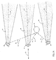
- an operator 30 when positioned in the operator's position 20 has a field of view which extends approximately 180° from the operators position toward the forward portion 12 of the vehicle. Further and by using the pair of side view mirrors 26, and the apparatus 10 the operator may, by looking along predetermined lines of sight, view areas beyond his normal field of view, and rearwardly of the operators position 20.
- the operator 30 has a first line of sight 31, which extends from the operator 30, to the apparatus 10 and which permits the operator to view rearwardly of the vehicle 11 and substantially along the longitudinal line of reference 23.
- the operator 30 further has a second line of sight 32 which extends from the operator to the left or operator's side view mirror 26 of the vehicle 11 and rearwardly thereof and which permits the operator 30 to view rearwardly of the overland vehicle along a line of sight which is substantially parallel to the longitudinal line of reference 23.
- the operator has a third line of sight 33 which extends from the operators position 20 to the passengers side view mirror 26 and rearwardly thereof. It similarly permits the operator to view along a line of sight which is substantially parallel to the longitudinal line of reference 23.
- Each of the respective lines of sight 31, 32 and 33 have a first component 34 which extends from the operator to the respective mirror; and a second component 35 which extends rearwardly of the vehicle.
- the individual mirrors 26 and the apparatus 10 each have respective illumination zones 36.
- the apparatus 10 includes a support member 40 having first and second ends 41 and 42 respectively, and wherein the first end 41 is fixed to a mounting bracket 43 which includes a pair of apertures 44, The apertures 44 are adapted to receive suitable fasteners such as screws or the like.
- the second end 42 is fixed to a swivel connector 45 in a manner which is well understood in the art.
- the mounting bracket has a substantially centrally disposed aperture 46 which is mounted in registry with a passageway 47 which is formed substantially centrally of the support member 40.
- An aperture 48 is formed in the swivel connector 46 and disposed in registry with the passageway 47.
- the swivel connector 45 is fixed to a housing or enclosure 50 and thereby permits the enclosure to be rotated into various positions relative to the operator's position 20 thereby positioning an accompanying mirror in selected positions to provide a field of view rearwardly of the overland vehicle 11 appropriate for the operator 30.
- the housing 50 has a top wall 51 which has formed therein an aperture 51A which is disposed in substantial registry with the aperture 48, a bottom wall 52, and a side wall 53 which joins the top and bottom walls together. As shown in Fig. 2, the sidewall 53 is narrowly rectangular and arcuately shaped, however it should be understood that other enclosure shapes will work with equal success and the final enclosure shape will be largely determined on aesthetic considerations.
- the individual wall members 51, 52 and 53 respectively have exterior or outside surfaces 54 and opposite inside surfaces 55 which define a cavity 60 of predetermined dimensions. Further the individual walls, in combination, define an aperture 61 which permits access to the cavity 60.
- a light source which is generally indicated by the numeral 70
- Three alternative light sources are shown which may be used with equal success. However, the invention is not limited to the three light sources discussed herein but may include other artificial light sources which have the characteristics which will be discussed in greater detail hereinafter.
- the light source 70 must be operable to produce wavelengths of light which are substantially "matched", that is, having wavelengths which are substantially identical to the peak wavelength transmittance characteristics of an associated dichroic mirror 110 and which is mounted on the enclosure 50 and disposed in substantially occluding relation relative to the aperture 61.
- the individual light sources are operable to produce artificial light having wavelengths which include the 600 through 700 nanometer band and which manifests itself by producing the color red.
- the invention is not limited to the peak wavelengths recited herein and may further be used with any number of wavelength combinations such that any visual spectrum colors can be seen.
- the individual light sources include first, second and third forms, 71, 72, and 73, respectively.
- the first form 71 of the light source 70 includes a bank of LEDs [light emitting diodes]; the second form 72 of the light source 70 includes a single lamp having a light bulb and suitable reflector; and the third form 73 includes a lamp support plate which is adapted to receive a plurality of automotive light bulbs 91.
- the first form 71 of the light source 70 includes a bank of LEDs which are individually mounted on a support plate 74 and which are adapted to produce artificial light having wavelengths which include the 600 through 700 nanometer band.
- Each of the respective LEDs have a beam center 76 which is individually oriented in substantially the same direction and which, in the form of the invention shown in Fig.
- Suitable electrical leads 78 would connect the bank of LEDS with the braking or signaling assembly of the vehicle not shown. The electrical leads would extend through the passageway 47 of the support member 40 to the appropriate signaling assembly.
- the second form 72 of the light source 70 is best seen by reference to Fig. 2 and may be used in place of the first form of the light source 71 and which was described earlier as a bank of LEDS.
- the second form includes a single bulb or lamp 81 which is mounted in or made integral with a suitable reflector 82.
- the lamp would be connected by suitable electrical leads 83 to the signaling assemblies of the vehicle such as, for example the braking system and wherein upon applying pressure to the brake pedal 25 the lamp would become energized.
- the lamp 80 has a beam center 84 which is similar in function to the beam centers described with respect to the first form of the light 71.
- the third form 73 of the light source 70 includes a synthetic lamp support plate 90 which is adapted to support a plurality of replaceable automotive bulbs or lamps 91.
- the lamp support plate has a plurality of apertures 93 which permits the individual replaceable lamps to be electrically coupled to the lamp support plate.
- the lamp support plate carries suitable etching on the reverse surface [not shown] which conducts electric current from appropriate electric leads 94 to the individual lamps.
- These lamps 91 similarly produce artificial light having wavelengths which include the wavelengths of 600 through 700 nanometers.
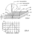
- a baffling assembly which is generally indicated by the numeral 100, includes a polycarbonate light control film which permits artificial light generated by the light source 70 to escape from the enclosure 50; the light emitted by the light source 70 traveling along the transmission path 77 and rearwardly of the overland vehicle 11 as best illustrated by reference to Fig. 1.
- the light control film 101 is a thin plastic film enclosing a plurality of closely spaced, black colored microlouvers.
- the light control film is approximately 0.75 millimeters (0.030 inches) thick, and the microlouvers are spaced approximately 0.127 millimeters (0.005 inches) apart.
- the microlouvers may be a transparent black or an opaque black, and further, the microlouvers may be positioned in various angles to provide a viewing angle, which may include angles as narrow as 48° ⁇ 6° or as wide as 90° ⁇ 15°. This is shown most clearly by reference to Fig. 4. It should be understood that the baffling assembly permits light emitted to escape within the viewing angle from the housing 50 and travel rearwardly of the vehicle 11 along the transmission path 77 and within the illumination zones, but further is operable to inhibit or block the light emitted by the light source 70 from traveling outside the viewing angle and along the first component 34 of the first line of sight 31 and into the view of the operator 30. This is best seen by reference to Figs. 1, 1A and 2. It should be apparent, therefor, that the operator may continue to use the apparatus 10 as a rearview mirror notwithstanding that artificial light is being emitted from same and is capable of being seen from a location rearwardly of the overland vehicle 11.
- the light control film 101 has a forward facing or front surface 102 and a back or rearward facing surface 103. Further, the light control film is defined by a peripheral edge 104, the light control film being adapted to closely fit the interior dimensions of the cavity as defined by the inside surface 55 of the walls 51, 52, and 53 respectively.
- the apparatus 10 includes a semi-transparent mirror 110.
- the semi-transparent mirror is a dichroic mirror which is adapted selectively to transmit and reflect light having predetermined wavelengths.
- the light source 70 is operable to produce artificial light having wavelengths of 600 through 700 nanometers which corresponds with the visible spectrum color red.
- the dichroic mirror 110 is operable to transmit the selected wavelengths of 600 through 700 nanometers thereby achieving several laudable benefits.
- a different dichroic mirror would be selected which would transmit the wavelengths corresponding with the color selected.
- the dichroic mirror 110 has a front or forward facing surface 111, a back or rearwardly facing surface 112, and a peripheral edge 113 which closely fits the cavity 60 of the enclosure 50 thereby substantially occluding the aperture 61. This construction essentially inhibits any light leakage from the light source 70 which is mounted internally of the housing 50.
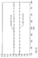
- Figs. 5, 6, and 7 demonstrate that a neutral, semi-transparent half-silvered mirror will not operate effectively for purposes of the present invention in view of optical characteristics inherent in its composition and structure. More particularly, Figs. 5 and 6 show the relationship of transmittance and reflectance as it relates to neutral half-silvered mirrors. In general, as the transmittance increases reflectance decreases, and vice versa. This relationship is shown by a comparative study of Figs. 5 and 6. Referring more particularly to Fig.
- this figure illustrates the characteristics of a neutral semi-transparent mirror which is capable of transmitting 58%, average, 600 through 700 nanometer wavelengths but is only capable of reflecting 37%, average, visible spectrum wavelengths.
- a neutral transparent mirror such as a half-silvered mirror
- the same mirror transmits only 20%, average, visible spectrum wavelengths.
- a more powerful lamp must be utilized in order to have the same effect with respect to signaling. Utilizing a more powerful lamp, of course, creates problems in terms of the production and accumulation of heat in the enclosure 50 and the related problem of the dissipation of same.
- the present invention addresses same by providing a dichroic mirror 110 which is substantially "matched" with the light source 70 and more particularly to the selected wavelengths of light produced by the light source, that is, the dichroic mirror is operable to transmit a large percentage of the selected wavelengths of artificial light while simultaneously retaining the ability to be an excellent reflector of ambient artificial and natural light.
- the dichroic mirror remains an excellent reflector, that is, achieving an average visible spectrum reflectance of 75%, while simultaneously achieving an average transmittance in the 600 through 700 nanometer band of 58%.
- the apparatus of the subject invention by utilizing a dichroic mirror substantially “matched” to the wavelengths of artificial light transmitted, becomes both an excellent reflector of ambient, visible spectrum light, as well as an excellent transmitter of artificial light emitted by light source 70. Further, and by utilizing a dichroic mirror 110 which is substantially “matched” to the wavelengths of light selected, the lower intensity light source 70 may be utilized thereby alleviating the problem related to the generation of heat within the enclosure 50.
- the dichroic mirror also operates to transmit the longer wavelengths of artificial light which generate heat energy thereby further inhibiting the generation and accumulation of heat within the enclosure 50.
- the apparatus 10 of the present invention includes a housing 50 having a cavity 60 and defining an aperture 61 wherein the housing 50 is mounted on the overland vehicle 11 in a location within a line of sight 31, 32, and/or 33 of an operator 30 who is positioned in the operator's position 20.
- the apparatus 10 of the subject invention further includes a light source 70 mounted in the housing 50, and which is positioned in the cavity 60, the light source 70 electrically coupled with a signaling assembly (not shown) which in turn is coupled with a directional signaling switch 27, or a switch (not shown) which is used in combination with the brake pedal 25.
- the light source 70 is energized thereby producing light having wavelengths which include the 600 through 700 nanometer band.
- the semi-transparent dichroic mirror 110 is mounted on the enclosure 50 and is disposed in substantially occluding relation relative to the aperture 60 and which is adapted substantially to reflect 75% [average] visible spectrum wavelengths and further is operable to transmit substantially 58% [average] wavelengths having 600 to 700 nanometers.
- a light control film 101 having a plurality of microlouvers 105 is positioned between the dichroic mirror 110 and the light source 70 and is adapted to direct or otherwise permit the escape of light emitted by the light source 70 from the housing 50 and along the transmission path 77 which is disposed in a position which is substantially parallel to the longitudinal line of reference 23 and rearwardly of the overland vehicle 11 such that it may be seen by the operators of adjacent overland vehicles travelling in close proximity thereto and within the illumination zone 36. Further the microlouvers are operable to substantially inhibit or block light emitted by the light source 70 from travelling along the first component 34 of the first line of sight 31 and into the operator's vision thereby detracting him.
Description
- The invention relates to a combined mirror and visual signaling apparatus comprising a housing with an aperture, a semi-transparent mirror substantially occluding the aperture, a light source mounted inside the housing, and a baffling assembly between the light source and the mirror, the baffling assembly having louvers which direct the light from the light source into a predetermined direction and which substantially inhibits the light from emanating in directions other than the predetermined direction. Such apparatus is known from GB-A-1.172.382 or AU-A-11.419/66.
- Combined signaling apparatus of the type referred to are used as outer rear mirrors for motor vehicles simultaneously used to signal intended turns or lane changes to the surrounding traffic and may be used as additional, "third" brake signal when used as interior mirror in an automobile.
- In the prior art combined mirror and visual signaling apparatus known from the above-referenced documents, the semi-transparent mirrors are neutral ones such as half-silver mirrors which do not have an average transmittance or an average visible spectrum reflectance which permit them to simultaneously be an excellent reflector and an excellent transmitter of light.
- It is accordingly an object underlying the invention to provide for a combined mirror and visual signaling apparatus which provides both a satisfactory view rearwards from an operators position and a satisfactory signaling effect to other traffic participants.
- According to the present invention this object is solved in that the mirror consists of a dichroic mirror.
- With such arrangement it is possible to adjust the characteristic of the light generated by the light source to the reflectance and transmittance characteristics of the dichroic mirror or, vice versa, so that satisfactory results are obtained in both respects.
- Preferred further developments and embodiments of the present invention are described in the sub-claims, the purposes and advantages whereof will become apparent from the further description.
- The invention will be further described with reference to the preferred embodiment shown in the drawings, in which:
- Fig. 1 is a plan view of the apparatus of the subject invention shown in an operative environment of an overland vehicle and wherein some underlying surfaces are illustrated in phantom lines for illustrative convenience.
- Fig. 1A is a schematic plan view of the apparatus of the subject invention shown in an operative environment, and wherein the surrounding supporting surfaces are removed for illustrative convenience.
- Fig. 2 is a perspective, exploded, side elevation view of the apparatus of the subject invention taken from a position along line 2-2 of Fig. 1.
- Fig. 3 is an enlarged, side elevation view of the light control film utilized in connection with the apparatus of the subject invention.
- Fig. 4 is a graphic illustration of the viewing angle, in degrees, as it relates to the percentage of transmission of the light control film shown in Fig. 3.
- Fig. 5 is a graphic illustration of the reflectance and transmittance of a neutral, semi-transparent mirror, such as a half-silvered mirror, and wherein the neutral, semi-transparent mirror has an average transmittance of approximately 58% and an average visible spectrum reflectance of 37%.
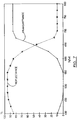
- Fig. 6 is a graphic illustration or the reflectance and transmittance of a neutral, semi-transparent mirror such as a half-silvered mirror, and wherein the average visible spectrum reflectance is approximately 75% and the average transmittance of light having wavelengths in the 600 through 700 nanometer band is approximately 20%.
- Fig. 7 is a graphic illustration of the reflectance and transmittance of the apparatus of the subject invention and wherein the apparatus includes a dichroic mirror which has an average visible spectrum reflectance of 75%, an average transmittance for light having wavelengths in the 600 through 700 nanometer band of approximately 58%, and greater than 90% transmittance for wavelengths greater than 700 nanometers.
- Referring more particularly to the drawings the visual signaling apparatus of the present invention is generally indicated by the
numeral 10 in Fig. 1. - For illustrative convenience the apparatus shown and described herein is discussed as it would be configured if it were installed on an overland vehicle 11 of conventional design and wherein the apparatus may be mounted on the vehicle, alternatively in place of the rearview mirror which is located in the passenger compartment, and/or in place of the side view mirrors which are mounted on the exterior surface of the vehicle. The
apparatus 10 is adapted to operate as a combination rearview mirror and visual signaling apparatus and wherein the visual signal it provides is capable of being seen from a position rearwardly of the overland vehicle 11 but which further cannot be seen by an operator of the same vehicle. - As best illustrated by reference to Fig. 1 the
visual signaling apparatus 10 of the subject invention is mounted on an overland vehicle 11 of conventional design having a front end orforward portion 12 and a rear end orportion 13. The overland vehicle 11 has a passenger compartment 14 which includes afront seat 15 and which further defines an operator'sposition 20. The overland vehicle 11 also includes front andrear windscreens reference 23, asteering wheel 24 and abrake pedal 25. A pair ofside view mirrors 26 are mounted on opposite sides of the overland vehicle and in a position exterior to the passenger compartment 14. The overland vehicle 11 further has a hand operateddirectional signaling switch 27 which is coupled with a directional signaling assembly [not shown], and which provides a visual signal which may alert drivers of other vehicles in the immediate vicinity that the overland vehicle 11 is about to change directions, turn, change lanes, etc. - As best illustrated by a comparison of Figs. 1 and 1A an
operator 30 when positioned in the operator'sposition 20 has a field of view which extends approximately 180° from the operators position toward theforward portion 12 of the vehicle. Further and by using the pair ofside view mirrors 26, and theapparatus 10 the operator may, by looking along predetermined lines of sight, view areas beyond his normal field of view, and rearwardly of theoperators position 20. In particular, and as best illustrated by reference to Fig. 1A, theoperator 30 has a first line ofsight 31, which extends from theoperator 30, to theapparatus 10 and which permits the operator to view rearwardly of the vehicle 11 and substantially along the longitudinal line ofreference 23. Theoperator 30 further has a second line ofsight 32 which extends from the operator to the left or operator'sside view mirror 26 of the vehicle 11 and rearwardly thereof and which permits theoperator 30 to view rearwardly of the overland vehicle along a line of sight which is substantially parallel to the longitudinal line ofreference 23. Furthermore, the operator has a third line ofsight 33 which extends from theoperators position 20 to the passengersside view mirror 26 and rearwardly thereof. It similarly permits the operator to view along a line of sight which is substantially parallel to the longitudinal line ofreference 23. Each of the respective lines ofsight first component 34 which extends from the operator to the respective mirror; and asecond component 35 which extends rearwardly of the vehicle. Further theindividual mirrors 26 and theapparatus 10 each haverespective illumination zones 36. These relationships are best seen by reference to Fig. 1. - The
apparatus 10, and which is best illustrated by reference to Fig. 2, includes asupport member 40 having first andsecond ends 41 and 42 respectively, and wherein the first end 41 is fixed to a mounting bracket 43 which includes a pair of apertures 44, The apertures 44 are adapted to receive suitable fasteners such as screws or the like. In addition, thesecond end 42 is fixed to aswivel connector 45 in a manner which is well understood in the art. The mounting bracket has a substantially centrally disposed aperture 46 which is mounted in registry with apassageway 47 which is formed substantially centrally of thesupport member 40. An aperture 48 is formed in the swivel connector 46 and disposed in registry with thepassageway 47. Theswivel connector 45 is fixed to a housing orenclosure 50 and thereby permits the enclosure to be rotated into various positions relative to the operator'sposition 20 thereby positioning an accompanying mirror in selected positions to provide a field of view rearwardly of the overland vehicle 11 appropriate for theoperator 30. Thehousing 50 has atop wall 51 which has formed therein anaperture 51A which is disposed in substantial registry with the aperture 48, abottom wall 52, and aside wall 53 which joins the top and bottom walls together. As shown in Fig. 2, thesidewall 53 is narrowly rectangular and arcuately shaped, however it should be understood that other enclosure shapes will work with equal success and the final enclosure shape will be largely determined on aesthetic considerations. Theindividual wall members outside surfaces 54 and opposite inside surfaces 55 which define acavity 60 of predetermined dimensions. Further the individual walls, in combination, define anaperture 61 which permits access to thecavity 60. - As best illustrated by reference to Fig. 2 a lighting means and which is herein illustrated as a light source which is generally indicated by the
numeral 70, is borne by thehousing 50 and mounted in thecavity 60 for purposes of emitting artificial light of predetermined wavelengths. Three alternative light sources are shown which may be used with equal success. However, the invention is not limited to the three light sources discussed herein but may include other artificial light sources which have the characteristics which will be discussed in greater detail hereinafter. It should be understood that notwithstanding thelight source 70 selected, the light source must be operable to produce wavelengths of light which are substantially "matched", that is, having wavelengths which are substantially identical to the peak wavelength transmittance characteristics of an associateddichroic mirror 110 and which is mounted on theenclosure 50 and disposed in substantially occluding relation relative to theaperture 61. In the present form of the invention the individual light sources are operable to produce artificial light having wavelengths which include the 600 through 700 nanometer band and which manifests itself by producing the color red. The invention is not limited to the peak wavelengths recited herein and may further be used with any number of wavelength combinations such that any visual spectrum colors can be seen. The individual light sources include first, second and third forms, 71, 72, and 73, respectively. - The
first form 71 of thelight source 70 includes a bank of LEDs [light emitting diodes]; the second form 72 of thelight source 70 includes a single lamp having a light bulb and suitable reflector; and thethird form 73 includes a lamp support plate which is adapted to receive a plurality ofautomotive light bulbs 91. Thefirst form 71 of thelight source 70 includes a bank of LEDs which are individually mounted on asupport plate 74 and which are adapted to produce artificial light having wavelengths which include the 600 through 700 nanometer band. Each of the respective LEDs have abeam center 76 which is individually oriented in substantially the same direction and which, in the form of the invention shown in Fig. 2, would normally be oriented in a direction wherein the artificial light produced from the individual LEDs would travel along atransmission path 77 which is disposed in substantially parallel relation relative to the longitudinal line ofreference 23 and rearwardly of the overland vehicle 11 such that it could be seen by another vehicle traveling in close proximity thereto and within theillumination zone 36. Suitableelectrical leads 78 would connect the bank of LEDS with the braking or signaling assembly of the vehicle not shown. The electrical leads would extend through thepassageway 47 of thesupport member 40 to the appropriate signaling assembly. - The second form 72 of the
light source 70 is best seen by reference to Fig. 2 and may be used in place of the first form of thelight source 71 and which was described earlier as a bank of LEDS. With respect to the second form of the light source 72, the second form includes a single bulb orlamp 81 which is mounted in or made integral with asuitable reflector 82. The lamp would be connected by suitableelectrical leads 83 to the signaling assemblies of the vehicle such as, for example the braking system and wherein upon applying pressure to thebrake pedal 25 the lamp would become energized. Thelamp 80 has abeam center 84 which is similar in function to the beam centers described with respect to the first form of thelight 71. - As best illustrated by reference to Fig. 2 the
third form 73 of thelight source 70 includes a syntheticlamp support plate 90 which is adapted to support a plurality of replaceable automotive bulbs orlamps 91. As best seen by reference to the drawings, the lamp support plate has a plurality ofapertures 93 which permits the individual replaceable lamps to be electrically coupled to the lamp support plate. The lamp support plate, of course, carries suitable etching on the reverse surface [not shown] which conducts electric current from appropriate electric leads 94 to the individual lamps. Theselamps 91 similarly produce artificial light having wavelengths which include the wavelengths of 600 through 700 nanometers. - A baffling assembly, which is generally indicated by the numeral 100, includes a polycarbonate light control film which permits artificial light generated by the
light source 70 to escape from theenclosure 50; the light emitted by thelight source 70 traveling along thetransmission path 77 and rearwardly of the overland vehicle 11 as best illustrated by reference to Fig. 1. Thelight control film 101 is a thin plastic film enclosing a plurality of closely spaced, black colored microlouvers. The light control film is approximately 0.75 millimeters (0.030 inches) thick, and the microlouvers are spaced approximately 0.127 millimeters (0.005 inches) apart. The microlouvers may be a transparent black or an opaque black, and further, the microlouvers may be positioned in various angles to provide a viewing angle, which may include angles as narrow as 48° ± 6° or as wide as 90° ± 15°. This is shown most clearly by reference to Fig. 4. It should be understood that the baffling assembly permits light emitted to escape within the viewing angle from thehousing 50 and travel rearwardly of the vehicle 11 along thetransmission path 77 and within the illumination zones, but further is operable to inhibit or block the light emitted by thelight source 70 from traveling outside the viewing angle and along thefirst component 34 of the first line ofsight 31 and into the view of theoperator 30. This is best seen by reference to Figs. 1, 1A and 2. It should be apparent, therefor, that the operator may continue to use theapparatus 10 as a rearview mirror notwithstanding that artificial light is being emitted from same and is capable of being seen from a location rearwardly of the overland vehicle 11. - The
light control film 101 has a forward facing orfront surface 102 and a back or rearward facingsurface 103. Further, the light control film is defined by aperipheral edge 104, the light control film being adapted to closely fit the interior dimensions of the cavity as defined by the inside surface 55 of thewalls - As best seen by reference to Fig. 2, the
apparatus 10 includes asemi-transparent mirror 110. The semi-transparent mirror is a dichroic mirror which is adapted selectively to transmit and reflect light having predetermined wavelengths. As earlierly discussed, thelight source 70 is operable to produce artificial light having wavelengths of 600 through 700 nanometers which corresponds with the visible spectrum color red. In the preferred embodiment, thedichroic mirror 110 is operable to transmit the selected wavelengths of 600 through 700 nanometers thereby achieving several laudable benefits. Of course, and should a different visible color be desired, then, in that event, a different dichroic mirror would be selected which would transmit the wavelengths corresponding with the color selected. Thedichroic mirror 110 has a front or forward facingsurface 111, a back or rearwardly facingsurface 112, and aperipheral edge 113 which closely fits thecavity 60 of theenclosure 50 thereby substantially occluding theaperture 61. This construction essentially inhibits any light leakage from thelight source 70 which is mounted internally of thehousing 50. - To best understand the advantages achieved by employing a
dichroic mirror 110 Figs. 5, 6, and 7 demonstrate that a neutral, semi-transparent half-silvered mirror will not operate effectively for purposes of the present invention in view of optical characteristics inherent in its composition and structure. More particularly, Figs. 5 and 6 show the relationship of transmittance and reflectance as it relates to neutral half-silvered mirrors. In general, as the transmittance increases reflectance decreases, and vice versa. This relationship is shown by a comparative study of Figs. 5 and 6. Referring more particularly to Fig. 5, this figure illustrates the characteristics of a neutral semi-transparent mirror which is capable of transmitting 58%, average, 600 through 700 nanometer wavelengths but is only capable of reflecting 37%, average, visible spectrum wavelengths. Similarly, and referring more particularly to Fig. 6, when a neutral transparent mirror, such as a half-silvered mirror is rendered operable to reflect 75% of the visible spectrum, the same mirror transmits only 20%, average, visible spectrum wavelengths. The relationship is clear, that is, as reflectance increases the corresponding ability of a neutral half-silvered mirror to transmit decreases, therefor in order to be a good reflector, the mirror, of necessity, must be a poor transmitter. If the mirror is a poor transmitter, then, in that event, a more powerful lamp must be utilized in order to have the same effect with respect to signaling. Utilizing a more powerful lamp, of course, creates problems in terms of the production and accumulation of heat in theenclosure 50 and the related problem of the dissipation of same. - In light of the above identified problems the present invention addresses same by providing a
dichroic mirror 110 which is substantially "matched" with thelight source 70 and more particularly to the selected wavelengths of light produced by the light source, that is, the dichroic mirror is operable to transmit a large percentage of the selected wavelengths of artificial light while simultaneously retaining the ability to be an excellent reflector of ambient artificial and natural light. By utilizing such a "matched" dichroic mirror, and as best understood by reference to Fig. 7, the dichroic mirror remains an excellent reflector, that is, achieving an average visible spectrum reflectance of 75%, while simultaneously achieving an average transmittance in the 600 through 700 nanometer band of 58%. Thus the apparatus of the subject invention, by utilizing a dichroic mirror substantially "matched" to the wavelengths of artificial light transmitted, becomes both an excellent reflector of ambient, visible spectrum light, as well as an excellent transmitter of artificial light emitted bylight source 70. Further, and by utilizing adichroic mirror 110 which is substantially "matched" to the wavelengths of light selected, the lowerintensity light source 70 may be utilized thereby alleviating the problem related to the generation of heat within theenclosure 50. The dichroic mirror also operates to transmit the longer wavelengths of artificial light which generate heat energy thereby further inhibiting the generation and accumulation of heat within theenclosure 50. - The operation of the described embodiment of the present invention is believed to be readily apparent and is briefly summarized at this point.
- As best illustrated by reference to Fig. 2 the
apparatus 10 of the present invention includes ahousing 50 having acavity 60 and defining anaperture 61 wherein thehousing 50 is mounted on the overland vehicle 11 in a location within a line ofsight operator 30 who is positioned in the operator'sposition 20. Theapparatus 10 of the subject invention further includes alight source 70 mounted in thehousing 50, and which is positioned in thecavity 60, thelight source 70 electrically coupled with a signaling assembly (not shown) which in turn is coupled with adirectional signaling switch 27, or a switch (not shown) which is used in combination with thebrake pedal 25. As should be understood, and upon activation of the signaling assembly, thelight source 70 is energized thereby producing light having wavelengths which include the 600 through 700 nanometer band. The semi-transparentdichroic mirror 110 is mounted on theenclosure 50 and is disposed in substantially occluding relation relative to theaperture 60 and which is adapted substantially to reflect 75% [average] visible spectrum wavelengths and further is operable to transmit substantially 58% [average] wavelengths having 600 to 700 nanometers. - A
light control film 101 having a plurality ofmicrolouvers 105 is positioned between thedichroic mirror 110 and thelight source 70 and is adapted to direct or otherwise permit the escape of light emitted by thelight source 70 from thehousing 50 and along thetransmission path 77 which is disposed in a position which is substantially parallel to the longitudinal line ofreference 23 and rearwardly of the overland vehicle 11 such that it may be seen by the operators of adjacent overland vehicles travelling in close proximity thereto and within theillumination zone 36. Further the microlouvers are operable to substantially inhibit or block light emitted by thelight source 70 from travelling along thefirst component 34 of the first line ofsight 31 and into the operator's vision thereby detracting him.
Claims (6)
- A combined mirror and visual signaling apparatus comprising- a housing (50) with an aperture (61),- a semi-transparent mirror (110) substantially occluding the aperture (61),- a light source (70) mounted inside the housing (50) which generates light of a predetermined band of wavelengths, and- a baffling assembly (100) between the light source (70) and the mirror (110), the baffling assembly (100) having louvers (102) which direct the light from the light source (70) into a predetermined direction and which substantially inhibits the light from emanating in directions other than the predetermined direction, characterized in that the semi-transparent mirror is dichroic and adapted to transmit light in said predetermined band of wavelengths.
- Apparatus according to claim 1, characterized in that the light source (70) comprises at least one lamp (75, 81, 91) having a beam center aligned with the predetermined direction.
- Apparatus according to claim 1, characterized in that the predetermined wavelengths band ranges from 600 to 700 nm.
- Apparatus according to claim 1 or 3, characterized in that the dichroic mirror (110) reflects 75% (average) visible spectrum wavelengths, and transmits substantially 58% (average) wavelengths.
- Apparatus according to claims 1 and 4, characterized in that the light source (70) emits light having wave lengths longer than those in the visible spectrum , and in that the longer wavelengths constitute radiant heat energy, and the mirror (110) is adapted to substantially transmit the longer wavelengths, thereby inhibiting production of heat within the housing (50).
- Apparatus according to any of the preceding claims, characterized in that the baffling assembly includes a light control film (101) having a plurality of substantially parallel, equally spaced microlouvers (105).
Applications Claiming Priority (2)
| Application Number | Priority Date | Filing Date | Title |
|---|---|---|---|
| US07/482,254 US5014167A (en) | 1990-02-20 | 1990-02-20 | Visual signaling apparatus |
| US482254 | 2000-01-13 |
Publications (2)
| Publication Number | Publication Date |
|---|---|
| EP0450162A1 EP0450162A1 (en) | 1991-10-09 |
| EP0450162B1 true EP0450162B1 (en) | 1994-10-12 |
Family
ID=23915347
Family Applications (1)
| Application Number | Title | Priority Date | Filing Date |
|---|---|---|---|
| EP90123437A Expired - Lifetime EP0450162B1 (en) | 1990-02-20 | 1990-12-06 | Visual signaling apparatus |
Country Status (5)
| Country | Link |
|---|---|
| US (2) | US5014167A (en) |
| EP (1) | EP0450162B1 (en) |
| JP (1) | JPH03248934A (en) |
| CA (1) | CA2028461C (en) |
| DE (1) | DE69013331T2 (en) |
Cited By (18)
| Publication number | Priority date | Publication date | Assignee | Title |
|---|---|---|---|---|
| US7688495B2 (en) | 2006-03-03 | 2010-03-30 | Gentex Corporation | Thin-film coatings, electro-optic elements and assemblies incorporating these elements |
| US7706046B2 (en) | 2004-06-08 | 2010-04-27 | Gentex Corporation | Rearview mirror element having a circuit mounted to the rear surface of the element |
| US7746534B2 (en) | 2006-12-07 | 2010-06-29 | Gentex Corporation | Thin-film coatings, electro-optic elements and assemblies incorporating these elements |
| US7830583B2 (en) | 2006-03-03 | 2010-11-09 | Gentex Corporation | Electro-optical element including IMI coatings |
| US7859737B2 (en) | 2002-09-20 | 2010-12-28 | Donnelly Corporation | Interior rearview mirror system for a vehicle |
| US7864398B2 (en) | 2004-06-08 | 2011-01-04 | Gentex Corporation | Electro-optical element including metallic films and methods for applying the same |
| US7864399B2 (en) | 2002-09-20 | 2011-01-04 | Donnelly Corporation | Reflective mirror assembly |
| US7898719B2 (en) | 2003-10-02 | 2011-03-01 | Donnelly Corporation | Rearview mirror assembly for vehicle |
| US8035881B2 (en) | 2007-03-05 | 2011-10-11 | Gentex Corporation | Multi-zone mirrors |
| US8169681B2 (en) | 2006-03-03 | 2012-05-01 | Gentex Corporation | Thin-film coatings, electro-optic elements and assemblies incorporating these elements |
| US8228590B2 (en) | 2010-08-09 | 2012-07-24 | Gentex Corporation | Electro-optic system configured to reduce a perceived color change |
| US8274729B2 (en) | 2006-03-03 | 2012-09-25 | Gentex Corporation | Thin-film coatings, electro-optic elements and assemblies incorporating these elements |
| US8368992B2 (en) | 2006-03-03 | 2013-02-05 | Gentex Corporation | Electro-optical element including IMI coatings |
| US8649083B2 (en) | 2007-03-05 | 2014-02-11 | Gentex Corporation | Multi-zone mirrors |
| US8964278B2 (en) | 2010-08-09 | 2015-02-24 | Gentex Corporation | Electro-optic system configured to reduce a perceived color change |
| US9346403B2 (en) | 2009-10-07 | 2016-05-24 | Magna Mirrors Of America, Inc. | Rearview mirror assembly |
| US9475431B2 (en) | 2011-10-05 | 2016-10-25 | Magna Mirrors Of America, Inc. | Rearview mirror assembly |
| US10261648B2 (en) | 2009-10-07 | 2019-04-16 | Magna Mirrors Of America, Inc. | Exterior rearview mirror assembly |
Families Citing this family (182)
| Publication number | Priority date | Publication date | Assignee | Title |
|---|---|---|---|---|
| US5014167A (en) * | 1990-02-20 | 1991-05-07 | K. W. Muth Company, Inc. | Visual signaling apparatus |
| US5481409A (en) * | 1990-02-20 | 1996-01-02 | K. W. Muth Company, Inc. | Mirror assembly |
| US5355284A (en) * | 1990-02-20 | 1994-10-11 | K. W. Muth Company, Inc. | Mirror assembly |
| US5361190A (en) * | 1990-02-20 | 1994-11-01 | K. W. Muth Co. Inc. | Mirror assembly |
| JP2570483Y2 (en) * | 1991-06-13 | 1998-05-06 | 忠男 田代 | Automotive turn signal device |
| US5290257A (en) * | 1992-01-02 | 1994-03-01 | Zhong Being Tang | Method and apparatus for de-airing the heart |
| DE4220499C2 (en) * | 1992-06-23 | 1998-06-04 | Daimler Benz Ag | Impact protection system with gas bag (airbag) |
| US5371659A (en) * | 1993-02-01 | 1994-12-06 | Donnelly Corporation | Remote-actuated exterior vehicle security light |
| US6176602B1 (en) * | 1993-02-01 | 2001-01-23 | Donnelly Corporation | Vehicle exterior mirror system with signal light |
| US5823654A (en) * | 1993-02-01 | 1998-10-20 | Donnelly Corporation | Universal exterior vehicle security light |
| US5497306A (en) * | 1993-02-01 | 1996-03-05 | Donnelly Corporation | Exterior vehicle security light |
| US6276821B1 (en) | 1992-12-16 | 2001-08-21 | Donnelly Corporation | Vehicle exterior mirror system with signal light |
| US5303130A (en) * | 1992-12-28 | 1994-04-12 | Wei Yung Feng | Illuminating automobile sideview mirror |
| EP0612826B1 (en) * | 1993-02-26 | 2000-10-04 | Donnelly Corporation | Electrochromic polymeric solid films, manufacturing electrochromic devices using such solid films, and processing for making such solid films and devices |
| US5910854A (en) | 1993-02-26 | 1999-06-08 | Donnelly Corporation | Electrochromic polymeric solid films, manufacturing electrochromic devices using such solid films, and processes for making such solid films and devices |
| EP0854370A1 (en) | 1993-12-07 | 1998-07-22 | K.W. Muth Company, Inc. | Mirror coating |
| US5528422A (en) * | 1993-12-07 | 1996-06-18 | K. W. Muth Company, Inc. | Mirror coating |
| US5436741A (en) * | 1993-12-28 | 1995-07-25 | Harman Automotive, Inc. | Holographic signaling mirror |
| US5668663A (en) | 1994-05-05 | 1997-09-16 | Donnelly Corporation | Electrochromic mirrors and devices |
| US6152588A (en) * | 1994-09-28 | 2000-11-28 | Sdl, Inc. | Addressable vehicular lighting system |
| US6019475A (en) * | 1994-09-30 | 2000-02-01 | Donnelly Corporation | Modular rearview mirror assembly including an electronic control module |
| US5539623A (en) * | 1994-10-12 | 1996-07-23 | General Signal Corporation | Lighting device used in an exit sign |
| US20120020101A1 (en) | 1994-11-02 | 2012-01-26 | Magna Mirrors Of America, Inc. | Vehicle exterior mirror system |
| US5669699A (en) * | 1994-11-02 | 1997-09-23 | Donnelly Corporation | Exterior vehicle security light |
| US5587699A (en) * | 1994-11-03 | 1996-12-24 | United Technologies Automotive Systems Inc. | Exterior mirror with information display |
| EP0725286A1 (en) | 1994-11-14 | 1996-08-07 | Optical Coating Laboratory, Inc. | Optical filter with neutral reflectance for visual signalling mirror |
| US5575552A (en) * | 1994-12-09 | 1996-11-19 | United Technologies Automotive Systems, Inc. | Lighted mirror apparatus |
| US5671996A (en) * | 1994-12-30 | 1997-09-30 | Donnelly Corporation | Vehicle instrumentation/console lighting |
| US5668675A (en) * | 1995-01-18 | 1997-09-16 | Fredricks; Ronald J. | Opto-electronic aid for alignment of exterior vehicle mirrors to minimize blind spot effects |
| US9586526B2 (en) | 1995-04-21 | 2017-03-07 | Magna Mirrors Of America, Inc. | Vehicle exterior mirror system |
| US6891563B2 (en) | 1996-05-22 | 2005-05-10 | Donnelly Corporation | Vehicular vision system |
| US5940120A (en) * | 1995-10-20 | 1999-08-17 | Prince Corporation | Vanity console |
| US5820245A (en) * | 1995-12-11 | 1998-10-13 | Donnelly Corporation | Rearview mirror assembly |
| US6000823A (en) | 1995-12-11 | 1999-12-14 | Donnelly Mirrors Limited | Rearview mirror assembly |
| US6045243A (en) | 1996-08-28 | 2000-04-04 | K.W. Muth Company, Inc. | Mirror assembly |
| US5788357A (en) * | 1996-08-28 | 1998-08-04 | K. W. Muth Company, Inc. | Mirror assembly |
| EP0845390A3 (en) * | 1996-11-29 | 2004-06-09 | Donnelly Corporation | Modular exterior rearview mirror assembly |
| DE29620775U1 (en) * | 1996-11-29 | 1998-03-26 | Hohe Gmbh & Co Kg | Outside mirrors for a vehicle |
| DE29621172U1 (en) * | 1996-12-06 | 1998-04-09 | Hohe Gmbh & Co Kg | Outside mirror with extended viewing angle |
| US5938320A (en) * | 1997-03-19 | 1999-08-17 | Harman Automotive, Inc. | Enhanced illuminated polymeric indicator employed in a mirror housing of an automotive vehicle |
| US6064525A (en) * | 1997-03-25 | 2000-05-16 | Glaverbel | Optical device including a dichromatic mirror |
| US6166848A (en) * | 1997-04-02 | 2000-12-26 | Gentex Corporation | Electrochromic rearview mirror incorporating a third surface metal reflector and a display/signal light |
| US6700692B2 (en) | 1997-04-02 | 2004-03-02 | Gentex Corporation | Electrochromic rearview mirror assembly incorporating a display/signal light |
| US6111683A (en) * | 1997-04-02 | 2000-08-29 | Gentex Corporation | Electrochromic mirrors having a signal light |
| US6356376B1 (en) * | 1997-04-02 | 2002-03-12 | Gentex Corporation | Electrochromic rearview mirror incorporating a third surface metal reflector and a display/signal light |
| US6441943B1 (en) | 1997-04-02 | 2002-08-27 | Gentex Corporation | Indicators and illuminators using a semiconductor radiation emitter package |
| US6111684A (en) * | 1997-04-02 | 2000-08-29 | Gentex Corporation | Electrochromic rearview mirror incorporating a third surface metal reflector and a display/signal light |
| US6124886A (en) | 1997-08-25 | 2000-09-26 | Donnelly Corporation | Modular rearview mirror assembly |
| US6250148B1 (en) | 1998-01-07 | 2001-06-26 | Donnelly Corporation | Rain sensor mount for use in a vehicle |
| US6326613B1 (en) | 1998-01-07 | 2001-12-04 | Donnelly Corporation | Vehicle interior mirror assembly adapted for containing a rain sensor |
| US8294975B2 (en) | 1997-08-25 | 2012-10-23 | Donnelly Corporation | Automotive rearview mirror assembly |
| US6172613B1 (en) | 1998-02-18 | 2001-01-09 | Donnelly Corporation | Rearview mirror assembly incorporating vehicle information display |
| FR2768895B1 (en) * | 1997-09-24 | 1999-12-10 | Valeo Electronique | LIGHT EMITTING DIODE CIRCUIT FOR MOTOR VEHICLE LIGHT AND MOTOR VEHICLE LIGHT COMPRISING SUCH A CIRCUIT |
| US6592230B2 (en) | 1997-10-16 | 2003-07-15 | Holland Hitch Company | Truck rearview mirror assembly having a display for displaying trailer coupling status information |
| US8288711B2 (en) | 1998-01-07 | 2012-10-16 | Donnelly Corporation | Interior rearview mirror system with forwardly-viewing camera and a control |
| US6445287B1 (en) | 2000-02-28 | 2002-09-03 | Donnelly Corporation | Tire inflation assistance monitoring system |
| US6329925B1 (en) | 1999-11-24 | 2001-12-11 | Donnelly Corporation | Rearview mirror assembly with added feature modular display |
| US6477464B2 (en) | 2000-03-09 | 2002-11-05 | Donnelly Corporation | Complete mirror-based global-positioning system (GPS) navigation solution |
| US6693517B2 (en) | 2000-04-21 | 2004-02-17 | Donnelly Corporation | Vehicle mirror assembly communicating wirelessly with vehicle accessories and occupants |
| US6005724A (en) * | 1998-10-05 | 1999-12-21 | K. W. Muth Company, Inc. | Mirror coating, mirror utilizing same, and a mirror assembly |
| US6076948A (en) * | 1998-10-28 | 2000-06-20 | K. W. Muth Company, Inc. | Electromagnetic radiation emitting or receiving assembly |
| US6595669B2 (en) | 1998-11-02 | 2003-07-22 | Code 3, Inc. | Vehicular warning light having less apparent color when not energized |
| CA2347799A1 (en) | 1998-11-02 | 2000-05-11 | Code 3, Inc. | Vehicular warning light having a dichroic element |
| US6262850B1 (en) | 1998-11-03 | 2001-07-17 | Cardinal Glass Industries, Inc. | Heat-treatable dichroic mirrors |
| US6292302B1 (en) | 1998-11-03 | 2001-09-18 | Cardinal Glass Industries, Inc. | Heat-treatable dichroic mirrors |
| US6257746B1 (en) | 1998-11-03 | 2001-07-10 | K. W. Muth Company, Inc. | Signalling assembly |
| US6428216B1 (en) * | 1998-11-09 | 2002-08-06 | John M. Savage, Jr. | Optical coupling of light pipes, with light diffusion |
| US6264353B1 (en) | 1998-11-23 | 2001-07-24 | Lear Automotive Dearborn, Inc. | Exterior mirror with supplement turn signal |
| DE19902487A1 (en) | 1999-01-22 | 2000-08-17 | Mekra Lang Gmbh & Co Kg | Rearview mirror |
| IT1307365B1 (en) * | 1999-03-25 | 2001-11-06 | Giovanni Manfre | REAR VIEW MIRROR WITH WIDE ANGLE OF VIEW AND REDUCED DISTORTION OF THE IMAGE, FOR VEHICLES. |
| US7009751B2 (en) * | 1999-05-14 | 2006-03-07 | Gentex Corporation | Electrochromic rearview mirror incorporating a third surface partially transmissive reflector |
| DE19922778A1 (en) | 1999-05-18 | 2000-11-23 | Mekra Lang Gmbh & Co Kg | Heated rearview mirror |
| US8066415B2 (en) | 1999-06-17 | 2011-11-29 | Magna Mirrors Of America, Inc. | Exterior mirror vision system for a vehicle |
| US6227689B1 (en) | 1999-09-28 | 2001-05-08 | Donnelly Corporation | Illumination device for exterior mirror |
| US7370983B2 (en) | 2000-03-02 | 2008-05-13 | Donnelly Corporation | Interior mirror assembly with display |
| WO2001064481A2 (en) | 2000-03-02 | 2001-09-07 | Donnelly Corporation | Video mirror systems incorporating an accessory module |
| US7855755B2 (en) | 2005-11-01 | 2010-12-21 | Donnelly Corporation | Interior rearview mirror assembly with display |
| US7167796B2 (en) | 2000-03-09 | 2007-01-23 | Donnelly Corporation | Vehicle navigation system for use with a telematics system |
| US6642840B2 (en) | 2000-07-28 | 2003-11-04 | Lang-Mekra North Amicica, Llc | Rearview mirror assembly with monitor |
| DE10036875A1 (en) | 2000-07-28 | 2002-02-28 | Mekra Lang Gmbh & Co Kg | Rearview mirror for vehicle, has monitor connected to camera which captures fields before, laterally and behind vehicle |
| JP3839237B2 (en) * | 2000-09-18 | 2006-11-01 | 株式会社小糸製作所 | Vehicle lighting |
| US6456194B1 (en) * | 2000-09-21 | 2002-09-24 | Craig D. Carlson | Device and method for sensing and indicating inclination of an automotive vehicle |
| US7581859B2 (en) | 2005-09-14 | 2009-09-01 | Donnelly Corp. | Display device for exterior rearview mirror |
| US7255451B2 (en) * | 2002-09-20 | 2007-08-14 | Donnelly Corporation | Electro-optic mirror cell |
| DE60220379T2 (en) | 2001-01-23 | 2008-01-24 | Donnelly Corp., Holland | IMPROVED VEHICLE LIGHTING SYSTEM |
| US6565239B2 (en) | 2001-02-27 | 2003-05-20 | Farlight, L.L.C. | Flush luminaire with optical element for angular intensity redistribution |
| DE20105791U1 (en) * | 2001-04-03 | 2002-08-14 | Mekra Lang Gmbh & Co Kg | Mirror arrangement for motor vehicles |
| US6657767B2 (en) * | 2001-05-21 | 2003-12-02 | Gentex Corporation | Rearview mirror assembly construction |
| US6650457B2 (en) * | 2001-05-21 | 2003-11-18 | Gentex Corporation | Rearview mirror constructed for efficient assembly |
| US6926431B1 (en) | 2002-04-09 | 2005-08-09 | Magna Donnelly Mirrors North America, L.L.C. | Vehicular mirror assembly incorporating multifunctional illumination source |
| DE10215854A1 (en) * | 2002-04-10 | 2003-10-23 | Mekra Lang Gmbh & Co Kg | Flashing light integrated into external mirror, especially for commercial vehicles, has light directing arrangement with mutually offset parallel vertical opaque strips on both sides of light panel |
| US6749325B2 (en) * | 2002-10-29 | 2004-06-15 | K.W. Muth Company | Signaling assembly |
| US7104676B2 (en) * | 2002-04-15 | 2006-09-12 | K.W. Muth Company, Inc. | Signaling assembly |
| US6918685B2 (en) | 2002-04-15 | 2005-07-19 | K. W. Muth Company, Inc. | Mirror with integrated signaling assembly |
| US6918674B2 (en) | 2002-05-03 | 2005-07-19 | Donnelly Corporation | Vehicle rearview mirror system |
| EP1514246A4 (en) | 2002-06-06 | 2008-04-16 | Donnelly Corp | Interior rearview mirror system with compass |
| US7329013B2 (en) | 2002-06-06 | 2008-02-12 | Donnelly Corporation | Interior rearview mirror system with compass |
| US20040000062A1 (en) * | 2002-06-28 | 2004-01-01 | Johnson Controls Technology Company | Compass display for a vehicle |
| WO2004103772A2 (en) | 2003-05-19 | 2004-12-02 | Donnelly Corporation | Mirror assembly for vehicle |
| US7184190B2 (en) * | 2002-09-20 | 2007-02-27 | Donnelly Corporation | Electro-optic reflective element assembly |
| US7360932B2 (en) * | 2004-06-01 | 2008-04-22 | Donnelly Corporation | Mirror assembly for vehicle |
| DE10256197A1 (en) * | 2002-12-02 | 2004-06-09 | Schefenacker Vision Systems Germany Gmbh & Co. Kg | Exterior rear view mirror for vehicles, in particular motor vehicles |
| US7121028B2 (en) | 2002-12-09 | 2006-10-17 | U-Haul International, Inc. | Method and apparatus for converting a rearview mirror into a dedicated information display |
| US20040145902A1 (en) * | 2003-01-28 | 2004-07-29 | Todd Daniel R. | Heated mirror assembly |
| US7221363B2 (en) * | 2003-02-12 | 2007-05-22 | Gentex Corporation | Vehicle information displays |
| US6958495B2 (en) * | 2003-03-20 | 2005-10-25 | Gentex Corporation | Mirror assembly with multi-color illumination |
| US7278766B2 (en) * | 2003-04-04 | 2007-10-09 | Honeywell International Inc. | LED based light guide for dual mode aircraft formation lighting |
| US7420756B2 (en) | 2003-05-20 | 2008-09-02 | Donnelly Corporation | Mirror reflective element |
| US20040264201A1 (en) * | 2003-06-30 | 2004-12-30 | Guide Corporation, A Delaware Corporation | Chromatic effect using light sources and condensing lenses |
| US20050068646A1 (en) * | 2003-09-25 | 2005-03-31 | Homedics, Inc. | Mirror with adjustable magnification and with a plurality of displays and devices |
| US7308341B2 (en) | 2003-10-14 | 2007-12-11 | Donnelly Corporation | Vehicle communication system |
| US7338177B2 (en) * | 2003-11-26 | 2008-03-04 | Donnelly Corporation | Mirror reflective element for a vehicle |
| US7008091B2 (en) | 2003-12-18 | 2006-03-07 | K.W. Muth Company, Inc. | Electromagnetic radiation assembly |
| US7452113B2 (en) | 2004-03-09 | 2008-11-18 | Gentex Corporation | Optics for controlling the direction of light rays and assemblies incorporating the optics |
| US7293901B2 (en) * | 2004-03-09 | 2007-11-13 | Gentex Corporation | Optics for controlling the direction of light rays and assemblies incorporating the optics |
| US20050242941A1 (en) * | 2004-04-29 | 2005-11-03 | Lance Chao | Third brake light of small-sized truck |
| US7306355B2 (en) * | 2004-07-13 | 2007-12-11 | Gentex Corporation | Optics for controlling the direction of light rays and assemblies incorporating the optics |
| US20060018047A1 (en) * | 2004-07-26 | 2006-01-26 | Todd Daniel R | Electromagnetic radiation assembly |
| US20060028815A1 (en) * | 2004-08-03 | 2006-02-09 | Triplex Manufacturing Company | Light assembly comprising integrated passive and active illumination sources |
| WO2006020697A2 (en) * | 2004-08-10 | 2006-02-23 | Cardinal Cg Company | Lcd mirror system and method |
| EP1625971B1 (en) * | 2004-08-13 | 2013-04-17 | Mazda Motor Corporation | Vehicle interior illumination structure |
| CN1740003B (en) * | 2004-08-13 | 2011-01-05 | 马自达汽车株式会社 | Vehicle interior illumination structure |
| US7400435B2 (en) * | 2005-01-19 | 2008-07-15 | Donnelly Corporation | Mirror assembly with heater element |
| US7241037B2 (en) * | 2005-03-23 | 2007-07-10 | K.W. Muth Company | Signaling assembly |
| US7626749B2 (en) | 2005-05-16 | 2009-12-01 | Donnelly Corporation | Vehicle mirror assembly with indicia at reflective element |
| US7327321B2 (en) * | 2005-06-27 | 2008-02-05 | K.W. Muth Company, Inc. | Electromagnetic radiation assembly |
| US11242009B2 (en) | 2005-07-06 | 2022-02-08 | Donnelly Corporation | Vehicular exterior mirror system with blind spot indicator |
| US11498487B2 (en) | 2005-07-06 | 2022-11-15 | Magna Mirrors Of America, Inc. | Vehicular exterior mirror system with blind spot indicator |
| WO2007005942A2 (en) | 2005-07-06 | 2007-01-11 | Donnelly Corporation | Vehicle exterior mirror assembly with blind spot indicator |
| DE102005036783B4 (en) * | 2005-08-02 | 2007-06-14 | Magna Donnelly Gmbh & Co.Kg | Rearview mirror for a vehicle |
| US7513668B1 (en) * | 2005-08-04 | 2009-04-07 | Rockwell Collins, Inc. | Illumination system for a head up display |
| US7192172B1 (en) * | 2005-09-08 | 2007-03-20 | K.W. Muth Company, Inc. | Visual warning device |
| US7273307B2 (en) * | 2005-10-25 | 2007-09-25 | K.W. Muth Company, Inc. | Signaling assembly |
| US7416318B2 (en) * | 2006-01-05 | 2008-08-26 | K.W. Muth Company, Inc. | Signaling assembly |
| CN101401024B (en) | 2006-03-09 | 2016-03-16 | 金泰克斯公司 | Comprise the vehicle rearview assembly of high intensity display |
| US20080024864A1 (en) * | 2006-07-28 | 2008-01-31 | K.W. Muth Company, Inc. | Signaling assembly |
| US7944371B2 (en) | 2007-11-05 | 2011-05-17 | Magna Mirrors Of America, Inc. | Exterior mirror with indicator |
| US11890991B2 (en) | 2006-10-24 | 2024-02-06 | Magna Mirrors Of America, Inc. | Vehicular exterior rearview mirror assembly with blind spot indicator element |
| US8058977B2 (en) | 2006-10-24 | 2011-11-15 | Donnelly Corporation | Exterior mirror having a display that can be viewed by a host driver or drivers of other vehicles |
| US7777611B2 (en) * | 2006-11-06 | 2010-08-17 | Donnelly Corporation | Display device for exterior rearview mirror |
| SE0700444L (en) * | 2007-02-16 | 2007-11-27 | Lars Svelander | ILLUMINATOR |
| US9274394B2 (en) | 2007-03-05 | 2016-03-01 | Gentex Corporation | Multi-zone mirrors |
| US10017847B2 (en) | 2007-03-05 | 2018-07-10 | Gentex Corporation | Method and apparatus for ion milling |
| US7748856B2 (en) | 2007-05-23 | 2010-07-06 | Donnelly Corporation | Exterior mirror element with integral wide angle portion |
| US8345345B2 (en) | 2007-06-27 | 2013-01-01 | Gentex Corporation | Electrochromic device having an improved fill port plug |
| US7884995B2 (en) * | 2007-06-27 | 2011-02-08 | Gentex Corporation | Electrochromic device having an improved fill port plug |
| US8786704B2 (en) | 2007-08-09 | 2014-07-22 | Donnelly Corporation | Vehicle mirror assembly with wide angle element |
| US8210724B2 (en) * | 2008-03-24 | 2012-07-03 | I/O Controls Corporation | Low glare lighting for a transit vehicle |
| US8154418B2 (en) | 2008-03-31 | 2012-04-10 | Magna Mirrors Of America, Inc. | Interior rearview mirror system |
| US7813023B2 (en) * | 2008-06-09 | 2010-10-12 | Magna Mirrors Of America, Inc. | Electro-optic mirror |
| US9487144B2 (en) | 2008-10-16 | 2016-11-08 | Magna Mirrors Of America, Inc. | Interior mirror assembly with display |
| US11498486B2 (en) | 2009-10-07 | 2022-11-15 | Magna Mirrors Of America, Inc. | Vehicular exterior rearview mirror assembly |
| EP2314404B1 (en) * | 2009-10-22 | 2012-06-20 | Klingelnberg AG | Method for hard fine processing of the tooth flanks of a gear wheel |
| US9205780B2 (en) | 2010-02-04 | 2015-12-08 | Magna Mirrors Of America, Inc. | Electro-optic rearview mirror assembly for vehicle |
| US9481304B2 (en) | 2010-05-24 | 2016-11-01 | Magna Mirrors Of America, Inc. | Automotive exterior mirror heater control |
| US8770810B2 (en) | 2010-12-10 | 2014-07-08 | Smr Patents S.A.R.L. | Rear view mirror assembly with optical indicator |
| US20120280528A1 (en) * | 2011-05-06 | 2012-11-08 | Ford Global Technologies, Llc | Vehicle accent molding with puddle light |
| US8988755B2 (en) | 2011-05-13 | 2015-03-24 | Magna Mirrors Of America, Inc. | Mirror reflective element |
| DE102011103202B4 (en) * | 2011-05-31 | 2014-08-28 | SMR Patents S.à.r.l. | Außenspiegelset |
| US8736940B2 (en) | 2011-09-30 | 2014-05-27 | Magna Mirrors Of America, Inc. | Exterior mirror with integral spotter mirror and method of making same |
| US8801245B2 (en) | 2011-11-14 | 2014-08-12 | Magna Mirrors Of America, Inc. | Illumination module for vehicle |
| US9458979B2 (en) * | 2012-12-14 | 2016-10-04 | Sl Corporation | Signal lamp for vehicle having a light guide and mirror housing and lamp housing with reflection unit and support unit |
| WO2014110124A1 (en) | 2013-01-09 | 2014-07-17 | Gentex Corporation | Printed appliqué and method thereof |
| US9216691B2 (en) | 2013-02-25 | 2015-12-22 | Magna Mirrors Of America, Inc. | Exterior mirror with spotter mirror |
| US9057925B2 (en) | 2013-03-15 | 2015-06-16 | Gentex Corporation | Fill port plugs for electrochromic devices |
| US9174578B2 (en) | 2013-04-22 | 2015-11-03 | Magna Mirrors Of America, Inc. | Interior rearview mirror assembly |
| US9815409B2 (en) | 2013-05-09 | 2017-11-14 | Magna Mirrors Of America, Inc. | Rearview vision system for vehicle |
| KR101766635B1 (en) | 2013-09-24 | 2017-08-09 | 젠텍스 코포레이션 | Display mirror assembly |
| US11086207B2 (en) * | 2013-10-03 | 2021-08-10 | Autodesk, Inc. | Reflection-based target selection on large displays with zero latency feedback |
| US9454054B2 (en) | 2013-11-18 | 2016-09-27 | Magna Mirrors Of America, Inc. | Electro-optic mirror element and process of making same |
| US11235699B2 (en) | 2014-02-07 | 2022-02-01 | Magna Mirrors Of America, Inc. | Illumination module for vehicle |
| US9663027B2 (en) | 2014-02-19 | 2017-05-30 | Fico Mirrors, S.A. | Exterior rear view mirror assembly for a motor vehicle |
| US9761144B2 (en) | 2014-09-11 | 2017-09-12 | Magna Mirrors Of America, Inc. | Exterior mirror with blind zone indicator |
| US9776569B2 (en) | 2015-01-30 | 2017-10-03 | Magna Mirrors Of America, Inc. | Exterior mirror with heater pad |
| US20180134217A1 (en) | 2015-05-06 | 2018-05-17 | Magna Mirrors Of America, Inc. | Vehicle vision system with blind zone display and alert system |
| WO2016187215A1 (en) * | 2015-05-18 | 2016-11-24 | Gentex Corporation | Full display rearview device |
| DE102015008715B3 (en) * | 2015-07-06 | 2016-12-22 | Audi Ag | Exterior mirror unit for a vehicle |
| US9659498B2 (en) | 2015-09-28 | 2017-05-23 | Magna Mirrors Of America, Inc. | Exterior mirror assembly with blind zone indicator |
| CN105774660B (en) * | 2016-03-11 | 2019-03-12 | 深圳市歌美迪电子技术发展有限公司 | A kind of band uniformly enhances backlit display screen rear-view mirror system |
| US11035609B2 (en) * | 2016-11-07 | 2021-06-15 | Carrier Corporation | Edge fluorescing acrylic light bar display for transportation refrigeration units |
| US10679480B2 (en) | 2018-03-22 | 2020-06-09 | Paul L. Eckert | Event indicator system |
| CN110871733B (en) * | 2018-08-29 | 2022-08-02 | 长城汽车股份有限公司 | Vehicle brake lamp control method, device and system and readable storage medium thereof |
Family Cites Families (29)
| Publication number | Priority date | Publication date | Assignee | Title |
|---|---|---|---|---|
| GB268359A (en) * | 1926-03-24 | 1927-07-28 | Gilbert Avril | Novel or improved combined rear reflecting mirror and signalling apparatus for use more especially on motor vehicles |
| US2060401A (en) * | 1935-05-25 | 1936-11-10 | Joseph C Smith | Direction signal |
| US2190123A (en) * | 1938-07-02 | 1940-02-13 | Stephen C Pace | Lighting signal |
| US2263382A (en) * | 1939-06-19 | 1941-11-18 | Gotzinger George | Mirror signal |
| US2580014A (en) * | 1949-09-13 | 1951-12-25 | Gazda Antoine | Combined rearview mirror and direction indicating device |
| US2595331A (en) * | 1950-01-30 | 1952-05-06 | Paul F Calihan | Combination vision mirror and signaling device |
| US3266016A (en) * | 1964-08-06 | 1966-08-09 | Maru Sho | Outside signal for automobiles |
| AU415830B2 (en) * | 1966-09-21 | 1971-08-02 | Vehicle accessories | |
| GB1172382A (en) * | 1966-11-23 | 1969-11-26 | Shigeru Maruyama | A Vehicle Rear-View Mirror Combined with a Flashing Turn Indicator |
| US3436758A (en) * | 1967-02-23 | 1969-04-01 | Klaus Kluth | Vehicular warning device having spring positioned reflecting member |
| US3543018A (en) * | 1968-08-06 | 1970-11-24 | Gen Motors Corp | Rearview mirror with map light |
| US3665392A (en) * | 1970-08-24 | 1972-05-23 | John T Annas | Vehicle driver-actuated safety signal light assembly |
| US4040726A (en) * | 1976-03-12 | 1977-08-09 | Paca Francis B | See-through mirror with spaced reflective strips |
| GB2099628B (en) * | 1981-04-07 | 1984-11-14 | Nippon Denso Co | Electroluminescent device combined with mirror |
| US4588267A (en) * | 1984-01-18 | 1986-05-13 | Ronald Pastore | Combination rear view mirror and digital clock |
| JPS60193738A (en) * | 1984-03-15 | 1985-10-02 | Nissan Motor Co Ltd | Lighting device for vehicle |
| US4646210A (en) * | 1984-06-20 | 1987-02-24 | Donnelly Corporation | Vehicular mirror and light assembly |
| US4516197A (en) * | 1984-08-09 | 1985-05-07 | Yonkers Edward H | Antiglare panel |
| US4630904A (en) * | 1985-01-22 | 1986-12-23 | Ronald Pastore | Combination rear view mirror and digital displays |
| US4807096A (en) * | 1986-06-26 | 1989-02-21 | Donnelly Corporation | Interior light/carrier module for vehicles |
| US4733336A (en) * | 1986-06-26 | 1988-03-22 | Donnelly Corporation | Lighted/information case assembly for rearview mirrors |
| US4793690A (en) * | 1986-07-18 | 1988-12-27 | Donnelly Corporation | Rearview mirror control circuit |
| US4917477A (en) * | 1987-04-06 | 1990-04-17 | Gentex Corporation | Automatic rearview mirror system for automotive vehicles |
| IE59698B1 (en) * | 1987-04-08 | 1994-03-23 | Donnelly Mirrors Ltd | Rearview mirror control circuit |
| US4799768A (en) * | 1987-04-27 | 1989-01-24 | Donnelly Corporation | Automatic rearview mirror with filtered light sensors |
| DE3720848A1 (en) * | 1987-06-24 | 1989-01-05 | Bosch Gmbh Robert | Display device in motor vehicles |
| US4791534A (en) * | 1987-08-07 | 1988-12-13 | Lindberg Victor L | Vehicle including substantially transparent high mounted stop light |
| US4882565A (en) * | 1988-03-02 | 1989-11-21 | Donnelly Corporation | Information display for rearview mirrors |
| US5014167A (en) * | 1990-02-20 | 1991-05-07 | K. W. Muth Company, Inc. | Visual signaling apparatus |
-
1990
- 1990-02-20 US US07/482,254 patent/US5014167A/en not_active Expired - Lifetime
- 1990-10-23 CA CA002028461A patent/CA2028461C/en not_active Expired - Fee Related
- 1990-11-08 JP JP2301265A patent/JPH03248934A/en active Pending
- 1990-12-06 EP EP90123437A patent/EP0450162B1/en not_active Expired - Lifetime
- 1990-12-06 DE DE69013331T patent/DE69013331T2/en not_active Expired - Fee Related
-
1991
- 1991-05-02 US US07/694,884 patent/US5207492A/en not_active Expired - Lifetime
Cited By (21)
| Publication number | Priority date | Publication date | Assignee | Title |
|---|---|---|---|---|
| US7864399B2 (en) | 2002-09-20 | 2011-01-04 | Donnelly Corporation | Reflective mirror assembly |
| US7859737B2 (en) | 2002-09-20 | 2010-12-28 | Donnelly Corporation | Interior rearview mirror system for a vehicle |
| US7898719B2 (en) | 2003-10-02 | 2011-03-01 | Donnelly Corporation | Rearview mirror assembly for vehicle |
| US7864398B2 (en) | 2004-06-08 | 2011-01-04 | Gentex Corporation | Electro-optical element including metallic films and methods for applying the same |
| US7706046B2 (en) | 2004-06-08 | 2010-04-27 | Gentex Corporation | Rearview mirror element having a circuit mounted to the rear surface of the element |
| US7830583B2 (en) | 2006-03-03 | 2010-11-09 | Gentex Corporation | Electro-optical element including IMI coatings |
| US8547622B2 (en) | 2006-03-03 | 2013-10-01 | Gentex Corporation | Thin-film coatings, electro-optic elements and assemblies incorporating these elements |
| US9529214B2 (en) | 2006-03-03 | 2016-12-27 | Gentex Corporation | Thin-film coatings, electro-optic elements and assemblies incorporating these elements |
| US8169681B2 (en) | 2006-03-03 | 2012-05-01 | Gentex Corporation | Thin-film coatings, electro-optic elements and assemblies incorporating these elements |
| US7688495B2 (en) | 2006-03-03 | 2010-03-30 | Gentex Corporation | Thin-film coatings, electro-optic elements and assemblies incorporating these elements |
| US8274729B2 (en) | 2006-03-03 | 2012-09-25 | Gentex Corporation | Thin-film coatings, electro-optic elements and assemblies incorporating these elements |
| US8368992B2 (en) | 2006-03-03 | 2013-02-05 | Gentex Corporation | Electro-optical element including IMI coatings |
| US7746534B2 (en) | 2006-12-07 | 2010-06-29 | Gentex Corporation | Thin-film coatings, electro-optic elements and assemblies incorporating these elements |
| US8649083B2 (en) | 2007-03-05 | 2014-02-11 | Gentex Corporation | Multi-zone mirrors |
| US8035881B2 (en) | 2007-03-05 | 2011-10-11 | Gentex Corporation | Multi-zone mirrors |
| US9346403B2 (en) | 2009-10-07 | 2016-05-24 | Magna Mirrors Of America, Inc. | Rearview mirror assembly |
| US10261648B2 (en) | 2009-10-07 | 2019-04-16 | Magna Mirrors Of America, Inc. | Exterior rearview mirror assembly |
| US8508832B2 (en) | 2010-08-09 | 2013-08-13 | Gentex Corporation | Electro-optic system configured to reduce a perceived color change |
| US8228590B2 (en) | 2010-08-09 | 2012-07-24 | Gentex Corporation | Electro-optic system configured to reduce a perceived color change |
| US8964278B2 (en) | 2010-08-09 | 2015-02-24 | Gentex Corporation | Electro-optic system configured to reduce a perceived color change |
| US9475431B2 (en) | 2011-10-05 | 2016-10-25 | Magna Mirrors Of America, Inc. | Rearview mirror assembly |
Also Published As
| Publication number | Publication date |
|---|---|
| US5207492A (en) | 1993-05-04 |
| DE69013331D1 (en) | 1994-11-17 |
| CA2028461A1 (en) | 1991-08-21 |
| US5014167A (en) | 1991-05-07 |
| EP0450162A1 (en) | 1991-10-09 |
| DE69013331T2 (en) | 1995-02-16 |
| JPH03248934A (en) | 1991-11-06 |
| CA2028461C (en) | 1994-11-08 |
Similar Documents
| Publication | Publication Date | Title |
|---|---|---|
| EP0450162B1 (en) | Visual signaling apparatus | |
| EP0694000B1 (en) | Mirror assembly | |
| CA2129257C (en) | A mirror assembly having means for emitting or receiving a predetermined narrow spectral band of light | |
| US5788357A (en) | Mirror assembly | |
| CA2338373C (en) | Mirror assembly | |
| MX2007016560A (en) | Electromagnetic radiation assembly. | |
| US6749325B2 (en) | Signaling assembly | |
| US7008091B2 (en) | Electromagnetic radiation assembly | |
| CA2556908A1 (en) | Signaling assembly | |
| JPS61188242A (en) | Door mirror | |
| US20060018047A1 (en) | Electromagnetic radiation assembly |
Legal Events
| Date | Code | Title | Description |
|---|---|---|---|
| PUAI | Public reference made under article 153(3) epc to a published international application that has entered the european phase |
Free format text: ORIGINAL CODE: 0009012 |
|
| AK | Designated contracting states |
Kind code of ref document: A1 Designated state(s): DE FR GB IT |
|
| 17P | Request for examination filed |
Effective date: 19911114 |
|
| 17Q | First examination report despatched |
Effective date: 19930416 |
|
| GRAA | (expected) grant |
Free format text: ORIGINAL CODE: 0009210 |
|
| AK | Designated contracting states |
Kind code of ref document: B1 Designated state(s): DE FR GB IT |
|
| REF | Corresponds to: |
Ref document number: 69013331 Country of ref document: DE Date of ref document: 19941117 |
|
| ET | Fr: translation filed | ||
| ITF | It: translation for a ep patent filed |
Owner name: BUGNION S.P.A. |
|
| PLBE | No opposition filed within time limit |
Free format text: ORIGINAL CODE: 0009261 |
|
| STAA | Information on the status of an ep patent application or granted ep patent |
Free format text: STATUS: NO OPPOSITION FILED WITHIN TIME LIMIT |
|
| 26N | No opposition filed | ||
| REG | Reference to a national code |
Ref country code: GB Ref legal event code: IF02 |
|
| PGFP | Annual fee paid to national office [announced via postgrant information from national office to epo] |
Ref country code: IT Payment date: 20071220 Year of fee payment: 18 |
|
| PGFP | Annual fee paid to national office [announced via postgrant information from national office to epo] |
Ref country code: GB Payment date: 20071219 Year of fee payment: 18 |
|
| PGFP | Annual fee paid to national office [announced via postgrant information from national office to epo] |
Ref country code: DE Payment date: 20080228 Year of fee payment: 18 |
|
| PGFP | Annual fee paid to national office [announced via postgrant information from national office to epo] |
Ref country code: FR Payment date: 20071214 Year of fee payment: 18 |
|
| GBPC | Gb: european patent ceased through non-payment of renewal fee |
Effective date: 20081206 |
|
| REG | Reference to a national code |
Ref country code: FR Ref legal event code: ST Effective date: 20090831 |
|
| PG25 | Lapsed in a contracting state [announced via postgrant information from national office to epo] |
Ref country code: DE Free format text: LAPSE BECAUSE OF NON-PAYMENT OF DUE FEES Effective date: 20090701 |
|
| PG25 | Lapsed in a contracting state [announced via postgrant information from national office to epo] |
Ref country code: GB Free format text: LAPSE BECAUSE OF NON-PAYMENT OF DUE FEES Effective date: 20081206 |
|
| PG25 | Lapsed in a contracting state [announced via postgrant information from national office to epo] |
Ref country code: FR Free format text: LAPSE BECAUSE OF NON-PAYMENT OF DUE FEES Effective date: 20081231 |
|
| PG25 | Lapsed in a contracting state [announced via postgrant information from national office to epo] |
Ref country code: IT Free format text: LAPSE BECAUSE OF NON-PAYMENT OF DUE FEES Effective date: 20081206 |