EP0454571A1 - Identification and checking seal - Google Patents
Identification and checking seal Download PDFInfo
- Publication number
- EP0454571A1 EP0454571A1 EP91401080A EP91401080A EP0454571A1 EP 0454571 A1 EP0454571 A1 EP 0454571A1 EP 91401080 A EP91401080 A EP 91401080A EP 91401080 A EP91401080 A EP 91401080A EP 0454571 A1 EP0454571 A1 EP 0454571A1
- Authority
- EP
- European Patent Office
- Prior art keywords
- link
- seal according
- male
- plate
- female
- Prior art date
- Legal status (The legal status is an assumption and is not a legal conclusion. Google has not performed a legal analysis and makes no representation as to the accuracy of the status listed.)
- Withdrawn
Links
Images

Classifications
-
- G—PHYSICS
- G09—EDUCATION; CRYPTOGRAPHY; DISPLAY; ADVERTISING; SEALS
- G09F—DISPLAYING; ADVERTISING; SIGNS; LABELS OR NAME-PLATES; SEALS
- G09F3/00—Labels, tag tickets, or similar identification or indication means; Seals; Postage or like stamps
- G09F3/02—Forms or constructions
- G09F3/03—Forms or constructions of security seals
- G09F3/0305—Forms or constructions of security seals characterised by the type of seal used
- G09F3/0347—Forms or constructions of security seals characterised by the type of seal used having padlock-type sealing means
- G09F3/0352—Forms or constructions of security seals characterised by the type of seal used having padlock-type sealing means using cable lock
-
- G—PHYSICS
- G09—EDUCATION; CRYPTOGRAPHY; DISPLAY; ADVERTISING; SEALS
- G09F—DISPLAYING; ADVERTISING; SIGNS; LABELS OR NAME-PLATES; SEALS
- G09F3/00—Labels, tag tickets, or similar identification or indication means; Seals; Postage or like stamps
- G09F3/02—Forms or constructions
- G09F3/03—Forms or constructions of security seals
- G09F3/0305—Forms or constructions of security seals characterised by the type of seal used
- G09F3/037—Forms or constructions of security seals characterised by the type of seal used having tie-wrap sealing means
Definitions
- the present invention relates to an identification and control seal.
- the seal according to the invention finds a particular but nonlimiting use as an identification and control bracelet for slaughtered game.
- bracelets It is known for hunting certain types of game to distribute bracelets in a determined number corresponding to the number of pieces of game that can be killed, this in order to ensure the sustainability of the species.
- the bracelets are intended to be fixed inviolably on a leg or a tendon or on the neck of the killed game.
- the bracelets are formed in a known manner of a flexible link whose ends must be secured by a seal once placed on the game.
- the present invention aims to overcome this drawback by proposing an identification and control seal avoiding multiple uses.
- Another object of the seal according to the invention is to ensure an inviolable and rapid closure. Yet another purpose of the seal is to make the identification of the object or animal on which it is placed easy and secure.
- the seal according to the invention is provided with at least one marking plate, with a link, and with means for closing the loop formed by said link and is essentially characterized in that the link is integral detachably over all or part of its length from the marking plate, in that it comprises at one of its ends a male or female part of the closing means and is fixedly secured to the plate at a point distant from its end carrying said male or female part.
- the identification and control seal comprises at least one marking plate 1 on which certain inscriptions can be made, a link 2 intended to form a loop for attaching the seal to object or animal and means of closure inviolable of the loop formed by the link 2.
- the seal is provided with a single marking plate 1.
- the closing means comprise a male part 3 and a female part 4 intended to cooperate in closing with each other to keep the loop formed by the link 2 closed.
- the link 2 of the seal according to the invention is detachably secured over all or part of its length of the marking plate 1, has at one of its ends the male part 3 or female 4 of the closure means and is secured so fixed of the marking plate 1 at a point distant along its length from the end carrying the said male or female part.
- the end of the link 2 not carrying the male or female part of the closure means is fixedly secured to the marking plate 1.
- the other part of the closure means is integral in a non-detachable manner with the marking plate.
- the link 2 is detachably secured to the marking plate over all or part of its length from its end carrying the male part 3 or female 4 of the closure means.
- the link 2 is detachably secured to the plate 1 over its entire length and on the periphery of said plate.
- the connection 2 to the marking plate 1 is secured by a plurality of weak points 5 established over the entire length of the link 2 and on the periphery of the plate 1 and breaking under the effect of a traction.
- One of the ends of the link 2 carries the male 3 or female 4 part of the closure means which is also detachably secured to the marking plate 1.
- the loop can be formed and then closed by cooperation of the male 3 and female 4 parts.
- the link 2 can be secured to the plate 1 detachably only over part of its length but from its end carrying the male part 3 or female 4 of the closure means.
- the rupture of the points of weakness 5 formed from this end also constitutes a presumption of use of the seal.
- the end of the detachable link 2 carries the male part 3 of the closing means, the female part 4 being secured in a non-detachable manner to the marking plate 1 but it goes without saying that the reverse can be achieved.
- the male part 3 of the closure means comprises a base 6, on which are projecting two parallel tabs 7 spaced from one another and each having on their outer face a barb 8 .
- the faces of the legs 7 facing each other are divergent at the ends of said legs.
- the latter are preferably slightly elastic.
- the base 6 is preferably in the form of a disc and the link 2 is fixed there radially.
- the female part 4 of the closing means as shown in FIGS. 1 and 2 is constituted by a cube 9 fixed to the marking plate 1 so as to be projecting with respect to a face of the plate.
- This cube 9 is preferably fixed at the periphery of the plate 1.
- a housing 10 passing right through it and preferably opening onto the faces of said cube parallel to the plate 1.
- the housing 10 is intended to receive the tabs 7 of the male part and to retain the latter irremovably.
- two parallel faces of the housing 10 are provided each of a shoulder 11 on which the barbs 8 of the tabs 7 are clipped, thus preventing the withdrawal of the male part 3.
- the shoulders 11 are produced obliquely so that the barbs 8 come to bear by their surface thereon.
- the angle of inclination of the barbs 8 and the shoulders 11 is the same.
- the housing 10 is provided in its entry area of the male part 3 with a central partition 12 formed parallel to the faces provided with the shoulders 11. This partition 12 is intended to be placed between the tabs 7 of the male part 3 to center and guide the latter in order to ensure correct and irremovable closure.
- the housing 10 of the cube 9 is obstructed by a cover 13 fixed in a non-removable manner in a recess 14 formed on the face of the cube 9 parallel to that provided with the inlet of the housing 10.
- the cover 13 is fixed in the recess 14 by any known means and preferably by welding and so that it cannot be removed.
- this female part 4 of the closing means is made all the easier by the presence of this cover 13.
- Said cover is provided on its inner face to the housing 10 with a holding element for spacing the tabs 7 of the male part.
- This spacing holding element consists of a wedge-shaped projection 15 intended to be placed in the extension of the partition 12 and to keep the legs apart. 7 of the male part so that the barbs 8 thereof are held against the shoulders 11 of the housing 10.
- the legs 7 come into contact with the conical projection 15 by the diverging ends of their opposite face. Due to the cooperation of the barbs 8 with the shoulders 11, the wedge-shaped projection 15 keeping the legs 7 apart and the inaccessibility inside the housing 10, the means for closing the seal according to the invention are inviolable.
- a countersink (not shown) in which is housed the base 6 of the male part 3 so that said base is not protruding on the cube 9 and therefore n 'offer no grip on a tool for an attempt to break the seal closing means.
- the base 6 may have a contour which follows the shape of a square.
- the link 2 attaching laterally to the base, it will be made in the bead defining the counterbore, a notch for the passage of the link.
- the female part 4 of said closing means is formed on the periphery of the marking plate 1.
- the link 2 is integral in a non-detachable manner by one of its ends of said female part while the other end of said link carries the male part 3.
- Said male part is detachably secured to the female part 4 by means of a point of weakness 5.
- the separation of the link 2 is done first by breaking the weak point 5 between the male part 3 and the female part 4 then by breaking the other weak points 5 between the said link and the periphery of the plate 1, the part male 3 which can then cooperate in closing with the female part 4 thus locking the loop formed by the link 2.
- the marking plate 1 of the seal according to the invention is equipped with at least one detachable area 16 which can receive an inscription and a non-detachable surface also receiving inscriptions.
- said marking plate is provided with means making it possible to determine a date.
- These means are constituted by detachable zones 16, for example, the number of 6 defining a month and by studs 17 formed at the periphery of the plate and for example the number of 31 defining the days.
- Said pads are preferably circular, thus giving the plate 1 a scalloped edge.
- these circular studs allow the attachment at a point of the link 2.
- the latter is detachably fixed to the plate 1 by points of weakness 5 established between itself and the studs 17.
- studs 17 can be removed using a cutting tool.
- spherical bosses 18 on each of which is the point of weakness 5.
- These spherical bosses 18 are preferably the same number as the studs 17.
- the spherical shape of the bosses 18 and the circular shape of the studs 17 makes it easier to produce the points of weakness 5.
- the marking plate 1 also includes an orifice 19 allowing the passage of a wire on which several seals according to the invention can be placed for their transport. As shown, the marking plate 1 has an ovoid shape without this being limiting.
- the ends of the link 2 each carry respectively the male part 3 and the female part 4 of the closure means.
- Said link is fixed in a non-detachable manner to the plate 1 in the middle part of its length and is secured to the periphery of the plate in a detachable manner between its non-detachable fixing point and its ends.
- the seal according to the invention is preferably made of plastic and is produced by injection molding.
- the seal avoids multiple uses by creating a presumption of use from its first use, is easy and inviolable closure and allows to identify and date the object or animal on which it is placed.
- the present invention can receive all arrangements and all variants in the field of technical equivalents without departing from the scope of this patent.
Abstract
Description
La présente invention a pour objet un sceau d'identification et de contrôle.The present invention relates to an identification and control seal.
Le sceau selon l'invention trouve une utilisation particulière mais non limitative en tant que bracelet d'identification et de contrôle du gibier abattu.The seal according to the invention finds a particular but nonlimiting use as an identification and control bracelet for slaughtered game.
Il est connu pour la chasse de certains types de gibier de distribuer des bracelets en nombre déterminé correspondant au nombre de pièces de gibier pouvant être abattu, ceci afin d'assurer la pérennité de l'espèce.
Les bracelets sont destinés à venir se fixer de façon inviolable sur une patte ou un tendon ou au cou du gibier abattu.
Pour cela, les bracelets sont formés de façon connue d'un lien souple dont les extrémités doivent être solidarisées par un sceau une fois placé sur le gibier.It is known for hunting certain types of game to distribute bracelets in a determined number corresponding to the number of pieces of game that can be killed, this in order to ensure the sustainability of the species.
The bracelets are intended to be fixed inviolably on a leg or a tendon or on the neck of the killed game.
For this, the bracelets are formed in a known manner of a flexible link whose ends must be secured by a seal once placed on the game.
Le contrôle est effectué par les gardes-chasse qui vérifient la bonne mise en place des bracelets et les bracelets non utilisés doivent être renvoyés.
Ces bracelets existant présentent l'inconvénient de ne pas empêcher de façon sûre la fraude.
En effet, ces bracelets peuvent être placés sur le gibier abattu sans être fermés, ce qui permet leur réutilisation annihilant ainsi la fonction pour laquelle ils ont été crées.The control is carried out by gamekeepers who check that the straps are in place and the unused straps must be returned.
These existing bracelets have the disadvantage of not securely preventing fraud.
Indeed, these bracelets can be placed on the game slaughtered without being closed, which allows their reuse thus destroying the function for which they were created.
La présente invention vise à pallier cet inconvénient en proposant un sceau d'identification et de contrôle évitant des utilisations multiples.The present invention aims to overcome this drawback by proposing an identification and control seal avoiding multiple uses.
Un autre but du sceau selon l'invention est d'assurer une fermeture inviolable et rapide.
Encore un autre but du sceau est de rendre l'identification, de l'objet ou de l'animal sur lequel il est placé, aisée et sûre.Another object of the seal according to the invention is to ensure an inviolable and rapid closure.
Yet another purpose of the seal is to make the identification of the object or animal on which it is placed easy and secure.
A cet effet, le sceau selon l'invention est doté d'au moins une plaque de marquage, d'un lien, et de moyens de fermeture de la boucle formée par le dit lien et se caractérise essentiellement en ce que le lien est solidaire de façon détachable sur toute ou partie de sa longueur de la plaque de marquage, en ce qu'il comporte à une de ses extrémités une partie mâle ou femelle des moyens de fermeture et est solidaire de façon fixe de la plaque en un point éloigné de son extrémité portant la dite partie mâle ou femelle.To this end, the seal according to the invention is provided with at least one marking plate, with a link, and with means for closing the loop formed by said link and is essentially characterized in that the link is integral detachably over all or part of its length from the marking plate, in that it comprises at one of its ends a male or female part of the closing means and is fixedly secured to the plate at a point distant from its end carrying said male or female part.
D'autres avantages et caracatéristiques apparaitront dans la description d'une forme de réalisation de l'invention représentée aux dessins annexés donnés à titre d'exemple non limitatif et en lesquels :
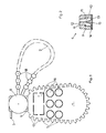
- la figure 1 est une vue en plan du sceau selon l'invention,
- la figure 2 est une vue en coupe selon la ligne II/II de la figure 1,
- la figure 3 est une vue en plan du sceau après sa fermeture.
- FIG. 1 is a plan view of the seal according to the invention,
- FIG. 2 is a sectional view along line II / II of FIG. 1,
- Figure 3 is a plan view of the seal after it is closed.
Tel que représenté en figure 1, le sceau d'identification et de contrôle selon l'invention comporte au moins une plaque de marquage 1 sur laquelle certaines inscriptions peuvent être réalisées, un lien 2 destiné à former une boucle pour l'attache du sceau sur l'objet ou l'animal et des moyens de fermeture inviolables de la boucle formée par le lien 2.As shown in FIG. 1, the identification and control seal according to the invention comprises at least one
Selon une forme préférentielle de réalisation mais non limitative, le sceau est doté d'une seule plaque de marquage 1.According to a preferred but nonlimiting embodiment, the seal is provided with a
Les moyens de fermeture comportent une partie mâle 3 et une partie femelle 4 destinées à coopérer en fermeture l'une avec l'autre pour maintenir fermée la boucle formée par le lien 2.
Le lien 2 du sceau selon l'invention est solidaire de façon détachable sur toute ou partie de sa longueur de la plaque de marquage 1, comporte à une de ses extrémités la partie mâle 3 ou femelle 4 des moyens de fermeture et est solidaire de façon fixe de la plaque de marquage 1 en un point éloigné sur sa longueur de l'extrémité portant la dite partie mâle ou femelle.The closing means comprise a male part 3 and a female part 4 intended to cooperate in closing with each other to keep the loop formed by the
The
Selon une forme préférentielle de réalisation, l'extrémité du lien 2 ne portant pas la partie mâle ou femelle des moyens de fermeture est solidaire de façon fixe de la plaque de marquage 1.
Selon cette forme de réalisation, l'autre partie des moyens de fermeture est solidaire de façon non détachable de la plaque de marquage.
Le lien 2 est solidaire de façon détachable de la plaque de marquage sur toute ou partie de sa longueur à partir de son extrémité portant la partie mâle 3 ou femelle 4 des moyens de fermeture.According to a preferred embodiment, the end of the
According to this embodiment, the other part of the closure means is integral in a non-detachable manner with the marking plate.
The
Selon une forme préférentielle de réalisation, le lien 2 est solidaire de façon détachable de la plaque 1 sur toute sa longueur et sur la périphérie de la dite plaque.
La solidarisation du lien 2 à la plaque de marquage 1 est effectuée par une pluralité de points de faiblesse 5 établis sur toute la longueur du lien 2 et sur la périphérie de la plaque 1 et se rompant sous l'effet d'une traction.According to a preferred embodiment, the
The
Une des extrémités du lien 2 porte la partie mâle 3 ou femelle 4 des moyens de fermeture qui est également solidarisée de façon détachable de la plaque de marquage 1.One of the ends of the
Ainsi, lorsque l'utilisateur veut former une boucle avec le lien 2, il est amené à séparer le dit lien de la plaque de marquage 1 en rompant les points de faiblesse 5 sur toute la longueur du dit lien.
Cette séparation du lien 2 de la plaque 1 constitue une présomption d'utilisation.
Cette séparation est réalisée à partir de l'extrémité du lien 2 portant la partie mâle ou femelle des moyens de fermeture et est poursuivie jusqu'à l'extrémité du dit lien qui est fixée de façon non détachable à la plaque de marquage 1.Thus, when the user wants to form a loop with the
This separation of the
This separation is carried out from the end of the
Ainsi, dès que le lien est séparé de la plaque 1, la boucle peut être formée puis fermée par coopération des parties mâle 3 et femelle 4.
Le lien 2 peut être solidarisé à la plaque 1 de façon détachable seulement sur une partie de sa longueur mais à partir de son extrémité portant la partie mâle 3 ou femelle 4 des moyens de fermeture.
Ainsi, la rupture des points de faiblesse 5 ménagés à partir de cette extrémité constitue également une présomption d'utilisation du sceau.
Préférentiellement, l'extrémité du lien 2 détachable porte la partie mâle 3 des moyens de fermeture, la partie femelle 4 étant solidarisée de façon non détachable à la plaque de marquage 1 mais il va de soi que l'inverse peut être réalisé.Thus, as soon as the link is separated from the
The
Thus, the rupture of the points of
Preferably, the end of the
Selon une forme préférentielle de réalisation, la partie mâle 3 des moyens de fermeture comporte une embase 6, sur laquelle sont ménagées en saillie deux pattes 7 parallèles espacées l'une de l'autre et dotées chacune sur leur face extérieure d'une barbelure 8.
Les faces des pattes 7 en regard sont divergentes en extrémités des dites pattes.
Ces dernières sont préférentiellement légèrement élastiques.
L'embase 6 est de préférence en forme de disque et le lien 2 vient s'y fixer radialement.According to a preferred embodiment, the male part 3 of the closure means comprises a base 6, on which are projecting two
The faces of the
The latter are preferably slightly elastic.
The base 6 is preferably in the form of a disc and the
La partie femelle 4 des moyens de fermeture telle que représentée aux figures 1 et 2 est constituée par un cube 9 fixé à la plaque de marquage 1 en sorte d'être en saillie par rapport à une face de la plaque.
Ce cube 9 est fixé de préférence en périphérie de la plaque 1.
Dans ce cube 9 est ménagé un logement 10 le traversant de part en part et débouchant préférentiellement sur les faces du dit cube parallèles à la plaque 1.
Le logement 10 est destiné à recevoir les pattes 7 de la partie mâle et à retenir celle-ci de façon inamovible.
A cet effet, deux faces parallèles du logement 10 sont pourvues chacune d'un épaulement 11 sur lesquels s'enclipsent les barbelures 8 des pattes 7 empêchant ainsi le retrait de la partie mâle 3.
Les épaulements 11 sont réalisés de façon oblique afin que les barbelures 8 viennent en appui par leur surface sur ceux-ci.
Préférentiellement, l'angle d'inclinaison des barbelures 8 et des épaulements 11 est le même.The female part 4 of the closing means as shown in FIGS. 1 and 2 is constituted by a cube 9 fixed to the
This cube 9 is preferably fixed at the periphery of the
In this cube 9 is provided a
The
For this purpose, two parallel faces of the
The shoulders 11 are produced obliquely so that the
Preferably, the angle of inclination of the
Le logement 10 est doté dans sa zone d'entrée de la partie mâle 3 d'une cloison 12 médiane ménagée parallèlement aux faces pourvues des épaulements 11.
Cette cloison 12 est destinée à se placer entre les pattes 7 de la partie mâle 3 pour centrer et guider cette dernière afin d'assurer une fermeture correcte et inamovible.
Le logement 10 du cube 9 est obstrué par un couvercle 13 fixé de façon inamovible dans un décrochement 14 ménagé sur la face du cube 9 parallèle à celle dotée de l'entrée du logement 10.
Le couvercle 13 est fixé dans le décrochement 14 par tout moyen connu et préférentiellement par soudure et en sorte de ne pas pouvoir être retiré.The
This partition 12 is intended to be placed between the
The
The
La fabrication de cette partie femelle 4 des moyens de fermeture est d'autant plus aisée par la présence de ce couvercle 13.
Le dit couvercle est doté sur sa face intérieure au logement 10 d'un élément de maintien en écartement des pattes 7 de la partie mâle.
Cet élément de maintien en écartement est constitué par une saillie 15 en forme de coin destinée à se placer dans le prolongement de la cloison 12 et à maintenir écartées les pattes 7 de la partie mâle en sorte que les barbelures 8 de celles-ci soient maintenues contre les épaulements 11 du logement 10.
Les pattes 7 viennent en contact avec la saillie conique 15 par les extrémités divergentes de leur face en regard.
Du fait de la coopération des barbelures 8 avec les épaulements 11, de la saillie 15 en forme de coin maintenant les pattes 7 écartées et de l'inaccessibilité à l'intérieur du logement 10, les moyens de fermeture du sceau selon l'invention sont inviolables.The manufacture of this female part 4 of the closing means is made all the easier by the presence of this
Said cover is provided on its inner face to the
This spacing holding element consists of a wedge-
The
Due to the cooperation of the
Avantageusement, autour de l'entrée du logement 10 est ménagé un lamage (non représenté) dans lequel vient se loger l'embase 6 de la partie mâle 3 en sorte que la dite embase ne soit pas en saillie sur le cube 9 et donc n'offre pas de prise à un outil pour une tentative d'effraction des moyens de fermeture du sceau.
Toujours selon cette forme de réalisation, l'embase 6 pourra présenter un contour qui épouse la forme d'un carré.
Le lien 2 se fixant de manière latérale à l'embase, il sera pratiqué dans le bourrelet délimitant le lamage, une encoche pour le passage du lien.Advantageously, around the entry of the
Still according to this embodiment, the base 6 may have a contour which follows the shape of a square.
The
La partie femelle 4 des dits moyens de fermeture est ménagée sur la périphérie de la plaque de marquage 1.The female part 4 of said closing means is formed on the periphery of the
Selon une forme préférentielle, le lien 2 est solidaire de façon non détachable par une de ses extrémités de la dite partie femelle tandis que l'autre extrémité du dit lien porte la partie mâle 3.According to a preferred form, the
La dite partie mâle est solidaire de façon détachable de la partie femelle 4 par le biais d'un point de faiblesse 5.Said male part is detachably secured to the female part 4 by means of a point of
La séparation du lien 2 se fait d'abord par rupture du point de faiblesse 5 entre la partie mâle 3 et la partie femelle 4 puis par rupture des autres points de faiblesse 5 entre le dit lien et la périphérie de la plaque 1, la partie mâle 3 pouvant ensuite coopérer en fermeture avec la partie femelle 4 verrouillant ainsi la boucle formée par le lien 2.The separation of the
La plaque de marquage 1 du sceau selon l'invention est équipée d'au moins une zone détachable 16 pouvant recevoir une inscription et d'une surface non détachable recevant également des inscriptions.
En outre, la dite plaque de marquage est dotée de moyens permettant de déterminer une date.
Ces moyens sont constitués par des zones détachables 16, par exemple, au nombre de 6 définissant un mois et par des plots 17 ménagés à la périphérie de la plaque et par exemple au nombre de 31 définissant les jours.
Les dits plots sont préférentiellement circulaires donnant ainsi à la plaque 1 un bord festonné.
De plus, ces plots circulaires permettent la fixation en un point du lien 2.
Ce dernier est fixé à la plaque 1 de façon détachable par des points de faiblesse 5 établie entre lui-même et les plots 17.
Ces plots 17 peuvent être retirés à l'aide d'un outil tranchant.
D'autre part, sur le lien 2 sont réalisés des bossages 18 sphériques sur chacun desquels est réalisé le point de faiblesse 5.
Ces bossages sphériques 18 sont de préférence au même nombre que les plots 17.
La forme sphérique des bossages 18 et circulaire des plots 17 permet plus aisément la réalisation des points de faiblesse 5.The
In addition, said marking plate is provided with means making it possible to determine a date.
These means are constituted by
Said pads are preferably circular, thus giving the plate 1 a scalloped edge.
In addition, these circular studs allow the attachment at a point of the
The latter is detachably fixed to the
These
On the other hand, on the
These
The spherical shape of the
De plus, les bossages sphériques 18 renforcent la solidité du lien 2 aux endroits où est exercée la traction de séparation du dit lien de la plaque 1.
La plaque 1 de marquage comporte également un orifice 19 permettant le passage d'un fil sur lequel peuvent être placés plusieurs sceaux selon l'invention pour leur transport.
Tel que représenté, la plaque de marquage 1 présente une forme ovoïde sans que celle-ci soit limitative.In addition, the
The marking
As shown, the marking
Selon une autre forme de réalisation du sceau selon l'invention, les extrémités du lien 2 portent chacune respectivement la partie mâle 3 et la partie femelle 4 des moyens de fermeture.
Le dit lien, selon cette autre forme de réalisation, est fixé de façon non détachable à la plaque 1 en partie médiane de sa longueur et est solidaire de la périphérie de la plaque de façon détachable entre son point de fixation non détachable et ses extrémités.According to another embodiment of the seal according to the invention, the ends of the
Said link, according to this other embodiment, is fixed in a non-detachable manner to the
Le sceau selon l'invention est préférentiellement en matière plastique et est réalisé par moulage par injection.
Le sceau permet d'éviter des utilisations multiples en créant une présomption d'utilisation dès sa première utilisation, est de fermeture aisée et inviolable et permet d'identifier et de dater l'objet ou l'animal sur lequel il est placé.The seal according to the invention is preferably made of plastic and is produced by injection molding.
The seal avoids multiple uses by creating a presumption of use from its first use, is easy and inviolable closure and allows to identify and date the object or animal on which it is placed.
La présente invention peut recevoir tous aménagements et toutes variantes dans le domaine des équivalents techniques sans pour autant sortir du cadre du présent brevet.The present invention can receive all arrangements and all variants in the field of technical equivalents without departing from the scope of this patent.
Claims (12)
Applications Claiming Priority (2)
| Application Number | Priority Date | Filing Date | Title |
|---|---|---|---|
| FR9005606 | 1990-04-27 | ||
| FR9005606A FR2661537B1 (en) | 1990-04-27 | 1990-04-27 | IDENTIFICATION AND CONTROL SEAL. |
Publications (1)
| Publication Number | Publication Date |
|---|---|
| EP0454571A1 true EP0454571A1 (en) | 1991-10-30 |
Family
ID=9396308
Family Applications (1)
| Application Number | Title | Priority Date | Filing Date |
|---|---|---|---|
| EP91401080A Withdrawn EP0454571A1 (en) | 1990-04-27 | 1991-04-23 | Identification and checking seal |
Country Status (2)
| Country | Link |
|---|---|
| EP (1) | EP0454571A1 (en) |
| FR (1) | FR2661537B1 (en) |
Cited By (1)
| Publication number | Priority date | Publication date | Assignee | Title |
|---|---|---|---|---|
| EP1076327A2 (en) * | 1999-08-07 | 2001-02-14 | Spirent plc | Security container |
Citations (5)
| Publication number | Priority date | Publication date | Assignee | Title |
|---|---|---|---|---|
| US1964897A (en) * | 1932-08-31 | 1934-07-03 | George J Wenk | Self-locking seal |
| US3367701A (en) * | 1966-01-14 | 1968-02-06 | American Casting And Mfg Corp | Self-locking plastic seal |
| EP0176120A1 (en) * | 1984-09-01 | 1986-04-02 | Halbe Jacobus Niemeijer | Marking seal |
| CH667773A5 (en) * | 1986-06-11 | 1988-11-15 | Biwi Sa | Marker tag for animals - comprises flexible strip with ends equipped with two halves of pressure fixing |
| US4793641A (en) * | 1987-06-09 | 1988-12-27 | Panduit Corp. | Tamper revealing seal |
-
1990
- 1990-04-27 FR FR9005606A patent/FR2661537B1/en not_active Expired - Lifetime
-
1991
- 1991-04-23 EP EP91401080A patent/EP0454571A1/en not_active Withdrawn
Patent Citations (5)
| Publication number | Priority date | Publication date | Assignee | Title |
|---|---|---|---|---|
| US1964897A (en) * | 1932-08-31 | 1934-07-03 | George J Wenk | Self-locking seal |
| US3367701A (en) * | 1966-01-14 | 1968-02-06 | American Casting And Mfg Corp | Self-locking plastic seal |
| EP0176120A1 (en) * | 1984-09-01 | 1986-04-02 | Halbe Jacobus Niemeijer | Marking seal |
| CH667773A5 (en) * | 1986-06-11 | 1988-11-15 | Biwi Sa | Marker tag for animals - comprises flexible strip with ends equipped with two halves of pressure fixing |
| US4793641A (en) * | 1987-06-09 | 1988-12-27 | Panduit Corp. | Tamper revealing seal |
Cited By (2)
| Publication number | Priority date | Publication date | Assignee | Title |
|---|---|---|---|---|
| EP1076327A2 (en) * | 1999-08-07 | 2001-02-14 | Spirent plc | Security container |
| EP1076327A3 (en) * | 1999-08-07 | 2001-03-21 | Spirent plc | Security container |
Also Published As
| Publication number | Publication date |
|---|---|
| FR2661537B1 (en) | 1992-08-14 |
| FR2661537A1 (en) | 1991-10-31 |
Similar Documents
| Publication | Publication Date | Title |
|---|---|---|
| FR2498912A1 (en) | FRAME FOR THE EXPOSURE OF OBJECTS | |
| FR2500319A1 (en) | TOY CONSISTS OF A CHAIN OF TRIANGULAR HOLLOW PRISMS | |
| EP0466656A1 (en) | Bracelet fastener | |
| FR2543717A1 (en) | MULTIPLE TAPE DISPENSER FOR MARKING ELECTRICAL COMPONENTS AND WIRES | |
| EP2134162B1 (en) | Tie for identification ring | |
| EP0454571A1 (en) | Identification and checking seal | |
| EP2437638A1 (en) | Packaging device forming a container | |
| CH667773A5 (en) | Marker tag for animals - comprises flexible strip with ends equipped with two halves of pressure fixing | |
| FR2688477A3 (en) | DEVICE FOR IRREVERSIBLE ATTACHMENT OF AN ACCESSORY TO THE NECK OF A BOTTLE. | |
| EP0284465B1 (en) | Ornamental button cover fitted through the button hole | |
| EP0238518A1 (en) | Frame-like card-holder | |
| EP2625115B1 (en) | Tamperproof wire cap | |
| FR2486035A1 (en) | CONTAINER-DISPENSER OF STACKED ARTICLES, ESPECIALLY SHELVES | |
| FR2536730A1 (en) | DEVICE FOR COLLECTING A WIRED MATERIAL | |
| EP0608580A1 (en) | Buckle | |
| EP0836822B1 (en) | Packaging and display device for jewelry and support or storage element to be used therein | |
| FR2934126A1 (en) | JEWELRY SET COMPRISING AT LEAST THREE SOLIDARIZED PIECES BETWEEN THEM. | |
| EP2229671B1 (en) | Tie for identification ring including a locking member | |
| FR2580595A1 (en) | Fastener for connecting the stopper to the spout of a tank | |
| FR2587172A1 (en) | Lead weighted tackle for fishing line | |
| EP0738480B1 (en) | Articulation device for connecting bracelet links | |
| FR2750020A1 (en) | EAR-LOOP DRILLING KIT FOR STUD GUNS | |
| CA2424939A1 (en) | Fixing and/or assembling device | |
| FR2779626A1 (en) | Device for jewelry presentation | |
| FR2753436A1 (en) | Tray for holding, displaying and opening bivalve shellfish e.g. oysters |
Legal Events
| Date | Code | Title | Description |
|---|---|---|---|
| PUAI | Public reference made under article 153(3) epc to a published international application that has entered the european phase |
Free format text: ORIGINAL CODE: 0009012 |
|
| AK | Designated contracting states |
Kind code of ref document: A1 Designated state(s): BE CH DE ES FR GB IT LI NL |
|
| 17P | Request for examination filed |
Effective date: 19920217 |
|
| 17Q | First examination report despatched |
Effective date: 19950308 |
|
| GRAG | Despatch of communication of intention to grant |
Free format text: ORIGINAL CODE: EPIDOS AGRA |
|
| GRAH | Despatch of communication of intention to grant a patent |
Free format text: ORIGINAL CODE: EPIDOS IGRA |
|
| STAA | Information on the status of an ep patent application or granted ep patent |
Free format text: STATUS: THE APPLICATION IS DEEMED TO BE WITHDRAWN |
|
| 18D | Application deemed to be withdrawn |
Effective date: 19960723 |