EP0454913A1 - Compensating for distortion in a communication channel - Google Patents
Compensating for distortion in a communication channel Download PDFInfo
- Publication number
- EP0454913A1 EP0454913A1 EP90304667A EP90304667A EP0454913A1 EP 0454913 A1 EP0454913 A1 EP 0454913A1 EP 90304667 A EP90304667 A EP 90304667A EP 90304667 A EP90304667 A EP 90304667A EP 0454913 A1 EP0454913 A1 EP 0454913A1
- Authority
- EP
- European Patent Office
- Prior art keywords
- signal
- correlation
- received signal
- signals
- generating
- Prior art date
- Legal status (The legal status is an assumption and is not a legal conclusion. Google has not performed a legal analysis and makes no representation as to the accuracy of the status listed.)
- Withdrawn
Links
- 238000004891 communication Methods 0.000 title description 3
- 238000000034 method Methods 0.000 claims abstract description 23
- 238000012546 transfer Methods 0.000 claims description 43
- 238000001228 spectrum Methods 0.000 claims description 37
- 230000001360 synchronised effect Effects 0.000 claims description 13
- 230000003111 delayed effect Effects 0.000 claims description 10
- 230000000644 propagated effect Effects 0.000 claims description 4
- 238000001914 filtration Methods 0.000 claims description 3
- 238000011084 recovery Methods 0.000 claims description 3
- 230000008878 coupling Effects 0.000 claims 2
- 238000010168 coupling process Methods 0.000 claims 2
- 238000005859 coupling reaction Methods 0.000 claims 2
- 238000004088 simulation Methods 0.000 claims 2
- 238000012545 processing Methods 0.000 abstract description 2
- 238000010586 diagram Methods 0.000 description 10
- 238000010276 construction Methods 0.000 description 3
- 230000005540 biological transmission Effects 0.000 description 2
- 230000015556 catabolic process Effects 0.000 description 2
- 238000006731 degradation reaction Methods 0.000 description 2
- 230000002452 interceptive effect Effects 0.000 description 2
- 230000003595 spectral effect Effects 0.000 description 2
- 229910000078 germane Inorganic materials 0.000 description 1
- 239000003365 glass fiber Substances 0.000 description 1
- 230000010354 integration Effects 0.000 description 1
- 238000005259 measurement Methods 0.000 description 1
- 230000010363 phase shift Effects 0.000 description 1
- 230000005855 radiation Effects 0.000 description 1
- 230000005236 sound signal Effects 0.000 description 1
- 230000002123 temporal effect Effects 0.000 description 1
Images


Classifications
-
- H—ELECTRICITY
- H04—ELECTRIC COMMUNICATION TECHNIQUE
- H04B—TRANSMISSION
- H04B1/00—Details of transmission systems, not covered by a single one of groups H04B3/00 - H04B13/00; Details of transmission systems not characterised by the medium used for transmission
- H04B1/69—Spread spectrum techniques
- H04B1/707—Spread spectrum techniques using direct sequence modulation
-
- H—ELECTRICITY
- H04—ELECTRIC COMMUNICATION TECHNIQUE
- H04L—TRANSMISSION OF DIGITAL INFORMATION, e.g. TELEGRAPHIC COMMUNICATION
- H04L27/00—Modulated-carrier systems
- H04L27/18—Phase-modulated carrier systems, i.e. using phase-shift keying
- H04L27/22—Demodulator circuits; Receiver circuits
- H04L27/227—Demodulator circuits; Receiver circuits using coherent demodulation
- H04L27/2275—Demodulator circuits; Receiver circuits using coherent demodulation wherein the carrier recovery circuit uses the received modulated signals
- H04L27/2278—Demodulator circuits; Receiver circuits using coherent demodulation wherein the carrier recovery circuit uses the received modulated signals using correlation techniques, e.g. for spread spectrum signals
Definitions
- This invention relates generally to a method and apparatus for the processing of a signal having cyclostationary properties and, more particularly, to a method and apparatus for estimating the transfer characteristics of a medium from the output of the medium and using the estimated transfer characteristics to improve the signal to noise ratio of a recovered cyclostationary signal.
- the spread spectrum may be produced by modulating an unspread baseband signal with the output of a spread spectrum sequence generator.
- the sequence generator generates a spreading signal having a level representative of either one or minus one at any given time.
- the spreading signal is most often referred to as a sequence of chips, each chip consisting of a period during which the spreading signal is of either a positive (one) or negative (minus one) polarity. It should be understood that the sequence is cyclically generated.
- the rate at which the chips are provided is known as the chip or clock rate. Additionally, the sequence has a defined pattern, known as the spread sequence. The defined pattern is the encryption referred to hereinabove.
- the modulation of the unspread baseband signal provides a spread signal having an amplitude which is the product of the level of the spreading signal and the amplitude of the baseband signal.
- the spread signal has an increased spectral width that substantially equals the spectral width of the spreading signal.
- the spread signal Since all of the chips have substantially identical pulse shapes, the spread signal has statistical characteristics that vary cyclically. Hence, the spread signal is referred to in the art as a cyclostationary signal.
- a signal substantially the same as the unspread baseband signal, is recovered by modulating the spread signal with a local spreading signal provided by a local spread sequence signal generator at the receiving station.
- the output of the local sequence generator must be synchronized to the received signal to accomplish the recovery.
- the baseband signal may be an audio signal, the output of a Phase Shift Keyed (PSK) generator, a light signal, or the output of any of a plethora of generators used to provide signals for propagation through a medium.
- the medium may be the atmosphere, the earth, a glass fiber or any other medium.
- Transmission through the medium may cause distortion of the spread signal.
- the distortion manifests itself as a degradation of the signal to noise ratio of the recovered baseband signal. It is well known that the degradation is reduced by appropriately modifying the local spreading signal.
- An appropriately modified local spreading signal is obtained by altering the local spreading signal in accordance with the transfer characteristics of the medium.
- the transfer characteristics may be unknown and may be subject to temporal changes. It is desirable to determine the transfer characteristics from the output of the medium, and use it to improve the signal to noise ratio of the recovered baseband signal.
- This invention covers those spread and unspread signals which are included or encompassed by the term cyclostationary signals.
- An object of the present invention is an improved apparatus for providing a recovered baseband signal.
- Another object of the present invention is an improved method for providing a recovered baseband signal.
- Yet another object of the present invention is to provide an improved method and apparatus to estimate the transfer characteristics of a propagation medium.
- a medium estimator generates a plurality of pairs of signals in response to a cyclostationary signal received through a propagation medium.
- One signal of each estimator pair is representative of a portion of an in-phase component of a correlation signal.
- the other signal of each estimator pair is representative of a portion of a quadrature component of the correlation signal.
- a computer utilizes a representation of an assumed set of values of coefficients in a model of the transfer characteristics of the medium.
- the computer utilizes the implementation to generate pairs of correlation model signals that respectively correspond to the pairs of estimator signals.
- the representation of the coefficients is varied to reduce the difference between the correlation model signals and the corresponding pairs of estimator signals.
- the invention provides an improved apparatus and method for estimating transfer characteristics of a medium from the output of the medium.
- the estimation is independent of spread sequence and carrier frequency. Moreover, the estimation does not utilize epoch synchronization between a local spread sequence generator and the spread signal.
- a data pulse source 10A provides data pulses of either positive or negative polarity.
- the polarity is in accordance with an encoding of information represented by the pulses.
- the pulses are transmitted through a medium 14A that has a transfer function H(w).
- the output of medium 14A is provided to one of two inputs of an adder 16A.
- the other input of adder 16A is connected to a noise source 18A.
- Adder 16A provides a signal substantially equal to the sum of signals respectively applied to its inputs. Hence, at the output of adder 16A there is a signal that is corrupted by noise.
- a matched filter 20A includes an equalizer network 22A that is connected to the output of adder 16A, whereby the signal at the output of adder 16A is applied to the input of matched filter 20A.
- Equalizer 22A has a transfer function represented by the term H*(w) that is the complex conjugate of the transfer function of medium 14A.
- circuit 24A provides a signal representative of the average amplitude of a signal applied at its input. At the end of the pulse period, circuit 24A is made to provide an initial a value signal representative of zero.
- matched filter 20A provides an output having an enhanced signal to noise ratio. It should also be understood that when noise provided by source 18A is of sufficiently low amplitude, the transfer function, H(w), may be accurately determined by measurements, thereby readily enabling construction of equalizer 22A. Conversely, when source 18A provides a high noise level, construction of equalizer 22A is difficult.
- the embodiments herein relate to construction of a matched filter for a cyclostationary signal.
- a multiplier circuit 12 has two inputs, one of which is connected to a baseband generator 14. As shown graphically in Fig. 2(a), baseband generator 14 provides a signal having a baseband power density spectrum.
- multiplier 12 is connected to the output of a reference spread spectrum sequence generator 16a (Fig. 1) that generates a spreading signal.
- Multiplier 12 is a well-known type of circuit that provides a signal having an amplitude proportional to the product of two signals respectively applied to its inputs. Therefore, in response to the baseband signal and the spreading signal, multiplier 12 provides a signal having a spread baseband power density spectrum graphically represented in Fig. 2(b).
- the output of multiplier 12 (Fig. 1) is coupled to a propagation medium 18.
- the output of medium 18 is coupled to one of two inputs of an adder 19.
- the other input of adder 19 is connected to a source of noise 20.
- Adder 19 is similar to adder 16A described in connection with Fig. 1A. Accordingly, at the output of adder 19, there is a propagated spread baseband signal that is corrupted by noise.
- the output of adder 19 is referred to hereinafter as a received signal. It should be understood that noise produced by source 20 may be atmospheric noise, receiver noise, or any other noise that is introduced in a communication channel.
- the output of adder 19 is connected to a medium estimator 22.
- Medium estimator 22 generates correlation signals representative of components of the autocorrelation of the received signal.
- Medium estimator 22 is connected to one of two inputs of a simulator 24, whereby the correlation signals are provided to simulator 24.
- simulator 24 utilizes only the correlation signals to generate a representation of coefficients in an equation of a model of the transfer characteristics of medium 18.
- the model is an estimate of the transfer characteristics of propagation medium 18.
- the other input of simulator 24 is coupled to a local spread sequence generator 16b through a time delay network 26.
- sequence generators 16a, 16b are synchronized to each other by apparatus that is not shown. The synchronization of sequence generators is well known in the art.
- Time delay network 26 provides a delay for synchronizing the output of generator 16b to the received signal.
- simulator 24 modifies the output of generator 16b of Fig. 1. Because the output of generator 16b of Fig. 1 is modified, the transfer function, rather than its complex conjugate is utilized in this embodiment.
- the output of adder 19 is connected to one of two inputs of a multiplier unit 28.
- the other input of multiplier 28 is connected to the output of simulator 24.
- Multiplier 28 is similar to multiplier 12 described hereinbefore.
- simulator 24 has transfer characteristics similar to those of medium 18. Therefore, the output of simulator 24 is a modified local spreading signal that causes multiplier 28 to provide on an output signal line 30 a recovered baseband signal with an enhanced signal to noise ratio.
- the present invention is predicated upon a Fourier transform relationship between a correlation of the output of medium 18 and the transfer function of medium 18.
- the transform relationship is given as: where C n ( ⁇ k ) is the autocorrelation of the output of medium 18, with a correlation delay, ⁇ k; n is an index of harmonics of the chip rate; w n is the radian frequency of the n th harmonic of the chip rate; w is a radian frequency; T is the spread period; ⁇ s is a timing synchronization offset; P(w) is the Fourier transform of a pulse provided by generator 16a; and P*(w) is the complex conjugate of P(w); H(w) is the transfer function of medium 18; and H*(w) is the complex conjugate of H(w).
- the transform relationship is a variation of a generalized equation in "Generalized Cross-Spectrum Symbol Synchronization" by R. McCallister, which is a doctoral thesis written in 1981 at Arizona State University. It should be understood that the transform relationship is that of a Fourier transform pair.
- medium estimator 22 includes a plurality of correlation units 36 respectively connected to a plurality of down converters 38 through a plurality of signal lines 40.
- each of converters 38 provide signals representative of two of the terms, C n ( ⁇ k ) of the transform relationship, where:
- a typical correlation unit 42 is comprised of a time delay network 46 that has its input connected to the output of adder 19. Additionally, a multiplier unit 48 has one of its two inputs connected to the output of adder 19. The other input of multiplier 48 is connected to the output of delay network 46.
- Delay network 46 is a well-known type of circuit that provides an output substantially the same as an input signal applied thereto, but delayed by a known time. Accordingly, the output of delay network 46 is a delayed received signal. Delay network 46 provides the correlation delay ⁇ 1 for unit 42.
- Multiplier 48 is similar to multiplier 12 described hereinbefore.
- the output of multiplier 48 has a component proportional to the autocorrelation of the received signal, with the correlation delay ⁇ 1 and a noise component.
- the noise component of the output of the multiplier 48 is spectrally diffuse, with power within a given noise bandwidth directly proportional to the noise bandwidth.
- the ⁇ 1 correlation signal component is spectrally discrete, with power at harmonics of the chip rate. In other words, the power at any given harmonic is completely contained within any bandwidth about the given harmonic.
- the output of multiplier 48 is connected to a low pass filter 52 at its input.
- Filter 52 provides the ⁇ 1 correlation signal, while eliminating much of the noise referred to hereinbefore.
- the ⁇ 1 correlation signal includes a group of signals 56, each at a frequency that is a harmonic of the chip rate.
- Signals 56a, 56b, for example, are at the fundamental and second harmonic, respectively, of the chip rate.
- Experimental results conclusively show that few of the harmonics need be utilized in estimating transfer characteristics of medium 18. In this embodiment, only the first and second harmonics are utilized.
- Converters 38 are additionally connected to a chip rate reference source 58 that generates a sinusoidal signal having a frequency equal to the chip rate.
- the timing synchronization offset ⁇ s referred to in connection with the transform relationship, is a timing difference between the fundamental frequency component of the spreading signal transmitted through medium 18 and the signal generated by source 58.
- Source 58 is connected to the input of a frequency doubler 69.
- the output of doubler 69 is connected to converters 38.
- Doubler 69 generates a sinusoidal signal having a frequency of twice the chip rate. Frequency doublers are well-known in the art.
- converters 38 include a typical converter 57 which is similar to all others of converters 38.
- Converter 57 includes a hybrid 63 that has its input connected to source 58.
- Hybrid 63 is a well-known type of network that has an output that provides an in-phase (zero degree) output signal, substantially the same as a signal applied at its input.
- Hybrid 63 additionally has an output that provides a quadrature output signal that is phase shifted by 90 degrees.
- the in-phase output of hybrid 63 is connected to a multiplier unit 62 at one of two inputs thereof.
- the other input of multiplier 62 is connected to the output of unit 42, whereby the ⁇ 1 correlation signal is applied to multiplier 62.
- Multiplier 62 is similar to multiplier 12 described hereinbefore.
- multiplier 62 down converts an in-phase component of the ⁇ 1 correlation signal to provide a DC voltage, referred to as a first harmonic ⁇ 1 in-phase estimator signal, and noise.
- the first harmonic ⁇ 1 in-phase estimator signal is represented by the term Re ⁇ C1( ⁇ 1) ⁇ .
- the output of multiplier 62 is connected to a low pass filter 64 at its input. Filter 64 rejects the noise produced by multiplier 62.
- the output of unit 42 is additionally connected to a multiplier unit 66 at one of two inputs thereof whereby the correlation signal is applied to multiplier 66.
- Multiplier 66 is similar to multiplier 12 described hereinbefore.
- the other input of multiplier 66 is connected to the quadrature output of hybrid 63.
- multiplier 66 down converts a quadrature component of the correlation signal to provide a DC voltage, referred to as a first harmonic ⁇ 1 quadrature estimator signal, and noise.
- the first harmonic ⁇ 1 quadrature estimator signal is represented by the term Im ⁇ C1( ⁇ 1) ⁇ .
- multiplier 66 The output of multiplier 66 is connected to a low pass filter 68 at its input.
- Filter 68 similar to filter 64, rejects the noise produced by multiplier 66.
- Hybrid 65 is similar to hybrid 63 described hereinbefore.
- the in-phase output of hybrid 65 is connected to one of two inputs of a multiplier unit 70.
- the other input of multiplier 70 is connected to the output of unit 42 whereby the correlation signal is applied to multiplier 70.
- Multiplier 70 is similar to multiplier 12 described hereinbefore.
- multiplier 70 The output of multiplier 70 is connected to a low pass filter 72 at its input.
- filter 72 provides a substantially noise-free, second harmonic ⁇ 1 in-phase estimator signal represented by the term Re ⁇ C2( ⁇ 1) ⁇ .
- the quadrature output of hybrid 65 is connected to a multiplier unit 74 at one of two inputs thereof.
- the other input of multiplier 74 is connected to the output of unit 42 whereby the ⁇ 1 correlation signal is applied to multiplier 74.
- Multiplier 74 is similar to multiplier 12 described hereinbefore.
- multiplier 74 The output of multiplier 74 is connected to a low pass filter 76 at its input.
- filter 76 provides a substantially noise-free, second harmonic ⁇ 1 quadrature estimator signal represented by the term Im ⁇ C2( ⁇ 1) ⁇ .
- converters 38 FIG. 3 to provide a representation of the terms C n ( ⁇ k ).
- a representation of the outputs of converters 38 are points with equal abscissa intervals therebetween. Abscissa values of the points are representative of delay times respectively associated with the time delay networks of correlation units 36. Because of the transform relationship, an interval 78a between points having adjacent abscissa values map into an interval 80a, with a maximum frequency 82a. It should be understood that the sizes of intervals 78a, 80a are inversely related. Accordingly, interval 78a is a choice based upon bandwidth considerations.
- interval 78a between points having adjacent abscissa values map into an interval 80b.
- intervals 78a, 80a, intervals 78b, 80b are inversely related. Accordingly, the size of interval 78b is a choice based upon a desired resolution of medium transfer characteristics.
- Converters 38 are connected through a plurality of signal lines 84 to simulator 24 (Fig. 1). Within simulator 24, a functional relationship is modeled as an approximation of the transfer characteristics of medium 18. As explained hereinafter, coefficients in the functional relationship are iteratively adjusted to reduce the difference between the representation of the terms C n ( ⁇ k ) and a corresponding representation of terms obtained by a computation utilizing the transform and the functional relationships.
- the functional relationship is given as: where H m (w) is the m th iterative transfer function; ⁇ im is the m th iterative value of the i th numerator coefficient; ⁇ im is the m th iterative value of the i th denominator coefficient; and N is the number of coefficients, ⁇ i or ⁇ i , utilized in forming the functional relationship.
- Simulator 24 includes a digital computer (not shown) of any suitable type to perform a Fourier transform operation on the model in accordance with the transform relationship given hereinbefore. More particularly, the transform relationship, as it relates to the model, may be written as: where C (1)n ( ⁇ k ) is the discrete portion of the complex correlation of the output of the model, with a correlation delay ⁇ k . The terms C (1)n ( ⁇ k ) are represented by correlation model signals.
- the computer utilizes the output of converters 38 and the model signals to generate a signal representation of a sum square error which is given as: where E is the sum square error.
- the computer iteratively adjusts the numerator and denominator coefficients to reduce the sum square error, thereby providing an estimate, with increased accuracy, of the transfer characteristics of medium 18.
- the coefficients are utilized by simulator 22 to simulate the transfer characteristics.
- the computer may perform a Fourier transform operation on the estimator signals to produce a set of frequency domain signals that are compared with a signal representation of the model; the difference therebetween is reduced by the iterative adjustment of the coefficients.
- a first baseband generator 84a and a second baseband generator 84b independently generate a first baseband signal and a second baseband signal respectively.
- the first and second baseband signals both share the baseband power density spectrum (Fig. 2(a)).
- multiplier 86a The output of generator 84a is connected to a multiplier unit 86a at one of two inputs thereof.
- the other input of multiplier 86a is connected to the output of generator 16a.
- Multiplier 86a is similar to multiplier 12 described in connection with the first embodiment. Accordingly, multiplier 86a provides a first spread baseband signal having the spread baseband power density spectrum (Fig. 2(b)).
- generators 16a, 116a generate first and second spread sequences that differ from each other. However, the first and second spread sequences are generated by generators 16a, 116 at the same chip rate.
- the first spread baseband signal is represented by the term d I (t) S I (t).
- generator 84b is connected to a multiplier unit 86b at one of two inputs thereof.
- the other input of multiplier 86b is connected to generator 116a.
- multiplier 86b is similar to multiplier 12 described hereinbefore.
- multiplier 86b provides a second spread baseband signal having the spread baseband power density spectrum.
- An RF carrier generator 88 has its output connected to the input of a hybrid 90.
- Generator 88 provides an RF carrier signal used to RF modulate the spread signals provided by multipliers 86a, 86b in a manner explained hereinafter.
- Hybrid 90 is similar to hybrid 63 described in connection with the first embodiment.
- hybrid 90 In response to an RF carrier generated by generator 88, hybrid 90 provides an in-phase carrier signal, represented by the term cos(w c t), and a quadrature carrier signal represented by the term sin(w c t), at the in-phase and quadrature outputs thereof, respectively.
- the in-phase output of hybrid 90 is connected to a multiplier unit 92 at one of two inputs thereof.
- the other input of multiplier 92 is connected to the output of multiplier 86a.
- Multiplier 92 is similar to multiplier 12 described hereinbefore. As shown in Fig. 2(c), multiplier 92 provides an RF modulated signal having a spectrum with a central portion displaced from the origin by the carrier frequency.
- the output of multiplier 92 is a first modulated spread spectrum signal represented by the term d I (t)S I (t)cos(w c t).
- the quadrature output of hybrid 90 is connected to a multiplier unit 94 at one of two inputs thereof.
- the other input of multiplier 94 is connected to the output of multiplier 86B.
- multiplier 94 is similar to multiplier 12.
- multiplier 94 provides an RF modulated signal having the power density spectrum with the central portion displaced from the origin.
- the output of multiplier 94 is a second modulated spread spectrum signal represented by the term d Q (t)S Q (t)sin(w c t).
- the outputs of multipliers 92, 94 are connected to an adder 96 at respective inputs thereof.
- the output of adder 96 is coupled to medium 18.
- Adder 96 is similar to adder 16a.
- medium 18 is represented as a filter with sections 18A, 18B responsive only to input signals represented by terms proportional to cos(w c t).
- Medium 18 additionally includes sections 18C and 18D which respond only to input signals represented by terms proportional to sin(w c t).
- the output of medium 18 is the sum of the outputs of sections 18A, 18B, 18C, 18D. Additionally, the carat notation ( ⁇ ) is indicative of a distortion that may be caused by medium 18.
- the propagated signal at the output of adder 96 is utilized to provide the input to medium 18.
- the output of medium 18 is given as:
- the output of adder 19 is connected to the input of a synchronized carrier frequency generator 98, whereby the received signal is applied to generator 98.
- the output of generator 98 is a carrier signal synchronized to the output of generator 88. Synchronized carrier generators are well-known to those skilled in the art.
- Hybrid 100 is similar to hybrid 63. In a manner similar to hybrid 90, hybrid 100 provides an in-phase synchronized carrier signal represented by the term cos(w c t) and a synchronized quadrature carrier signal represented by the term sin(w c t) at in-phase and quadrature outputs thereof, respectively.
- the in-phase output of hybrid 100 is connected to a multiplier unit 102 at one of two inputs thereof.
- the other input of multiplier 102 is connected to the output of adder 19 whereby the received signal is applied to multiplier 102.
- Multiplier 102 is similar to multiplier 12.
- multiplier 102 Because multiplier 102 is connected to the in-phase output of hybrid 100, multiplier 102 synchronously demodulates a portion of the received signal that is in phase with the synchronized carrier signal. More particularly, when the output of generator 20 is neglected, the output of multiplier 102 is in accordance with a relationship which is given as: where M 102OUT is the output of multiplier 102.
- the output of multiplier 102 is connected to the input of a low pass filter 102A.
- Filter 102A rejects frequency components greater than the carrier frequency w c .
- the output of filter 102A is in accordance with a relationship which is given as: where M 102F is the output of filter 102A.
- Filter 102A provides a first type of in-phase spread spectrum signal.
- the output of adder 19 is connected to a multiplier unit 104 at one of two inputs thereof.
- the other input of multiplier 104 is connected to the quadrature output of hybrid 100.
- Multiplier 104 is similar to multiplier 12. Therefore, multiplier 104 synchronously demodulates a portion of the received signal that is in quadrance with the synchronized carrier signal. More particularly, when the output of generator 20 is neglected, the output of multiplier 104 is in accordance with a relationship which is given as: where M 104OUT is the output of multiplier 104.
- the output of multiplier 104 is connected to the input of a low pass filter 104A.
- Filter 104A rejects frequency components greater than the carrier frequency w c .
- the output of filter 104A is in accordance with a relationship which is given as: where M 104F is the output of filter 104A.
- Filter 104A provides a first type of quadrature spread spectrum signal.
- the first type of in-phase and quadrature spread spectrum signals are utilized to provide a pair of recovered baseband signals that are respectively similar to the first and second baseband signals.
- An estimated carrier frequency generator 106 generates an estimated carrier signal having a frequency approximately equal to the frequency of the signals provided by generators 88, 98.
- the output of generator 106 is connected to the input of a hybrid 108, whereby the estimated carrier is applied to hybrid 108.
- Hybrid 108 is similar to hybrid 63.
- the in-phase output of hybrid 108 is connected to a multiplier unit 110 at one of two inputs thereof.
- the other input of multiplier 110 is connected to the output of adder 19 whereby the received signal is applied to multiplier 110.
- Multiplier 110 is similar to multiplier 12.
- multiplier 110 Because multiplier 110 is connected to the in-phase output of hybrid 108, multiplier 110 down converts a portion of the received signal that is in-phase with the estimated carrier signal. Hence, multiplier 110 provides a second type of in-phase spread spectrum signal.
- multiplier 112 In a similar manner, the output of adder 19 is connected to a multiplier unit 112 at one of two inputs thereof. The other input of multiplier 112 is connected to the quadrature output of hybrid 108. Multiplier 112 is similar to multiplier 12. Therefore, multiplier 112 down converts a portion of the received signal that is in quadrature with the estimated carrier signal. Hence, multiplier 112 provides a second type of quadrature spread spectrum signal.
- first and second types of spread spectrum signals differ because unlike generators 88, 98, generators 88, 106 are not synchronized to each other. In an alternative embodiment, only the first type of spread spectrum signals are utilized.
- the outputs of multiplier 110, 112 are connected to a medium estimator 114.
- Medium estimator 114 utilizes the second type of spread spectrum signals to generate a representation of the coefficients in the equation of the model of the transfer characteristics of medium 18.
- Medium estimator 114 is connected to a simulator 116 through a plurality of signal lines 118, whereby the signal representation of the coefficients is provided to simulator 116.
- Simulator 116 is additionally connected to the output of an adder 103 through a time delay network 26a.
- the inputs of adder 103 are connected to the outputs of local spread sequence generators 166a, 166b, respectively.
- Generators 166a, 166b are similar to generators 16a, 116a, respectively. Moreover, generator 166a is synchronized to generator 16a. Similarly, generator 166b is synchronized to generator 116a. Adder 103 and delay network 26a are respectively similar to adder 12 and delay network 26.
- medium estimator 114 is comprised of a plurality of correlation units 115, each of which is connected to the outputs of multipliers 110, 112. Additionally, the outputs of correlation units 115 are respectively connected to a plurality of down converters 120 through a plurality of pairs of signal lines 122. In a manner analogous to converters 38, each of converters 120 provides signal representations of four of the terms of a modified transform relationship which is given as: where W o is a difference in frequency between generators 88, 106.
- each of correlation units 115 includes the delay network with the unique value of delay.
- correlation units 115 include a typical correlation unit 121 comprised of delay network 46 with its input connected to the output of multiplier 110. Additionally, the output of multiplier 110 is connected to a multiplier unit 124 at one of two inputs thereof. The other input of multiplier 124 is connected to the output of delay network 46. Therefore, the second type of in-phase spread spectrum signal is applied to delay network 46 and multiplier 124. Multiplier 124 is similar to multiplier 12.
- the output of delay network 46 is additionally connected to a multiplier unit 126 at one of two inputs thereof.
- the other input of multiplier 126 is connected to the output of multiplier 112. Therefore, the second type of quadrature spread spectrum signal is applied to multiplier 126.
- Multiplier 126 is similar to multiplier 12.
- the output of multiplier 124 has a component proportional to an in-phase part of the complex correlation of the received signal with a delay ⁇ 1 and a noise component.
- the output of multiplier 126 has a component proportional to a quadrature part of the complex correlation of the received signal with a delay ⁇ 1 and a noise component. It should be understood that the ⁇ 1 in-phase and quadrature correlation signals are spectrally discrete, similar to the correlation signals described in connection with the first embodiment.
- multipliers 124, 126 are respectively connected to low pass filters 128, 130 at inputs thereof. Filters 128, 130 reject noise produced by multipliers 124, 126, respectively.
- Converters 120 are additionally connected to source 58 and doubler 69 described hereinbefore (Fig. 9). Converters 120 include a typical converter 131 which is similar to all others of converters 120.
- source 58 is connected within converter 131 to hybrid 132 at its input.
- the in-phase output of hybrid 132 is connected to multiplier units 134, 135 at inputs thereof through signal lines 134A, 135B, respectively.
- the other inputs of multipliers 134, 135 are connected to unit 121 (Fig. 9) through signal lines 122a, 122b, respectively.
- Multipliers 134, 135 are similar to multiplier 12. Multipliers 134, 135 down convert the ⁇ 1 in-phase and quadrature correlation signals in a manner corresponding to that described in connection with the first embodiment.
- the quadrature output of hybrid 132 is connected to multiplier units 136, 137 at inputs thereof through signal lines 136a, 137a, respectively.
- the other inputs of multipliers 136, 137 are connected to unit 121 through signal lines 122a, 122b, respectively.
- Multipliers 136, 137 are similar to multiplier 12.
- Multipliers 136, 137 down convert the ⁇ 1 in-phase and quadrature correlation signals in a manner corresponding to that described in connection with the first embodiment.
- Adder 140 is similar to adder 16A. Adder 140 provides a ⁇ 1 first harmonic estimator signal represented by the term Re ⁇ C ⁇ 1( ⁇ 1) ⁇ and noise.
- the outputs of multipliers 134, 137 are additionally connected to a subtractor 142 at respective inputs thereof.
- Subtractor 142 is similar to subtractor 89A.
- Subtractor 142 provides a ⁇ 1 first harmonic in-phase estimator signal, represented by the term Re ⁇ C+1( ⁇ 1) ⁇ and noise.
- adder 144 The outputs of multipliers 135, 136 are connected to respective inputs of an adder 144.
- Adder 144 is similar to adder 16A. Because of the phase of signals applied to multipliers 135, 136, adder 144 provides a ⁇ 1 first harmonic quadrature estimator signal, represented by the term Im ⁇ C+1( ⁇ 1) ⁇ and noise.
- the outputs of multipliers 135, 136 are additionally connected to a subtractor 146 at respective inputs thereof.
- Subtractor 146 is similar to subtractor 89A.
- Subtractor 146 provides a ⁇ 1 first harmonic quadrature estimator signal, which is represented by the term Im ⁇ C ⁇ 1( ⁇ 1) ⁇ and noise.
- the output of doubler 69 is connected to a hybrid 148 at its input.
- the in-phase output of hybrid 148 is connected to multiplier units 150, 151 at inputs thereof through signal lines 150a, 151a, respectively.
- the other inputs of multipliers 150, 151 are connected to unit 121 through signal lines 122a, 122b, respectively.
- Multipliers 150, 151 are similar to multiplier 12. Multipliers 150, 151 down convert the ⁇ 1 in-phase and quadrature correlation signals in a manner corresponding to that described in connection with the first embodiment.
- the quadrature output of hybrid 148 is connected to multiplier units 152, 153 at inputs thereof through signal lines 152a, 153a, respectively.
- the other inputs of multipliers 152, 153 are connected to unit 121 through signal lines 122a, 122b, respectively.
- Multipliers 152, 153 are similar to multiplier 12.
- Multipliers 152, 153 down convert the ⁇ 1 in-phase and quadrature correlation signals in a manner corresponding to that described in connection with the first embodiment.
- adder 154 is similar to adder 16a. Because of the phase of signals applied to multipliers 150, 153, adder 154 provides a ⁇ 1 second harmonic in-phase estimator signal represented by the term Re ⁇ C ⁇ 2( ⁇ 1) ⁇ and noise.
- the outputs of multipliers 150, 153 are additionally connected to a subtractor 156 at respective inputs thereof.
- Subtractor 156 is similar to subtractor 142.
- Subtractor 156 provides a ⁇ 1 second harmonic in-phase estimator signal represented by the term Re ⁇ C+2( ⁇ 1) ⁇ and noise.
- adder 158 is similar to adder 16A. Because of the phase of signals applied to multipliers 151, 152, adder 158 provides a ⁇ 1 second harmonic quadrature estimator signal represented by the term I m ⁇ C+2( ⁇ 1) ⁇ and noise.
- the outputs of multipliers 151, 152 are additionally connected to a subtractor 160 to respective inputs thereof.
- Subtractor 160 is similar to subtractor 142.
- Subtractor 160 provides a ⁇ 1 second harmonic quadrature estimator signal represented by the term I m ⁇ C ⁇ 2( ⁇ 1) ⁇ and noise.
- the outputs of adder 140, subtractor 142, adder 144 and subtractor 146 are respectively connected to low pass filters 162-165 at their inputs. Filters 162-165 reject the noise provided by multipliers 134-137. The outputs of filters 162-165 are connected to simulator 116 through some of lines 118 as described hereinafter.
- the outputs of adder 154, subtractor 156, adder 158 and subtractor 160 are respectively connected to low pass filters 166-169 at their inputs. Filters 166-169 reject the noise provided by multipliers 150-153. The outputs of filters 166-169 are connected to simulator 116 through some of lines 118 as described hereinbefore.
- simulator 116 (Fig. 8) simulates the transfer characteristics of medium 18. Simulator 116 provides modified first and second spreading signals.
- the first modified spreading signal is applied to multipliers 170, 172 at one of two inputs of each, via a signal line 174.
- the second modified spreading signal is applied to multiplier units 176, 178 at one of two inputs of each, via a signal line 180.
- Multipliers 170, 172, 176, 178 are all similar to multiplier 12.
- multipliers 170, 176 are connected to the output of multiplier 102.
- the other inputs of multipliers 172, 178 are connected to the output of multiplier 104.
- the output of multiplier 170 is in accordance with a relationship which is given as: where M170(t) is representative of the amplitude of the output of multiplier 170.
- the output of multiplier 172 is in accordance with a relationship which is given as: where M172(t) is representative of the amplitude of the output of multiplier 172.
- the output of multiplier 176 is in accordance with a relationship which is given as: where M176(t) is representative of the amplitude of the output of multiplier 176.
- multiplier 178 is in accordance with a relationship which is given as: where M178(t) is representative of the amplitude of the output of multiplier 178.
- the outputs of multipliers 172, 176 are connected to respective inputs of a subtractor 182.
- Subtractor 182 is similar to subtractor 89A.
- the output of subtractor 182 is in accordance with an output relationship which is given as: where D 2OUT (t) is representative of the amplitude of the output of subtractor 182.
- circuit 186 in response to the output of subtractor 182, circuit 186 provides a recovered baseband signal substantially equal to the second baseband signal.
- circuit 188 provides a recovered baseband signal substantially equal to the first baseband signal.
Abstract
This disclosure relates to a technique for estimating the characteristics of a propagation channel by processing a cyclostationary signal which has passed through it. The technique extends to the use of this estimate to reduce the impact of the channel distortion on the recovered signal. Unique features of this technique include its ability to function even when strong interference is present with the cyclostationary signal of interest.
Description
- This invention relates generally to a method and apparatus for the processing of a signal having cyclostationary properties and, more particularly, to a method and apparatus for estimating the transfer characteristics of a medium from the output of the medium and using the estimated transfer characteristics to improve the signal to noise ratio of a recovered cyclostationary signal.
- Since World War II, there has been an increasing interest in propagation of a signal with a direct sequence spread baseband spectrum. The increasing interest persists because at any given level of radiation, spreading causes a reduced power density over the spread spectrum. Additionally, encryption is almost inherent in the spreading. Because of the reduced power density and the encryption, a multiplicity of sources may simultaneously radiate at frequencies within the spread spectrum without interfering at a receiving station. Since the multiplicity of sources may simultaneously radiate without interfering, the spread spectrum may be used to achieve what is referred to in the art as code division multiple access.
- More particularly, the spread spectrum may be produced by modulating an unspread baseband signal with the output of a spread spectrum sequence generator. Typically, the sequence generator generates a spreading signal having a level representative of either one or minus one at any given time. The spreading signal is most often referred to as a sequence of chips, each chip consisting of a period during which the spreading signal is of either a positive (one) or negative (minus one) polarity. It should be understood that the sequence is cyclically generated.
- The rate at which the chips are provided is known as the chip or clock rate. Additionally, the sequence has a defined pattern, known as the spread sequence. The defined pattern is the encryption referred to hereinabove.
- The modulation of the unspread baseband signal provides a spread signal having an amplitude which is the product of the level of the spreading signal and the amplitude of the baseband signal. The spread signal has an increased spectral width that substantially equals the spectral width of the spreading signal.
- Since all of the chips have substantially identical pulse shapes, the spread signal has statistical characteristics that vary cyclically. Hence, the spread signal is referred to in the art as a cyclostationary signal.
- It should be understood that a signal, substantially the same as the unspread baseband signal, is recovered by modulating the spread signal with a local spreading signal provided by a local spread sequence signal generator at the receiving station. The output of the local sequence generator must be synchronized to the received signal to accomplish the recovery.
- The baseband signal may be an audio signal, the output of a Phase Shift Keyed (PSK) generator, a light signal, or the output of any of a plethora of generators used to provide signals for propagation through a medium. Moreover, the medium may be the atmosphere, the earth, a glass fiber or any other medium.
- Transmission through the medium may cause distortion of the spread signal. The distortion manifests itself as a degradation of the signal to noise ratio of the recovered baseband signal. It is well known that the degradation is reduced by appropriately modifying the local spreading signal.
- An appropriately modified local spreading signal is obtained by altering the local spreading signal in accordance with the transfer characteristics of the medium. However, the transfer characteristics may be unknown and may be subject to temporal changes. It is desirable to determine the transfer characteristics from the output of the medium, and use it to improve the signal to noise ratio of the recovered baseband signal. This invention covers those spread and unspread signals which are included or encompassed by the term cyclostationary signals.
- An object of the present invention is an improved apparatus for providing a recovered baseband signal.
- Another object of the present invention is an improved method for providing a recovered baseband signal.
- Yet another object of the present invention is to provide an improved method and apparatus to estimate the transfer characteristics of a propagation medium.
- According to the present invention, a medium estimator generates a plurality of pairs of signals in response to a cyclostationary signal received through a propagation medium. One signal of each estimator pair is representative of a portion of an in-phase component of a correlation signal. The other signal of each estimator pair is representative of a portion of a quadrature component of the correlation signal. A computer utilizes a representation of an assumed set of values of coefficients in a model of the transfer characteristics of the medium. In one specific embodiment, the computer utilizes the implementation to generate pairs of correlation model signals that respectively correspond to the pairs of estimator signals. The representation of the coefficients is varied to reduce the difference between the correlation model signals and the corresponding pairs of estimator signals.
- The invention provides an improved apparatus and method for estimating transfer characteristics of a medium from the output of the medium. The estimation is independent of spread sequence and carrier frequency. Moreover, the estimation does not utilize epoch synchronization between a local spread sequence generator and the spread signal.
- Other objects, features and advantages of the invention will be apparent from the following description of embodiments of the invention, as illustrated in the accompanying drawing.
-
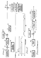
- Fig. 1 is a block diagram of a first embodiment of the present invention;
- Fig. 1A is a block diagram of a communication channel that includes a matched filter;
- Fig. 2 is a graphical showing of power density spectra, all on the same frequency base, of signals provided in the embodiment of Fig. 1;
- Fig. 3 is a block diagram of a medium estimator in the embodiment of Fig. 1;
- Fig. 4 is a block diagram of a correlator in the medium estimator of Fig. 3;
- Fig. 5 is a graphical showing of an output of the correlator of Fig. 4;
- Fig. 6 is a block diagram of a down converter in the medium estimator of Fig. 3;
- Fig. 7 is a graphical showing of a transform relationship utilized in the embodiment of Fig. 1;
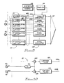
- Fig. 8 is a block diagram of a second embodiment of the present invention;
- Fig. 8A is a block diagram of a medium of transmission in the embodiment of Fig. 8;
- Fig. 9 is a block diagram of a medium estimator in the embodiment of Fig. 8;
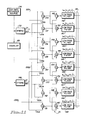
- Fig. 10 is a block diagram of a correlator in the medium estimator of Fig. 9; and
- Fig. 11 is a block diagram of a down converter in the medium estimator of Fig. 9.
- A first of two embodiments is included herein to present the teachings of the invention without a confusing amount of detail. A concept germane to both embodiments is that of matched filtering. As shown in Fig. 1A, a data pulse source 10A provides data pulses of either positive or negative polarity. The polarity is in accordance with an encoding of information represented by the pulses.
- The pulses are transmitted through a medium 14A that has a transfer function H(w). The output of
medium 14A is provided to one of two inputs of anadder 16A. The other input ofadder 16A is connected to anoise source 18A.Adder 16A provides a signal substantially equal to the sum of signals respectively applied to its inputs. Hence, at the output ofadder 16A there is a signal that is corrupted by noise. - A matched
filter 20A includes an equalizer network 22A that is connected to the output ofadder 16A, whereby the signal at the output ofadder 16A is applied to the input of matchedfilter 20A. Equalizer 22A has a transfer function represented by the term H*(w) that is the complex conjugate of the transfer function ofmedium 14A. - The output of equalizer 22A is connected to an integrate and dump
circuit 24A. During a pulse period,circuit 24A provides a signal representative of the average amplitude of a signal applied at its input. At the end of the pulse period,circuit 24A is made to provide an initial a value signal representative of zero. - It should be understood that matched
filter 20A provides an output having an enhanced signal to noise ratio. It should also be understood that when noise provided bysource 18A is of sufficiently low amplitude, the transfer function, H(w), may be accurately determined by measurements, thereby readily enabling construction of equalizer 22A. Conversely, whensource 18A provides a high noise level, construction of equalizer 22A is difficult. The embodiments herein relate to construction of a matched filter for a cyclostationary signal. - As shown in Fig. 1, in the first embodiment, a
multiplier circuit 12 has two inputs, one of which is connected to abaseband generator 14. As shown graphically in Fig. 2(a),baseband generator 14 provides a signal having a baseband power density spectrum. - The other input of
multiplier 12 is connected to the output of a reference spreadspectrum sequence generator 16a (Fig. 1) that generates a spreading signal.Multiplier 12 is a well-known type of circuit that provides a signal having an amplitude proportional to the product of two signals respectively applied to its inputs. Therefore, in response to the baseband signal and the spreading signal,multiplier 12 provides a signal having a spread baseband power density spectrum graphically represented in Fig. 2(b). - The output of multiplier 12 (Fig. 1) is coupled to a
propagation medium 18. The output ofmedium 18 is coupled to one of two inputs of anadder 19. The other input ofadder 19 is connected to a source ofnoise 20.Adder 19 is similar to adder 16A described in connection with Fig. 1A. Accordingly, at the output ofadder 19, there is a propagated spread baseband signal that is corrupted by noise. The output ofadder 19 is referred to hereinafter as a received signal. It should be understood that noise produced bysource 20 may be atmospheric noise, receiver noise, or any other noise that is introduced in a communication channel. - The output of
adder 19 is connected to amedium estimator 22.Medium estimator 22 generates correlation signals representative of components of the autocorrelation of the received signal.Medium estimator 22 is connected to one of two inputs of asimulator 24, whereby the correlation signals are provided tosimulator 24. According to the present invention,simulator 24 utilizes only the correlation signals to generate a representation of coefficients in an equation of a model of the transfer characteristics ofmedium 18. In other words, the model is an estimate of the transfer characteristics ofpropagation medium 18. - The other input of
simulator 24 is coupled to a localspread sequence generator 16b through atime delay network 26. It should be understood thatsequence generators Time delay network 26 provides a delay for synchronizing the output ofgenerator 16b to the received signal. - Unlike the matched filter of Fig. 1A that modifies the output of
adder 16a (a received signal),simulator 24 modifies the output ofgenerator 16b of Fig. 1. Because the output ofgenerator 16b of Fig. 1 is modified, the transfer function, rather than its complex conjugate is utilized in this embodiment. - The output of
adder 19 is connected to one of two inputs of amultiplier unit 28. The other input ofmultiplier 28 is connected to the output ofsimulator 24.Multiplier 28 is similar tomultiplier 12 described hereinbefore. According to the present invention,simulator 24 has transfer characteristics similar to those ofmedium 18. Therefore, the output ofsimulator 24 is a modified local spreading signal that causesmultiplier 28 to provide on an output signal line 30 a recovered baseband signal with an enhanced signal to noise ratio. - The present invention is predicated upon a Fourier transform relationship between a correlation of the output of
medium 18 and the transfer function ofmedium 18. The transform relationship is given as:
where Cn(τk) is the autocorrelation of the output ofmedium 18, with a correlation delay, τk;
n is an index of harmonics of the chip rate;
wn is the radian frequency of the nth harmonic of the chip rate;
w is a radian frequency;
T is the spread period;
τs is a timing synchronization offset;
P(w) is the Fourier transform of a pulse provided bygenerator 16a; and
P*(w) is the complex conjugate of P(w);
H(w) is the transfer function ofmedium 18; and
H*(w) is the complex conjugate of H(w). - The term τs is more fully explained hereinafter.
- The transform relationship is a variation of a generalized equation in "Generalized Cross-Spectrum Symbol Synchronization" by R. McCallister, which is a doctoral thesis written in 1981 at Arizona State University. It should be understood that the transform relationship is that of a Fourier transform pair.
- As shown in Fig. 3,
medium estimator 22 includes a plurality ofcorrelation units 36 respectively connected to a plurality ofdown converters 38 through a plurality of signal lines 40. As explained hereinafter, each ofconverters 38 provide signals representative of two of the terms, Cn(τk) of the transform relationship, where: - n = 1
- for one of the two terms; and
- n = 2
- for the other term.
- As shown in Fig. 4, a
typical correlation unit 42 is comprised of atime delay network 46 that has its input connected to the output ofadder 19. Additionally, amultiplier unit 48 has one of its two inputs connected to the output ofadder 19. The other input ofmultiplier 48 is connected to the output ofdelay network 46. -
Delay network 46 is a well-known type of circuit that provides an output substantially the same as an input signal applied thereto, but delayed by a known time. Accordingly, the output ofdelay network 46 is a delayed received signal.Delay network 46 provides the correlation delay τ₁ forunit 42. -
Multiplier 48 is similar tomultiplier 12 described hereinbefore. The output ofmultiplier 48 has a component proportional to the autocorrelation of the received signal, with the correlation delay τ₁ and a noise component. - The noise component of the output of the
multiplier 48 is spectrally diffuse, with power within a given noise bandwidth directly proportional to the noise bandwidth. Unlike the noise component, the τ₁ correlation signal component is spectrally discrete, with power at harmonics of the chip rate. In other words, the power at any given harmonic is completely contained within any bandwidth about the given harmonic. - The output of
multiplier 48 is connected to alow pass filter 52 at its input.Filter 52 provides the τ₁ correlation signal, while eliminating much of the noise referred to hereinbefore. - As shown in Fig. 5, the τ₁ correlation signal includes a group of
signals 56, each at a frequency that is a harmonic of the chip rate.Signals medium 18. In this embodiment, only the first and second harmonics are utilized. -
Converters 38 are additionally connected to a chiprate reference source 58 that generates a sinusoidal signal having a frequency equal to the chip rate. The timing synchronization offset τs referred to in connection with the transform relationship, is a timing difference between the fundamental frequency component of the spreading signal transmitted throughmedium 18 and the signal generated bysource 58. -
Source 58 is connected to the input of afrequency doubler 69. The output ofdoubler 69 is connected toconverters 38.Doubler 69 generates a sinusoidal signal having a frequency of twice the chip rate. Frequency doublers are well-known in the art. - As shown in Fig. 6,
converters 38 include atypical converter 57 which is similar to all others ofconverters 38.Converter 57 includes a hybrid 63 that has its input connected tosource 58.Hybrid 63 is a well-known type of network that has an output that provides an in-phase (zero degree) output signal, substantially the same as a signal applied at its input.Hybrid 63 additionally has an output that provides a quadrature output signal that is phase shifted by 90 degrees. - The in-phase output of
hybrid 63 is connected to amultiplier unit 62 at one of two inputs thereof. The other input ofmultiplier 62 is connected to the output ofunit 42, whereby the τ₁ correlation signal is applied tomultiplier 62.Multiplier 62 is similar tomultiplier 12 described hereinbefore. - Because the frequency of the output of
source 58 equals the chip rate,multiplier 62 down converts an in-phase component of the τ₁ correlation signal to provide a DC voltage, referred to as a first harmonic τ₁ in-phase estimator signal, and noise. The first harmonic τ₁ in-phase estimator signal is represented by the term Re{C₁(τ₁)}. - The output of
multiplier 62 is connected to a low pass filter 64 at its input. Filter 64 rejects the noise produced bymultiplier 62. - The output of
unit 42 is additionally connected to amultiplier unit 66 at one of two inputs thereof whereby the correlation signal is applied tomultiplier 66.Multiplier 66 is similar tomultiplier 12 described hereinbefore. The other input ofmultiplier 66 is connected to the quadrature output ofhybrid 63. For reasons analogous to those stated in connection with the in-phase estimator signal,multiplier 66 down converts a quadrature component of the correlation signal to provide a DC voltage, referred to as a first harmonic τ₁ quadrature estimator signal, and noise. The first harmonic τ₁ quadrature estimator signal is represented by the term Im{C₁(τ₁)}. - The output of
multiplier 66 is connected to a low pass filter 68 at its input. Filter 68, similar to filter 64, rejects the noise produced bymultiplier 66. - The output of
doubler 69 is connected to a hybrid 65 at its input.Hybrid 65 is similar to hybrid 63 described hereinbefore. The in-phase output ofhybrid 65 is connected to one of two inputs of amultiplier unit 70. The other input ofmultiplier 70 is connected to the output ofunit 42 whereby the correlation signal is applied tomultiplier 70.Multiplier 70 is similar tomultiplier 12 described hereinbefore. - The output of
multiplier 70 is connected to alow pass filter 72 at its input. For reasons corresponding to those given in connection with filter 64,filter 72 provides a substantially noise-free, second harmonic τ₁ in-phase estimator signal represented by the term Re{C₂(τ₁)}. - The quadrature output of
hybrid 65 is connected to amultiplier unit 74 at one of two inputs thereof. The other input ofmultiplier 74 is connected to the output ofunit 42 whereby the τ₁ correlation signal is applied tomultiplier 74.Multiplier 74 is similar tomultiplier 12 described hereinbefore. - The output of
multiplier 74 is connected to alow pass filter 76 at its input. For reasons given in connection with filter 68,filter 76 provides a substantially noise-free, second harmonic τ₁ quadrature estimator signal represented by the term Im{C₂(τ₁)}. In a manner similar to that described hereinbefore, other correlation signals are utilized by converters 38 (Fig. 3) to provide a representation of the terms Cn(τk). - As shown in Fig. 7, a representation of the outputs of
converters 38 are points with equal abscissa intervals therebetween. Abscissa values of the points are representative of delay times respectively associated with the time delay networks ofcorrelation units 36. Because of the transform relationship, an interval 78a between points having adjacent abscissa values map into an interval 80a, with amaximum frequency 82a. It should be understood that the sizes of intervals 78a, 80a are inversely related. Accordingly, interval 78a is a choice based upon bandwidth considerations. - Correspondingly, an interval 78a between points having adjacent abscissa values map into an
interval 80b. Like intervals 78a, 80a,intervals interval 78b is a choice based upon a desired resolution of medium transfer characteristics. -
Converters 38 are connected through a plurality ofsignal lines 84 to simulator 24 (Fig. 1). Withinsimulator 24, a functional relationship is modeled as an approximation of the transfer characteristics ofmedium 18. As explained hereinafter, coefficients in the functional relationship are iteratively adjusted to reduce the difference between the representation of the terms Cn(τk) and a corresponding representation of terms obtained by a computation utilizing the transform and the functional relationships. In this embodiment, the functional relationship is given as:
where Hm(w) is the mth iterative transfer function;
εim is the mth iterative value of the ith numerator coefficient;
λim is the mth iterative value of the ith denominator coefficient; and
N is the number of coefficients, εi or λi, utilized in forming the functional relationship. -
Simulator 24 includes a digital computer (not shown) of any suitable type to perform a Fourier transform operation on the model in accordance with the transform relationship given hereinbefore. More particularly, the transform relationship, as it relates to the model, may be written as: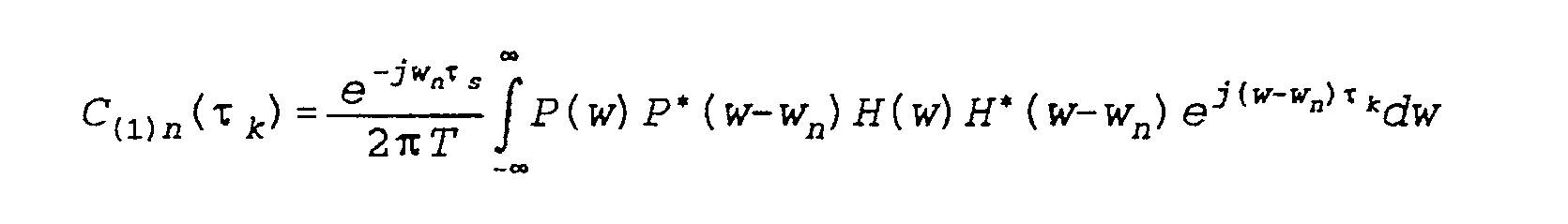
where C(1)n(τk) is the discrete portion of the complex correlation of the output of the model, with a correlation delay τk. The terms C(1)n(τk) are represented by correlation model signals. The computer utilizes the output ofconverters 38 and the model signals to generate a signal representation of a sum square error which is given as:
where E is the sum square error. - The computer iteratively adjusts the numerator and denominator coefficients to reduce the sum square error, thereby providing an estimate, with increased accuracy, of the transfer characteristics of
medium 18. When the sum square error is determined to be less than a threshold level, the coefficients are utilized bysimulator 22 to simulate the transfer characteristics. - In an alternative embodiment, the computer may perform a Fourier transform operation on the estimator signals to produce a set of frequency domain signals that are compared with a signal representation of the model; the difference therebetween is reduced by the iterative adjustment of the coefficients.
- Thus, there is shown hereinabove a simplified embodiment of the present invention.
- As shown in Fig. 8, in a second embodiment of the present invention, a first baseband generator 84a and a
second baseband generator 84b independently generate a first baseband signal and a second baseband signal respectively. The first and second baseband signals both share the baseband power density spectrum (Fig. 2(a)). - The output of generator 84a is connected to a multiplier unit 86a at one of two inputs thereof. The other input of multiplier 86a is connected to the output of
generator 16a. Multiplier 86a is similar tomultiplier 12 described in connection with the first embodiment. Accordingly, multiplier 86a provides a first spread baseband signal having the spread baseband power density spectrum (Fig. 2(b)). - In this embodiment,
generators generators - When the amplitude of the first baseband signal is represented by the term dI(t), and the amplitude of the output of
generator 116a is represented by the term SI(t), the first spread baseband signal is represented by the term dI(t) SI(t). - In a similar manner,
generator 84b is connected to amultiplier unit 86b at one of two inputs thereof. The other input ofmultiplier 86b is connected togenerator 116a. Like multiplier 86a,multiplier 86b is similar tomultiplier 12 described hereinbefore. Hence,multiplier 86b provides a second spread baseband signal having the spread baseband power density spectrum. - When the amplitude of the second baseband signal is represented by the term dQ(t), and the amplitude of the second spread baseband signal is represented by the term SQ(t), the amplitude of the output of
multiplier 86b is represented by the term dQ(t) SQ(t). - An
RF carrier generator 88 has its output connected to the input of a hybrid 90.Generator 88 provides an RF carrier signal used to RF modulate the spread signals provided bymultipliers 86a, 86b in a manner explained hereinafter.Hybrid 90 is similar to hybrid 63 described in connection with the first embodiment. - In response to an RF carrier generated by
generator 88,hybrid 90 provides an in-phase carrier signal, represented by the term cos(wct), and a quadrature carrier signal represented by the term sin(wct), at the in-phase and quadrature outputs thereof, respectively. The in-phase output ofhybrid 90 is connected to amultiplier unit 92 at one of two inputs thereof. The other input ofmultiplier 92 is connected to the output of multiplier 86a.Multiplier 92 is similar tomultiplier 12 described hereinbefore. As shown in Fig. 2(c),multiplier 92 provides an RF modulated signal having a spectrum with a central portion displaced from the origin by the carrier frequency. The output ofmultiplier 92 is a first modulated spread spectrum signal represented by the term dI(t)SI(t)cos(wct). - The quadrature output of
hybrid 90 is connected to amultiplier unit 94 at one of two inputs thereof. The other input ofmultiplier 94 is connected to the output of multiplier 86B. Likemultiplier 92,multiplier 94 is similar tomultiplier 12. Moreover,multiplier 94 provides an RF modulated signal having the power density spectrum with the central portion displaced from the origin. The output ofmultiplier 94 is a second modulated spread spectrum signal represented by the term dQ(t)SQ(t)sin(wct). - The outputs of
multipliers adder 96 at respective inputs thereof. The output ofadder 96 is coupled tomedium 18.Adder 96 is similar toadder 16a. The amplitude of the output ofadder 96 is in accordance with a relationship given as:

where MI is the amplitude of a signal coupled tomedium 18, which is substantially equal to the sum of the amplitudes of the first and second modulated spread spectrum signals. - As shown in Fig. 8A, medium 18 is represented as a filter with
sections 18A, 18B responsive only to input signals represented by terms proportional to cos(wct). The output ofsection 18A is in accordance with a filter relationship which is given as:

where a(t)cos(wct) is representative of a signal applied to the input ofsection 18A; and
⊕ is the convolution operator
- The output of section 18B is in accordance with a filter relationship which is given as:

where a₂(t)sin(wct) is representative of a signal at the output of section 18B; and
HIQ(t) is the transfer function of section 18B. -
Medium 18 additionally includes sections 18C and 18D which respond only to input signals represented by terms proportional to sin(wct). The output of section 18C is in accordance with a filter relationship which is given as:

where b₁(t)sin(wct) is representative of a signal applied to the input of section 18C;
HQQ(t) is the transfer function of section 18C; and
b̂₁(t)sin(wct) is representative of a signal at the output of section 18C. - The output of section 18D is in accordance with a filter relationship which is given as:

where -b₂(t)cos(wct) is representative of a signal at the output of section 18D; and
HQI(t) is the transfer function of section 18D. - It should be understood that the output of
medium 18 is the sum of the outputs ofsections 18A, 18B, 18C, 18D. Additionally, the carat notation ( ̂) is indicative of a distortion that may be caused bymedium 18. - The propagated signal at the output of
adder 96 is utilized to provide the input tomedium 18. When the filter relationships given hereinbefore are utilized, the output ofmedium 18 is given as:

- In this embodiment, the output of
adder 19 is connected to the input of a synchronizedcarrier frequency generator 98, whereby the received signal is applied togenerator 98. The output ofgenerator 98 is a carrier signal synchronized to the output ofgenerator 88. Synchronized carrier generators are well-known to those skilled in the art. - The output of
generator 98 is connected to the input of a hybrid 100.Hybrid 100 is similar tohybrid 63. In a manner similar tohybrid 90,hybrid 100 provides an in-phase synchronized carrier signal represented by the term cos(wct) and a synchronized quadrature carrier signal represented by the term sin(wct) at in-phase and quadrature outputs thereof, respectively. - The in-phase output of
hybrid 100 is connected to amultiplier unit 102 at one of two inputs thereof. The other input ofmultiplier 102 is connected to the output ofadder 19 whereby the received signal is applied tomultiplier 102.Multiplier 102 is similar tomultiplier 12. - Because
multiplier 102 is connected to the in-phase output ofhybrid 100,multiplier 102 synchronously demodulates a portion of the received signal that is in phase with the synchronized carrier signal. More particularly, when the output ofgenerator 20 is neglected, the output ofmultiplier 102 is in accordance with a relationship which is given as:
where M102OUT is the output ofmultiplier 102. - The output of
multiplier 102 is connected to the input of alow pass filter 102A.Filter 102A rejects frequency components greater than the carrier frequency wc. Hence, the output offilter 102A is in accordance with a relationship which is given as:
where M102F is the output offilter 102A. -
Filter 102A provides a first type of in-phase spread spectrum signal. - In a similar manner, the output of
adder 19 is connected to amultiplier unit 104 at one of two inputs thereof. The other input ofmultiplier 104 is connected to the quadrature output ofhybrid 100.Multiplier 104 is similar tomultiplier 12. Therefore,multiplier 104 synchronously demodulates a portion of the received signal that is in quadrance with the synchronized carrier signal. More particularly, when the output ofgenerator 20 is neglected, the output ofmultiplier 104 is in accordance with a relationship which is given as:
where M104OUT is the output ofmultiplier 104. - The output of
multiplier 104 is connected to the input of alow pass filter 104A.Filter 104A rejects frequency components greater than the carrier frequency wc. Hence, the output offilter 104A is in accordance with a relationship which is given as:
where M104F is the output offilter 104A. -
Filter 104A provides a first type of quadrature spread spectrum signal. As explained hereinafter, the first type of in-phase and quadrature spread spectrum signals are utilized to provide a pair of recovered baseband signals that are respectively similar to the first and second baseband signals. - An estimated
carrier frequency generator 106 generates an estimated carrier signal having a frequency approximately equal to the frequency of the signals provided bygenerators generator 106 is connected to the input of a hybrid 108, whereby the estimated carrier is applied tohybrid 108.Hybrid 108 is similar tohybrid 63. - The in-phase output of
hybrid 108 is connected to amultiplier unit 110 at one of two inputs thereof. The other input ofmultiplier 110 is connected to the output ofadder 19 whereby the received signal is applied tomultiplier 110.Multiplier 110 is similar tomultiplier 12. - Because
multiplier 110 is connected to the in-phase output ofhybrid 108,multiplier 110 down converts a portion of the received signal that is in-phase with the estimated carrier signal. Hence,multiplier 110 provides a second type of in-phase spread spectrum signal. - In a similar manner, the output of
adder 19 is connected to amultiplier unit 112 at one of two inputs thereof. The other input ofmultiplier 112 is connected to the quadrature output ofhybrid 108.Multiplier 112 is similar tomultiplier 12. Therefore,multiplier 112 down converts a portion of the received signal that is in quadrature with the estimated carrier signal. Hence,multiplier 112 provides a second type of quadrature spread spectrum signal. - It should be understood that the first and second types of spread spectrum signals differ because unlike
generators generators - The outputs of
multiplier medium estimator 114.Medium estimator 114 utilizes the second type of spread spectrum signals to generate a representation of the coefficients in the equation of the model of the transfer characteristics ofmedium 18. -
Medium estimator 114 is connected to asimulator 116 through a plurality ofsignal lines 118, whereby the signal representation of the coefficients is provided tosimulator 116.Simulator 116 is additionally connected to the output of anadder 103 through a time delay network 26a. The inputs ofadder 103 are connected to the outputs of local spread sequence generators 166a, 166b, respectively. - Generators 166a, 166b are similar to
generators generator 16a. Similarly, generator 166b is synchronized togenerator 116a.Adder 103 and delay network 26a are respectively similar to adder 12 anddelay network 26. - As shown in Fig. 9,
medium estimator 114 is comprised of a plurality ofcorrelation units 115, each of which is connected to the outputs ofmultipliers correlation units 115 are respectively connected to a plurality ofdown converters 120 through a plurality of pairs of signal lines 122. In a manner analogous toconverters 38, each ofconverters 120 provides signal representations of four of the terms of a modified transform relationship which is given as:
where Wo is a difference in frequency betweengenerators - Like
correlation units 36 of the first embodiment, each ofcorrelation units 115 includes the delay network with the unique value of delay. - As shown in Fig. 10,
correlation units 115 include atypical correlation unit 121 comprised ofdelay network 46 with its input connected to the output ofmultiplier 110. Additionally, the output ofmultiplier 110 is connected to amultiplier unit 124 at one of two inputs thereof. The other input ofmultiplier 124 is connected to the output ofdelay network 46. Therefore, the second type of in-phase spread spectrum signal is applied to delaynetwork 46 andmultiplier 124.Multiplier 124 is similar tomultiplier 12. - The output of
delay network 46 is additionally connected to amultiplier unit 126 at one of two inputs thereof. The other input ofmultiplier 126 is connected to the output ofmultiplier 112. Therefore, the second type of quadrature spread spectrum signal is applied tomultiplier 126.Multiplier 126 is similar tomultiplier 12. - The output of
multiplier 124 has a component proportional to an in-phase part of the complex correlation of the received signal with a delay τ₁ and a noise component. Correspondingly, the output ofmultiplier 126 has a component proportional to a quadrature part of the complex correlation of the received signal with a delay τ₁ and a noise component. It should be understood that the τ₁ in-phase and quadrature correlation signals are spectrally discrete, similar to the correlation signals described in connection with the first embodiment. - The outputs of
multipliers Filters multipliers -
Converters 120 are additionally connected to source 58 anddoubler 69 described hereinbefore (Fig. 9).Converters 120 include atypical converter 131 which is similar to all others ofconverters 120. - As shown in Fig. 11,
source 58 is connected withinconverter 131 tohybrid 132 at its input. The in-phase output ofhybrid 132 is connected tomultiplier units multipliers Multipliers multiplier 12.Multipliers - The quadrature output of
hybrid 132 is connected tomultiplier units multipliers unit 121 through signal lines 122a, 122b, respectively.Multipliers multiplier 12.Multipliers - The outputs of
multipliers adder 140.Adder 140 is similar to adder 16A.Adder 140 provides a τ₁ first harmonic estimator signal represented by the term Re{C₋₁(τ₁)} and noise. - The outputs of
multipliers - The outputs of
multipliers adder 144.Adder 144 is similar to adder 16A. Because of the phase of signals applied tomultipliers adder 144 provides a τ₁ first harmonic quadrature estimator signal, represented by the term Im{C₊₁(τ₁)} and noise. - The outputs of
multipliers subtractor 146 at respective inputs thereof.Subtractor 146 is similar to subtractor 89A.Subtractor 146 provides a τ₁ first harmonic quadrature estimator signal, which is represented by the term Im{C₋₁(τ₁)} and noise. - The output of
doubler 69 is connected to a hybrid 148 at its input. The in-phase output of hybrid 148 is connected tomultiplier units multipliers unit 121 through signal lines 122a, 122b, respectively.Multipliers multiplier 12.Multipliers - The quadrature output of hybrid 148 is connected to
multiplier units multipliers unit 121 through signal lines 122a, 122b, respectively.Multipliers multiplier 12.Multipliers - The outputs of
multipliers adder 154.Adder 154 is similar toadder 16a. Because of the phase of signals applied tomultipliers adder 154 provides a τ₁ second harmonic in-phase estimator signal represented by the term Re{C₋₂(τ₁)} and noise. - The outputs of
multipliers subtractor 156 at respective inputs thereof.Subtractor 156 is similar to subtractor 142.Subtractor 156 provides a τ₁ second harmonic in-phase estimator signal represented by the term Re{C₊₂(τ₁)} and noise. - The outputs of
multipliers adder 158.Adder 158 is similar to adder 16A. Because of the phase of signals applied tomultipliers adder 158 provides a τ₁ second harmonic quadrature estimator signal represented by the term Im{C₊₂(τ₁)} and noise. - The outputs of
multipliers subtractor 160 to respective inputs thereof.Subtractor 160 is similar to subtractor 142.Subtractor 160 provides a τ₁ second harmonic quadrature estimator signal represented by the term Im{C₋₂(τ₁)} and noise. - The outputs of
adder 140, subtractor 142,adder 144 andsubtractor 146 are respectively connected to low pass filters 162-165 at their inputs. Filters 162-165 reject the noise provided by multipliers 134-137. The outputs of filters 162-165 are connected tosimulator 116 through some oflines 118 as described hereinafter. - Similarly, the outputs of
adder 154,subtractor 156,adder 158 andsubtractor 160 are respectively connected to low pass filters 166-169 at their inputs. Filters 166-169 reject the noise provided by multipliers 150-153. The outputs of filters 166-169 are connected tosimulator 116 through some oflines 118 as described hereinbefore. - In response to the estimator signals, simulator 116 (Fig. 8) simulates the transfer characteristics of
medium 18.Simulator 116 provides modified first and second spreading signals. The modified first spreading signal is in accordance with a relationship which is given as:

where Ao(t) is representative of the amplitude of the modified first spreading signal. - Correspondingly, the modified second spreading signal is in accordance with a relationship which is given as:

where A₉₀(t) is representative of the amplitude of the modified second spreading signal. - The first modified spreading signal is applied to
multipliers multiplier units 176, 178 at one of two inputs of each, via asignal line 180.Multipliers multiplier 12. - The other inputs of
multipliers multiplier 102. The other inputs ofmultipliers 172, 178 are connected to the output ofmultiplier 104. - The output of
multiplier 170 is in accordance with a relationship which is given as:
where M₁₇₀(t) is representative of the amplitude of the output ofmultiplier 170. - Correspondingly, the output of
multiplier 172 is in accordance with a relationship which is given as:
where M₁₇₂(t) is representative of the amplitude of the output ofmultiplier 172. - The output of
multiplier 176 is in accordance with a relationship which is given as:
where M₁₇₆(t) is representative of the amplitude of the output ofmultiplier 176. - Similarly, the output of multiplier 178 is in accordance with a relationship which is given as:

where M₁₇₈(t) is representative of the amplitude of the output of multiplier 178. - The outputs of
multipliers subtractor 182.Subtractor 182 is similar to subtractor 89A. Moreover, the output ofsubtractor 182 is in accordance with an output relationship which is given as:

where D2OUT(t) is representative of the amplitude of the output ofsubtractor 182. - It should be understood that because the first and second spread sequences differ from each other, terms such as Ŝ₁₂(t) ŜQ1(t), ŜI1(t) ŜQ2(t), ŜQ1(t) ŜI1(t) and ŜQ2(t) ŜI2(t) all integrate to essentially zero over a data pulse period. Moreover, the terms (SQ1(t))² and (SQ2(t))² sum to unity, assuming that medium 18 is lossless. The output of
subtractor 182 is connected to the input of an integrate and dumpcircuit 186 similar tocircuit 24A described hereinbefore. Because of the integration provided bycircuit 186, theoutput circuit 186 reduces to the term dQ(t). - Therefore, in response to the output of
subtractor 182,circuit 186 provides a recovered baseband signal substantially equal to the second baseband signal. - The output of
multipliers 170, 178 are connected to respective inputs of anadder 184.Adder 184 is similar toadder 16a. The output ofadder 184 is connected to an integrate and dumpcircuit 188, similar to circuit 24a. In a manner similar to that described in connection withcircuit 186,circuit 188 provides a recovered baseband signal substantially equal to the first baseband signal. - While the invention has been particularly shown and described with reference to preferred embodiments thereof, it should be understood by those skilled in the art that changes in the form and detail may be made therein without departing from the spirit and scope of the invention.
Although
Claims (31)
- In the method of estimating transfer characteristics of a propagation medium from a cyclostationary signal received therefrom comprising the steps of:
generating a plurality of estimator signals from the received cyclostationary signal, each of which is representative of a spectrally discrete portion of a correlation of said received cyclostationary signal; and
using said plurality of estimator signals to provide an estimate of the transfer characteristics of the medium. - In the method of recovering a baseband signal from a spread spectrum signal received from a propagation medium, said spread spectrum signal being generated by modulating the baseband signal with a reference spreading signal, the steps of:
generating a plurality of estimator signals, each of which is representative of a spectrally discrete portion of a correlation of said received signal;
providing a representation of an assumed set of values of coefficients of an equation of the transfer function of a model that is an estimate of the transfer characteristics of the medium;
generating a plurality of model signals, respectively corresponding to said estimator signals, in accordance with a relationship between a discrete portion of the correlation of the output of said model and the transfer function of said model;
iteratively adjusting said values to reduce differences between said estimator signals and said respectively corresponding model signals; and
providing a local spreading signal synchronized to said reference spreading signal, that is modified in accordance with the estimated transfer function. - In the method of Claim 1 or 2 wherein the step of generating said estimator signals includes the step of generating a correlation signal proportional to the correlation of said received signal with a known correlation delay.
- In the method of Claim 1 or 2 wherein the step of generating said estimator signals includes the step of filtering out spectrally diffuse noise.
- In the method of Claim 3 wherein the step of generating said correlation signal includes the step of delaying said received cyclostationary signal by said correlation delay to provide a delayed received signal, said correlation signal being proportional to the product of the amplitude of said delayed received signal and the amplitude of said received signal.
- In the method of Claim 3 wherein the step of generating said estimator signals includes the step of down converting to DC a spectrally discrete component of said correlation signal that is in-phase with a harmonic of the chip rate of said received signal.
- In the method of Claim 3 wherein the step of generating said estimator signals includes the step of demodulating a spectrally discrete component of said correlation signal that is in quadrature with a harmonic of the received signal.
- The method of Claim 1 or 2 wherein said estimate is provided by the following equation:

T is the clock period of the received signal;
n is an index of harmonics of the clock rate;
w is radian frequency;
wn is the radian frequency of the nth harmonic of the clock rate;
τs is a timing synchronization error;
P(w) is the Fourier transform of the baseband signal;
P*(w-wn) is the complex conjugate of P(w-wn);
Hm(w) is the transfer function of the model; and
Hm*(w-wn) is the complex conjugate of Hm(w-wn). - The method of Claim 1 or 2 wherein said estimate is given as Hm(w) which is defined as follows:

εm is the mth iterative value of the ith numerator coefficient;
λim is the mth iterative value of the ith denominator coefficient; and
N is the number of coefficients εi or λi utilized in forming said estimate. - In the method of Claim 1 or 2 wherein the received signal is multiplied by an estimated radio frequency carrier signal including the steps of:
generating an in-phase received signal proportional to the product of the amplitude of an in-phase component of an estimated carrier signal and the amplitude of said received signal; and
generating a quadrature received signal proportional to the product of the amplitude of a quadrature component of said estimated carrier signal and the amplitude of said received signal. - In the method of Claim 10 wherein the step of generating said estimator signals includes the step of generating a signal proportional to an in-phase part of the complex correlation of said received signal with a known correlation delay.
- In the method of Claim 11 wherein the step of generating said in-phase complex correlation signal includes the step of delaying said in-phase received signal by said correlation delay to provide a delayed in-phase received signal, said in-phase complex correlation signal being proportional to the product of the amplitude of said delayed in-phase received signal and the amplitude of said in-phase received signal.
- In the method of Claim 10 wherein the step of generating said estimator signals includes the step of generating a signal proportional to a quadrature part of the complex correlation of said received signal with a known correlation delay.
- In the method of Claim 13 wherein the step of generating said quadrature complex correlation signal includes the step of delaying said in-phase received signal by said correlation delay, to provide a delayed in-phase received signal, said quadrature correlation signal being proportional to the product of the amplitude of said delayed in-phase received signal and the amplitude of said quadrature received signal.
- In the method of Claim 10 wherein the carrier frequency of said received signal and the frequency of said estimated carrier signal are of the same frequency.
- Apparatus for providing an estimate of transfer characteristics of a propagation medium from a cyclostationary signal received therefrom comprising, in combination:
means for generating a plurality of estimator signals from the received cyclostationary signal, each of which is representative of a spectrally discrete portion of a correlation of said received signal; and
means for using said plurality of estimator signals to provide an estimate of the transfer characteristics of the medium. - The apparatus of Claim 16 wherein said generating means includes means for generating a correlation signal proportional to the correlation of said received signal with a known correlation delay.
- The apparatus of Claim 16 wherein said generating means includes means for filtering out noise that is spectrally diffuse.
- The apparatus of Claim 17 wherein said means for generating said correlation signal comprises:
a time delay network having an input where said received signal is applied, said network providing an output substantially the same as an input signal applied thereto, but delayed by a known time; and
a multiplier unit having one of two inputs for said received signal, the output of said network being connected to the other input, said correlation signal being provided at the output of said multiplier with a correlation delay substantially equal to said known time. - The apparatus of Claim 17 wherein said generating means includes means for down converting to DC a spectrally discrete component of said correlation signal that is in-phase with a harmonic of a clock rate of said received signal.
- The apparatus of Claim 17 wherein said generating means includes means for down converting to DC a spectrally discrete component of said correlation signal that is in quadrature with a harmonic of a clock rate of said received signal.
- The apparatus of Claim 16 wherein said estimate is provided by the following equation:

T is the clock period;
n is an index of harmonics of the clock rate;
w is radian frequency;
τs is a timing synchronization error;
P(w) is the Fourier transform of the baseband signal;
P*(w-wn) is the complex conjugate of P(w-wn);
Hm*(w-wn) is the complex conjugate of Hm(w-wn;
Hm(w) is the estimate of the transfer function of the medium. - The apparatus of Claim 16 wherein said estimate is given as Hm(w) which is defined as follows:

εm is the mth iterative value of the ith denominator coefficient;
λim is the mth iterative value of the ith denominator coefficient; and
N is the number of coefficients εi or λi utilized in forming said estimate. - The apparatus of Claim 16 wherein the received signal is multiplied by an estimated radio frequency carrier signal;
means for generating an in-phase received signal proportional to the product of the amplitude of an in-phase component of an estimated carrier signal and the amplitude of a signal received from said medium; and
means for generating a quadrature received signal proportional to the product of the amplitude of a quadrature component of said estimated carrier signal and the amplitude of said received signal. - The apparatus of Claim 24 wherein said generating means includes means for generating a signal proportional to an in-phase part of the complex correlation of said received signal with a known time delay.
- The apparatus of Claim 25 wherein said generating means comprises:
a time delay network having an input where said in-phase received signal is applied, said network providing an output substantially the same as an input signal applied thereto, but delayed by a known time; and
a multiplier unit having one of two inputs where said in-phase received signal is applied, the output of said delay network being connected to the other input of said multiplier, the output of said multiplier being an in-phase portion of the complex correlation of said received signal with a correlation delay of said known time. - The apparatus of Claim 26 wherein said generating means comprises:
a multiplier unit having one of two inputs where said quadrature received signal is applied, the output of said delay network being connected to the other input of said multiplier, the output of said multiplier being a quadrature portion of the complex correlation of said received signal with a correlation delay of said known time. - The apparatus of Claim 27 wherein said generating means comprises:
means for down converting to DC a part of said in-phase portion of said complex correlation signal that is in-phase with a harmonic of the clock rate of said received signal;
means for down converting to DC a part of said in-phase portion of said complex correlation signal that is in quadrature with said harmonic of the clock rate of said received signal;
means for down converting to DC a part of said quadrature portion of said complex correlation signal that is in-phase with said harmonic of the clock rate of said received signal; and
means for down converting to DC a part of said quadrature portion of said complex correlation signal that is in quadrature with said harmonic of the clock rate of said received signal. - The apparatus of Claim 27 wherein at least one of said down converting means comprises a multiplying unit.
- A matched filter for received spread signals that are demodulated by sequences provided by first and second spread sequence generators, respectively, to provide first and second spread baseband signals, said sequences being of the same chip rate but differing from each other, comprising:
generating means for providing an in-phase RF carrier signal and a quadrature RF carrier signal that are phase shifted 90 degrees from each other;
means for down converting said received spread signals with said in-phase and quadrature RF signals, respectively, to provide a pair of first and second baseband spread spectrum signals, said down converting means being adapted for coupling to a medium through which said received spread spectrum signals are propagated;
estimating means coupled to said medium for generating a representation of the coefficients of an equation of a model of the transfer characteristics of said medium;
simulation means for providing first and second spreading signals that are modified by said model; and
recovery means for providing first and second recovered baseband signals in response to said spreading signals and said first and second baseband spread spectrum signals. - Apparatus for providing an estimate of transfer characteristics of a propagation medium from cyclostationary signal received therefrom comprising, in combination:
means for generating a plurality of estimator signals from the received cyclostationary signal, each of which is representative of a spectrally discrete portion of a correlation of said received signal; and
means for using said plurality of estimator signals to provide an estimate of the transfer characteristics of the medium, said apparatus including a matched filter for received spread signals that are demodulated by sequences provided by first and second spread sequence generators, respectively, to provide first and second spread baseband signals, said sequences being of the same chip rate but differing from each other, comprising:
generating means for providing an in-phase RF carrier signal and a quadrature RF carrier signal that are phase shifted 90 degrees from each other;
means for down converting said received spread signals with said in-phase and quadrature RF signals, respectively, to provide a pair of first and second baseband spread spectrum signals, said down converting means being adapted for coupling to a medium through which said received spread spectrum signals are propagated;
estimating means coupled to said medium for generating a representation of the coefficients of an equation of a model of the transfer characteristics of said medium;
simulation means for providing first and second spreading signals that are modified by said model; and
recovery means for providing first and second recovered baseband signals in response to said spreading signals and said first and second baseband spread spectrum signals.
Applications Claiming Priority (1)
| Application Number | Priority Date | Filing Date | Title |
|---|---|---|---|
| US07/142,707 US4922506A (en) | 1988-01-11 | 1988-01-11 | Compensating for distortion in a communication channel |
Publications (1)
| Publication Number | Publication Date |
|---|---|
| EP0454913A1 true EP0454913A1 (en) | 1991-11-06 |
Family
ID=22500960
Family Applications (1)
| Application Number | Title | Priority Date | Filing Date |
|---|---|---|---|
| EP90304667A Withdrawn EP0454913A1 (en) | 1988-01-11 | 1990-04-30 | Compensating for distortion in a communication channel |
Country Status (2)
| Country | Link |
|---|---|
| US (1) | US4922506A (en) |
| EP (1) | EP0454913A1 (en) |
Cited By (2)
| Publication number | Priority date | Publication date | Assignee | Title |
|---|---|---|---|---|
| EP0806079A1 (en) * | 1994-09-09 | 1997-11-12 | Omnipoint Corporation | Transmission and reception of cpm spread-spectrum communications |
| WO2004079953A1 (en) * | 2003-03-07 | 2004-09-16 | Technische Universität Dresden | Method and arrangement for transmitting signals according to a multiple access method |
Families Citing this family (75)
| Publication number | Priority date | Publication date | Assignee | Title |
|---|---|---|---|---|
| US5029180A (en) * | 1989-03-23 | 1991-07-02 | Echelon Systems Corporation | Transceiver providing selectable frequencies and spreading sequences |
| US5357541A (en) * | 1989-03-23 | 1994-10-18 | Echelon Corporation | Transceiver providing selectable frequencies and spreading sequences |
| JP2660441B2 (en) * | 1989-07-03 | 1997-10-08 | 双葉電子工業 株式会社 | Receiver for spread spectrum communication |
| US5016256A (en) * | 1989-10-17 | 1991-05-14 | Stewart Clarence H | Spread spectrum intercept apparatus and method |
| US5103460A (en) * | 1989-10-17 | 1992-04-07 | Clarence H. Stewart | Spread spectrum intercept apparatus and method |
| US5265121A (en) * | 1989-10-17 | 1993-11-23 | Juanita H. Stewart | Spread spectrum coherent processor |
| US5113409A (en) * | 1989-10-17 | 1992-05-12 | Stewart Clarence H | Spread spectrum intercept apparatus and method |
| GB2241129B (en) * | 1990-02-16 | 1993-04-07 | Stc Plc | Apparatus for generating complex composite rf signals |
| US5166952A (en) * | 1990-05-24 | 1992-11-24 | Cylink Corporation | Method and apparatus for the reception and demodulation of spread spectrum radio signals |
| US5253268A (en) * | 1990-05-24 | 1993-10-12 | Cylink Corporation | Method and apparatus for the correlation of sample bits of spread spectrum radio signals |
| US5157686A (en) * | 1990-05-24 | 1992-10-20 | Cylink Corporation | Method and apparatus for the modulation of spread spectrum radio signals |
| JPH07118668B2 (en) * | 1990-06-15 | 1995-12-18 | 双葉電子工業株式会社 | Spread spectrum communication system |
| US5103459B1 (en) * | 1990-06-25 | 1999-07-06 | Qualcomm Inc | System and method for generating signal waveforms in a cdma cellular telephone system |
| US6693951B1 (en) * | 1990-06-25 | 2004-02-17 | Qualcomm Incorporated | System and method for generating signal waveforms in a CDMA cellular telephone system |
| US6873643B2 (en) | 1990-11-16 | 2005-03-29 | Interdigital Technology Corporation | Spread spectrum adaptive power control communications system and method |
| US5535238A (en) | 1990-11-16 | 1996-07-09 | Interdigital Technology Corporation | Spread spectrum adaptive power control communications system and method |
| US5299226A (en) * | 1990-11-16 | 1994-03-29 | Interdigital Technology Corporation | Adaptive power control for a spread spectrum communications system and method |
| US5228056A (en) * | 1990-12-14 | 1993-07-13 | Interdigital Technology Corporation | Synchronous spread-spectrum communications system and method |
| US5703874A (en) | 1990-12-05 | 1997-12-30 | Interdigital Technology Corporation | Broadband CDMA overlay system and method |
| US5351269A (en) * | 1990-12-05 | 1994-09-27 | Scs Mobilecom, Inc. | Overlaying spread spectrum CDMA personal communications system |
| US5185762A (en) * | 1991-05-15 | 1993-02-09 | Scs Mobilecom, Inc. | Spread spectrum microwave overlay with notch filter |
| US5161168A (en) * | 1991-05-15 | 1992-11-03 | Scs Mobilecom, Inc. | Spread spectrum CDMA communications system microwave overlay |
| US5506864A (en) * | 1990-12-05 | 1996-04-09 | Interdigital Technology Corporation | CDMA communications and geolocation system and method |
| US5263045A (en) * | 1990-12-05 | 1993-11-16 | Interdigital Technology Corporation | Spread spectrum conference call system and method |
| US7020125B2 (en) * | 1990-12-05 | 2006-03-28 | Interdigital Technology Corporation | Broadband CDMA overlay system and method |
| US5274665A (en) * | 1990-12-14 | 1993-12-28 | Interdigital Technology Corporation | Polyopoly overlapping spread spectrum communication system and method |
| USRE38627E1 (en) * | 1991-05-15 | 2004-10-19 | Interdigital Technology Corp. | High capacity spread spectrum channel |
| US5166951A (en) * | 1991-05-15 | 1992-11-24 | Scs Mobilecom, Inc. | High capacity spread spectrum channel |
| US5228053A (en) * | 1991-05-15 | 1993-07-13 | Interdigital Technology Corporation | Spread spectrum cellular overlay CDMA communications system |
| US5164958A (en) * | 1991-05-22 | 1992-11-17 | Cylink Corporation | Spread spectrum cellular handoff method |
| US5235615A (en) * | 1991-05-22 | 1993-08-10 | Cylink Corporation | Spread spectrum method |
| US5495497A (en) * | 1991-09-25 | 1996-02-27 | The United States Of America As Represented By The Secretary Of The Navy | Method and apparatus for suppressing interference from bandspread communication signals |
| US5495496A (en) * | 1991-09-26 | 1996-02-27 | The United States Of America As Represented By The Secretary Of The Navy | Method and apparatus for suppressing linear amplitude interference from bandspread communication signals |
| US5345467A (en) * | 1991-07-10 | 1994-09-06 | Interdigital Technology Corp. | CDMA cellular hand-off apparatus and method |
| US5175744A (en) * | 1991-11-22 | 1992-12-29 | Bell Communications Research, Inc. | Spread-time code division multiple access technique with arbitrary spectral shaping |
| US5173923A (en) * | 1991-11-22 | 1992-12-22 | Bell Communications Research, Inc. | Spread-time code division multiple access technique with arbitrary spectral shaping |
| US5177768A (en) * | 1991-11-22 | 1993-01-05 | Bell Communications Research, Inc. | Spread-time code division multiple access technique with arbitrary spectral shaping |
| US5175743A (en) * | 1991-11-22 | 1992-12-29 | Bell Communications Research, Inc. | Spread-time code division multiple access technique with arbitrary spectral shaping |
| US5461610A (en) * | 1992-08-31 | 1995-10-24 | At&T Ipm Corp. | Precoding of signature sequences for CDMA systems |
| US5553081A (en) * | 1994-04-08 | 1996-09-03 | Echelon Corporation | Apparatus and method for detecting a signal in a communications system |
| WO1996011527A1 (en) * | 1994-10-07 | 1996-04-18 | Massachusetts Institute Of Technology | Quadrature sampling system and hybrid equalizer |
| US6108368A (en) * | 1995-12-29 | 2000-08-22 | Echelon Corporation | Adaptive reference pattern for spread spectrum detection claims |
| EP0813315A3 (en) * | 1996-06-13 | 1998-06-10 | Canon Kabushiki Kaisha | Spread spectrum QAM transmission |
| US6430216B1 (en) | 1997-08-22 | 2002-08-06 | Data Fusion Corporation | Rake receiver for spread spectrum signal demodulation |
| US6252535B1 (en) | 1997-08-21 | 2001-06-26 | Data Fusion Corporation | Method and apparatus for acquiring wide-band pseudorandom noise encoded waveforms |
| US6049573A (en) * | 1997-12-11 | 2000-04-11 | Massachusetts Institute Of Technology | Efficient polyphase quadrature digital tuner |
| EP1383490B1 (en) * | 2001-03-14 | 2012-04-25 | Bristol-Myers Squibb Company | Combination of an epothilone analog and chemotherapeutic agents for the treatment of proliferative diseases |
| US6952445B2 (en) * | 2001-08-14 | 2005-10-04 | Murphy Charles D | Symbol constellations having second-order statistics with cyclostationary phase |
| WO2003023444A1 (en) | 2001-09-12 | 2003-03-20 | Data Fusion Corporation | Gps near-far resistant receiver |
| US7158559B2 (en) * | 2002-01-15 | 2007-01-02 | Tensor Comm, Inc. | Serial cancellation receiver design for a coded signal processing engine |
| US8085889B1 (en) | 2005-04-11 | 2011-12-27 | Rambus Inc. | Methods for managing alignment and latency in interference cancellation |
| US7260506B2 (en) * | 2001-11-19 | 2007-08-21 | Tensorcomm, Inc. | Orthogonalization and directional filtering |
| US7787518B2 (en) * | 2002-09-23 | 2010-08-31 | Rambus Inc. | Method and apparatus for selectively applying interference cancellation in spread spectrum systems |
| US20050101277A1 (en) * | 2001-11-19 | 2005-05-12 | Narayan Anand P. | Gain control for interference cancellation |
| US20040208238A1 (en) * | 2002-06-25 | 2004-10-21 | Thomas John K. | Systems and methods for location estimation in spread spectrum communication systems |
| US7808937B2 (en) | 2005-04-07 | 2010-10-05 | Rambus, Inc. | Variable interference cancellation technology for CDMA systems |
| US7787572B2 (en) * | 2005-04-07 | 2010-08-31 | Rambus Inc. | Advanced signal processors for interference cancellation in baseband receivers |
| US8761321B2 (en) * | 2005-04-07 | 2014-06-24 | Iii Holdings 1, Llc | Optimal feedback weighting for soft-decision cancellers |
| US20050180364A1 (en) * | 2002-09-20 | 2005-08-18 | Vijay Nagarajan | Construction of projection operators for interference cancellation |
| US7463609B2 (en) * | 2005-07-29 | 2008-12-09 | Tensorcomm, Inc | Interference cancellation within wireless transceivers |
| US7876810B2 (en) | 2005-04-07 | 2011-01-25 | Rambus Inc. | Soft weighted interference cancellation for CDMA systems |
| US7577186B2 (en) * | 2002-09-20 | 2009-08-18 | Tensorcomm, Inc | Interference matrix construction |
| US20050123080A1 (en) * | 2002-11-15 | 2005-06-09 | Narayan Anand P. | Systems and methods for serial cancellation |
| US8179946B2 (en) * | 2003-09-23 | 2012-05-15 | Rambus Inc. | Systems and methods for control of advanced receivers |
| US8005128B1 (en) | 2003-09-23 | 2011-08-23 | Rambus Inc. | Methods for estimation and interference cancellation for signal processing |
| CN1723627A (en) * | 2002-10-15 | 2006-01-18 | 张量通讯公司 | Method and apparatus for channel amplitude estimation and interference vector construction |
| WO2004036811A2 (en) * | 2002-10-15 | 2004-04-29 | Tensorcomm Inc. | Method and apparatus for interference suppression with efficient matrix inversion in a ds-cdma system |
| WO2004042948A1 (en) * | 2002-10-31 | 2004-05-21 | Tensorcomm, Incorporated | Systems and methods for reducing interference in cdma systems |
| WO2004073159A2 (en) * | 2002-11-15 | 2004-08-26 | Tensorcomm, Incorporated | Systems and methods for parallel signal cancellation |
| US7477710B2 (en) * | 2004-01-23 | 2009-01-13 | Tensorcomm, Inc | Systems and methods for analog to digital conversion with a signal cancellation system of a receiver |
| US20060125689A1 (en) * | 2004-12-10 | 2006-06-15 | Narayan Anand P | Interference cancellation in a receive diversity system |
| WO2006093723A2 (en) * | 2005-02-25 | 2006-09-08 | Data Fusion Corporation | Mitigating interference in a signal |
| US7826516B2 (en) | 2005-11-15 | 2010-11-02 | Rambus Inc. | Iterative interference canceller for wireless multiple-access systems with multiple receive antennas |
| US20060229051A1 (en) * | 2005-04-07 | 2006-10-12 | Narayan Anand P | Interference selection and cancellation for CDMA communications |
| US8837957B2 (en) * | 2012-01-12 | 2014-09-16 | Futurewei Technologies, Inc. | Method and apparatus of using digital equalizer for cascaded wavelength selective switch compensation |
Citations (2)
| Publication number | Priority date | Publication date | Assignee | Title |
|---|---|---|---|---|
| US4669091A (en) * | 1986-02-10 | 1987-05-26 | Rca Corporation | Adaptive multipath distortion equalizer |
| EP0319973A2 (en) * | 1987-12-09 | 1989-06-14 | Nec Corporation | Spread spectrum demodulating device for spread spectrum communication system |
Family Cites Families (13)
| Publication number | Priority date | Publication date | Assignee | Title |
|---|---|---|---|---|
| US3988667A (en) * | 1975-03-06 | 1976-10-26 | Hewlett-Packard Company | Noise source for transfer function testing |
| US4058713A (en) * | 1976-09-20 | 1977-11-15 | General Signal Corporation | Equalization by adaptive processing operating in the frequency domain |
| US4279019A (en) * | 1979-05-15 | 1981-07-14 | California Institute Of Technology | Method and apparatus for delay analysis of energy transmitted through a medium |
| US4365338A (en) * | 1980-06-27 | 1982-12-21 | Harris Corporation | Technique for high rate digital transmission over a dynamic dispersive channel |
| US4361891A (en) * | 1980-12-22 | 1982-11-30 | General Electric Company | Spread spectrum signal estimator |
| US4394744A (en) * | 1981-02-12 | 1983-07-19 | The United States Of America As Represented By The Secretary Of The Navy | Real-time amplitude histogram shaper |
| US4462081A (en) * | 1982-04-05 | 1984-07-24 | System Development Corporation | Signal processing system |
| US4713782A (en) * | 1984-08-23 | 1987-12-15 | Hewlett-Packard Company | Method and apparatus for measuring a transfer function |
| US4654808A (en) * | 1984-08-23 | 1987-03-31 | Hewlett-Packard Company | Noise corrected pole and zero analyzer |
| US4621365A (en) * | 1984-11-16 | 1986-11-04 | Hughes Aircraft Company | Synchronization preamble correlation detector and frequency estimator |
| US4611333A (en) * | 1985-04-01 | 1986-09-09 | Motorola, Inc. | Apparatus for despreading a spread spectrum signal produced by a linear feedback shift register (LFSR) |
| US4807256A (en) * | 1985-12-23 | 1989-02-21 | Texas Instruments Incorporated | Global position system receiver |
| US4774715A (en) * | 1987-03-11 | 1988-09-27 | Telesystems Slw Inc. | Device for demodulating a spread spectrum signal |
-
1988
- 1988-01-11 US US07/142,707 patent/US4922506A/en not_active Expired - Lifetime
-
1990
- 1990-04-30 EP EP90304667A patent/EP0454913A1/en not_active Withdrawn
Patent Citations (2)
| Publication number | Priority date | Publication date | Assignee | Title |
|---|---|---|---|---|
| US4669091A (en) * | 1986-02-10 | 1987-05-26 | Rca Corporation | Adaptive multipath distortion equalizer |
| EP0319973A2 (en) * | 1987-12-09 | 1989-06-14 | Nec Corporation | Spread spectrum demodulating device for spread spectrum communication system |
Non-Patent Citations (1)
| Title |
|---|
| 1989 INTERNATIONAL SYMPOSIUM DIGEST ANTENNAS AND PROPAGATION vol. 2, 26 June 1989, NEW YORK (US) pages 798 - 801; C. TOU: "ADAPTIVE MODELING OF RADIO PROPAGATION CHANNELS " * |
Cited By (3)
| Publication number | Priority date | Publication date | Assignee | Title |
|---|---|---|---|---|
| EP0806079A1 (en) * | 1994-09-09 | 1997-11-12 | Omnipoint Corporation | Transmission and reception of cpm spread-spectrum communications |
| EP0806079A4 (en) * | 1994-09-09 | 1999-10-13 | Omnipoint Corp | Transmission and reception of cpm spread-spectrum communications |
| WO2004079953A1 (en) * | 2003-03-07 | 2004-09-16 | Technische Universität Dresden | Method and arrangement for transmitting signals according to a multiple access method |
Also Published As
| Publication number | Publication date |
|---|---|
| US4922506A (en) | 1990-05-01 |
Similar Documents
| Publication | Publication Date | Title |
|---|---|---|
| EP0454913A1 (en) | Compensating for distortion in a communication channel | |
| EP0332290B1 (en) | Equaliser for radio receiver | |
| DE69533887T2 (en) | Spreizspektrumempfangsgerät | |
| KR100210321B1 (en) | Direct sequence spread spectrum communication system | |
| US4255791A (en) | Signal processing system | |
| US8040935B2 (en) | Methods and apparatus for spread spectrum modulation and demodulation | |
| KR100463682B1 (en) | Method of transmission and device to carry out said method | |
| US5134630A (en) | Method and apparatus for transparent tone-in-band transmitter, receiver and system processing | |
| US3916313A (en) | PSK-FSK spread spectrum modulation/demodulation | |
| JPH0799487A (en) | Spread spectrum communication equipment and radio communication equipment | |
| CA2093566A1 (en) | Radio communication systems | |
| KR100344600B1 (en) | Method and system for generating a complex pseudonoise sequence for processing a code division multiple access signal | |
| US6023488A (en) | Spread spectrum modulation | |
| US5852636A (en) | Method of and apparatus for modulation of FSK carrier in a very narrow band | |
| Sandhu et al. | Investigation on operations of a secure communication system based on the chaotic phase shift keying scheme | |
| US5619527A (en) | Chip-based selective receiving system for a spread spectrum signal | |
| JPH07202751A (en) | Spread spectrum transmission method and spread spectrum transmitter | |
| JP3179554B2 (en) | Spread spectrum communication system | |
| RU2713384C1 (en) | Method of transmitting information using broadband signals | |
| RU2128398C1 (en) | Device for tracing signal delay | |
| Ozluturk | Coherent and noncoherent DS/SSMA communications with complex signature sequences: Error and acquistion performances | |
| JPH1079687A (en) | Delay locked loop | |
| KR100374483B1 (en) | Spreading system using balanced duo-binary encoder and decoder, and its application to spreading method | |
| JPH02132936A (en) | Receiving device for spread spectrum communication | |
| JPS6158338A (en) | Spread spectrum phase encoding power communication system |
Legal Events
| Date | Code | Title | Description |
|---|---|---|---|
| PUAI | Public reference made under article 153(3) epc to a published international application that has entered the european phase |
Free format text: ORIGINAL CODE: 0009012 |
|
| AK | Designated contracting states |
Kind code of ref document: A1 Designated state(s): DE DK ES FR GB IT LU NL SE |
|
| 17P | Request for examination filed |
Effective date: 19920316 |
|
| STAA | Information on the status of an ep patent application or granted ep patent |
Free format text: STATUS: THE APPLICATION HAS BEEN WITHDRAWN |
|
| 18W | Application withdrawn |
Withdrawal date: 19931102 |