EP0457321B1 - Method and apparatus for measuring ion beam collimation, shaping the ion beam and controlling scanning thereof - Google Patents
Method and apparatus for measuring ion beam collimation, shaping the ion beam and controlling scanning thereof Download PDFInfo
- Publication number
- EP0457321B1 EP0457321B1 EP91107947A EP91107947A EP0457321B1 EP 0457321 B1 EP0457321 B1 EP 0457321B1 EP 91107947 A EP91107947 A EP 91107947A EP 91107947 A EP91107947 A EP 91107947A EP 0457321 B1 EP0457321 B1 EP 0457321B1
- Authority
- EP
- European Patent Office
- Prior art keywords
- ion beam
- scanning
- multipoint
- ion
- monitor
- Prior art date
- Legal status (The legal status is an assumption and is not a legal conclusion. Google has not performed a legal analysis and makes no representation as to the accuracy of the status listed.)
- Expired - Lifetime
Links
Images


Classifications
-
- H—ELECTRICITY
- H01—ELECTRIC ELEMENTS
- H01J—ELECTRIC DISCHARGE TUBES OR DISCHARGE LAMPS
- H01J37/00—Discharge tubes with provision for introducing objects or material to be exposed to the discharge, e.g. for the purpose of examination or processing thereof
- H01J37/30—Electron-beam or ion-beam tubes for localised treatment of objects
- H01J37/317—Electron-beam or ion-beam tubes for localised treatment of objects for changing properties of the objects or for applying thin layers thereon, e.g. for ion implantation
- H01J37/3171—Electron-beam or ion-beam tubes for localised treatment of objects for changing properties of the objects or for applying thin layers thereon, e.g. for ion implantation for ion implantation
-
- H—ELECTRICITY
- H01—ELECTRIC ELEMENTS
- H01J—ELECTRIC DISCHARGE TUBES OR DISCHARGE LAMPS
- H01J37/00—Discharge tubes with provision for introducing objects or material to be exposed to the discharge, e.g. for the purpose of examination or processing thereof
- H01J37/30—Electron-beam or ion-beam tubes for localised treatment of objects
- H01J37/304—Controlling tubes by information coming from the objects or from the beam, e.g. correction signals
Definitions
- the present invention relates to a method of measuring collimation of an ion beam and of shaping a form of an ion beam scanning wave according to claims 1 and 3 and to an ion implanter according to claim 6 and particularly to methods and apparatus yielding electrostatically-controlled collimated scanning of a targer using an ion beam in order to implant ions in the target.
- Document US-A-4 494 005 discloses an ion implanter system, wherein ion beam detectors are arranged in front of a substrate that is provided on a rotary disk.
- Document US-A-4 724 324 discloses an ion implanter apparatus that has an array of Faraday current sensors positioned along a line in the path of the beam so that each sensor intercepts a component of the beam.
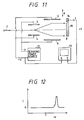
- FIG. 11 A prior art ion implanter is shown in art in Fig. 11.
- ions extracted from an ion source (not shown in Fig. 11), are optionally analyzed by a magnetic field according to isotopic mass, accelerated to a desired energy level, and refocused at a soot in order to form an ion beam 2.
- the ion beam 2 is then deflected for electrostatically-controlled collimated scanning in an X-direction (e.g., horizontal direction X in Fig. 11) by the cooperation of two pairs of scanning electrodes 4 and 6 which are supplied with 180° out-of-phase scanning voltages from a scanning power source 12.
- X-direction e.g., horizontal direction X in Fig. 11
- the deflected ion beam 2 illuminates a target 8 (e.g., a wafer) on a holder 10.
- a target 8 e.g., a wafer
- the scanning power source 12 produces scanning voltages of +V and -V which each have a triangular waveform and which are out of phase by 180°.
- the target 8 is mechanically scanned in a Y-direction (e.g., vertical direction Y in Fig. 11) which is substantially perpendicular to the X-direction by mechanically altering the position of the holder 10 and the target 8 through the use of, for example, a holder drive unit (not shown in Fig. 11).
- This mechanical scanning in the Y-direction when coupled with the electrostatically-controlled collimated scanning in the X-direction achieved through the deflection of ion beam 2 by scanning electrode pairs 4 and 6, allows hybrid scanning in both the X-direction and the Y-direction to be performed.
- ions can be implanted uniformly over the entire surface of the target 8.
- a beam monitor 14 receives the ion beam 2 in order to measure a beam current I.
- the beam monitor 14 is provided at one end of a region where the ion beam 2 is scanned in the X-direction.
- the measured beam current I is fed to the Y-axis of a display 15 and a scanning voltage (e.g., +V) is fed to the X-axis of the display so that the status of scanning performed by using the ion beam 2 is monitored during the ion implantation process.
- a waveform of the beam current I of scanning ion beam 2 is shown in Fig. 12.
- abnormal collimation of the ion beam 2 can occur for various reasons. Such reasons include the failure or deterioration of the scanning power source 12, the breakage or deterioration of the lead wires (not shown in Fig. 11) connecting the scanning power source 12 to the scanning electrodes 4 and 6, and unexpected variations in the configuration of the beam line. If abnormal collimation of the ion beam 2 occurs (i.e., if the ion beam 2 is not well collimated), the scanning speed of the ion beam 2 or the angle of its incidence on the target 8 fluctuates, thereby causing various problems such as lower uniformity in the ion implantation of target 8.
- the operator of the prior art ion implanter must check for abnormal collimation of the ion beam based on the display of the waveform such as shown in Fig. 12.
- many years of experience are required to correctly interpret such a waveform display. Even if the operator is well experienced, for a variety of reasons, it is difficult for the operator to determine whether the collimation of the ion beam is abnormal by observing the waveform display.
- Such reasons include, but are not limited to, the following: (1) long-term variations in the collimation of ion beam 2 are difficult for the operator to locate; (2) even when the downstream scanning electrode 6 becomes completely ineffective, a waveform of beam current I, except for a slight shift in peak position, is identical to the one obtained under normal conditions; (3) depending on the ion species, the beam dose, the ion source and other factors, the waveform of beam current I may normally undergo variations or changes similar to those which occur as a result of abnormal collimation; and (4) even if abnormal collimation occurs, a waveform similar to the waveform for normal collimation is still sometimes obtained when the offset voltage of the scanning power source 12 is changed so as to shift the center of the beam scanning.
- the scanning waveform controlling an ion beam conventionally has been shaped in accordance with either of the following two major techniques or methods:
- method (A) if the beam monitor is not located in the same position as the target, the difference between the two positions (i.e., ⁇ Z) causes the following inequality, with reference to Fig. 5, to result: (X B ' - X B : X A ' - X A ) ⁇ (X B ' - X B : X A ' - X A ).
- Method (B) is disadvantageous in that it involves the construction of a complicated simulation model. Furthermore, it is particularly difficult to evaluate the effects of the edges of the scanning electrodes because such an evaluation requires considerable time to perform correct calculations. Moreover, even if data of preferred scanning waveforms are input into the scanning power source (e.g., arbitrary waveform generator 221 in the power source 22) in accordance with method (B), undesired factors such as the nonlinearity of high voltage amplifiers 222 and 223 can cause the power source 22 to produce an output scanning voltage which does not necessarily agree with the input scanning waveform data and which can vary from one measuring apparatus to another, thereby making it difficult to correctly achieve the shaping of scanning waveforms.
- the scanning power source e.g., arbitrary waveform generator 221 in the power source 22
- the present invention has been made in view of the above circumstances and has as an object to provide a method by which the abnormal collimation of an ion beam can be detected in a simple but reliable way.
- a further object of the present invention is to provide a method by which not only the abnormal collimation of the ion beam is detected, but also shapes the form, or profile, of that ion beam and controls its scanning in such a way that the speed of the scanning of the ion beam over a target approaches or will become a constant value.
- Yet another object of the present invention is to provide an ion implanter which is capable of implementing the methods described above.
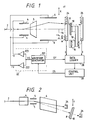
- Fig. 1 is a schematic diagram showing an ion implanter according to an embodiment of the present invention.
- ions extracted from an ion source (not shown in Fig. 1) are optionally analyzed by a magnetic field according to isotope mass, accelerated to a desired energy level, and refocused at a spot in order to form ion beam 2.
- the ion beam 2 is then deflected for electrostatic parallel scanning in an X-direction (e.g., horizontal direction X in Fig. 1) by the cooperation of a pair of upstream scanning electrodes 4 and a pair of downstream scanning electrode 6 which are supplied with 180° out-of-phase scanning voltages from a scanning power source 22. Thereafter, the deflected ion beam 2 illuminates target 8 on a holder 10.
- a pair of deflecting electrodes 5 is provided between the upstream pair of scanning electrodes 4 and the downstream pair of scanning electrode 6.
- the electrodes 5 deflect the ion beam 2 in a Y-direction (e.g., vertical direction Y in Fig. 1 and in Fig. 2) by a predetermined angle (best seen in Fig. 2) so that a neutral beam travelling in a straight path out of the upstream pair of scanning electrodes 4 is separated to permit only the desired ion beam 2 to strike the target 8.
- the deflecting electrodes 5 are also used to permit the ion beam 2 to be fed into a multipoint beam monitor 24 (described below) by changing (i.e., lowering) the voltage applied to these electrodes.
- the target 8 is mechanically scanned in the Y-direction (e.g., vertical direction Y in Fig. 1) which is substantially perpendicular to the X-direction by mechanically altering the position of the holder 10 and the target 8 through the rocking of an arm 18 which supports the holder 10. While in Fig. 1, the arm 18 is rocked in the direction of arrow R by a reversing motor (e.g., a direct drive motor) 16 so that the holder 10 and the target 8 will move in the Y-direction, this is not the only way to move the holder 10 and the target 8 in the Y-direction.
- a reversing motor e.g., a direct drive motor
- two multipoint beam monitors 24 and 26 are positioned, respectively, at an upstream location of the ion beam and at a downstream location of the ion beam such that the monitor 24 is located upstream of the target 8 and the other monitor 26 is located downstream of the target 8. Furthermore, the upstream monitor 24 is offset slightly upward so that it will not block the incidence of the ion beam 2 on the target 8, whereas the downstream monitor 26 is located predominantly behind the target 8, as shown in Fig. 2.
- the multipoint beam monitors 24 and 26 each include a plurality of beam detecting points for electrically detecting the ion beam 2.
- the beam detecting points are positioned on each multipoint beam monitor so that each monitor has the same set of detecting point coordinate values in the X-direction in which the ion beam 2 is scanned and the positions of such beam detecting points are predetermined.
- the multipoint beam monitors 24 and 26 may each be an array of beam current meters (e.g., Faraday cups) which receive the ion beam 2 to measure the beam current I and which are aligned in the X-direction in which the ion beam 2 is scanned.
- a mask having a plurality of holes arranged in the X-direction may be provided in front of a single beam current meter having a longitudinal axis parallel to the X-direction in order to form each of the multipoint beam monitors.
- each of the multipoint beam monitors 24 and 26 is intended to detect a peak of the ion beam current I (as will be described below) so that particularly high precision of measurement is not required for determining the absolute value of beam current I.
- variations in factors such as the amount of detection and sensitivity between different beam current detecting points in each of the beam monitors 24 and 26 will not be serious problems to consider.
- the values of the beam current I measured with the multipoint beam monitors 24 and 26 are collected and recorded with a data logger 28.
- the data logger 28 is connected to a control unit 30 that performs mathematical and other operations to be described below on the basis of the data collected by the data logger 28.
- the scanning power source 22 for supplying scanning voltages +V and -V to the scanning electrodes 4 and 6 is designed to have the following circuit configuration.
- the scanning power source 22 includes a variable waveform generator 221 having a wide range of variation which, in response to applied scanning waveform data (e.g., scanning waveform data DS supplied from the control unit 30), generates a scanning signal VS having a waveform corresponding to the scanning waveform data.
- the scanning power source 22 also includes a high-voltage amplifier 222 that boosts the scanning signal VS to output a scanning voltage +V, and a high-voltage amplifier 223 that boosts the scanning signal VS to output a scanning voltage -V having a polarity opposite to +V.
- the variable waveform generator 221 may be of a known type that is capable of generating signals of a variable waveform in accordance with a preset program or in response to applied scanning waveform data. Furthermore, the variable waveform generator 221 supplies the data logger 28 with a sync signal (e.g., a clock signal) SY that synchronizes data collection performed by the upstream multipoint beam monitor 24 with data collection performed by the downstream multipoint beam monitor 26.
- a sync signal e.g., a clock signal
- the collimation of ion beam 2 can be measured at any time when the target 8 or the holder 10 is not in the ion implantation position (i.e., when the ion beam 2 is admitted into all detecting points of the downstream multipoint beam monitor 26), such as when the target 8 is being transported or when the target 8 into which ions are being implanted is moved to a limit of its positions in the Y-direction, as, for example, when it changes its direction of movement from an upward to a downward direction (or vice versa).
- either xu(t) - xd(t) or xu(t)/xd(t) may be calculated for conveniently determining the collimation of ion beam 2.
- the above-described method or procedure for determining the collimation of ion beam 2 based on the data of beam current I collected by the data logger 28 was assumed to be performed with a control unit 30. However, if desired, this method may be performed by the operator.
- the collimation of ion beam 2 and its profile and the beam scanning direction can be determined quantitatively and with high precision without relying upon the experience or hunches of the operator.
- abnormal collimation of the ion beam 2 that may occur because of one or more of the causes described in connection with the prior art can be detected in a simple and reliable way.
- One of the conventional methods for measuring the collimation of ion beam 2 includes the steps of passing an ion beam through each of the holes in a perforated mask placed in front of chart paper and examining the relationship between holes and the positions of resulting scorches found on the chart paper.
- This method has a problem in that it is very cumbersome and time-consuming. For example, each time the measurement is to be conducted, the perforated mask and the chart paper must be brought into the vacuum chamber enclosing the ion implanter after destroying the vacuum in that chamber.
- the aforementioned problem is entirely absent from the method of the present invention because the method of the present invention detects the ion beam 2 electrically using multipoint beam monitors 24 and 26. As a result, there is no need to destroy the vacuum in the vacuum chamber and the collimation of ion beam 2 can be measured as required in a simple way and with the vacuum chamber left in tact.
- the two multipoint beam monitors 24 and 26 utilized in the embodiment described above.
- a single multipoint beam monitor that slides in the Z-direction may be used in place of the two multipoint beam monitors 24 and 26.
- a single beam current meter that slides in the X-direction, or further in the Z-direction may be used.
- the use of the two multipoint beam monitors 24 and 26 has the advantage of eliminating the need for a moving mechanism which would be necessary to slide a single multipoint beam monitor or beam current meter.
- the collimation of the ion beam 2 can be measured with a simple construction without requiring an unduly long time.
- the advantage of using the two multipoint beam monitors 24 and 26 also applies in the method of shaping the scanning waveform of the ion beam which is to be described in detail below.
- the ion implanter of the present invention is capable of measuring the collimation of the ion beam 2. If necessary, this ion implanter may be adapted to shape the waveform of the scanning electrode voltages in order to attain a constant scanning speed and a predetermined profile, or cross-sectional shape, of the ion beam.
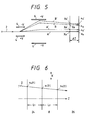
- Fig. 5 shows an example of the ion beam paths both in the case where large and small voltage amplitudes are utilized.
- paths A, A', B and B' are created when voltages +V A , +V A ', +V B and +V B ' are respectively applied to one of the scanning electrodes 4 and a scanning electrode 6 opposite to it, and when voltages -V A , -V A ', -V B and -V B ' are respectfully applied to the other of the scanning electrodes 4 and the scanning electrode 6 located opposite to the other scanning electrode 4.
- This phenomenon occurs because when large amplitudes are used to create beam paths B and B', the ion beam 2, as it passes between the downstream scanning electrodes 6, travels closer to the electrode having the higher potential (positive), and therefore is decelerated and bent back by an increased degree.
- the scanning waveform controlling the ion beam 2 must be shaped in such a way that its scanning speed is increased in the large amplitude region.
- the method of shaping a scanning waveform in the embodiment of the present invention under discussion can be implemented with the same circuit configuration as that shown in Figs. 1 and 2.
- data acquisitioning and other steps for shaping the scanning waveform can be performed when the target 8 or the holder 10 is not in the ion implantation position (i.e., when the target 8 or holder 10 is positioned such that the ion beam 2 is admitted into the downstream multipoint beam monitor 26).
- the scanning waveform controlling an ion beam and therefore the form or profile of the ion beam, can be shaped by the following procedure:
- the above-described method of the present invention determines the speed of scanning of ion beam 2 over the target 8 by utilizing calculations.
- the ion beam 2 of the present invention travels straight except when it passes between scanning electrodes, so that the speed of the scanning of the ion beam of the target 8 can be determined in a way which is correct.
- the difference between the target 8 and each of the multipoint beam monitors 24 and 26 can be ignored, and the scanning waveform that permits the ion beam 2 to be scanned over the target 8 at a constant speed (i.e., such that a uniform dose of ion is implanted into the target 8 in the beam scanning direction) can be constructed in a way which is correct.
- multipoint beam monitors 24 and 26 need not be movable and hence can be designed to operate using a simple mechanism.
- the beam current I of ion beam 2 can be sampled by performing only two scanning cycles, one for each of the upstream and downstream multipoint monitors 24 and 26, respectively. Accordingly, compared to the prior art method involving simulated calculations for potential distribution, the method of the present invention permits the scanning waveform to be shaped rapidly.
- the method according to the embodiment under consideration shapes the scanning waveform and includes compensation for the nonlinearity of high-voltage amplifiers 222 and 223 in the scanning power source 22.
- the scanning waveform can be shaped in a correct way without being influenced by the variations in the characteristics of nonlinear devices such as high-voltage amplifiers 222 and 223.
- the two multipoint beam monitors 24 and 26 are positioned in such a way that the target 8 is placed between them.
- this is not the sole case for the arrangement of these multipoint beam monitors.
- monitor 24 is placed in an upstream location of ion beam 2 and monitor 26 is positioned at a downstream location of ion beam 2 are envisioned.
- either one of the multipoint beam monitors 24 and 26, or both of these monitors may be offset either upward or downward (in the Y-direction) from the beam path of the ion beam implanted into the target 8. This will not cause any inconvenience in measuring the time-dependent change in the scanning position of ion beam 2 as it is being scanned in the X-direction.
- the scanning power source 22 may comprise two variable waveform generators 221 and 224 that generate opposite polarity scanning signals +VS and -VS in response to scanning waveform data DS 1 and DS 2 , respectively, from the control unit 30.
- the scanning power source may also comprise two high-voltage amplifiers 222 and 225 that boost the scanning signals +VS and -VS to output opposite polarity scanning voltages +V and -V, respectively.
- scanning waveform data DS 1 and DS 2 that have been computed in the same way as already described above are supplied from the control unit 30 into the variable waveform generators 221 and 224. In this way, the waveforms of scanning voltages to be supplied to the scanning electrodes 4 and 6 can be varied independently of each other on the +V and -V sides, whereby the desired compensation can be achieved through even finer adjustments.
- the concept of the present invention is applicable not only to the case described above where ion beam 2 performs collimated scanning electrostatically controlled, but also to other cases of scanning such as where electrostatic scanning is combined with deflections by a magnetic field.
- X-direction and "Y-Direction” are merely used to designate two directions that are crossed at right angles. Therefore, the X-direction may be regarded as a horizontal or vertical direction or even as a direction inclined therefrom.
- the collimation of an ion beam and its profile in the beam scanning direction can be measured quantitatively and with high precision without relying upon the experience or hunches made by the operator.
- abnormal collimation of the ion beam that has occurred because of various causes can be detected in a simple and reliable way.
- the collimation of the ion beam can be measured with a simple construction and without taking unduly long time.
- the speed of scanning of the ion beam over the target is determined by calculations so that a scanning waveform that permits the ion beam to be scanned over the target at a constant speed (i.e., that permits a uniform does of ions to be implanted into the target in the beam scanning direction) can be constructed in a way which is correct. Furthermore, at least two cycles of scanning, one for a position downstream of the ion beam and one for a position upstream thereof, will suffice for a measurement of the ion beam.
- the method of the present invention permits the scanning waveform controlling the ion beam to be shaped rapidly.
- Another advantage of the present invention is that the method of the present invention shapes the scanning waveform controlling the ion beam and includes compensation for the nonlinearity of the scanning power source so that the scanning waveform can be shaped in a way which is correct without being influenced by variations in the characteristics of the scanning power source.
- the intended waveform shaping can be accomplished with a simple construction and without taking an unduly long time.
- the ion implanter according to a third aspect of the present invention has two multipoint beam monitors of this type located upstream and downstream of the ion beam, respectively, so that by using such an ion implanter the above-described methods for measuring the collimation of the ion beam and for shaping its form can be implemented in a way which is simple and correct.
Description
- The present invention relates to a method of measuring collimation of an ion beam and of shaping a form of an ion beam scanning wave according to
claims 1 and 3 and to an ion implanter according toclaim 6 and particularly to methods and apparatus yielding electrostatically-controlled collimated scanning of a targer using an ion beam in order to implant ions in the target. - Such a method and apparatus is already disclosed in document EP-A-0 344 918 which describes an ion implanter system. This system comprises a scan controller, a scan amplifier, and scan plates, as well as a beam monitoring apparatus in a target chamber that is located behind the target.
- Document US-A-4 494 005 discloses an ion implanter system, wherein ion beam detectors are arranged in front of a substrate that is provided on a rotary disk.
- Document US-A-4 724 324 discloses an ion implanter apparatus that has an array of Faraday current sensors positioned along a line in the path of the beam so that each sensor intercepts a component of the beam.
- A prior art ion implanter is shown in art in Fig. 11. In this ion implanter, ions extracted from an ion source (not shown in Fig. 11), are optionally analyzed by a magnetic field according to isotopic mass, accelerated to a desired energy level, and refocused at a soot in order to form an
ion beam 2. Theion beam 2 is then deflected for electrostatically-controlled collimated scanning in an X-direction (e.g., horizontal direction X in Fig. 11) by the cooperation of two pairs ofscanning electrodes scanning power source 12. Thereafter, the deflectedion beam 2 illuminates a target 8 (e.g., a wafer) on aholder 10. In the prior art ion implanter of Fig. 11, thescanning power source 12 produces scanning voltages of +V and -V which each have a triangular waveform and which are out of phase by 180°. - The
target 8 is mechanically scanned in a Y-direction (e.g., vertical direction Y in Fig. 11) which is substantially perpendicular to the X-direction by mechanically altering the position of theholder 10 and thetarget 8 through the use of, for example, a holder drive unit (not shown in Fig. 11). This mechanical scanning in the Y-direction, when coupled with the electrostatically-controlled collimated scanning in the X-direction achieved through the deflection ofion beam 2 by scanningelectrode pairs target 8. - In the prior art ion implanter of Fig. 11, a
beam monitor 14 receives theion beam 2 in order to measure a beam current I. Thebeam monitor 14 is provided at one end of a region where theion beam 2 is scanned in the X-direction. The measured beam current I is fed to the Y-axis of adisplay 15 and a scanning voltage (e.g., +V) is fed to the X-axis of the display so that the status of scanning performed by using theion beam 2 is monitored during the ion implantation process. A waveform of the beam current I of scanningion beam 2 is shown in Fig. 12. - In the prior art ion implanter described above, abnormal collimation of the
ion beam 2 can occur for various reasons. Such reasons include the failure or deterioration of thescanning power source 12, the breakage or deterioration of the lead wires (not shown in Fig. 11) connecting thescanning power source 12 to thescanning electrodes ion beam 2 occurs (i.e., if theion beam 2 is not well collimated), the scanning speed of theion beam 2 or the angle of its incidence on thetarget 8 fluctuates, thereby causing various problems such as lower uniformity in the ion implantation oftarget 8. - To detect and thereafter correct the problems caused by the abnormal collimation of
ion beam 2, the operator of the prior art ion implanter must check for abnormal collimation of the ion beam based on the display of the waveform such as shown in Fig. 12. However, many years of experience are required to correctly interpret such a waveform display. Even if the operator is well experienced, for a variety of reasons, it is difficult for the operator to determine whether the collimation of the ion beam is abnormal by observing the waveform display. Such reasons include, but are not limited to, the following: (1) long-term variations in the collimation ofion beam 2 are difficult for the operator to locate; (2) even when thedownstream scanning electrode 6 becomes completely ineffective, a waveform of beam current I, except for a slight shift in peak position, is identical to the one obtained under normal conditions; (3) depending on the ion species, the beam dose, the ion source and other factors, the waveform of beam current I may normally undergo variations or changes similar to those which occur as a result of abnormal collimation; and (4) even if abnormal collimation occurs, a waveform similar to the waveform for normal collimation is still sometimes obtained when the offset voltage of thescanning power source 12 is changed so as to shift the center of the beam scanning. - The scanning waveform controlling an ion beam conventionally has been shaped in accordance with either of the following two major techniques or methods:
- (A) Using a multipoint beam monitor provided in the line of
ion beam 2 or a single beam monitor which is movable in the scanning direction of theion beam 2, the beam current is measured at several points along the scanning direction of theion beam 2 and the scanning waveform controlling theion beam 2 is shaped based on measured values of the beam current; or - (B) A scanning waveform of interest is generated using simulated calculations for distribution of potentials on the beam line of the
ion beam 2. - However, methods (A) and (B) have the following problems. In method (A), if the beam monitor is not located in the same position as the target, the difference between the two positions (i.e., ΔZ) causes the following inequality, with reference to Fig. 5, to result:

- This inequality introduces measurement inaccuracies and makes it impossible to create a desired waveform in a sufficiently correct way in order to achieve a speed of scanning over the target which is constant. Therefore, in order to avoid this problem, the beam monitor must be correctly positioned so that it is located in the same position as the target. As a result, a moving mechanism must be provided so that the beam monitor can be moved to a nonobtrusive position during ion implantation into the target. However, this increases the complexity of the shaping system.
- Method (B) is disadvantageous in that it involves the construction of a complicated simulation model. Furthermore, it is particularly difficult to evaluate the effects of the edges of the scanning electrodes because such an evaluation requires considerable time to perform correct calculations. Moreover, even if data of preferred scanning waveforms are input into the scanning power source (e.g.,
arbitrary waveform generator 221 in the power source 22) in accordance with method (B), undesired factors such as the nonlinearity ofhigh voltage amplifiers power source 22 to produce an output scanning voltage which does not necessarily agree with the input scanning waveform data and which can vary from one measuring apparatus to another, thereby making it difficult to correctly achieve the shaping of scanning waveforms. - The present invention has been made in view of the above circumstances and has as an object to provide a method by which the abnormal collimation of an ion beam can be detected in a simple but reliable way.
- A further object of the present invention is to provide a method by which not only the abnormal collimation of the ion beam is detected, but also shapes the form, or profile, of that ion beam and controls its scanning in such a way that the speed of the scanning of the ion beam over a target approaches or will become a constant value.
- Yet another object of the present invention is to provide an ion implanter which is capable of implementing the methods described above.
- Additional objects and advantages of the invention will be set forth in part in the description which follows and in part will be obvious from the description, or may be learned by practice of the invention. The features and advantages of the invention may be realized and attained by means of the instrumentalities and combinations particularly pointed out in the appended claims.
- These objects are met by the characterizing features of
claims - The accompanying drawings, which are incorporated in and constitute a part of the specification, illustrate embodiments of the invention, and, together with the description, serve to explain the features, advantages and principals of the invention. In the drawings,
- Fig. 1 is a partially schematic diagram and partially pictorial plan view showing in part an ion implanter according to an embodiment of the present invention;
- Fig. 2 is a partially schematic diagram and partially pictorial side elevation of the scanning electrodes and associated components of the system shown in Fig. 1;
- Fig. 3A shows an example of the current waveform of an ion beam measured with a multipoint beam monitor;
- Fig. 3B is a graph showing an example of a scanning position versus time profile of an ion beam which was obtained based on the current waveform shown in Fig. 3A;
- Fig. 4 is a diagram showing an example of the relationship between scanning positions of an ion beam on a multipoint beam monitor located at an upstream location of the ion beam and on a multipoint beam monitor located at a downstream location of the ion beam;
- Fig. 5 is a diagram showing an example of ion beam paths for both large and small scanning electrode voltage amplitudes;
- Fig. 6 is a diagram showing an example of a scanning position of an ion beam on a target as it relates to a scanning position of the ion beam on each of a multipoint monitor located at an upstream location of the ion beam, a multipoint beam monitor located at a downstream location of the ion beam and an intermediate target;
- Fig. 7 is a graph showing an example of a time-dependent change in a scanning position of an ion beam;
- Fig. 8 is a graph showing an example of a time-dependent change in a scanning signal;
- Fig. 9 is a graph showing an example of a relationship between a scanning signal and a scanning position of an ion beam;
- Fig. 10 is a block diagram showing a modified configuration of the scanning power source used in the ion implanter of Fig. 1.
- Fig. 11 is a schematic diagram showing in part an example of a prior art ion implanter; and
- Fig. 12 is a diagram showing a waveform of a beam current during ion implantation.
- Fig. 1 is a schematic diagram showing an ion implanter according to an embodiment of the present invention. As in the prior art ion implanter shown in Fig. 11, ions extracted from an ion source (not shown in Fig. 1) are optionally analyzed by a magnetic field according to isotope mass, accelerated to a desired energy level, and refocused at a spot in order to form
ion beam 2. Theion beam 2 is then deflected for electrostatic parallel scanning in an X-direction (e.g., horizontal direction X in Fig. 1) by the cooperation of a pair ofupstream scanning electrodes 4 and a pair ofdownstream scanning electrode 6 which are supplied with 180° out-of-phase scanning voltages from ascanning power source 22. Thereafter, the deflectedion beam 2illuminates target 8 on aholder 10. - In the ion implanter shown in Fig. 1, a pair of deflecting
electrodes 5 is provided between the upstream pair ofscanning electrodes 4 and the downstream pair ofscanning electrode 6. Theelectrodes 5 deflect theion beam 2 in a Y-direction (e.g., vertical direction Y in Fig. 1 and in Fig. 2) by a predetermined angle (best seen in Fig. 2) so that a neutral beam travelling in a straight path out of the upstream pair ofscanning electrodes 4 is separated to permit only the desiredion beam 2 to strike thetarget 8. The deflectingelectrodes 5 are also used to permit theion beam 2 to be fed into a multipoint beam monitor 24 (described below) by changing (i.e., lowering) the voltage applied to these electrodes. In the system shown in Fig. 1, thetarget 8 is mechanically scanned in the Y-direction (e.g., vertical direction Y in Fig. 1) which is substantially perpendicular to the X-direction by mechanically altering the position of theholder 10 and thetarget 8 through the rocking of anarm 18 which supports theholder 10. While in Fig. 1, thearm 18 is rocked in the direction of arrow R by a reversing motor (e.g., a direct drive motor) 16 so that theholder 10 and thetarget 8 will move in the Y-direction, this is not the only way to move theholder 10 and thetarget 8 in the Y-direction. - Referring again to Fig. 1, two multipoint beam monitors 24 and 26 are positioned, respectively, at an upstream location of the ion beam and at a downstream location of the ion beam such that the
monitor 24 is located upstream of thetarget 8 and theother monitor 26 is located downstream of thetarget 8. Furthermore, theupstream monitor 24 is offset slightly upward so that it will not block the incidence of theion beam 2 on thetarget 8, whereas thedownstream monitor 26 is located predominantly behind thetarget 8, as shown in Fig. 2. - The multipoint beam monitors 24 and 26 each include a plurality of beam detecting points for electrically detecting the
ion beam 2. The beam detecting points are positioned on each multipoint beam monitor so that each monitor has the same set of detecting point coordinate values in the X-direction in which theion beam 2 is scanned and the positions of such beam detecting points are predetermined. The multipoint beam monitors 24 and 26 may each be an array of beam current meters (e.g., Faraday cups) which receive theion beam 2 to measure the beam current I and which are aligned in the X-direction in which theion beam 2 is scanned. Alternatively, a mask having a plurality of holes arranged in the X-direction may be provided in front of a single beam current meter having a longitudinal axis parallel to the X-direction in order to form each of the multipoint beam monitors. - Whichever arrangement is adopted, each of the multipoint beam monitors 24 and 26 is intended to detect a peak of the ion beam current I (as will be described below) so that particularly high precision of measurement is not required for determining the absolute value of beam current I. In other words, variations in factors such as the amount of detection and sensitivity between different beam current detecting points in each of the beam monitors 24 and 26 will not be serious problems to consider.
- The values of the beam current I measured with the multipoint beam monitors 24 and 26 are collected and recorded with a
data logger 28. In the embodiment under consideration, thedata logger 28 is connected to acontrol unit 30 that performs mathematical and other operations to be described below on the basis of the data collected by thedata logger 28. - Furthermore, in the embodiment under consideration, the
scanning power source 22 for supplying scanning voltages +V and -V to thescanning electrodes scanning power source 22 includes avariable waveform generator 221 having a wide range of variation which, in response to applied scanning waveform data (e.g., scanning waveform data DS supplied from the control unit 30), generates a scanning signal VS having a waveform corresponding to the scanning waveform data. Thescanning power source 22 also includes a high-voltage amplifier 222 that boosts the scanning signal VS to output a scanning voltage +V, and a high-voltage amplifier 223 that boosts the scanning signal VS to output a scanning voltage -V having a polarity opposite to +V. - The
variable waveform generator 221 may be of a known type that is capable of generating signals of a variable waveform in accordance with a preset program or in response to applied scanning waveform data. Furthermore, thevariable waveform generator 221 supplies thedata logger 28 with a sync signal (e.g., a clock signal) SY that synchronizes data collection performed by the upstream multipoint beam monitor 24 with data collection performed by the downstreammultipoint beam monitor 26. - The method of measuring the collimation of
ion beam 2 in the ion implanter having the construction described above will now be described. In the embodiment under consideration, the collimation ofion beam 2 can be measured at any time when thetarget 8 or theholder 10 is not in the ion implantation position (i.e., when theion beam 2 is admitted into all detecting points of the downstream multipoint beam monitor 26), such as when thetarget 8 is being transported or when thetarget 8 into which ions are being implanted is moved to a limit of its positions in the Y-direction, as, for example, when it changes its direction of movement from an upward to a downward direction (or vice versa). - The steps of the method of measuring the collimation of
ion beam 2 are as follows: - (1) The method starts with continuously changing the voltage applied to the deflecting
electrodes 5 so that theion beam 2 is admitted into the upstream multipoint beam monitor 24 and the downstream multipoint beam monitor 26 and scans each of the surfaces of these monitors through at least one cycle (i.e., from left to right and vice versa). In order to achieve corrective measurements, these scanning operations are preferably performed under the same conditions, with respect to other inputs, as are used to implant ions into thetarget 8. - (2) In step (1),
data logger 28, in response to the sync signal (i.e., clock signal) SY from thearbitrary waveform generator 221, samples the beam current I ofion beam 2 from both multipoint beam monitors 24 and 26 in synchronism with the operation of thearbitrary waveform generator 221 for successive one-frame periods. - (3) By this sampling, data representing the relationship between (a) time t, where t equals the number of clock periods in a frame multiplied by the duration of one clock period and is counted in clock periods of the sync signal SY from the
arbitrary waveform generator 221, and (b) beam current I is obtained for each of the upstream multipoint beam monitor 24 and the downstreammultipoint beam monitor 26. An example of the data obtained for one of the upstream multipoint monitors is represented in Fig. 3A as a data curve. Both the upstream multipoint beam monitor and the downstream multipoint beam monitor have such a data curve obtained therefor. The data curve of Fig. 3A has a plurality of peaks that each correspond to the state wherein theion beam 2 is incident the center of a respective beam detecting point on the beam monitor for which the data curve is obtained. It should be noted that Fig. 3A refers to the case where the multipoint beam monitor for which the data curve is obtained is composed of a perforated mask located in front of a single beam current meter.
In Fig. 3A, the times t1, t2 ... are associated with positions of the respective peaks and can be determined from the number of clocks provided by the sync signal SY.
The positions of the individual beam detecting points in both multipoint beam monitor 24 and multipoint beam monitor 26 are predetermined. For example, as shown in Fig. 1, the positions of beam detecting points a and b inmultipoint monitor 24 are expressed as -xa and -xb, respectively. - (4) The obtained data representing a discrete relationship between time and position is processed by appropriate interpolation and extrapolation, so that as shown in Fig. 3B, a function that represents the continuous time-dependent change of the scanning position x of
ion beam 2 is determined for the upstreammultipoint beam monitor 24. In the same manner, a function such that shown in Fig. 3B is determined for the downstreammultipoint beam monitor 26. If the collimation of theion beam 2 is consistent for the whole scanning range, the function will assume an ideal triangle waveform as shown in Fig. 3B. However, if it is not, the function will assume a distorted triangular waveform. - (5) Using the two functions (i.e., one for the upstream multipoint beam monitor 24 and the other for the downstream multipoint beam monitor 26), the position xu(t) at which the
ion beam 2 scans the upstream multipoint beam monitor 24 at time t and the position xd(t) at which theion beam 2 scans the downstream multipoint beam monitor 26 at the corresponding time t are determined. Thereafter, the degree of collimation ofion beam 2 at time t is determined based on the relationship between the two positions xu(t) and xd(t). - Assuming that the two multipoint beam monitors 24 and 26 are spaced apart by distance L, if the direction perpendicular to the X-direction in which the
ion beam 2 is scanned is written as Z (see Fig. 4) and if the angle θ theion beam 2 makes with the Z-direction is defined as the degree of its collimation, then the degree of collimation θ(t) at time t can be quantitatively determined by the following equation:
- If the
ion beam 2 at a given time is completely parallel with respect to the Z-direction, then θ = 0°. By altering the time t of interest, the collimation ofion beam 2 at a plurality of points within the scanning range, namely, the distribution of the degrees of collimation, can be determined with a high resolution. - In place of determining θ(t), either xu(t) - xd(t) or xu(t)/xd(t) may be calculated for conveniently determining the collimation of
ion beam 2. - By the foregoing method, the measurement of the collimation of the ion beam can be completed.
- In the embodiment under consideration, the above-described method or procedure for determining the collimation of
ion beam 2 based on the data of beam current I collected by thedata logger 28 was assumed to be performed with acontrol unit 30. However, if desired, this method may be performed by the operator. - According to the foregoing method, the collimation of
ion beam 2 and its profile and the beam scanning direction can be determined quantitatively and with high precision without relying upon the experience or hunches of the operator. Hence, abnormal collimation of theion beam 2 that may occur because of one or more of the causes described in connection with the prior art can be detected in a simple and reliable way. - One of the conventional methods for measuring the collimation of
ion beam 2 includes the steps of passing an ion beam through each of the holes in a perforated mask placed in front of chart paper and examining the relationship between holes and the positions of resulting scorches found on the chart paper. This method, however, has a problem in that it is very cumbersome and time-consuming. For example, each time the measurement is to be conducted, the perforated mask and the chart paper must be brought into the vacuum chamber enclosing the ion implanter after destroying the vacuum in that chamber. - The aforementioned problem is entirely absent from the method of the present invention because the method of the present invention detects the
ion beam 2 electrically using multipoint beam monitors 24 and 26. As a result, there is no need to destroy the vacuum in the vacuum chamber and the collimation ofion beam 2 can be measured as required in a simple way and with the vacuum chamber left in tact. - For electrical detection of the
ion beam 2, it is not absolutely necessary to use the two multipoint beam monitors 24 and 26 utilized in the embodiment described above. For example, if desired, a single multipoint beam monitor that slides in the Z-direction may be used in place of the two multipoint beam monitors 24 and 26. Alternatively, a single beam current meter that slides in the X-direction, or further in the Z-direction, may be used. However, the use of the two multipoint beam monitors 24 and 26 has the advantage of eliminating the need for a moving mechanism which would be necessary to slide a single multipoint beam monitor or beam current meter. Therefore, when the two multipoint beam monitors are used, the collimation of theion beam 2 can be measured with a simple construction without requiring an unduly long time. The advantage of using the two multipoint beam monitors 24 and 26 also applies in the method of shaping the scanning waveform of the ion beam which is to be described in detail below. - As has been described, the ion implanter of the present invention is capable of measuring the collimation of the
ion beam 2. If necessary, this ion implanter may be adapted to shape the waveform of the scanning electrode voltages in order to attain a constant scanning speed and a predetermined profile, or cross-sectional shape, of the ion beam. - Fig. 5 shows an example of the ion beam paths both in the case where large and small voltage amplitudes are utilized. In Fig. 5, paths A, A', B and B' are created when voltages +VA, +VA', +VB and +VB' are respectively applied to one of the
scanning electrodes 4 and ascanning electrode 6 opposite to it, and when voltages -VA, -VA', -VB and -VB' are respectfully applied to the other of thescanning electrodes 4 and thescanning electrode 6 located opposite to theother scanning electrode 4. When VA' - VA = VB' - VB, the 4 points of incidence xA, xA', xB and xB' on the targets satisfy the relationship xA' - xA > xB' - xB. In other words, theion beam 2 tends to converge toward the center of the target. Thus, when beam scanning is performed with a triangular wave (dv/dt = constant), the speed of scanning over the target will increase in the small-amplitude region and decrease in the large-amplitude region. As a consequence, the dose of ion implantation into the target increases towards the periphery of the target. This phenomenon occurs because when large amplitudes are used to create beam paths B and B', theion beam 2, as it passes between thedownstream scanning electrodes 6, travels closer to the electrode having the higher potential (positive), and therefore is decelerated and bent back by an increased degree. - In order to compensate for this unevenness in the dose of ion implantation, the scanning waveform controlling the
ion beam 2 must be shaped in such a way that its scanning speed is increased in the large amplitude region. - All of the above problems encountered in connection with conventional methods (A) and (B), described hereinbefore, can be obviated by shaping the scanning waveform in accordance with the following method of the present invention.
- The method of shaping a scanning waveform in the embodiment of the present invention under discussion can be implemented with the same circuit configuration as that shown in Figs. 1 and 2. As in the case of the collimation measurement, data acquisitioning and other steps for shaping the scanning waveform can be performed when the
target 8 or theholder 10 is not in the ion implantation position (i.e., when thetarget 8 orholder 10 is positioned such that theion beam 2 is admitted into the downstream multipoint beam monitor 26). - In accordance with the present invention, the scanning waveform controlling an ion beam, and therefore the form or profile of the ion beam, can be shaped by the following procedure:
- (1) First of all, steps (1)-(4) which were described in connection with the measurement of the collimation of
ion beam 2 are repeated to determine the scanning positions ofion beam 2 at each of the upstream and downstream multipoint beam monitors 24 and 26 as a function of continuous time. - (2) Then, based on the position of
target 8 relative to the two multipoint beam monitors 24 and 26, as well as the continuous time functions formonitors ion beam 2 on thetarget 8 at time t is determined.
Stated more specifically, with reference to Fig. 6, if the distance between thetarget 8 and the multipoint beam monitor 24 is L1 and the distance between thetarget 8 and the multipoint beam monitor 26 is L2, then the scanning position of theion beam 2 on thetarget 8 at time t (i.e., the scanning position xt(t)) can be determined in accordance with the following equation:
ion beam 2 onmultipoint monitor 24, and xd(t) is the scanning position of theion beam 2 onmultipoint beam monitor 26.
Two examples of the time-dependent change in the scanning position xt(t) ontarget 8 as determined by equation (2) above are depicted in Fig. 7. If the speed of scanning of theion beam 2 over thetarget 8 is constant, the plot of the time-dependent change in scanning position xt(t) is a straight line as indicated by the dashed line C in Fig. 7. If, however, the scanning speed is slow at the periphery of target 8 (e.g., in the case where the ion beam tends to converge toward the center of thetarget 8 such as shown in Fig. 5), the plot is nonlinear as indicated by solid line D in Fig. 7. - (3) If the speed of scanning over the
target 8 is found to be constant in step (2), there is no need to shape the scanning waveform ofion beam 2 and the shaping process ends at this point. - (4) If the speed of scanning over the
target 8 is not constant, both the data of the scanning signal VS produced byarbitrary waveform generator 221 during the sampling of the beam current I of ion beam 2 (e.g., the waveform indicated by the solid line E in Fig. 8, which is already known), and the function described above with reference to Fig. 7 are used to determine a correspondence between the scanning signal VS and the scanning position xt(t) of theion beam 2 ontarget 8. As a consequence, a function having a shape such as shown in Fig. 9 can be obtained. This function can be utilized to predict what value of the scanning signal VS should be produced by thearbitrary waveform generator 221 in thescanning power source 22 in order to cause theion beam 2 to strike thetarget 8 at a desired position. - (5) Based on the function shown in Fig. 9, or a function of this type, the waveform of the scanning signal VS is shaped in such a way that the plot of xt(t) in Fig. 7 becomes straight as represented by dashed line C. In the present case under consideration, this may be accomplished by slightly raising the area around the peak of the scanning signal VS in a manner consistent with dashed line F of Fig. 8. With reference to Fig. 1, in the specific embodiment under discussion, the scanning waveform DS is reconstructed in the
control unit 30 after the waveform of the scanning signal VS is shaped in order to produce new data of that corresponds to the scanning signal VS so shaped. The reconstructed scanning waveform data DS is then supplied to thearbitrary waveform generator 221. - (6) At this point, the method returns to step (1) and the foregoing procedure is repeated until a required constant scanning speed is obtained at target 8 (i.e., until the curve indicated by solid line D in Fig. 7 is reshaped into a desired straight line such as broken line C).
- Unlike the prior art method which measures the scanning speed on a beam monitor, the above-described method of the present invention determines the speed of scanning of
ion beam 2 over thetarget 8 by utilizing calculations. In addition, theion beam 2 of the present invention travels straight except when it passes between scanning electrodes, so that the speed of the scanning of the ion beam of thetarget 8 can be determined in a way which is correct. As a result, the difference between thetarget 8 and each of the multipoint beam monitors 24 and 26 can be ignored, and the scanning waveform that permits theion beam 2 to be scanned over thetarget 8 at a constant speed (i.e., such that a uniform dose of ion is implanted into thetarget 8 in the beam scanning direction) can be constructed in a way which is correct. - Furthermore, the multipoint beam monitors 24 and 26 need not be movable and hence can be designed to operate using a simple mechanism.
- Unless there is a another abnormalcy in the system, the beam current I of
ion beam 2 can be sampled by performing only two scanning cycles, one for each of the upstream and downstream multipoint monitors 24 and 26, respectively. Accordingly, compared to the prior art method involving simulated calculations for potential distribution, the method of the present invention permits the scanning waveform to be shaped rapidly. - As an additional advantage, the method according to the embodiment under consideration shapes the scanning waveform and includes compensation for the nonlinearity of high-
voltage amplifiers scanning power source 22. As a result, the scanning waveform can be shaped in a correct way without being influenced by the variations in the characteristics of nonlinear devices such as high-voltage amplifiers - In the foregoing description, it is assumed that the two multipoint beam monitors 24 and 26 are positioned in such a way that the
target 8 is placed between them. However, this is not the sole case for the arrangement of these multipoint beam monitors. For example, various other situations in which monitor 24 is placed in an upstream location ofion beam 2 and monitor 26 is positioned at a downstream location ofion beam 2 are envisioned. - If desired, either one of the multipoint beam monitors 24 and 26, or both of these monitors, may be offset either upward or downward (in the Y-direction) from the beam path of the ion beam implanted into the
target 8. This will not cause any inconvenience in measuring the time-dependent change in the scanning position ofion beam 2 as it is being scanned in the X-direction. - Another modification that can be made concerns the
scanning power source 22. As shown in Fig. 10, thescanning power source 22 may comprise twovariable waveform generators control unit 30. The scanning power source may also comprise two high-voltage amplifiers control unit 30 into thevariable waveform generators scanning electrodes - The concept of the present invention is applicable not only to the case described above where
ion beam 2 performs collimated scanning electrostatically controlled, but also to other cases of scanning such as where electrostatic scanning is combined with deflections by a magnetic field. - It should also be noted that the terms "X-direction" and "Y-Direction" are merely used to designate two directions that are crossed at right angles. Therefore, the X-direction may be regarded as a horizontal or vertical direction or even as a direction inclined therefrom.
- As described above, according to a first aspect of the present invention, the collimation of an ion beam and its profile in the beam scanning direction can be measured quantitatively and with high precision without relying upon the experience or hunches made by the operator. As a result, abnormal collimation of the ion beam that has occurred because of various causes can be detected in a simple and reliable way.
- Furthermore, there is no need to destroy the vacuum in the vacuum chamber enclosing the ion implanter, and the collimation of the ion beam can be measured as is required in a simple way.
- If two multipoint beam monitors are used for electrical ion beam detection, the collimation of the ion beam can be measured with a simple construction and without taking unduly long time.
- According to the second aspect of the present invention, which provides a method of shaping the form of an ion beam, the speed of scanning of the ion beam over the target is determined by calculations so that a scanning waveform that permits the ion beam to be scanned over the target at a constant speed (i.e., that permits a uniform does of ions to be implanted into the target in the beam scanning direction) can be constructed in a way which is correct. Furthermore, at least two cycles of scanning, one for a position downstream of the ion beam and one for a position upstream thereof, will suffice for a measurement of the ion beam. Therefore, compared to the prior art method involving simulated calculations for potential distribution, the method of the present invention permits the scanning waveform controlling the ion beam to be shaped rapidly. Another advantage of the present invention is that the method of the present invention shapes the scanning waveform controlling the ion beam and includes compensation for the nonlinearity of the scanning power source so that the scanning waveform can be shaped in a way which is correct without being influenced by variations in the characteristics of the scanning power source.
- If two multipoint beam monitors are used for electrical ion beam detection, the intended waveform shaping can be accomplished with a simple construction and without taking an unduly long time.
- The ion implanter according to a third aspect of the present invention has two multipoint beam monitors of this type located upstream and downstream of the ion beam, respectively, so that by using such an ion implanter the above-described methods for measuring the collimation of the ion beam and for shaping its form can be implemented in a way which is simple and correct.
- The foregoing description of the embodiments of the invention has been presented for purposes of illustration and description. It is not intended to be exhaustive or to limit the invention to the precise form disclosed, modifications and variations being possible within the scope of the appended claims. The embodiments were chosen and described in order to explain the principles of the invention and its practical application to enable one skilled in the art to utilize the invention. It is intended that the scope of the invention be defined by the claims appended hereto.
Claims (10)
- A method of measuring collimation of an ion beam (2) used for electrostatically-controlled collimated scanning by electrically detecting the ion beam
characterized by the following steps of:performing an ion beam scan and electrically detecting the time-dependent scanning positions (xu(t);xd(t)) of the ion beam (2) at an upstream location (24) and at a downstream location (26) of the ion beam (2);determining upstream (xu(t)) and downstream (xd(t)) positions of the ion beam (2) at mutually corresponding times; anddetermining the relationship between said respective downstream (xd(t)) and upstream (xu(t)) positions at said respective times (t) and determining the degree of collimation on the basis of the relationship of said respective upstream and downstream positions. - A method according to claim 1, wherein the detecting step comprises electrically detecting the ion beam (2) by a multipoint beam monitor (24) located at the upstream location and a multipoint beam monitor (26) located at the downstream location, the multipoint beam monitors each including a plurality of beam detecting points, positioned so that the coordinate values of both monitors in a scanning direction of the ion beam are equal, whereas the coordinates are predetermined.
- A method of shaping a form of an ion beam scanning wave used for electrostatically-controlled collimated scanning
characterized in thatsaid method comprises the steps of:performing an ion beam scan and electrically detecting the time-dependent scanning positions (xu(t);xd(t)) of the ion beam (2) at an upstream location (24) and at a downstream location (26) of the ion beam (2);determining the time-dependent scanning position (xu(t); xd(t)) of the ion beam on a target (8) on the basis of the relationship between measured positions at the upstream and downstream locations and the position;determining whether the speed of the scanning ion beam over the target (8) is constant; in case the scanning speed of the ion beam (2) is not constant over the target (8), the waveform of a scanning signal (VS) is shaped so that the scanning speed is constant. - A method according to claim 3, wherein the detecting step comprises electrically detecting the ion beam by a multipoint beam monitor (24) located at the upstream location and a multipoint beam monitor (26) located at the downstream location, the multipoint beam monitors (24,26) each including a plurality of beam detecting points, positioned so that the coordinate values of both monitors in a scanning direction of the ion beam are equal, whereas the coordinates are predetermined.
- An ion implanter for performing electrostatically-controlled collimated scanning using an ion beam with a beam monitor
characterized in thatsaid implanter comprises:a multipoint beam monitor (24) located at an upstream location of the ion beam (2) and a multipoint beam monitor (26) located at a downstream location of the ion beam (2), said monitors (24,26) each comprising a plurality of beam detection points positioned so that the coordinate values in the scanning direction of the ion beam of the two monitors are equal, whereas the coordinates are predetermined; anda control system (30) for performing an ion beam scan and electrically detecting the time-dependent scanning positions (xu(t);xd(t)) of the ion beam (2) at said multipoint beam monitor (24) located upstream and at said multipoint beam monitor (26) located downstream of said beam. - An ion implanter according to claim 5, comprising said control system (30) for shaping a form of the ion beam in response to electrical detection of the ion beam by the multipoint monitors.
- An ion beam implanter according to claim 6, wherein said control system (30) comprises a sampling unit for sampling a beam current of the ion beam and a waveform generator (21) for controlling the form of the ion beam and for providing a synchronization signal to the sampling unit.
- An ion beam implanter according to claim 5, wherein said multipoint beam monitors (24,26) each comprises an array of beam current meters.
- An ion beam implanter according to claim 5, wherein said multipoint beam monitors (24,25) each cmoprises a single beam current meter disposed behind a mask having a plurality of apertures.
- An ion beam implanter according to claim 5, wherein said ion implanter detects a scanning position xt(t) of the ion beam at a time t on a target located between the multipoint beam monitors in accordance with the following equation:

Applications Claiming Priority (2)
| Application Number | Priority Date | Filing Date | Title |
|---|---|---|---|
| JP2127230A JP2969788B2 (en) | 1990-05-17 | 1990-05-17 | Ion beam parallelism measurement method, scanning waveform shaping method, and ion implantation apparatus |
| JP127230/90 | 1990-05-17 |
Publications (3)
| Publication Number | Publication Date |
|---|---|
| EP0457321A2 EP0457321A2 (en) | 1991-11-21 |
| EP0457321A3 EP0457321A3 (en) | 1992-03-18 |
| EP0457321B1 true EP0457321B1 (en) | 1997-01-15 |
Family
ID=14954949
Family Applications (1)
| Application Number | Title | Priority Date | Filing Date |
|---|---|---|---|
| EP91107947A Expired - Lifetime EP0457321B1 (en) | 1990-05-17 | 1991-05-16 | Method and apparatus for measuring ion beam collimation, shaping the ion beam and controlling scanning thereof |
Country Status (5)
| Country | Link |
|---|---|
| US (1) | US5180918A (en) |
| EP (1) | EP0457321B1 (en) |
| JP (1) | JP2969788B2 (en) |
| KR (1) | KR940009197B1 (en) |
| DE (1) | DE69124136T2 (en) |
Families Citing this family (36)
| Publication number | Priority date | Publication date | Assignee | Title |
|---|---|---|---|---|
| US5319212A (en) * | 1992-10-07 | 1994-06-07 | Genus, Inc. | Method of monitoring ion beam current in ion implantation apparatus for use in manufacturing semiconductors |
| JP3288554B2 (en) * | 1995-05-29 | 2002-06-04 | 株式会社日立製作所 | Ion implantation apparatus and ion implantation method |
| US6827824B1 (en) | 1996-04-12 | 2004-12-07 | Micron Technology, Inc. | Enhanced collimated deposition |
| US5898179A (en) | 1997-09-10 | 1999-04-27 | Orion Equipment, Inc. | Method and apparatus for controlling a workpiece in a vacuum chamber |
| US6480278B1 (en) * | 1997-12-16 | 2002-11-12 | Stephen Douglas Fuerstenau | Method and apparatus for detection of charge on ions and particles |
| JP3567749B2 (en) * | 1998-07-22 | 2004-09-22 | 日新電機株式会社 | Method for measuring distribution of charged particle beam and related methods |
| JP4207307B2 (en) | 1999-04-26 | 2009-01-14 | 日新イオン機器株式会社 | Charge-up measuring device |
| US6791094B1 (en) | 1999-06-24 | 2004-09-14 | Varian Semiconductor Equipment Associates, Inc. | Method and apparatus for determining beam parallelism and direction |
| GB2355337B (en) * | 1999-10-12 | 2004-04-14 | Applied Materials Inc | Ion implanter and beam stop therefor |
| US6323497B1 (en) * | 2000-06-02 | 2001-11-27 | Varian Semiconductor Equipment Assoc. | Method and apparatus for controlling ion implantation during vacuum fluctuation |
| US6437350B1 (en) * | 2000-08-28 | 2002-08-20 | Varian Semiconductor Equipment Associates, Inc. | Methods and apparatus for adjusting beam parallelism in ion implanters |
| US6573518B1 (en) | 2000-10-30 | 2003-06-03 | Varian Semiconductor Equipment Associates, Inc. | Bi mode ion implantation with non-parallel ion beams |
| WO2002058103A2 (en) | 2001-01-17 | 2002-07-25 | Varian Semiconductor Equipment Associates, Inc. | In situ ion beam incidence angle and beam divergence monitor |
| US7323700B1 (en) | 2001-04-02 | 2008-01-29 | Applied Materials, Inc. | Method and system for controlling beam scanning in an ion implantation device |
| CA2448567C (en) | 2001-05-25 | 2014-05-20 | Duke University | Modulators of nucleic acid ligands |
| JP3692999B2 (en) | 2001-10-26 | 2005-09-07 | 日新イオン機器株式会社 | Ion implantation method and apparatus |
| US6911660B2 (en) * | 2002-10-02 | 2005-06-28 | Varian Semiconductor Equipment Associates, Inc. | Method of measuring ion beam angles |
| US6677598B1 (en) * | 2003-04-29 | 2004-01-13 | Axcelis Technologies, Inc. | Beam uniformity and angular distribution measurement system |
| US7105839B2 (en) * | 2003-10-15 | 2006-09-12 | White Nicholas R | Method and fine-control collimator for accurate collimation and precise parallel alignment of scanned ion beams |
| JP4133883B2 (en) | 2003-12-04 | 2008-08-13 | 日新イオン機器株式会社 | Ion beam equipment |
| JP4251453B2 (en) | 2004-02-23 | 2009-04-08 | 日新イオン機器株式会社 | Ion implantation method |
| JP2006019048A (en) | 2004-06-30 | 2006-01-19 | Toshiba Corp | Manufacturing method of ion implantation device and semiconductor device |
| US6989545B1 (en) * | 2004-07-07 | 2006-01-24 | Axcelis Technologies, Inc. | Device and method for measurement of beam angle and divergence |
| EP1722398B1 (en) * | 2005-05-14 | 2009-11-25 | FEI Company | Deflection Signal Compensation for Charged Particle Beam |
| JP4561690B2 (en) * | 2005-05-24 | 2010-10-13 | 日新イオン機器株式会社 | Ion beam measurement method and ion implantation apparatus |
| US7397049B2 (en) * | 2006-03-22 | 2008-07-08 | Varian Semiconductor Equipment Associates, Inc. | Determining ion beam parallelism using refraction method |
| KR100785725B1 (en) | 2006-05-23 | 2007-12-18 | 닛신 이온기기 가부시기가이샤 | Ion beam measuring method and ion implanting apparatus |
| US7663125B2 (en) * | 2006-06-09 | 2010-02-16 | Varian Semiconductor Equipment Associates, Inc. | Ion beam current uniformity monitor, ion implanter and related method |
| JP4872603B2 (en) * | 2006-10-31 | 2012-02-08 | 日新イオン機器株式会社 | Ion implanter |
| US7547900B2 (en) * | 2006-12-22 | 2009-06-16 | Varian Semiconductor Equipment Associates, Inc. | Techniques for providing a ribbon-shaped gas cluster ion beam |
| JP5103968B2 (en) * | 2007-03-20 | 2012-12-19 | 日新イオン機器株式会社 | Ion beam traveling angle correction method and ion implantation apparatus |
| JP4784544B2 (en) * | 2007-04-03 | 2011-10-05 | 日新イオン機器株式会社 | Method of measuring beam width and divergence angle of ion beam and ion implantation apparatus |
| US8164068B2 (en) * | 2009-07-30 | 2012-04-24 | Varian Semiconductor Equipment Associates, Inc. | Mask health monitor using a faraday probe |
| US8314409B2 (en) | 2009-08-28 | 2012-11-20 | Fei Company | Pattern modification schemes for improved FIB patterning |
| JP5970394B2 (en) * | 2013-02-27 | 2016-08-17 | 株式会社日立ハイテクノロジーズ | Inspection device |
| JP6195538B2 (en) * | 2014-04-25 | 2017-09-13 | 住友重機械イオンテクノロジー株式会社 | Ion implantation method and ion implantation apparatus |
Family Cites Families (12)
| Publication number | Priority date | Publication date | Assignee | Title |
|---|---|---|---|---|
| US4021675A (en) * | 1973-02-20 | 1977-05-03 | Hughes Aircraft Company | System for controlling ion implantation dosage in electronic materials |
| US4011449A (en) * | 1975-11-05 | 1977-03-08 | Ibm Corporation | Apparatus for measuring the beam current of charged particle beam |
| JPS56126918A (en) * | 1980-03-11 | 1981-10-05 | Hitachi Ltd | Injecting device for ion |
| JPS62295347A (en) * | 1986-04-09 | 1987-12-22 | イクリプス・イオン・テクノロジ−・インコ−ポレイテツド | Ion beam fast parallel scanner |
| US4751393A (en) * | 1986-05-16 | 1988-06-14 | Varian Associates, Inc. | Dose measurement and uniformity monitoring system for ion implantation |
| JPS6386340A (en) * | 1986-09-30 | 1988-04-16 | Fujitsu Ltd | Primary particle beam radiation device |
| US4724324A (en) * | 1986-11-24 | 1988-02-09 | Varian Associates, Inc. | Method and apparatus for ion beam centroid location |
| JPS63152844A (en) * | 1986-12-16 | 1988-06-25 | Nec Corp | Ion beam scan control device |
| US4967380A (en) * | 1987-09-16 | 1990-10-30 | Varian Associates, Inc. | Dual channel signal processor using weighted integration of log-ratios and ion beam position sensor utilizing the signal processor |
| US4851693A (en) * | 1988-06-03 | 1989-07-25 | Varian Associates, Inc. | Compensated scan wave form generator for ion implantation equipment |
| JPH077658B2 (en) * | 1989-05-15 | 1995-01-30 | 日新電機株式会社 | Ion implanter |
| JPH0770296B2 (en) * | 1989-05-15 | 1995-07-31 | 日新電機株式会社 | Ion implanter |
-
1990
- 1990-05-17 JP JP2127230A patent/JP2969788B2/en not_active Expired - Fee Related
-
1991
- 1991-05-15 US US07/700,451 patent/US5180918A/en not_active Expired - Lifetime
- 1991-05-16 DE DE69124136T patent/DE69124136T2/en not_active Expired - Fee Related
- 1991-05-16 EP EP91107947A patent/EP0457321B1/en not_active Expired - Lifetime
- 1991-05-17 KR KR1019910008027A patent/KR940009197B1/en not_active IP Right Cessation
Also Published As
| Publication number | Publication date |
|---|---|
| JPH0422900A (en) | 1992-01-27 |
| EP0457321A3 (en) | 1992-03-18 |
| EP0457321A2 (en) | 1991-11-21 |
| JP2969788B2 (en) | 1999-11-02 |
| KR940009197B1 (en) | 1994-10-01 |
| US5180918A (en) | 1993-01-19 |
| DE69124136T2 (en) | 1997-04-24 |
| DE69124136D1 (en) | 1997-02-27 |
| KR910020793A (en) | 1991-12-20 |
Similar Documents
| Publication | Publication Date | Title |
|---|---|---|
| EP0457321B1 (en) | Method and apparatus for measuring ion beam collimation, shaping the ion beam and controlling scanning thereof | |
| EP0398269B1 (en) | Ion implantation apparatus | |
| US6690022B2 (en) | Ion beam incidence angle and beam divergence monitor | |
| US4980562A (en) | Method and apparatus for high efficiency scanning in an ion implanter | |
| US4764970A (en) | Method and apparatus for detecting cracks | |
| US6297510B1 (en) | Ion implant dose control | |
| JP2709594B2 (en) | Ion beam control method and display device used therefor | |
| TW571351B (en) | Method and apparatus for tuning ion implanters | |
| GB1286454A (en) | Surface potential analysis by electron beams | |
| CN104916518A (en) | Ion implanter, beam energy measuring device, and method of measuring beam energy | |
| JPS6010720A (en) | Electron beam controller | |
| JPS5822854B2 (en) | Kadenriyuushisousakenbikiyou | |
| JP3407468B2 (en) | Adjustment method for ion beam parallelization | |
| US20200027698A1 (en) | Apparatus and techniques for beam mapping in ion beam system | |
| JP2870924B2 (en) | Ion beam monitoring method and apparatus | |
| JP3456318B2 (en) | Beam scanning waveform shaping method | |
| JPH04301345A (en) | Parallel scanning method for ion beam | |
| JPH025346A (en) | Ion implanter and adjustment of ion beam | |
| JPH0817196B2 (en) | Electron beam probe device | |
| JP2720651B2 (en) | Ion implanter | |
| JPH0317947A (en) | Ion implanting device | |
| JPH02312152A (en) | Ion implantation device | |
| JPH0586616B2 (en) | ||
| Strehl et al. | Measurements in Phase Spaces | |
| JPS58147949A (en) | Ion implantation device |
Legal Events
| Date | Code | Title | Description |
|---|---|---|---|
| PUAI | Public reference made under article 153(3) epc to a published international application that has entered the european phase |
Free format text: ORIGINAL CODE: 0009012 |
|
| AK | Designated contracting states |
Kind code of ref document: A2 Designated state(s): DE FR GB IT |
|
| PUAL | Search report despatched |
Free format text: ORIGINAL CODE: 0009013 |
|
| AK | Designated contracting states |
Kind code of ref document: A3 Designated state(s): DE FR GB IT |
|
| 17P | Request for examination filed |
Effective date: 19920707 |
|
| 17Q | First examination report despatched |
Effective date: 19940812 |
|
| GRAG | Despatch of communication of intention to grant |
Free format text: ORIGINAL CODE: EPIDOS AGRA |
|
| GRAH | Despatch of communication of intention to grant a patent |
Free format text: ORIGINAL CODE: EPIDOS IGRA |
|
| GRAH | Despatch of communication of intention to grant a patent |
Free format text: ORIGINAL CODE: EPIDOS IGRA |
|
| GRAA | (expected) grant |
Free format text: ORIGINAL CODE: 0009210 |
|
| AK | Designated contracting states |
Kind code of ref document: B1 Designated state(s): DE FR GB IT |
|
| REF | Corresponds to: |
Ref document number: 69124136 Country of ref document: DE Date of ref document: 19970227 |
|
| ITF | It: translation for a ep patent filed |
Owner name: 0508;03RMFSOCIETA' ITALIANA BREVETTI S.P |
|
| ET | Fr: translation filed | ||
| PLBE | No opposition filed within time limit |
Free format text: ORIGINAL CODE: 0009261 |
|
| STAA | Information on the status of an ep patent application or granted ep patent |
Free format text: STATUS: NO OPPOSITION FILED WITHIN TIME LIMIT |
|
| 26N | No opposition filed | ||
| REG | Reference to a national code |
Ref country code: GB Ref legal event code: IF02 |
|
| PGFP | Annual fee paid to national office [announced via postgrant information from national office to epo] |
Ref country code: FR Payment date: 20040510 Year of fee payment: 14 |
|
| PG25 | Lapsed in a contracting state [announced via postgrant information from national office to epo] |
Ref country code: IT Free format text: LAPSE BECAUSE OF NON-PAYMENT OF DUE FEES Effective date: 20050516 |
|
| PG25 | Lapsed in a contracting state [announced via postgrant information from national office to epo] |
Ref country code: FR Free format text: LAPSE BECAUSE OF NON-PAYMENT OF DUE FEES Effective date: 20060131 |
|
| REG | Reference to a national code |
Ref country code: FR Ref legal event code: ST Effective date: 20060131 |
|
| REG | Reference to a national code |
Ref country code: GB Ref legal event code: 732E |
|
| PGFP | Annual fee paid to national office [announced via postgrant information from national office to epo] |
Ref country code: DE Payment date: 20070510 Year of fee payment: 17 |
|
| PGFP | Annual fee paid to national office [announced via postgrant information from national office to epo] |
Ref country code: GB Payment date: 20070516 Year of fee payment: 17 |
|
| GBPC | Gb: european patent ceased through non-payment of renewal fee |
Effective date: 20080516 |
|
| PG25 | Lapsed in a contracting state [announced via postgrant information from national office to epo] |
Ref country code: DE Free format text: LAPSE BECAUSE OF NON-PAYMENT OF DUE FEES Effective date: 20081202 |
|
| PG25 | Lapsed in a contracting state [announced via postgrant information from national office to epo] |
Ref country code: GB Free format text: LAPSE BECAUSE OF NON-PAYMENT OF DUE FEES Effective date: 20080516 |