EP0458650A2 - Method and apparatus for interlaced multicolor printing - Google Patents
Method and apparatus for interlaced multicolor printing Download PDFInfo
- Publication number
- EP0458650A2 EP0458650A2 EP91304735A EP91304735A EP0458650A2 EP 0458650 A2 EP0458650 A2 EP 0458650A2 EP 91304735 A EP91304735 A EP 91304735A EP 91304735 A EP91304735 A EP 91304735A EP 0458650 A2 EP0458650 A2 EP 0458650A2
- Authority
- EP
- European Patent Office
- Prior art keywords
- printing
- color
- lines
- colors
- Prior art date
- Legal status (The legal status is an assumption and is not a legal conclusion. Google has not performed a legal analysis and makes no representation as to the accuracy of the status listed.)
- Withdrawn
Links
Images
Classifications
-
- B—PERFORMING OPERATIONS; TRANSPORTING
- B41—PRINTING; LINING MACHINES; TYPEWRITERS; STAMPS
- B41J—TYPEWRITERS; SELECTIVE PRINTING MECHANISMS, i.e. MECHANISMS PRINTING OTHERWISE THAN FROM A FORME; CORRECTION OF TYPOGRAPHICAL ERRORS
- B41J2/00—Typewriters or selective printing mechanisms characterised by the printing or marking process for which they are designed
- B41J2/005—Typewriters or selective printing mechanisms characterised by the printing or marking process for which they are designed characterised by bringing liquid or particles selectively into contact with a printing material
- B41J2/01—Ink jet
- B41J2/21—Ink jet for multi-colour printing
- B41J2/2132—Print quality control characterised by dot disposition, e.g. for reducing white stripes or banding
Definitions
- This invention relates to color printing wherein a color image is formed by printing repeated sets of lines with different colors by a print head scanning a print medium. It particularly relates to color printing with interlacing of at least two colors, such as two of the three conventional subtractive primary colors, cyan, magenta and yellow.
- the preferred method and embodiment for practicing the present invention is particularly directed to an ink jet printer wherein a print head scans over a print medium, most typically a sheet of paper or transparent film, by shuttling back and forth across the sheet (bi-directional movement) or by moving continuously along the sheet in one direction while the sheet is held against a rotating drum.
- Images are formed by selectively and serially depositing ink drops of primary or base colors at uniformly spaced address locations disposed in uniformly spaced rows to form a dot-matrix image. Variations in color may be achieved by depositing one or more ink drops of more than one size or color at an address to form picture elements or pixels.
- the present invention is equally applicable to any printing process wherein a print head travels along parallel lines relative to a print medium to form a desired final image, whether the image be graphic or textual.
- the term "print” is considered to include the general situation where a print element or nozzle addresses an ink drop location, whether or not ink is deposited.
- the size of the drop may vary and even the number of drops of a given color that are deposited at a particular address can vary.
- Hewlett-Packard Labs has demonstrated the latter with drop-on-demand (DOD) thermal ink jets; and Hertz, at the Lund Institute in Sweden, has also demonstrated this with continuous ink jets. Printing with drops of several selected sizes (for gray scale control at each address) was demonstrated by MRIT with air assisted DOD jets in the early 1980s.
- Print heads are known that contain a nozzle for each color of printing for a single line. These nozzles are positioned adjacent to a sheet of paper. A print head carriage then moves relative to the paper one line at a time depositing ink pixels at selected pixel locations until the entire image area has been scanned.
- ink jets have more than one nozzle to print a given color on each address of a given line.
- One nozzle is used to print ink at its maximum optical density, and the other(s) to print ink at some diluted dye concentration(s) so that more than one optical density level of the color can be obtained at each address.
- Some early printers also had the nozzles aligned normal to the scan direction for scanning spaced-apart parallel lines. Thus, colors are always laid down in the same sequence, and one color has time to dry before the next one is printed on top of it.
- Hirata et al. in U. S. Patent No. 4,554,556 entitled “Color Plotter”, disclose printing a dot with all three colors at once, or sequentially during a single scan.
- Tozaki in U. S. patent No. 4,580,150 entitled “Recording Apparatus”, disclosed a print array in which two nozzles are used to print one color in a limited image region and then a single nozzle is used to print a second color over the same region.
- each color dries before the next color is deposited, and the colors are always deposited in the same sequence.
- all the colors are deposited during each scan and the sequence of deposition is reversed for the two scan directions.
- Line interlacing means that adjacent lines of dots of the same color are printed in sequential scans of the pen. For example, lines 1, 3, 5, etc., might be printed in one scan, while lines 2, 4, 6, etc., would be printed in the next scan. In a high speed printer, it is desirable to print in both scan directions. With line interlacing, any printing errors and hence image defects that might be dependent on the scan direction would be generated at the spatial frequency of the inverse line spacing and should be less noticeable than if they were generated at a lower spatial frequency.
- inks are used in drop-on-demand printing. These are primarily water-based inks, oil-based inks, and hot-melt or thermoplastic inks. The latter inks are preferred, due to the intensity of the colors and the fact that they can be used on many different print mediums.
- a discussion of printing with colored inks, generally, and with hot-melt inks, in particular, is discussed by Howard et al. in U. S. Patent No. 4,741,930 entitled "Ink Jet Color Printing Method".
- dots of hot-melt ink that have not set are deposited continuously together or on top of each other, they mix. When they mix, the resultant color is different than it is if the first dot solidifies before the second dot is deposited.
- the color laydown sequence is also important. Different sequences produce color hue shifts and appearances of surface irregularities.
- each of the multicolor overlay sequences should always be the same regardless of scan direction. If this is not possible, then the next best thing is to have the sequences alternate on adjacent lines so that the spatial frequency of the hue variations will be as high as possible and will be averaged out as much as possible by the visual system of an observer.
- the present invention provides a method and apparatus for substantially reducing color image irregularities while minimizing the number of address lines spanned by the array.
- the preferred embodiment of the present invention is usable in a serial, dot-matrix, print-on-demand ink jet head described in co-pending US Patent Application Serial No 07/419,367, filed October 10, 1989 for "Method and Apparatus for Interlaced Printing", assigned to the same assignee as the present invention (European Patent Application No 90 311119.3).
- This disclosure describes an ink jet printer for printing band and line interlacing with a single color such as would be used for monochromatic graphic or text images. This application is incorporated herein by reference.
- the present application further improves on the above application and on the known prior art by providing improved color imaging.
- the present invention provides a method and apparatus for printing a color image on a print medium along print lines having centers spaced a , predetermined interline distance apart.
- the method generally includes printing first and second colors on alternating lines of a first set of lines, and subsequently printing the first and second colors on a second set of print lines while printing the first color on lines of the first set of colors previously printed with the second color.
- the second color or a third color is also printed on the lines of the first set simultaneously with printing of the first color.
- This color interlacing may be extended to include four interlaced colors printed simultaneously or in various combinations of interlaced sets. Interlacing of two, three and four colors is specifically illustrated in order to achieve various combinations of line and band interlacing and overlay sequences.
- a first color and a second color are printed on a first set of print lines, with the first and second colors being printed on respective alternate print lines.
- the first color and a third color are printed on a second set of print lines, with the first and third colors being printed on respective alternate print lines.
- the second color and the third color are printed on a third set of print lines, with the second and third colors being printed on respective alternate print lines.
- each color must be printed by the same number of jets, N, where N is an even integer.
- This method provides color printing with two of the color pairs alternating by line in order of color overlay, and with a constant order of color overlay for the third color pair.
- Other combinations will be seen to provide various mixes of band and line interlacing of individual colors, and either constant or alternating line overlay sequences.
- the same lines are printed by first and second sets of printing elements.
- Each set of printing elements prints alternating lines of two colors, with the two sets of printing elements printing different colors. Thus, four colors are printed.
- the printing elements are aligned so that yellow and magenta are printed on the same lines and black and cyan on the same lines. There are equal numbers of printing elements printing each color.
- the print medium advances relative to the print head after each pass a distance equal to the interline distance times the number of lines addressed by the printing elements printing a single color.
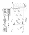
- Fig. 1 is a general block diagram illustrating a printer apparatus for practicing the present invention.
- Fig. 2 is a diagram illustrating an exemplary ink jet head array and representative color print scan of a print medium.
- Figs. 3 and 4 illustrate two-color printing using two configurations of the nozzles in a print-head array like that of Fig. 2 for achieving different overlay sequence combinations.
- Figs. 5 - 10 illustrate three-color printing with different head configurations.
- Fig. 7 illustrates printing using a conventional head configuration.
- Figs. 11 - 13 illustrate four-color printing with different head configurations.
- Printer 10 receives scan data from a data source 12. This data defines the colors to be printed at each pixel location on a predetermined image area of a print medium.
- the data is fed into a printer driver 13 that controls operation of a print engine 14.
- Control includes feeding formatted data to a print head 16, the movement of which is provided by a carriage controlled by a carriage servo 18.
- Control signals are exchanged between the printer driver, the carriage servo, and other mechanical systems, not shown, such as a print medium mover to provide coordinated movement of the print head relative to the print medium during printing.
- a detailed description of a printer 10 usable for practicing this invention, is as described in the previously reference application entitled "Method and Apparatus for Interlaced Printing". That application also describes well known prior art techniques for interlaced printing in a single color.
- Array 20 usable in printer 10 is shown positioned next to a print medium 22, such as a sheet of suitable paper.
- Array 20 includes a first group 24 of individual black-ink-printing nozzles 26, and a second group 28 of color-ink-printing nozzles 30. It will be understood that black, white and various colors of the color spectrum in between are all considered colors.
- Array 20, and associated print head 16 thus prints using a plurality of colors.
- Group 24 comprises sets 32, 33 and 34.
- Group 28 comprises sets 36, 37 and 38.
- Group 24 is positioned vertically (in the direction of the print medium movement) above group 28 so that sets 32 and 38 print on the same lines during a single scan of the array.
- the six sets of nozzles thus print five sets 40, 41, 42, 43 and 44 of lines in a single scan.
- ink colors are represented by a geometric symbol.
- a triangle represents black
- a square, a diamond, and a circle each represent one of three other colors, such as the three conventional subtractive primary colors, magenta, cyan and yellow. Other colors could also be used.
- a column 46 of triangles on print medium 22 indicates the lines addressed and that may be printed by the nozzles in group 24.
- a column 48 of squares, diamonds, and circles indicates the lines addressed by the nozzles in group 28. There is a mix of colors in column 48 that will be more fully discussed with reference to Fig. 3. Between scans the array is shifted downward relative to the print medium, the width D equivalent of four print lines, or the width of one set of print lines.
- the lines of the top two set of black nozzles print alternate lines as illustrated by the arrows associated with the triangle symbols.
- the arrows indicate which nozzles print during scan movement in the direction shown by the arrows.
- the array configuration provides for printing with black ink after the primary colors are printed. This is important where the inks do not dry quickly or where there is bleeding of the colors. By printing black last, a constant sequence of deposition is provided relative to the other colors. Also, when printing only black text, group 28 is disabled and all nozzles in group 24 are used so that printing can take place three times as fast as during color image printing.
- Fig. 2 shows an "ideal" embodiment in that black is always printed on a given line after all of the other colors have been printed. (Note: there is no occasion when black is ever printed at the same address as any of the other colors. Further, there is never an occasion when all of the three subtractive colors are printed at the same address.)
- This "ideal" embodiment extends the nozzle array in the vertical direction more than would be preferred.
- An alternative embodiment, shown in dashed lines in Fig. 2 has the black array 24′ shifted so that there is a black nozzle 26′ on every line there is a color nozzle. This is the most compact embodiment in the vertical direction, and in this sense, is also an "ideal" embodiment.
- array 20 or 20′ is representative.
- the intended commercial embodiment is four times the size of array 20′. That is, there are 48 black-printing nozzles, and 48 multicolor-printing nozzles. Thus, instead of sets of 4 nozzles, there are sets of 16 nozzles. However, the color sequences are the same as those shown, just longer.
- Figs. 3 - 13 illustrate various arrangements that satisfy various ones of the desired features of a color printing system discussed earlier. In these figures, time is considered to progress from left to right. Thus, symbols shown on the same print line are considered to overlay each other, with the sequence of deposition occurring as determined by the deposition timing identified by sequential scans 1 - 3 or 4.
- Figs. 3 and 4 illustrate two configurations for printing two colors with color interlacing.
- Fig. 3 shows two colors represented as circles and diamonds that simply alternate within a set of printing elements for printing line-by-line alternating colors.
- the number N of nozzles must be odd.
- Fig. 3 there are three nozzles of each color and the print head is shifted a distance D equal to the width of three lines between scans.
- the resulting overlay sequence is represented in the outlined region 50. It can be seen that the overlay sequence alternates with every line, except for the band edges.
- This method and configuration provide for band and line interlacing.
- Line interlacing results because each color is printed on only odd numbered lines in one scan and only on even numbered lines in the next scan, since the incremental distance change D is equivalent to the width of an odd number of lines.
- FIG. 4 An alternative two-color printing configuration is shown in Fig. 4.
- the head color array is made up of two sets of four nozzles, with the nozzles alternating colors within each set, but with the placement of colors in each set reversed. For instance, during scan 1, the color represented by a circle prints on lines 1 and 3 in the first set and on lines 6 and 8 in the second set. As can be seen, the color in one set always prints on the odd lines and the same color in the other set always prints on the even lines.
- the overlay sequence alternates every line. Considering that the band of circles encompasses eight lines, and that for diamonds encompasses six lines, the circles have near perfect band interlacing, whereas the diamonds have partial band interlacing. Also, it can be seen that the diamonds are printed on two consecutive lines during each scan. Otherwise line interlacing is also achieved.
- Figs. 5 - 10 show different head configurations for printing three colors, such as the primary subtractive colors, cyan, magenta and yellow.
- Fig. 5 illustrates the case where the three colors alternate within a single set of nozzles.
- N the number of nozzles of each color, must not be an integer multiple of three.
- each line is only addressed once, and the overlay sequence of each color pair does not alternate perfectly line-by-line.
- the order of circle/square, square/diamond and diamond/circle repeats every two out of three lines. However, there is both band and line interlacing of each color.
- Fig. 6 The configuration shown in Fig. 6 is the same as that illustrated in Fig. 2 for the jets that print in color.
- three sets of four nozzles are used, with each set printing alternating lines of two colors. Each set prints a different one of the three pairs of colors: square/circle, diamond/square and circle/diamond.
- lines 9 and 10 are the first lines to be overlaid by all three sets of nozzles.
- the resulting overlay sequence is represented in the outlined region 56.
- the ink drop locations in line 9 are addressed ("printed") first by the nozzle printing the color represented by the circle, followed by the nozzle printing a diamond and then by a nozzle printing a square.
- the circle is printed before both the diamond and the square
- the diamond is printed before the square.
- no more than two colors are printed at a single ink drop address location.
- Printing all three at one address results in "composite” or "three-color” black which always has a noticeable, dingy and repugnant hue. This arises because the subtractive primary colors are not ideal. Thus, it is better to print a single drop of pure black.
- line 10 the diamond is printed before the square and the circle, and the square is printed before the circle. This alternating pattern applies to all of the lines printed, as could be illustrated by continuing to draw columns for scans 4 and beyond.
- the printing method illustrated in Fig. 6, and the print element array associated with it, provide for band interlacing of squares and diamonds, and line interlacing of all three colors.
- the bands of squares and diamonds each span thirty-two lines in this, the intended commercial embodiment.
- This array also provides a constant deposition order for one pair of colors (diamonds and squares), and provides alternative deposition orders for the other two pairs of colors (circles and diamonds, and circles and squares) on adjacent lines.
- each of print head sets 36, 37 and 38 have a single color, as is conventionally known.
- the first set is circles
- the second set is diamonds
- the third set is squares.
- each color is neither band interlaced nor line interlaced.
- Fig. 8 shows yet another embodiment, this one having the first two print element sets 36 and 37 alternating between circles and diamonds, and the third set 38 all squares.
- this embodiment provides both line and band interlacing for two colors (circles and diamonds) and a constant color overlay sequence for two of the color pairs (diamonds and squares, and circles and squares).
- the third color (squares) is neither line nor band interlaced.
- Fig. 9 the set 37 of printing elements printing a single color, diamonds in this case, is in the middle.
- the first and third sets 36 and 38 alternate colors represented by squares and circles. As shown by outlined region 62, this configuration provides alternating overlay sequences for all three color pair combinations. However, one of the colors --diamonds-- is not line interlaced. There is no band interlacing at all.
- Fig. 10 The last three-color configuration is illustrated in Fig. 10. This configuration diverts from the previous configurations in which every line within the range of the print array is printed (addressed). This configuration requires four sets of nozzles. The two end sets each print a different single color on alternating lines. The two intermediate sets print alternating lines of two different color pairs. Four scans are required in order to have each line addressed by each of the colors, as is illustrated in outlined region 64.
- This configuration though it requires a larger print head (4N-1 rather than 3N-1 address lines), provides a constant overlay sequence for all three colors. Further, there is band interlacing and line interlacing for all three colors.
- Figs. 11 - 13 illustrate configurations for printing four colors.
- Fig. 11 there is a single set with the colors alternating in each set. If N, the number of nozzles per color, is even then the print head must be incremented on alternating scans by N-1 and N+1 lines. For N odd, regular increments of N lines after each scan provides printing of each color once on every line.
- N 3 in the figure.
- four scans are required in order to have every line addressed by every color. This results in three increments per band, which averages out any anomalies due to band edges. There also is complete line interlacing. However, the overlay sequences vary between not alternating at all to alternating every second line. The results are therefore inconsistent.
- Fig. 12 illustrates a preferred arrangement for printing four colors, where all four colors are given an equal number of nozzles.
- a first set of four nozzles alternates between triangles and squares, the second set between diamonds and squares, the third set between diamonds and circles, and the last set between triangles and circles, as shown.
- the respective colors are assigned so that they print on even lines in one set and on odd lines in the other set in which they appear.
- a comparison on this configuration with the three-color configuration of Fig. 10 will show that they are identical as to the colors represented by squares, diamonds and circles.
- the triangles have been added where there were nozzle omissions in Fig. 10.
- the overlay sequence is the same for the three colors of Fig. 10.
- the sequences alternate every line for the combinations with the fourth color. This scheme would therefore be useful where black is assigned to the triangle positions and the three primary colors are assigned the other three symbol positions. This configuration produces line and partial band interlacing.
- Fig. 13 illustrates a configuration in which the four colors are treated as two sets of two colors.
- Each pair of colors, here yellow (Y) and black (K), and magenta (M) and cyan (C) are given the same array configuration as the two colors of Fig. 4.
- Y yellow
- K black
- M magenta
- C cyan
- one two-color array could be positioned vertically, as represented here, to form a single line of both arrays so that there is a delay between the printing of color pairs.
- the print head in such an arrangement is, however, much less compact.
- Fig. 13 The configuration of Fig. 13 is particularly desirable for hot-melt ink, where the inks combine when placed on top of or next to drops of ink that are not set. Since black is not applied to a spot that has another color, it is never combined on the same spot with other colors.
- the main color combinations alternate line-by-line except for yellow and magenta, which produce red, as shown by outlined region 70. This color pair stays the same on alternate two-line intervals. Since the eye is much less sensitive to red than to green, stripes or other anomalies will be less apparent.
- magenta and cyan which produce blue, could also be used for this inconsistent color-overlay sequence pair. It is advantageous having cyan and yellow on different lines to allow the spots of ink to set between scans in order to produce a more consistent green.
- the nozzles could be vertically separated by twice the interline spacing so that no two color dots within the same array print on adjacent lines. This, however, doubles the size of the array.
- the head arrays, numbers of sets of colors and numbers of each color in each set can be varied while practicing the present invention. It will therefore be appreciated that variations in form and detail may be made in the embodiments described without varying from the spirit and scope of the invention as defined in the claims.
Abstract
Description
- This invention relates to color printing wherein a color image is formed by printing repeated sets of lines with different colors by a print head scanning a print medium. It particularly relates to color printing with interlacing of at least two colors, such as two of the three conventional subtractive primary colors, cyan, magenta and yellow.
- The preferred method and embodiment for practicing the present invention is particularly directed to an ink jet printer wherein a print head scans over a print medium, most typically a sheet of paper or transparent film, by shuttling back and forth across the sheet (bi-directional movement) or by moving continuously along the sheet in one direction while the sheet is held against a rotating drum. Images are formed by selectively and serially depositing ink drops of primary or base colors at uniformly spaced address locations disposed in uniformly spaced rows to form a dot-matrix image. Variations in color may be achieved by depositing one or more ink drops of more than one size or color at an address to form picture elements or pixels.
- The present invention however is equally applicable to any printing process wherein a print head travels along parallel lines relative to a print medium to form a desired final image, whether the image be graphic or textual. In the following text, the term "print" is considered to include the general situation where a print element or nozzle addresses an ink drop location, whether or not ink is deposited. In the general situation the size of the drop may vary and even the number of drops of a given color that are deposited at a particular address can vary. Hewlett-Packard Labs has demonstrated the latter with drop-on-demand (DOD) thermal ink jets; and Hertz, at the Lund Institute in Sweden, has also demonstrated this with continuous ink jets. Printing with drops of several selected sizes (for gray scale control at each address) was demonstrated by MRIT with air assisted DOD jets in the early 1980s.
- Print heads are known that contain a nozzle for each color of printing for a single line. These nozzles are positioned adjacent to a sheet of paper. A print head carriage then moves relative to the paper one line at a time depositing ink pixels at selected pixel locations until the entire image area has been scanned.
- Representative of the prior art techniques is that disclosed in U.S. Patent No. 4,630,076 issued to Yoshimura for "Ink-On-Demand Color Ink Jet System Printer". The devices disclosed therein show a plurality of sets of jet or nozzle arrays providing printing of all of the colors on each of a given set of print lines in a single scan of the print head (band printing). These devices print the color drops in one order when the print head is travelling in one direction, and in the reverse order when travelling in the other direction.
- A variation of this technique is illustrated in U.S. Patent No. 4,593,295 issued to Matsufuji et al. for "Ink Jet Image Recording Device with Pitch-Shifted Recording Elements". A double set of printing arrays are disclosed and offset in the direction of relative print medium movement so that the colors can be printed in the same order for both scan directions.
- Other ink jets have more than one nozzle to print a given color on each address of a given line. One nozzle is used to print ink at its maximum optical density, and the other(s) to print ink at some diluted dye concentration(s) so that more than one optical density level of the color can be obtained at each address.
- Some early printers also had the nozzles aligned normal to the scan direction for scanning spaced-apart parallel lines. Thus, colors are always laid down in the same sequence, and one color has time to dry before the next one is printed on top of it.
- Hirata et al., in U. S. Patent No. 4,554,556 entitled "Color Plotter", disclose printing a dot with all three colors at once, or sequentially during a single scan. Tozaki, in U. S. patent No. 4,580,150 entitled "Recording Apparatus", disclosed a print array in which two nozzles are used to print one color in a limited image region and then a single nozzle is used to print a second color over the same region.
- An example of band color printing in which the color arrays are spaced in the scan direction is disclosed by Helinski et al. in U. S. Patent No. 4,714,936 entitled "Ink Jet Printer". A black array is also provided that has more nozzles than those in the individual color arrays.
- A form of line interlacing of band color printing is disclosed by Hillmann et al. in U. S. patent No. 4,728,968 entitled "Arrangement of Discharge Openings in a Printhead of a Multi-Color Ink Printer". For letter quality printing, the array is moved one half the draft-quality line spacing to print higher resolution images. This requires a different print medium advance after alternate scans.
- Color arrays spaced in the direction of print medium movement are also disclosed in the references. Logan, in U. S. Patent No. 4,680,596 entitled "Method and Apparatus for Controlling Ink-Jet Color Printing Heads", discloses such arrays for printing dots in pixels to vary color tone. In this patent, three dot rows, forming a single pixel row, are printed with each color during each scan. This, then, is a form of solid band printing of each color. The head measures about two inches by three inches.
- Another example of color-band-printing arrays spaced in the direction of medium movement is disclosed by Chan et al. in U. S. patent No. 4,812,859 entitled "Multi-Chamber Ink Jet Recording Head for Color Use". Four heads, one for each primary color and black, print adjacent solid bands.
- In band printing by color arrays spaced in the direction of print medium movement, each color dries before the next color is deposited, and the colors are always deposited in the same sequence. When the color arrays are spaced only in the direction of scan movement, all the colors are deposited during each scan and the sequence of deposition is reversed for the two scan directions.
- Prints generated by some serial dot-matrix color printers exhibit noticeable streaks parallel to the pen scan direction in areas printed in solid colors. These streaks can be either higher or lower in optical density than the surrounding area and occur where a band of color printed in one scan abuts a band of color printed in the next scan. Mechanical errors in paper advance mechanisms and ink bleeding are two of the causes for this. To minimize the effect, the bands of color should be interlaced rather than abutted. As discussed herein, band interlacing of a color refers to the partial overlapping of a first printed band of the color with a subsequent printed band of the same color. This also requires line interlacing and results in the spacing apart of any printing defects due, for example, to a defect in a single printing element.
- Line interlacing means that adjacent lines of dots of the same color are printed in sequential scans of the pen. For example,
lines lines - Different types of inks are used in drop-on-demand printing. These are primarily water-based inks, oil-based inks, and hot-melt or thermoplastic inks. The latter inks are preferred, due to the intensity of the colors and the fact that they can be used on many different print mediums. A discussion of printing with colored inks, generally, and with hot-melt inks, in particular, is discussed by Howard et al. in U. S. Patent No. 4,741,930 entitled "Ink Jet Color Printing Method".
- If dots of hot-melt ink that have not set are deposited continuously together or on top of each other, they mix. When they mix, the resultant color is different than it is if the first dot solidifies before the second dot is deposited. The color laydown sequence is also important. Different sequences produce color hue shifts and appearances of surface irregularities.
- Ideally then, each of the multicolor overlay sequences should always be the same regardless of scan direction. If this is not possible, then the next best thing is to have the sequences alternate on adjacent lines so that the spatial frequency of the hue variations will be as high as possible and will be averaged out as much as possible by the visual system of an observer.
- It can therefore be seen that it is desirable to provide line interlacing of each of the colors, band interlacing of each of the colors, and constant overlay sequence for each of the two-color combinations when printing bi-directionally.
- These features are variously provided by the present invention. Depending on the characteristics of the inks and mechanical systems used, the present invention provides a method and apparatus for substantially reducing color image irregularities while minimizing the number of address lines spanned by the array.
- The preferred embodiment of the present invention is usable in a serial, dot-matrix, print-on-demand ink jet head described in co-pending US Patent Application Serial No 07/419,367, filed October 10, 1989 for "Method and Apparatus for Interlaced Printing", assigned to the same assignee as the present invention (European Patent Application No 90 311119.3). This disclosure describes an ink jet printer for printing band and line interlacing with a single color such as would be used for monochromatic graphic or text images. This application is incorporated herein by reference.
- The present application further improves on the above application and on the known prior art by providing improved color imaging. Generally, the present invention provides a method and apparatus for printing a color image on a print medium along print lines having centers spaced a , predetermined interline distance apart.
- The method generally includes printing first and second colors on alternating lines of a first set of lines, and subsequently printing the first and second colors on a second set of print lines while printing the first color on lines of the first set of colors previously printed with the second color. Preferably the second color or a third color is also printed on the lines of the first set simultaneously with printing of the first color.
- This color interlacing may be extended to include four interlaced colors printed simultaneously or in various combinations of interlaced sets. Interlacing of two, three and four colors is specifically illustrated in order to achieve various combinations of line and band interlacing and overlay sequences.
- In a preferred method according to the present invention for interlacing three colors, a first color and a second color are printed on a first set of print lines, with the first and second colors being printed on respective alternate print lines. During printing on the first set of print lines, the first color and a third color are printed on a second set of print lines, with the first and third colors being printed on respective alternate print lines. Also during printing on the first set of print lines, the second color and the third color are printed on a third set of print lines, with the second and third colors being printed on respective alternate print lines. In this preferred method, there are no lines between the sets of lines to be printed on that are skipped. Also, each color must be printed by the same number of jets, N, where N is an even integer.
- By sequentially printing these consecutive sets of lines on a print medium with each of the three pairs of colors, all of the lines of an image are printed once with each color.
- This method provides color printing with two of the color pairs alternating by line in order of color overlay, and with a constant order of color overlay for the third color pair. Other combinations will be seen to provide various mixes of band and line interlacing of individual colors, and either constant or alternating line overlay sequences.
- In yet another preferred method, particularly suited for hot-melt ink applications, during each pass of a print head over a print medium, the same lines are printed by first and second sets of printing elements. Each set of printing elements prints alternating lines of two colors, with the two sets of printing elements printing different colors. Thus, four colors are printed. The printing elements are aligned so that yellow and magenta are printed on the same lines and black and cyan on the same lines. There are equal numbers of printing elements printing each color. The print medium advances relative to the print head after each pass a distance equal to the interline distance times the number of lines addressed by the printing elements printing a single color.
- This not only results in band and line interlacing, but also line alternating overlay sequences, except for the occurrence of repeat overlay sequences for yellow and magenta. The combination of yellow and magenta produce red, a color to which the eye is comparatively insensitive. Further, green, the additive primary color the eye is most sensitive to is produced by overlaying cyan and yellow. These colors are overlaid on different passes of the print head so that the first deposited color has time to set before the second is deposited on it. This assures apparently uniform color shades. Differences resulting from different overlay sequences alternate every line, so the eye does not distinguish the difference.
- These and other features and advantages of the present invention will become apparent from a reading of the following detailed description of the preferred embodiment and method for practicing the present invention when read with reference to the associated drawings.
- Fig. 1 is a general block diagram illustrating a printer apparatus for practicing the present invention.
- Fig. 2 is a diagram illustrating an exemplary ink jet head array and representative color print scan of a print medium.
- Figs. 3 and 4 illustrate two-color printing using two configurations of the nozzles in a print-head array like that of Fig. 2 for achieving different overlay sequence combinations.
- Figs. 5 - 10 illustrate three-color printing with different head configurations. Fig. 7 illustrates printing using a conventional head configuration.
- Figs. 11 - 13 illustrate four-color printing with different head configurations.
- Referring initially to Fig. 1, a serial, dot-
matrix printer 10 usable for practicing the present invention is shown.Printer 10 receives scan data from adata source 12. This data defines the colors to be printed at each pixel location on a predetermined image area of a print medium. - The data is fed into a
printer driver 13 that controls operation of aprint engine 14. Control includes feeding formatted data to aprint head 16, the movement of which is provided by a carriage controlled by acarriage servo 18. Control signals are exchanged between the printer driver, the carriage servo, and other mechanical systems, not shown, such as a print medium mover to provide coordinated movement of the print head relative to the print medium during printing. A detailed description of aprinter 10 usable for practicing this invention, is as described in the previously reference application entitled "Method and Apparatus for Interlaced Printing". That application also describes well known prior art techniques for interlaced printing in a single color. - Referring now to Fig. 2, an exemplary print
head nozzle array 20 usable inprinter 10 is shown positioned next to aprint medium 22, such as a sheet of suitable paper.Array 20 includes afirst group 24 of individual black-ink-printingnozzles 26, and asecond group 28 of color-ink-printingnozzles 30. It will be understood that black, white and various colors of the color spectrum in between are all considered colors.Array 20, and associatedprint head 16 thus prints using a plurality of colors. - There are 12 nozzles in each group of nozzles in the array. These groups are divided into three sets of four nozzles.
Group 24 comprisessets Group 28 comprisessets Group 24 is positioned vertically (in the direction of the print medium movement) abovegroup 28 so that sets 32 and 38 print on the same lines during a single scan of the array. The six sets of nozzles thus print fivesets - In this figure and in Figs. 3 - 12 which follow, ink colors are represented by a geometric symbol. In Fig. 2, a triangle represents black, and a square, a diamond, and a circle each represent one of three other colors, such as the three conventional subtractive primary colors, magenta, cyan and yellow. Other colors could also be used.
- A
column 46 of triangles onprint medium 22 indicates the lines addressed and that may be printed by the nozzles ingroup 24. Acolumn 48 of squares, diamonds, and circles indicates the lines addressed by the nozzles ingroup 28. There is a mix of colors incolumn 48 that will be more fully discussed with reference to Fig. 3. Between scans the array is shifted downward relative to the print medium, the width D equivalent of four print lines, or the width of one set of print lines. - In order to achieve band and line interlaced printing of black, as provided in the prior art, the lines of the top two set of black nozzles print alternate lines as illustrated by the arrows associated with the triangle symbols. The arrows indicate which nozzles print during scan movement in the direction shown by the arrows.
- The array configuration provides for printing with black ink after the primary colors are printed. This is important where the inks do not dry quickly or where there is bleeding of the colors. By printing black last, a constant sequence of deposition is provided relative to the other colors. Also, when printing only black text,
group 28 is disabled and all nozzles ingroup 24 are used so that printing can take place three times as fast as during color image printing. - Fig. 2 shows an "ideal" embodiment in that black is always printed on a given line after all of the other colors have been printed. (Note: there is no occasion when black is ever printed at the same address as any of the other colors. Further, there is never an occasion when all of the three subtractive colors are printed at the same address.) This "ideal" embodiment extends the nozzle array in the vertical direction more than would be preferred. An alternative embodiment, shown in dashed lines in Fig. 2, has the
black array 24′ shifted so that there is ablack nozzle 26′ on every line there is a color nozzle. This is the most compact embodiment in the vertical direction, and in this sense, is also an "ideal" embodiment. - It should be noted that
array array 20′. That is, there are 48 black-printing nozzles, and 48 multicolor-printing nozzles. Thus, instead of sets of 4 nozzles, there are sets of 16 nozzles. However, the color sequences are the same as those shown, just longer. - The three base colors can be fed to
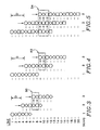
nozzles 30 in any order desired. However, only specially ordered configurations will result in all lines being printed once and only once by each color. Figs. 3 - 13 illustrate various arrangements that satisfy various ones of the desired features of a color printing system discussed earlier. In these figures, time is considered to progress from left to right. Thus, symbols shown on the same print line are considered to overlay each other, with the sequence of deposition occurring as determined by the deposition timing identified by sequential scans 1 - 3 or 4. - Figs. 3 and 4 illustrate two configurations for printing two colors with color interlacing. Fig. 3 shows two colors represented as circles and diamonds that simply alternate within a set of printing elements for printing line-by-line alternating colors. In order to provide for constant incremental movements of the print head relative to the print medium, the number N of nozzles must be odd.
- In Fig. 3, there are three nozzles of each color and the print head is shifted a distance D equal to the width of three lines between scans. The resulting overlay sequence is represented in the outlined
region 50. It can be seen that the overlay sequence alternates with every line, except for the band edges. - This method and configuration provide for band and line interlacing. The band of a particular color is 5 (2N-1 for N=3). Incrementing by N=3 lines is as close as possible to get to (2N-1)/2 lines when incrementing by an integer number of lines. Line interlacing results because each color is printed on only odd numbered lines in one scan and only on even numbered lines in the next scan, since the incremental distance change D is equivalent to the width of an odd number of lines.
- An alternative two-color printing configuration is shown in Fig. 4. The head color array is made up of two sets of four nozzles, with the nozzles alternating colors within each set, but with the placement of colors in each set reversed. For instance, during
scan 1, the color represented by a circle prints onlines lines 6 and 8 in the second set. As can be seen, the color in one set always prints on the odd lines and the same color in the other set always prints on the even lines. - As shown in outlined
region 52, the overlay sequence alternates every line. Considering that the band of circles encompasses eight lines, and that for diamonds encompasses six lines, the circles have near perfect band interlacing, whereas the diamonds have partial band interlacing. Also, it can be seen that the diamonds are printed on two consecutive lines during each scan. Otherwise line interlacing is also achieved. - Figs. 5 - 10 show different head configurations for printing three colors, such as the primary subtractive colors, cyan, magenta and yellow. Fig. 5 illustrates the case where the three colors alternate within a single set of nozzles. In order to avoid duplicate printing of some lines, N, the number of nozzles of each color, must not be an integer multiple of three. In the example shown, there are four nozzles of each color and the array is advanced the width D of four lines between scans.
- As shown by the outlined
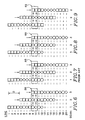
region 54, each line is only addressed once, and the overlay sequence of each color pair does not alternate perfectly line-by-line. The order of circle/square, square/diamond and diamond/circle repeats every two out of three lines. However, there is both band and line interlacing of each color. - The configuration shown in Fig. 6 is the same as that illustrated in Fig. 2 for the jets that print in color. Referring specifically to Fig. 6, three sets of four nozzles are used, with each set printing alternating lines of two colors. Each set prints a different one of the three pairs of colors: square/circle, diamond/square and circle/diamond. In the scan sequence shown,
lines 9 and 10 are the first lines to be overlaid by all three sets of nozzles. The resulting overlay sequence is represented in the outlinedregion 56. The ink drop locations in line 9 are addressed ("printed") first by the nozzle printing the color represented by the circle, followed by the nozzle printing a diamond and then by a nozzle printing a square. Thus, the circle is printed before both the diamond and the square, and the diamond is printed before the square. - Preferably, no more than two colors are printed at a single ink drop address location. Printing all three at one address results in "composite" or "three-color" black which always has a noticeable, dingy and repugnant hue. This arises because the subtractive primary colors are not ideal. Thus, it is better to print a single drop of pure black.
- In
line 10, the diamond is printed before the square and the circle, and the square is printed before the circle. This alternating pattern applies to all of the lines printed, as could be illustrated by continuing to draw columns forscans 4 and beyond. - Relating this to Fig. 2, diamonds (a first color) and circles (a second color) alternate in
first set 36 of print elements, squares (a third color) alternate with diamonds insecond set 37 of print elements, and circles alternate with squares inthird set 38. It will be seen that when a color is printed on odd lines in one set it is printed on even lines in a different set, so that all lines will be printed by each color. - The printing method illustrated in Fig. 6, and the print element array associated with it, provide for band interlacing of squares and diamonds, and line interlacing of all three colors. The bands of squares and diamonds each span thirty-two lines in this, the intended commercial embodiment. This array also provides a constant deposition order for one pair of colors (diamonds and squares), and provides alternative deposition orders for the other two pairs of colors (circles and diamonds, and circles and squares) on adjacent lines.
- In Fig. 7, each of print head sets 36, 37 and 38 have a single color, as is conventionally known. The first set is circles, the second set is diamonds, and the third set is squares. As shown in outlined
region 58, this results in the three colors being deposited in a constant order for all lines printed. That is, the circles are printed before both the diamonds and the squares, and the diamonds are printed before the squares. However, each color is neither band interlaced nor line interlaced. - Fig. 8 shows yet another embodiment, this one having the first two print element sets 36 and 37 alternating between circles and diamonds, and the
third set 38 all squares. As shown by outlined region 60, this embodiment provides both line and band interlacing for two colors (circles and diamonds) and a constant color overlay sequence for two of the color pairs (diamonds and squares, and circles and squares). However, the third color (squares) is neither line nor band interlaced. - In Fig. 9 the
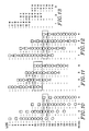
set 37 of printing elements printing a single color, diamonds in this case, is in the middle. The first andthird sets region 62, this configuration provides alternating overlay sequences for all three color pair combinations. However, one of the colors --diamonds-- is not line interlaced. There is no band interlacing at all. - The last three-color configuration is illustrated in Fig. 10. This configuration diverts from the previous configurations in which every line within the range of the print array is printed (addressed). This configuration requires four sets of nozzles. The two end sets each print a different single color on alternating lines. The two intermediate sets print alternating lines of two different color pairs. Four scans are required in order to have each line addressed by each of the colors, as is illustrated in outlined region 64.
- This configuration, though it requires a larger print head (4N-1 rather than 3N-1 address lines), provides a constant overlay sequence for all three colors. Further, there is band interlacing and line interlacing for all three colors.
- Figs. 11 - 13 illustrate configurations for printing four colors. In Fig. 11, there is a single set with the colors alternating in each set. If N, the number of nozzles per color, is even then the print head must be incremented on alternating scans by N-1 and N+1 lines. For N odd, regular increments of N lines after each scan provides printing of each color once on every line.
- N = 3 in the figure. As shown in outlined region 66, four scans are required in order to have every line addressed by every color. This results in three increments per band, which averages out any anomalies due to band edges. There also is complete line interlacing. However, the overlay sequences vary between not alternating at all to alternating every second line. The results are therefore inconsistent.
- Fig. 12 illustrates a preferred arrangement for printing four colors, where all four colors are given an equal number of nozzles. In this case a first set of four nozzles alternates between triangles and squares, the second set between diamonds and squares, the third set between diamonds and circles, and the last set between triangles and circles, as shown. The respective colors are assigned so that they print on even lines in one set and on odd lines in the other set in which they appear. A comparison on this configuration with the three-color configuration of Fig. 10 will show that they are identical as to the colors represented by squares, diamonds and circles. The triangles have been added where there were nozzle omissions in Fig. 10.
- As is apparent in the outlined region 68, the overlay sequence is the same for the three colors of Fig. 10. The sequences alternate every line for the combinations with the fourth color. This scheme would therefore be useful where black is assigned to the triangle positions and the three primary colors are assigned the other three symbol positions. This configuration produces line and partial band interlacing.
- Fig. 13 illustrates a configuration in which the four colors are treated as two sets of two colors. Each pair of colors, here yellow (Y) and black (K), and magenta (M) and cyan (C) are given the same array configuration as the two colors of Fig. 4. There are thus two sets for each color pair, with the two arrays printing on the same print lines. Alternatively, one two-color array could be positioned vertically, as represented here, to form a single line of both arrays so that there is a delay between the printing of color pairs. The print head in such an arrangement is, however, much less compact.
- The configuration of Fig. 13 is particularly desirable for hot-melt ink, where the inks combine when placed on top of or next to drops of ink that are not set. Since black is not applied to a spot that has another color, it is never combined on the same spot with other colors. The main color combinations alternate line-by-line except for yellow and magenta, which produce red, as shown by outlined region 70. This color pair stays the same on alternate two-line intervals. Since the eye is much less sensitive to red than to green, stripes or other anomalies will be less apparent. Alternatively, magenta and cyan, which produce blue, could also be used for this inconsistent color-overlay sequence pair. It is advantageous having cyan and yellow on different lines to allow the spots of ink to set between scans in order to produce a more consistent green.
- As suggested by the embodiment shown in Fig. 10, the nozzles could be vertically separated by twice the interline spacing so that no two color dots within the same array print on adjacent lines. This, however, doubles the size of the array.
- As has been indicated, the head arrays, numbers of sets of colors and numbers of each color in each set can be varied while practicing the present invention. It will therefore be appreciated that variations in form and detail may be made in the embodiments described without varying from the spirit and scope of the invention as defined in the claims.
Claims (10)
- A method of printing a color image on a print medium (22) along print lines ( 1, 2, 3, etc ) having centers spaced a predetermined interline distance apart, the method comprising the steps of:
printing on a first set (40) of print lines a first color and a second color, such that the colors alternate on the lines of the first set; and
printing on a second set (41) of print lines the first and second colors such that the colors alternate on the lines of the second set, while printing on the first set of print lines the first color on lines not printed previously with the first color. - A method according to claim 1 wherein the step of printing the first color on the first set (40) of print lines while printing on the second set (41) of print lines, includes printing the second color on the first set of print lines not printed previously with the second color.
- A method according to claim 1 further comprising the step of printing simultaneously third and fourth colors on the same lines on which the first and second colors are printed with the third and fourth colors being printed on alternating lines.
- A method according to claim 3 for printing with hot-melt ink, wherein the steps of printing the four colors includes printing magenta (M) and cyan (C) as the first and second colors and printing black (K) and yellow (Y) as the third and fourth colors.
- A method for printing a color image on a print medium (22) along print lines having centers spaced a predetermined interline distance apart, the method comprising the steps of:
printing on a first set (40) of print lines a first color and a second color, with the first and second colors being printed on respective alternate print lines;
during printing on the first set of print lines, printing on a third set (41) of print lines the first color and a third color, with the first and third colors being printed on respective alternate print lines; and
during printing on the first set of print lines, printing on a third set (42) of print lines the second color and the third color, with the second and third colors being printed on respective alternate print lines. - A method according to claim 5 wherein the steps of printing on the first, second, and third sets (40, 41, 42) of line is repeated on respective second, third, and fourth sets of print lines such that no print line is printed twice with the same color.
- A method according to claim 6 wherein the repeated steps of printing are further successively repeated on consecutive sets of print lines until each print line of the image is printed by the first, second, and third colors.
- An apparatus (10) for printing a color image formed of lines printed selectively over a predetermined area of a print medium (22), which lines have centers spaced a predetermined interline distance apart, the apparatus comprising:
a print head (16) movable relative to the print medium and having a first set (36) of printing elements (30), the set including a plurality of printing elements structured for printing simultaneously a corresponding plurality (40) of print lines, each printing element printing a color, and the set of printing elements printing two alternating colors; and
means (18) for moving the print head relative to a print medium in a manner such that all of the lines of the image are printed only once with each color. - An apparatus according to claim 8 wherein the print head (16) further includes a second set (37) of printing elements (30) for printing the same two alternating colors, the print head being structured so that, during a current pass of the print head, the second set of printing elements prints on the same lines as the first set of printing elements during a prior pass, with each line being printed only once with the same color.
- An apparatus according to claim 8 wherein the print head (16) further includes a second set (37) and a third set (38) of printing elements (30) for printing three colors, each set of printing elements printing a different pair of colors, with each pair of colors alternating within each set of printing elements.
Applications Claiming Priority (2)
| Application Number | Priority Date | Filing Date | Title |
|---|---|---|---|
| US528518 | 1990-05-25 | ||
| US07/528,518 US5059984A (en) | 1990-05-25 | 1990-05-25 | Method and apparatus for interlaced multicolor printing |
Publications (2)
| Publication Number | Publication Date |
|---|---|
| EP0458650A2 true EP0458650A2 (en) | 1991-11-27 |
| EP0458650A3 EP0458650A3 (en) | 1992-04-29 |
Family
ID=24106004
Family Applications (1)
| Application Number | Title | Priority Date | Filing Date |
|---|---|---|---|
| EP19910304735 Withdrawn EP0458650A3 (en) | 1990-05-25 | 1991-05-24 | Method and apparatus for interlaced multicolor printing |
Country Status (3)
| Country | Link |
|---|---|
| US (1) | US5059984A (en) |
| EP (1) | EP0458650A3 (en) |
| JP (1) | JP2651877B2 (en) |
Cited By (1)
| Publication number | Priority date | Publication date | Assignee | Title |
|---|---|---|---|---|
| EP0800923A2 (en) * | 1996-04-11 | 1997-10-15 | Mitsubishi Denki Kabushiki Kaisha | Multiple element printer and method of adjusting thereof |
Families Citing this family (29)
| Publication number | Priority date | Publication date | Assignee | Title |
|---|---|---|---|---|
| ATE157047T1 (en) * | 1991-06-07 | 1997-09-15 | Canon Kk | COLOR BEAM RECORDING METHOD AND APPARATUS |
| US5680167A (en) * | 1992-01-03 | 1997-10-21 | Eastman Kodak Company | Printing apparatus and method for tri-level color imaging |
| US5247315A (en) * | 1992-02-06 | 1993-09-21 | Gerber Scientific Products, Inc. | Method of printing a graphic having uniform ink density on an emulsion coated printing screen |
| EP0608429B1 (en) * | 1992-05-22 | 1996-10-09 | Seiko Epson Corporation | Color ink jet recording method |
| US5522016A (en) * | 1993-05-13 | 1996-05-28 | Dataproducts Corporation | Digitally controlled printing |
| US5485183A (en) * | 1993-06-30 | 1996-01-16 | Dataproducts Corporation | Interlaced dot-on-dot printing |
| US5625389A (en) * | 1994-01-31 | 1997-04-29 | Tektronix, Inc. | Ink-jet print head array and interlace method |
| US5805183A (en) * | 1994-11-10 | 1998-09-08 | Lasermaster Corporation | Ink jet printer with variable advance interlacing |
| US5831658A (en) * | 1995-03-30 | 1998-11-03 | Kabushiki Kaisha Tec | Printer device and method for printing deviation test patterns to measure deviations of printing positions |
| JP3606403B2 (en) * | 1995-04-27 | 2005-01-05 | セイコーエプソン株式会社 | Printing apparatus and printing method |
| JP3175539B2 (en) * | 1995-06-21 | 2001-06-11 | 富士ゼロックス株式会社 | Recording device and print control method |
| US5774144A (en) * | 1995-08-01 | 1998-06-30 | Tektronix, Inc. | Image interlacing and joining in a printer |
| US5734393A (en) * | 1995-08-01 | 1998-03-31 | Tektronix, Inc. | Interleaved interlaced imaging |
| US5949452A (en) * | 1996-11-27 | 1999-09-07 | Tektronix, Inc. | Interleaving image deposition method |
| JPH10235906A (en) * | 1997-02-25 | 1998-09-08 | Brother Ind Ltd | Recording head and image data recording method |
| US6592204B1 (en) | 1999-03-26 | 2003-07-15 | Spectra, Inc. | Single-pass inkjet printing |
| US6575558B1 (en) * | 1999-03-26 | 2003-06-10 | Spectra, Inc. | Single-pass inkjet printing |
| US6238037B1 (en) | 2000-02-07 | 2001-05-29 | Lexmark International, Inc. | Method of multi-dot interlace printing |
| JP4221921B2 (en) * | 2001-08-23 | 2009-02-12 | ブラザー工業株式会社 | Printing device |
| US6874860B2 (en) * | 2001-10-25 | 2005-04-05 | Vutek, Incorporated | Multi-speed, multi-resolution print heads |
| US6679583B2 (en) * | 2001-10-31 | 2004-01-20 | Agfa-Gevaert | Fast mutually interstitial printing |
| US6682172B2 (en) * | 2001-10-31 | 2004-01-27 | Agfa-Gevaert | Method and apparatus for maintaining colour sequence when printing |
| US6712442B1 (en) | 2002-09-23 | 2004-03-30 | Lexmark International, Inc. | Method of image rasterization and imaging an address space an ink jet printers |
| US6918653B2 (en) * | 2003-05-22 | 2005-07-19 | Lexmark International, Inc. | Multi-fluid jetting device |
| US7771010B2 (en) * | 2006-02-03 | 2010-08-10 | Rr Donnelley | Apparatus for printing using a plurality of printing cartridges |
| EP2352651B1 (en) * | 2008-12-03 | 2017-03-29 | Videojet Technologies, Inc. | An inkjet printing system and method |
| EP2741917B1 (en) | 2011-08-12 | 2019-05-22 | R. R. Donnelley & Sons Company | Apparatus and method for disposing inkjet cartridges in a carrier |
| US11640615B2 (en) | 2016-09-08 | 2023-05-02 | Thomas Villwock | Methods and systems for authenticating goods and services using electronic analysis of analyte encoded compositions |
| EP3509848A4 (en) * | 2016-09-08 | 2020-06-03 | Thomas Villwock | Methods and systems for authenticating goods using analyte encoded security fluids |
Citations (6)
| Publication number | Priority date | Publication date | Assignee | Title |
|---|---|---|---|---|
| JPS5689950A (en) * | 1979-12-25 | 1981-07-21 | Fujitsu Ltd | Color ink jet printer |
| US4540996A (en) * | 1982-05-11 | 1985-09-10 | Canon Kabushiki Kaisha | Recording apparatus |
| JPS60253551A (en) * | 1984-05-30 | 1985-12-14 | Canon Inc | Color image recording system |
| US4593295A (en) * | 1982-06-08 | 1986-06-03 | Canon Kabushiki Kaisha | Ink jet image recording device with pitch-shifted recording elements |
| US4864328A (en) * | 1988-09-06 | 1989-09-05 | Spectra, Inc. | Dual mode ink jet printer |
| US4965593A (en) * | 1989-07-27 | 1990-10-23 | Hewlett-Packard Company | Print quality of dot printers |
Family Cites Families (11)
| Publication number | Priority date | Publication date | Assignee | Title |
|---|---|---|---|---|
| JPS58138656A (en) * | 1982-02-12 | 1983-08-17 | Canon Inc | Recorder |
| US4528576A (en) * | 1982-04-15 | 1985-07-09 | Canon Kabushiki Kaisha | Recording apparatus |
| JPS58194575A (en) * | 1982-05-11 | 1983-11-12 | Ricoh Co Ltd | Color plotter |
| JPS59115853A (en) * | 1982-12-23 | 1984-07-04 | Sharp Corp | Ink jet recording apparatus |
| US4680596A (en) * | 1984-08-02 | 1987-07-14 | Metromedia Company | Method and apparatus for controlling ink-jet color printing heads |
| US4741930A (en) * | 1984-12-31 | 1988-05-03 | Howtek, Inc. | Ink jet color printing method |
| US4714936A (en) * | 1985-06-24 | 1987-12-22 | Howtek, Inc. | Ink jet printer |
| US4728968A (en) * | 1985-08-30 | 1988-03-01 | Siemens Aktiengesellschaft | Arrangement of discharge openings in a printhead of a multi-color ink printer |
| US4812859A (en) * | 1987-09-17 | 1989-03-14 | Hewlett-Packard Company | Multi-chamber ink jet recording head for color use |
| US4967203A (en) * | 1989-09-29 | 1990-10-30 | Hewlett-Packard Company | Interlace printing process |
| US4978971A (en) * | 1989-11-06 | 1990-12-18 | Tektronix, Inc. | Method and apparatus for reformatting print data |
-
1990
- 1990-05-25 US US07/528,518 patent/US5059984A/en not_active Expired - Lifetime
-
1991
- 1991-05-24 EP EP19910304735 patent/EP0458650A3/en not_active Withdrawn
- 1991-05-24 JP JP3149381A patent/JP2651877B2/en not_active Expired - Fee Related
Patent Citations (6)
| Publication number | Priority date | Publication date | Assignee | Title |
|---|---|---|---|---|
| JPS5689950A (en) * | 1979-12-25 | 1981-07-21 | Fujitsu Ltd | Color ink jet printer |
| US4540996A (en) * | 1982-05-11 | 1985-09-10 | Canon Kabushiki Kaisha | Recording apparatus |
| US4593295A (en) * | 1982-06-08 | 1986-06-03 | Canon Kabushiki Kaisha | Ink jet image recording device with pitch-shifted recording elements |
| JPS60253551A (en) * | 1984-05-30 | 1985-12-14 | Canon Inc | Color image recording system |
| US4864328A (en) * | 1988-09-06 | 1989-09-05 | Spectra, Inc. | Dual mode ink jet printer |
| US4965593A (en) * | 1989-07-27 | 1990-10-23 | Hewlett-Packard Company | Print quality of dot printers |
Non-Patent Citations (2)
| Title |
|---|
| PATENT ABSTRACTS OF JAPAN vol. 10, no. 126 (M-477)(2183) 10 May 1986 & JP-A-60 253 551 ( CANON ) 14 December 1985 * |
| PATENT ABSTRACTS OF JAPAN vol. 5, no. 162 (M-92)17 October 1981 & JP-A-56 089 950 ( FUJITSU ) 21 July 1981 * |
Cited By (3)
| Publication number | Priority date | Publication date | Assignee | Title |
|---|---|---|---|---|
| EP0800923A2 (en) * | 1996-04-11 | 1997-10-15 | Mitsubishi Denki Kabushiki Kaisha | Multiple element printer and method of adjusting thereof |
| EP0800923A3 (en) * | 1996-04-11 | 1998-05-06 | Mitsubishi Denki Kabushiki Kaisha | Multiple element printer and method of adjusting thereof |
| US5988790A (en) * | 1996-04-11 | 1999-11-23 | Mitsubishi Denki Kabushiki Kaisha | Multiple element printer and method of adjusting thereof |
Also Published As
| Publication number | Publication date |
|---|---|
| JP2651877B2 (en) | 1997-09-10 |
| US5059984A (en) | 1991-10-22 |
| JPH04226367A (en) | 1992-08-17 |
| EP0458650A3 (en) | 1992-04-29 |
Similar Documents
| Publication | Publication Date | Title |
|---|---|---|
| US5059984A (en) | Method and apparatus for interlaced multicolor printing | |
| US5079571A (en) | Interlaced printing using spaced print arrays | |
| EP0665114B1 (en) | Interlace printing method | |
| EP0526186B1 (en) | Ink jet recording method | |
| US5075689A (en) | Bidirectional hot melt ink jet printing | |
| US4864328A (en) | Dual mode ink jet printer | |
| EP0865927B1 (en) | Printing apparatus and printing method using multiple nozzle groups | |
| US5485183A (en) | Interlaced dot-on-dot printing | |
| JP2001080093A (en) | Method for compensating for hue shift in bi-directional printer and apparatus therefor | |
| JPH0755560B2 (en) | Inkjet printer | |
| EP0899681B1 (en) | Method of printing with an ink jet printer using an enhanced horizontal resolution | |
| EP0497614B1 (en) | Method for high-speed interlaced printing along the axis of print head scanning | |
| EP0723872B1 (en) | Pairing of ink drops on a print medium | |
| US6315388B1 (en) | Draft printing | |
| EP0661870A1 (en) | Method and apparatus for liquid ink recording of images with black ink and color inks | |
| JPH06135013A (en) | Ink jet recording method employing multicolor inks | |
| JPH1148503A (en) | Ink-jet recording head and ink-jet recording apparatus | |
| JPH0376226B2 (en) | ||
| EP0671699A2 (en) | Bidirectional color ink jet printing with head signature reduction | |
| JPS58194540A (en) | Recording apparatus | |
| JP3070352B2 (en) | Print processing method of inkjet recording device | |
| KR20020030783A (en) | Method for the formation of coloured pixels and print head and inkjet printing device for application of the method | |
| JPH10157095A (en) | Integrity of external dimension of color ink jet printer for attaining high resolution address designating capability | |
| JPH06183129A (en) | Ink jet recording method and device therefor | |
| JPH0415098B2 (en) |
Legal Events
| Date | Code | Title | Description |
|---|---|---|---|
| PUAI | Public reference made under article 153(3) epc to a published international application that has entered the european phase |
Free format text: ORIGINAL CODE: 0009012 |
|
| AK | Designated contracting states |
Kind code of ref document: A2 Designated state(s): CH DE FR GB IT LI |
|
| PUAL | Search report despatched |
Free format text: ORIGINAL CODE: 0009013 |
|
| AK | Designated contracting states |
Kind code of ref document: A3 Designated state(s): CH DE FR GB IT LI |
|
| 17P | Request for examination filed |
Effective date: 19921026 |
|
| 17Q | First examination report despatched |
Effective date: 19950203 |
|
| STAA | Information on the status of an ep patent application or granted ep patent |
Free format text: STATUS: THE APPLICATION IS DEEMED TO BE WITHDRAWN |
|
| 18D | Application deemed to be withdrawn |
Effective date: 19970304 |