EP0468374A2 - Rotary shear - Google Patents
Rotary shear Download PDFInfo
- Publication number
- EP0468374A2 EP0468374A2 EP91112070A EP91112070A EP0468374A2 EP 0468374 A2 EP0468374 A2 EP 0468374A2 EP 91112070 A EP91112070 A EP 91112070A EP 91112070 A EP91112070 A EP 91112070A EP 0468374 A2 EP0468374 A2 EP 0468374A2
- Authority
- EP
- European Patent Office
- Prior art keywords
- corrugated cardboard
- cardboard web
- traveling
- rotary shear
- knife
- Prior art date
- Legal status (The legal status is an assumption and is not a legal conclusion. Google has not performed a legal analysis and makes no representation as to the accuracy of the status listed.)
- Granted
Links
Images

Classifications
-
- B—PERFORMING OPERATIONS; TRANSPORTING
- B26—HAND CUTTING TOOLS; CUTTING; SEVERING
- B26D—CUTTING; DETAILS COMMON TO MACHINES FOR PERFORATING, PUNCHING, CUTTING-OUT, STAMPING-OUT OR SEVERING
- B26D1/00—Cutting through work characterised by the nature or movement of the cutting member or particular materials not otherwise provided for; Apparatus or machines therefor; Cutting members therefor
- B26D1/01—Cutting through work characterised by the nature or movement of the cutting member or particular materials not otherwise provided for; Apparatus or machines therefor; Cutting members therefor involving a cutting member which does not travel with the work
- B26D1/12—Cutting through work characterised by the nature or movement of the cutting member or particular materials not otherwise provided for; Apparatus or machines therefor; Cutting members therefor involving a cutting member which does not travel with the work having a cutting member moving about an axis
- B26D1/25—Cutting through work characterised by the nature or movement of the cutting member or particular materials not otherwise provided for; Apparatus or machines therefor; Cutting members therefor involving a cutting member which does not travel with the work having a cutting member moving about an axis with a non-circular cutting member
- B26D1/34—Cutting through work characterised by the nature or movement of the cutting member or particular materials not otherwise provided for; Apparatus or machines therefor; Cutting members therefor involving a cutting member which does not travel with the work having a cutting member moving about an axis with a non-circular cutting member moving about an axis parallel to the line of cut
- B26D1/38—Cutting through work characterised by the nature or movement of the cutting member or particular materials not otherwise provided for; Apparatus or machines therefor; Cutting members therefor involving a cutting member which does not travel with the work having a cutting member moving about an axis with a non-circular cutting member moving about an axis parallel to the line of cut and coacting with a fixed blade or other fixed member
- B26D1/385—Cutting through work characterised by the nature or movement of the cutting member or particular materials not otherwise provided for; Apparatus or machines therefor; Cutting members therefor involving a cutting member which does not travel with the work having a cutting member moving about an axis with a non-circular cutting member moving about an axis parallel to the line of cut and coacting with a fixed blade or other fixed member for thin material, e.g. for sheets, strips or the like
-
- B—PERFORMING OPERATIONS; TRANSPORTING
- B26—HAND CUTTING TOOLS; CUTTING; SEVERING
- B26D—CUTTING; DETAILS COMMON TO MACHINES FOR PERFORATING, PUNCHING, CUTTING-OUT, STAMPING-OUT OR SEVERING
- B26D7/00—Details of apparatus for cutting, cutting-out, stamping-out, punching, perforating, or severing by means other than cutting
- B26D7/20—Cutting beds
-
- B—PERFORMING OPERATIONS; TRANSPORTING
- B26—HAND CUTTING TOOLS; CUTTING; SEVERING
- B26D—CUTTING; DETAILS COMMON TO MACHINES FOR PERFORATING, PUNCHING, CUTTING-OUT, STAMPING-OUT OR SEVERING
- B26D9/00—Cutting apparatus combined with punching or perforating apparatus or with dissimilar cutting apparatus
-
- B—PERFORMING OPERATIONS; TRANSPORTING
- B26—HAND CUTTING TOOLS; CUTTING; SEVERING
- B26D—CUTTING; DETAILS COMMON TO MACHINES FOR PERFORATING, PUNCHING, CUTTING-OUT, STAMPING-OUT OR SEVERING
- B26D7/00—Details of apparatus for cutting, cutting-out, stamping-out, punching, perforating, or severing by means other than cutting
- B26D7/20—Cutting beds
- B26D2007/202—Rollers or cylinders being pivoted during operation
-
- B—PERFORMING OPERATIONS; TRANSPORTING
- B26—HAND CUTTING TOOLS; CUTTING; SEVERING
- B26D—CUTTING; DETAILS COMMON TO MACHINES FOR PERFORATING, PUNCHING, CUTTING-OUT, STAMPING-OUT OR SEVERING
- B26D11/00—Combinations of several similar cutting apparatus
- B26D2011/005—Combinations of several similar cutting apparatus in combination with different kind of cutters, e.g. two serial slitters in combination with a transversal cutter
-
- Y—GENERAL TAGGING OF NEW TECHNOLOGICAL DEVELOPMENTS; GENERAL TAGGING OF CROSS-SECTIONAL TECHNOLOGIES SPANNING OVER SEVERAL SECTIONS OF THE IPC; TECHNICAL SUBJECTS COVERED BY FORMER USPC CROSS-REFERENCE ART COLLECTIONS [XRACs] AND DIGESTS
- Y10—TECHNICAL SUBJECTS COVERED BY FORMER USPC
- Y10T—TECHNICAL SUBJECTS COVERED BY FORMER US CLASSIFICATION
- Y10T83/00—Cutting
- Y10T83/465—Cutting motion of tool has component in direction of moving work
- Y10T83/4708—With means to render cutter pass[es] ineffective
-
- Y—GENERAL TAGGING OF NEW TECHNOLOGICAL DEVELOPMENTS; GENERAL TAGGING OF CROSS-SECTIONAL TECHNOLOGIES SPANNING OVER SEVERAL SECTIONS OF THE IPC; TECHNICAL SUBJECTS COVERED BY FORMER USPC CROSS-REFERENCE ART COLLECTIONS [XRACs] AND DIGESTS
- Y10—TECHNICAL SUBJECTS COVERED BY FORMER USPC
- Y10T—TECHNICAL SUBJECTS COVERED BY FORMER US CLASSIFICATION
- Y10T83/00—Cutting
- Y10T83/465—Cutting motion of tool has component in direction of moving work
- Y10T83/4766—Orbital motion of cutting blade
- Y10T83/4795—Rotary tool
- Y10T83/4847—With cooperating stationary tool
-
- Y—GENERAL TAGGING OF NEW TECHNOLOGICAL DEVELOPMENTS; GENERAL TAGGING OF CROSS-SECTIONAL TECHNOLOGIES SPANNING OVER SEVERAL SECTIONS OF THE IPC; TECHNICAL SUBJECTS COVERED BY FORMER USPC CROSS-REFERENCE ART COLLECTIONS [XRACs] AND DIGESTS
- Y10—TECHNICAL SUBJECTS COVERED BY FORMER USPC
- Y10T—TECHNICAL SUBJECTS COVERED BY FORMER US CLASSIFICATION
- Y10T83/00—Cutting
- Y10T83/929—Tool or tool with support
- Y10T83/9309—Anvil
Definitions
- the present invention relates to a rotary shear installed in a corrugating machine for performing slotting work or cutting work upon a continuously traveling corrugated cardboard web nearly at right angles thereto.
- the rotary shear is an apparatus for cutting a corrugated cardboard web 17 manufactured continuously in a corrugating machine in the preceding step or performing slotting work thereto along the widthwise direction of the web, and it mainly operates at the time of order change and it functions to deal with switching of setting such as width change of trims 21 or sheets 20.
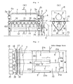
- a knife cylinder 2 having a knife 1 fixedly secured thereto has its opposite ends pivotably supported from frames 4a and 4b erected at the opposite width ends of the apparatus via bearings 3a and 3b, respectively, and to an outermost end of its shaft on one side is connected a shaft 6 via an electromagnetic clutch brake 5.
- a pulley 7 On the shaft 6 is mounted a pulley 7, and the pulley 7 is coupled to a pulley 10 fixedly secured to a line shaft 8 or a shaft 8 of a motor 9 serving as an independent drive unit, via an endless synchronizing bell 11 wound therearound.
- an anvil cylinder 22 has its opposite ends pivotably supported from the frames 4a and 4b, respectively, via bearings 23a and 23b in parallel to the above-described knife cylinder 2.
- a pulley 24 To one side end of the anvil cylinder 22 is fixedly secured a pulley 24, and this pulley is coupled to a pulley 27 on a shaft 26 pivotably supported from the frame 4a via a belt 25.
- the above-mentioned shaft 26 is connected to an indexing motor 29 via an electromagnetic clutch brake 28.
- Reference numeral 12 designates an endless elastic body belt, which comes into slide contact with the outer circumferential surfaces of the knife cylinder 2 and the anvil cylinder 22, and is wound around a plurality of rolls 14 having their opposite shaft ends pivotably supported from the frames 4a and 4b.
- the width of the above-mentioned belt 12 is made equal to or somewhat broader than that of the knife 1 on the knife cylinder 2, and the arrangement is such that the belt 12 can travel at a predetermined speed (a traveling speed of the corrugated cardboard web 17) by making a gear 15 provided at a shaft end of the roll 14 mesh with a gear 16 fixedly secured to the shaft 8 of the driving motor 9.
- the surface of the above-mentioned anvil cylinder 22 has a configuration shown in Fig.
- a central portion of an elastic body 30 is removed on a part of the circumferential surface so that the width of the removed part may successively decrease from a portion S extending over the entire width up to a predetermined dimension So, and a step (a recess and a ridge) is formed.
- the portion corresponding to a dimension P is a recessed portion formed on the cylindrical surface of the anvil cylinder 22, accordingly in this interval a pinching force (shearing force) between the knife 1 and the anvil cylinder 22 would not be generated, and so, cutting cannot be done.
- the rotary shear of the illustrated type can machine slots having an arbitrary length of from zero to a maximum (W-S o )/2 at the opposite width ends of the corrugated cardboard web 17.
- the phase of the knife 1 is matched to the traveling corrugated cardboard web 17, and the electromagnetic clutch brake 5 is connected.
- the rotational behavior of the knife cylinder 2 is such that it can be rotated or stopped at a predetermined timing by operating (connecting or disconnecting) the electromagnetic clutch brake 5.
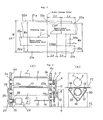
- Fig. 9 is a schematic side view of a slitter-scorer positioned in the next stage
- Fig. 8 is a schematic plan view depicted at a position corresponding vertically to Fig. 9 as viewed on the same sheet of drawing for illustrating a machined condition of the corrugated cardboard web.
- a slitter-scorer P is an apparatus for machining predetermined score lines K and slitting slots S on a traveling corrugated cardboard web 17 as shown in Fig.
- FIG. 8 illustrates the case of two-sheet production.
- the rotary shear in the prior art was one operated as a trim shear to be used for cutting of the tip ends of the trims 21 b on the side of the new order, which is necessitated mainly upon switching of the slitter-scorers P a and P b according to order change, that is, upon change of processing of the trims 21 which are formed depending upon a width W of the corrugated cardboard web being produced and a width W o of the product sheets.
- a trimming position resulted from order change is transmitted as a signal from an order change system controller not shown, in the slitter-scorer P b under a stand-by condition, various settings corresponding to a new order are carried out besides position setting of a trim duct 33b, and at the same time in a trim cutting device (rotary shear), a relative angular position of the anvil cylinder 22 is set with respect to position of the knife 1 so as to set slitting lengths at the opposite width ends of the corrugated cardboard web corresponding to the new order.
- the knife cylinder 2 and the elastic body belt 12 are rotated in the opposite directions at a predetermined timing matched with passage of the traveling corrugated cardboard web 17, and trim cutting notches are formed at the desired positions.
- the above-mentioned notched positions are transferred the slitter-scorer P b under a stand-by condition, at a predetermined position at first the scoring rolls 31 are meshed, subsequently the slitter knives 32b are meshed, and sequentially works according to the new order are applied.
- the rotary shear in the prior art was constructed and operated in the above-described manner, and it had only two kinds of functions of slitting by an arbitrary length at the opposite width ends of a traveling corrugated cardboard web or perfectly cutting the web over its entire width. Accordingly, in the setting for two-sheet production as shown in Fig.
- a specification can be switched stably only under a limited condition such that only a trim width at the width ends is changed as a result of order change, that is, a sheet separating slit slot has a continuous shape, that even if a sheet separating slit slot should become discontinuous as a result of change of a sheet width, cut lengths of the two sheets traveling in parallel are the same, or that only one kind of sheets are produced from a single web, though not shown.
- a discontinuous portion X would remain in the central slitting slot, and so, upon change of the traveling route (separation to upper and lower routes) at the cut-off D in the downstream stage which is executed in the case where the lengths of the above-mentioned sheets traveling in parallel are different from each other, troubles would frequently occur such that not only the above-mentioned discontinuous portion is broken and becomes unacceptable paper sheets, but also the broken pieces of paper sheets are caught by downstream conveyor means (feed rolls) resulting in jam-up.
- the above-described rotary shear in the prior art could perform only two kinds of cutting work of machining slots in the widthwise direction of a sheet at the opposite width ends of a corrugated cardboard web, or perfectly cutting the web over the entire width of the sheet.
- the rotary shear could deal with stably under a limited condition as in the case where only trim widths are changed according to order change, in multiple-sheet production of producing, for instance, two kinds (a plurality of kinds) of sheets from a single corrugated cardboard sheet, in the case where widths of the sheets are changed as a result of order change and also cut sheet lengths are different, there was a disadvantage that at the changing point between the new and old orders, the slitting position would be displaced in the widthwise direction of the sheet, resulting in a discontinuous portion, hence the sheets would broken due to separation of the sheet traveling routes to the upper and lower routes at the cut-off in the subsequent stage, and it would become unacceptable paper sheets. Furthermore, it became a principal cause of various troubles such that the broken pieces of the paper sheets may block the gap between conveyor rolls in the subsequent stage and may result in jam-up or the like.
- a more specific object of the present invention is to provide a rotary shear which can smoothly follow order change without necessitating to perfectly cut a web over its entire width, even in the case where two or more kinds of sheets having different cut lengths are produced from a single web.
- Another specific object of the present invention is to provide a rotary shear, in which deterioration of a precision in a cut length caused by unstability of traveling of sheets upon order change, can be eliminated.
- a rotary shear for performing slotting work or cutting work upon a corrugated cardboard web produced continuously by a corrugating machine nearly at right angles to the traveling direction of the corrugated cardboard web, which comprises a knife cylinder having a knife fixedly secured thereto over the nearly entire width of the outer circumferential surface of the cylinder, pressing means divided into a plurality of sections along the widthwise direction of the corrugated cardboard web and constructed in such manner that the respective sections can be individually raised and lowered, and an endless elastic body belt driven to travel at a predetermined timing with respect to the traveling corrugated cardboard web.
- the present invention in the case where dimensions of trim widths at the opposite side edges of a corrugated cardboard web have been changed according to order change, or in the case where sheet widths are changed in a multiple-sheet production for producing a plurality of kinds of sheets having different cut lengths, since slitting slots in the widthwise direction of the sheet can be formed only at necessary portions, even if the new and old sheets are not separated perfectly according to order change as is the case with the prior art, disadvantages such as breaking of the sheets at the point of change of a specification, would be eliminated. Accordingly, the sheets can be conveyed stably, and also, troubles such as jam-up or the like can be eliminated.
- a knife cylinder 2 having a knife 1 fixedly secured thereto has its opposite ends pivotably supported from frames 4a and 4b erected at the opposite side edge of the apparatus via bearings 3a and 3b, and to the outermost end on one side thereof is connected a shaft 6 via an electromagnetic clutch brake 5.
- a pulley 7 is coupled to a pulley 10 fixedly secured to a line shaft not shown or a shaft 8 of a motor 9 serving as an independent drive unit by means of an endless synchronizing belt 11 wound therearound.
- an endless elastic body belt 12 is mounted as wound around a plurality of rolls 14 disposed in parallel to the above-mentioned knife cylinder 2 and having the opposite ends of their shafts pivotably supported from the frames 4a and 4b via bearings 13a and 13b, respectively.
- the width of the elastic body belt 12 is made equal to or somewhat broader than the knife 1 on the knife cylinder 2, and the belt 12 is constructed so as to be able to travel at a predetermined speed (a traveling speed of the corrugated cardboard web 17) by meshing a gear 15 fixedly secured to one end of the shaft of the roll 14 with a gear 16 mounted to the above-described line shaft or the shaft 8 of the driving motor 9.
- reference numeral 18 designated pressing means, in which respective sections divided along the widthwise direction of the corrugated cardboard web 17 can be individually raised or lowered by an expansion/contraction operation of cylinders 19 such as hydraulic cylinders fixedly secured to the bottom surfaces of the sections.
- slots having predetermined lengths can be machined at desired positions. More particularly, to the corrugated cardboard web 17 traveling between the elastic body belt 12 and the knife cylinder 2, acts a pinching and cutting force of the knife 1 only at to the portion (width portion) where the pressing means 18 has been raised and set, but at the portion where the pressing means 18 is set at the lowered position, a cutting force would not act due to deformation (escape) of the elastic body belt 12.
- the corrugated cardboard web 17 is held in a state where slots in the widthwise direction are formed only at necessary portions, and it would be conveyed to the downstream stage as continuous corrugated cardboard sheets 20 as a whole. It is to be noted that if all the cylinders 19 corresponding to the width of the corrugated cardboard web 17 are actuated so as to press and all the pressing plates 18 are raised and set as shown in Fig. 1, then perfect cutting over the entire region in the widthwise direction is also possible, and the apparatus can quickly respond to an unexpectable accident such as production of unacceptable paper sheets.
- the method illustrated in Fig. 1 (a) is of such type that the shaft 8 and the roll 14 are directly coupled via the gears 15 and 16 and the belt 12 are made to always rotationally travel, but various other methods can be conceived such that the belt 12 may be driven to travel only just before and after the time for cutting by assembling a clutch not shown between the shaft 8 and the roll 14. Also, the raising and lowering means for the pressing means 18 should not be limited to the illustrated cylinders 19.
- the present invention since the present invention has structural and functional features as described above, the slitting slots in the widthwise direction of the sheets which become necessary upon order change can be formed at arbitrary positions, and even in the case where two or more kinds of sheets having different cutting lengths are produced from a single corrugated cardboard sheet, smooth order change can be achieved even if the web is not perfectly cut over the entire region in the widthwise direction as is the case with the prior art.
Abstract
Description
- The present invention relates to a rotary shear installed in a corrugating machine for performing slotting work or cutting work upon a continuously traveling corrugated cardboard web nearly at right angles thereto.
- One example of a rotary shear in the prior art is illustrated in Figs. 4 to 7. The rotary shear is an apparatus for cutting a
corrugated cardboard web 17 manufactured continuously in a corrugating machine in the preceding step or performing slotting work thereto along the widthwise direction of the web, and it mainly operates at the time of order change and it functions to deal with switching of setting such as width change of trims 21 orsheets 20. - In the following, description will be made on a general construction and a function of a rotary shear in the prior art. As shown in Fig. 4, a
knife cylinder 2 having aknife 1 fixedly secured thereto has its opposite ends pivotably supported fromframes bearings electromagnetic clutch brake 5. On the shaft 6 is mounted apulley 7, and thepulley 7 is coupled to apulley 10 fixedly secured to aline shaft 8 or ashaft 8 of amotor 9 serving as an independent drive unit, via an endless synchronizingbell 11 wound therearound. - On the other hand, an
anvil cylinder 22 has its opposite ends pivotably supported from theframes bearings knife cylinder 2. To one side end of theanvil cylinder 22 is fixedly secured apulley 24, and this pulley is coupled to apulley 27 on ashaft 26 pivotably supported from theframe 4a via abelt 25. In addition, the above-mentionedshaft 26 is connected to an indexingmotor 29 via anelectromagnetic clutch brake 28.Reference numeral 12 designates an endless elastic body belt, which comes into slide contact with the outer circumferential surfaces of theknife cylinder 2 and theanvil cylinder 22, and is wound around a plurality ofrolls 14 having their opposite shaft ends pivotably supported from theframes belt 12 is made equal to or somewhat broader than that of theknife 1 on theknife cylinder 2, and the arrangement is such that thebelt 12 can travel at a predetermined speed (a traveling speed of the corrugated cardboard web 17) by making agear 15 provided at a shaft end of theroll 14 mesh with agear 16 fixedly secured to theshaft 8 of thedriving motor 9. The surface of the above-mentionedanvil cylinder 22 has a configuration shown in Fig. 5, in which as shown in a developed state in Fig. 6, a central portion of anelastic body 30 is removed on a part of the circumferential surface so that the width of the removed part may successively decrease from a portion S extending over the entire width up to a predetermined dimension So, and a step (a recess and a ridge) is formed. - Accordingly, by variable setting the phase relationship between the
knife 1 of theknife cylinder 2 and theanvil cylinder 22, two kinds of cutting works as shown in Fig. 7 becomes possible. More particularly, if theanvil cylinder 22 is engaged with theknife 1 at a position A in Fig. 6, then cutting over the entire width is possible, while if it is engaged with theknife 1 at a position B in the same figure, then at the opposite width end portions of thecorrugated cardboard web 17, slits (slots) having a length corresponding to a dimension Po in Fig. 6 can be formed. It is to be noted that in Fig. 6 the portion corresponding to a dimension P is a recessed portion formed on the cylindrical surface of theanvil cylinder 22, accordingly in this interval a pinching force (shearing force) between theknife 1 and theanvil cylinder 22 would not be generated, and so, cutting cannot be done. In addition, by appropriately variably setting the position B where theanvil cylinder 22 is engaged with theknife 1, the rotary shear of the illustrated type can machine slots having an arbitrary length of from zero to a maximum (W-So)/2 at the opposite width ends of thecorrugated cardboard web 17. - Next, description will be made on an operation of the rotary shear in the prior art shown in Fig. 4. As initial setting of the rotary shear, at first the
electromagnetic clutch brake 28 is connected, then theanvil cylinder 22 is rotated by driving the indexingmotor 29 and a phase to be engaged with theknife 1 is set (indexed), and under that condition, the brake of the above-mentionedclutch brake 28 is actuated and thereby theanvil cylinder 22 is held at a fixed position. - Subsequently, the phase of the
knife 1 is matched to the travelingcorrugated cardboard web 17, and theelectromagnetic clutch brake 5 is connected. The rotational behavior of theknife cylinder 2 is such that it can be rotated or stopped at a predetermined timing by operating (connecting or disconnecting) theelectromagnetic clutch brake 5. - Fig. 9 is a schematic side view of a slitter-scorer positioned in the next stage, and Fig. 8 is a schematic plan view depicted at a position corresponding vertically to Fig. 9 as viewed on the same sheet of drawing for illustrating a machined condition of the corrugated cardboard web. A slitter-scorer P is an apparatus for machining predetermined score lines K and slitting slots S on a traveling
corrugated cardboard web 17 as shown in Fig. 8 by means of equipped scoring rolls 31 and slitter knives 32, and by appropriately selecting a corrugated cardboard web width W in relation to a necessitated product sheet width Wo, production of a plurality of sheets (multiple sheet production) can be done simultaneously (Fig. 8 illustrates the case of two-sheet production). - In addition, in order to achieve shortening of time for resetting according to order change, often two slitter-scorers Pa and Pb are installed as aligned in the traveling direction of the sheets. It is to be noted that the entire width W of the above-described corrugated cardboard web to be produced was set somewhat broader than the width Wo to be used as product sheets, and the opposite width end portions where faults such as displacement upon sticking of the original paper sheets, squeezing-out of paste and the like are liable to occur, are cut in a belt shape, and they are sucked into respective trim ducts 33 as trims (broke wastes) 21 and processed. The rotary shear in the prior art was one operated as a trim shear to be used for cutting of the tip ends of the
trims 21 b on the side of the new order, which is necessitated mainly upon switching of the slitter-scorers Pa and Pb according to order change, that is, upon change of processing of the trims 21 which are formed depending upon a width W of the corrugated cardboard web being produced and a width Wo of the product sheets. - Next, brief description will be made on change of setting of a rotary shear in the prior art. A trimming position resulted from order change is transmitted as a signal from an order change system controller not shown, in the slitter-scorer Pb under a stand-by condition, various settings corresponding to a new order are carried out besides position setting of a
trim duct 33b, and at the same time in a trim cutting device (rotary shear), a relative angular position of theanvil cylinder 22 is set with respect to position of theknife 1 so as to set slitting lengths at the opposite width ends of the corrugated cardboard web corresponding to the new order. - Then, the
knife cylinder 2 and theelastic body belt 12 are rotated in the opposite directions at a predetermined timing matched with passage of the travelingcorrugated cardboard web 17, and trim cutting notches are formed at the desired positions. Next, the above-mentioned notched positions are transferred the slitter-scorer Pb under a stand-by condition, at a predetermined position at first the scoring rolls 31 are meshed, subsequently theslitter knives 32b are meshed, and sequentially works according to the new order are applied. On the other hand, in the slitter-scorer Pa working according to the old order, at a predetermined timing when the leading end of the corrugated cardboard sheet according to the new order arrives, the engagements of thescoring rolls 31 a and theslitter knives 32a are sequentially released. In addition, new trims 21 produced from thecorrugated cardboard web 17 according to the new order are respectively sucked and conveyed by a pair of newly settrim ducts 33b, and after they have been shredded by a cutter-blower 34 provided in the passageway, they are processed. - The rotary shear in the prior art was constructed and operated in the above-described manner, and it had only two kinds of functions of slitting by an arbitrary length at the opposite width ends of a traveling corrugated cardboard web or perfectly cutting the web over its entire width. Accordingly, in the setting for two-sheet production as shown in Fig. 8, a specification can be switched stably only under a limited condition such that only a trim width at the width ends is changed as a result of order change, that is, a sheet separating slit slot has a continuous shape, that even if a sheet separating slit slot should become discontinuous as a result of change of a sheet width, cut lengths of the two sheets traveling in parallel are the same, or that only one kind of sheets are produced from a single web, though not shown.
- However, in the case of changing a specification according to order change, it occurs frequently that not only dimensions in the widthwise direction of
sheets 20 are changed, but also cut lengths LT and LD of two sheets traveling in parallel are also arbitrarily changed as shown in Fig. 3. In two-sheet production for producing two kinds of sheets in parallel from a single corrugated cardboard sheet, in the case where cut lengths of the sheets traveling in parallel are different from each other, a traveling route of a sheet on one side would be changed to be transferred respectively to differentrotary drum shears - From the above-mentioned reasons, in the heretofore known rotary shear, in the case where the position of the sheet separating slitting slot is changed, upon order change the method of once cutting and separating the front and rear corrugated cardboard webs over the entire width and thereby avoiding damage of the sheets occurring at the above-mentioned discontinuous portion X, was employed. However, this method has the shortcoming that restriction of the trailing end of the old order sheet and the leading end of the new order sheet would become free temporarily, and so, zig-zag motion of the
sheets 20 and variation of a conveying speed would arise. Consequently, a precision of a cutting length and the like would become unreliable, and it would become a principal cause of various troubles which may arise during the period before the sheet traveling condition becomes stable. - In summary, the above-described rotary shear in the prior art could perform only two kinds of cutting work of machining slots in the widthwise direction of a sheet at the opposite width ends of a corrugated cardboard web, or perfectly cutting the web over the entire width of the sheet. Accordingly, although the rotary shear could deal with stably under a limited condition as in the case where only trim widths are changed according to order change, in multiple-sheet production of producing, for instance, two kinds (a plurality of kinds) of sheets from a single corrugated cardboard sheet, in the case where widths of the sheets are changed as a result of order change and also cut sheet lengths are different, there was a disadvantage that at the changing point between the new and old orders, the slitting position would be displaced in the widthwise direction of the sheet, resulting in a discontinuous portion, hence the sheets would broken due to separation of the sheet traveling routes to the upper and lower routes at the cut-off in the subsequent stage, and it would become unacceptable paper sheets. Furthermore, it became a principal cause of various troubles such that the broken pieces of the paper sheets may block the gap between conveyor rolls in the subsequent stage and may result in jam-up or the like.
- In addition, in the case where the sheet is perfectly cut in the widthwise direction at the portion of the order change as a counter-measure for the above-mentioned problem, although the disadvantages of breaking at the slitting portion and the like are eliminated, the trailing end of the old order sheet and the leading end of the new order sheet would become free, and the conveying condition would become unstable. Consequently, there was a shortcoming that separate problems would arise such that zig-zag traveling occurs or a traveling speed (length) varies, resulting in deterioration of a precision in a cut length at the cut-off in the subsequent stage.
- It is therefore one object of the present invention to provide an improved rotary shear which is free from the above-mentioned shortcomings of the rotary shear in the prior art.
- A more specific object of the present invention is to provide a rotary shear which can smoothly follow order change without necessitating to perfectly cut a web over its entire width, even in the case where two or more kinds of sheets having different cut lengths are produced from a single web.
- Another specific object of the present invention is to provide a rotary shear, in which deterioration of a precision in a cut length caused by unstability of traveling of sheets upon order change, can be eliminated.
- According to one feature of the present invention, there is provided a rotary shear for performing slotting work or cutting work upon a corrugated cardboard web produced continuously by a corrugating machine nearly at right angles to the traveling direction of the corrugated cardboard web, which comprises a knife cylinder having a knife fixedly secured thereto over the nearly entire width of the outer circumferential surface of the cylinder, pressing means divided into a plurality of sections along the widthwise direction of the corrugated cardboard web and constructed in such manner that the respective sections can be individually raised and lowered, and an endless elastic body belt driven to travel at a predetermined timing with respect to the traveling corrugated cardboard web.
- According to the present invention, in the case where dimensions of trim widths at the opposite side edges of a corrugated cardboard web have been changed according to order change, or in the case where sheet widths are changed in a multiple-sheet production for producing a plurality of kinds of sheets having different cut lengths, since slitting slots in the widthwise direction of the sheet can be formed only at necessary portions, even if the new and old sheets are not separated perfectly according to order change as is the case with the prior art, disadvantages such as breaking of the sheets at the point of change of a specification, would be eliminated. Accordingly, the sheets can be conveyed stably, and also, troubles such as jam-up or the like can be eliminated.
- The above-mentioned and other objects, features and advantages of the present invention will become more apparent by reference to the following description of one preferred embodiment of the invention taken in conjunction with the accompanying drawings.
- In the accompanying drawings:
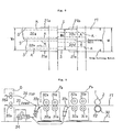
- Fig. 1 (a) is a cross-section front view of one preferred embodiment of a rotary shear according to the present invention;
- Fig. 1 (b) is a vertical cross-section view taken along line E-E in Fig. 1 (a) as viewed in the direction of arrows.
- Fig. 2 is a schematic view to be referred to for explaining a machining condition of a corrugated cardboard sheet;
- Fig. 3 is a schematic view to be referred to for explaining disadvantages of a rotary shear of the heretofore known type;
- Fig. 4(a) is a cross-section front view of a rotary shear in the prior art;
- Fig. 4(b) is a cross-section view taken along line F-F in Fig. 4(a) as viewed in the direction of arrows;
- Fig. 5 is a perspective view of an anvil cylinder in the prior art;
- Fig. 6 is a developed view of an outer circumferential surface of the same anvil cylinder;
- Fig. 7 is a schematic view to be referred to for explaining a machining condition of a corrugated cardboard sheet as depicted at the position corresponding to Fig. 6;
- Fig. 8 is a schematic view showing a scoring and cutting condition on a corrugated cardboard sheet; and
- Fig. 9 is a schematic view showing a machining process of a corrugated cardboard sheet and a traveling route of a corrugated cardboard sheet.
- Now the present invention will be described in more detail in connection to one preferred embodiment illustrated in Figs. 1 and 2. At first, a construction and an operation of a rotary shear according to one preferred embodiment of the invention will be explained with reference to Figs. 1 and 2.
- As shown in Fig. 1, a
knife cylinder 2 having aknife 1 fixedly secured thereto has its opposite ends pivotably supported fromframes bearings clutch brake 5. In addition, to the same shaft 6 is mounted apulley 7, and thispulley 7 is coupled to apulley 10 fixedly secured to a line shaft not shown or ashaft 8 of amotor 9 serving as an independent drive unit by means of anendless synchronizing belt 11 wound therearound. On the other hand, an endlesselastic body belt 12 is mounted as wound around a plurality ofrolls 14 disposed in parallel to the above-mentionedknife cylinder 2 and having the opposite ends of their shafts pivotably supported from theframes bearings 13a and 13b, respectively. The width of theelastic body belt 12 is made equal to or somewhat broader than theknife 1 on theknife cylinder 2, and thebelt 12 is constructed so as to be able to travel at a predetermined speed (a traveling speed of the corrugated cardboard web 17) by meshing agear 15 fixedly secured to one end of the shaft of theroll 14 with agear 16 mounted to the above-described line shaft or theshaft 8 of the drivingmotor 9. In these figures,reference numeral 18 designated pressing means, in which respective sections divided along the widthwise direction of thecorrugated cardboard web 17 can be individually raised or lowered by an expansion/contraction operation ofcylinders 19 such as hydraulic cylinders fixedly secured to the bottom surfaces of the sections. - Now explaining the operation, as initial setting of the rotary shear, by way of example, as illustrated in Fig. 2, in correspondence to slots in the widthwise direction of the corrugated cardboard web which become necessary as a result of displacement of the position of the upper-lower separating slitting slot in the traveling direction of the sheet according to order change,
predetermined cylinders 19 are projected (raised) for setting, thereby the sections of the pressing means 18 fixedly secured to the cylinder heads are raised and brought into slide contact with the underside of the travelingelastic body belt 12. It is to be noted that the sections of the pressing means 18 at the location where the cutting slot is not necessitated are held in a stand-by state at the lowered position. - Next, if the electromagnetic
clutch brake 5 is operated to connected so as to match the phase of theknife 1 with respect to the travelingcorrugated cardboard web 17, slots having predetermined lengths can be machined at desired positions. More particularly, to thecorrugated cardboard web 17 traveling between theelastic body belt 12 and theknife cylinder 2, acts a pinching and cutting force of theknife 1 only at to the portion (width portion) where the pressing means 18 has been raised and set, but at the portion where the pressing means 18 is set at the lowered position, a cutting force would not act due to deformation (escape) of theelastic body belt 12. Accordingly, thecorrugated cardboard web 17 is held in a state where slots in the widthwise direction are formed only at necessary portions, and it would be conveyed to the downstream stage as continuouscorrugated cardboard sheets 20 as a whole. It is to be noted that if all thecylinders 19 corresponding to the width of thecorrugated cardboard web 17 are actuated so as to press and all thepressing plates 18 are raised and set as shown in Fig. 1, then perfect cutting over the entire region in the widthwise direction is also possible, and the apparatus can quickly respond to an unexpectable accident such as production of unacceptable paper sheets. - With regard to the control method for the
elastic body belt 12, the method illustrated in Fig. 1 (a) is of such type that theshaft 8 and theroll 14 are directly coupled via thegears belt 12 are made to always rotationally travel, but various other methods can be conceived such that thebelt 12 may be driven to travel only just before and after the time for cutting by assembling a clutch not shown between theshaft 8 and theroll 14. Also, the raising and lowering means for the pressing means 18 should not be limited to the illustratedcylinders 19. - As will be apparent from the above description of the preferred embodiment, since the present invention has structural and functional features as described above, the slitting slots in the widthwise direction of the sheets which become necessary upon order change can be formed at arbitrary positions, and even in the case where two or more kinds of sheets having different cutting lengths are produced from a single corrugated cardboard sheet, smooth order change can be achieved even if the web is not perfectly cut over the entire region in the widthwise direction as is the case with the prior art. In addition, owing to the fact that the new and old sheets are not separated, jam-up in the next stage which may possibly occur upon highspeed order change or upon order change for a fragile sheet, can be eliminated, and also zig-zag traveling of the trailing end of the old sheet and the leading end of the new sheet caused by cutting over the entire width upon order change, can be eliminated. Furthermore, upon order change, a poor precision in a cut length caused by unstability (uncertainty) of traveling of a sheet can be obviated.
- While a principle of the present invention has been described above in connection to one preferred embodiment of the invention, it is intended that all matter contained in the above description and illustrated in the accompanying drawings shall be interpreted to be illustrative and not in a limiting sense.
Claims (2)
Applications Claiming Priority (2)
| Application Number | Priority Date | Filing Date | Title |
|---|---|---|---|
| JP1990078767U JPH0750194Y2 (en) | 1990-07-26 | 1990-07-26 | Rotary Sha |
| JP78767/90U | 1990-07-26 |
Publications (3)
| Publication Number | Publication Date |
|---|---|
| EP0468374A2 true EP0468374A2 (en) | 1992-01-29 |
| EP0468374A3 EP0468374A3 (en) | 1992-05-06 |
| EP0468374B1 EP0468374B1 (en) | 1994-01-05 |
Family
ID=13671055
Family Applications (1)
| Application Number | Title | Priority Date | Filing Date |
|---|---|---|---|
| EP91112070A Expired - Lifetime EP0468374B1 (en) | 1990-07-26 | 1991-07-18 | Rotary shear |
Country Status (5)
| Country | Link |
|---|---|
| US (1) | US5152205A (en) |
| EP (1) | EP0468374B1 (en) |
| JP (1) | JPH0750194Y2 (en) |
| AU (1) | AU626759B2 (en) |
| DE (1) | DE69100928T2 (en) |
Cited By (10)
| Publication number | Priority date | Publication date | Assignee | Title |
|---|---|---|---|---|
| EP0607084A1 (en) * | 1993-01-14 | 1994-07-20 | Mitsubishi Jukogyo Kabushiki Kaisha | System for changing product specifications in a corrugation machine |
| EP0999015A2 (en) * | 1998-11-04 | 2000-05-10 | Heidelberger Druckmaschinen Aktiengesellschaft | Endless cutting apparatus with an integrated blade assembly for rotary printing devices |
| EP0999040A1 (en) * | 1998-11-02 | 2000-05-10 | Mitsubishi Heavy Industries, Ltd. | Method for order changing in corrugating machines |
| US6684749B2 (en) | 2000-05-31 | 2004-02-03 | Fosber S.P.A. | Device and method for a job change in a system for the lengthwise cutting of a weblike material |
| EP1555096A2 (en) * | 2004-01-12 | 2005-07-20 | BHS Corrugated Maschinen-und Anlagenbau GmbH | Anvil for cutting web material and method for making transverse cuts in a web material using such an anvil |
| EP1652639A1 (en) * | 2004-10-26 | 2006-05-03 | BHS Corrugated Maschinen-und Anlagenbau GmbH | Method for changing the format in a corrugated board manufacturing plant |
| GB2458687A (en) * | 2008-03-28 | 2009-09-30 | True Gap Ltd | Rotary perforator or cutter having anvil belt with resilient surface |
| US8342068B2 (en) | 2004-10-12 | 2013-01-01 | Foser S.p.A. | Device for longitudinal cutting of a continuous web material, such as corrugated cardboard |
| CN109623913A (en) * | 2018-12-28 | 2019-04-16 | 常德烟草机械有限责任公司 | A kind of shearing equipment |
| CN113043657A (en) * | 2021-02-27 | 2021-06-29 | 江西华利包装科技股份有限公司 | Flute tapping machine for corrugated carton |
Families Citing this family (15)
| Publication number | Priority date | Publication date | Assignee | Title |
|---|---|---|---|---|
| DE4133760A1 (en) * | 1991-10-11 | 1993-04-15 | Bhs Bayerische Berg | METHOD AND DEVICE FOR THE PRODUCTION OF CORRUGATED CARDBOARDS WITH CHANGEABLE FORMAT |
| US6418827B1 (en) * | 1994-04-13 | 2002-07-16 | Bussey, Iii Harry | Perforating machine |
| IT1278645B1 (en) * | 1995-04-14 | 1997-11-27 | Fosber Spa | PLANT FOR CREAMING AND CUTTING OF LAMINAR MATERIAL, SUCH AS CARDBOARD OR SIMILAR |
| US5797305A (en) * | 1996-02-12 | 1998-08-25 | Moore Business Forms, Inc. | On demand cross web perforation |
| US6103171A (en) * | 1998-05-11 | 2000-08-15 | Marquip, Inc. | Method and apparatus for facilitating a gapless order change in a corrugator |
| US6117381A (en) * | 1998-05-11 | 2000-09-12 | Marquip, Inc. | Method and apparatus for providing a gapless order change in a corrugator |
| EP1031401B1 (en) | 1999-02-25 | 2003-07-02 | FOSBER S.p.A. | Apparatus for the transverse cutting of weblike material |
| DE19953908A1 (en) * | 1999-11-10 | 2001-05-17 | Sms Demag Ag | High-speed shears for cross cutting of rolled strip |
| US6756114B2 (en) * | 2001-08-21 | 2004-06-29 | Owens Corning Fiberglas Technology, Inc. | Moldable pellet based on the combination of synthetic cellulose fibers and thermoplastic polymers |
| US20030047049A1 (en) * | 2001-09-13 | 2003-03-13 | Baker John R. | Method and apparatus for collecting uncut continuous materials and producing chopped continuous materials |
| US6893520B2 (en) * | 2003-01-31 | 2005-05-17 | Marquip, Llc | Method and apparatus for synchronizing end of order cutoff for a plunge slit order change on a corrugator |
| DE10356037A1 (en) * | 2003-12-01 | 2005-07-07 | Bhs Corrugated Maschinen- Und Anlagenbau Gmbh | Corrugated cardboard web cutting device that can be used to make incomplete transverse cuts has knife and counter rollers that are controlled by a control unit so that a counter body and knife are displaced relative to each other |
| WO2008120804A1 (en) * | 2007-04-02 | 2008-10-09 | Seiji Kagawa | Linearly tearable plastic film, method and device for producing the same and |
| JP6238291B2 (en) * | 2014-02-10 | 2017-11-29 | 株式会社Isowa | Slitter control device |
| CN116373029B (en) * | 2023-06-07 | 2023-10-03 | 成都飞机工业(集团)有限责任公司 | Automatic chip removal ultrasonic jack device |
Citations (4)
| Publication number | Priority date | Publication date | Assignee | Title |
|---|---|---|---|---|
| GB1014592A (en) * | 1963-02-06 | 1965-12-31 | Fibreglass Ltd | Apparatus for perforating fibrous tissue |
| US3522762A (en) * | 1968-08-12 | 1970-08-04 | Louis E Sauer | Multiple anvil structure for rotary die cutting |
| FR2414986A1 (en) * | 1978-01-23 | 1979-08-17 | Tech Bois Centre | PROCESS AND DEVICE FOR CUTTING, CONTINUOUSLY AND ROTATING, A SHEET TRANSVERSALLY IN ITS SCROLLING DIRECTION |
| GB2103139A (en) * | 1981-07-30 | 1983-02-16 | Maulen Leonard V D | Cutting apparatus |
Family Cites Families (6)
| Publication number | Priority date | Publication date | Assignee | Title |
|---|---|---|---|---|
| US2369253A (en) * | 1943-06-14 | 1945-02-13 | Thomas R Robinson | Clipper for sheet material |
| US2733766A (en) * | 1950-11-01 | 1956-02-07 | Bias cutter | |
| US3491632A (en) * | 1968-05-02 | 1970-01-27 | Dovey Mfg Co | Attachment for rotary cardboard cutting machine |
| US4183271A (en) * | 1978-03-31 | 1980-01-15 | Merrill David Martin | Rotary web shearing machine |
| US4372184A (en) * | 1981-02-25 | 1983-02-08 | J. R. Simplot Company | Cutting assembly |
| US4691606A (en) * | 1986-08-01 | 1987-09-08 | The Mead Corporation | Web perforating apparatus |
-
1990
- 1990-07-26 JP JP1990078767U patent/JPH0750194Y2/en not_active Expired - Lifetime
-
1991
- 1991-07-18 DE DE91112070T patent/DE69100928T2/en not_active Expired - Fee Related
- 1991-07-18 EP EP91112070A patent/EP0468374B1/en not_active Expired - Lifetime
- 1991-07-22 AU AU81256/91A patent/AU626759B2/en not_active Ceased
- 1991-07-25 US US07/735,916 patent/US5152205A/en not_active Expired - Fee Related
Patent Citations (4)
| Publication number | Priority date | Publication date | Assignee | Title |
|---|---|---|---|---|
| GB1014592A (en) * | 1963-02-06 | 1965-12-31 | Fibreglass Ltd | Apparatus for perforating fibrous tissue |
| US3522762A (en) * | 1968-08-12 | 1970-08-04 | Louis E Sauer | Multiple anvil structure for rotary die cutting |
| FR2414986A1 (en) * | 1978-01-23 | 1979-08-17 | Tech Bois Centre | PROCESS AND DEVICE FOR CUTTING, CONTINUOUSLY AND ROTATING, A SHEET TRANSVERSALLY IN ITS SCROLLING DIRECTION |
| GB2103139A (en) * | 1981-07-30 | 1983-02-16 | Maulen Leonard V D | Cutting apparatus |
Cited By (17)
| Publication number | Priority date | Publication date | Assignee | Title |
|---|---|---|---|---|
| EP0607084A1 (en) * | 1993-01-14 | 1994-07-20 | Mitsubishi Jukogyo Kabushiki Kaisha | System for changing product specifications in a corrugation machine |
| US5496431A (en) * | 1993-01-14 | 1996-03-05 | Mitsubishi Jukogyo Kabushiki Kaisha | Method and system for changing product specifications in a corrugation machine |
| EP0999040A1 (en) * | 1998-11-02 | 2000-05-10 | Mitsubishi Heavy Industries, Ltd. | Method for order changing in corrugating machines |
| US6568304B2 (en) | 1998-11-02 | 2003-05-27 | Mitsubishi Heavy Industries, Ltd. | Method for order changing in corrugating machines |
| EP0999015A2 (en) * | 1998-11-04 | 2000-05-10 | Heidelberger Druckmaschinen Aktiengesellschaft | Endless cutting apparatus with an integrated blade assembly for rotary printing devices |
| EP0999015A3 (en) * | 1998-11-04 | 2002-08-07 | Heidelberger Druckmaschinen Aktiengesellschaft | Endless cutting apparatus with an integrated blade assembly for rotary printing devices |
| US6684749B2 (en) | 2000-05-31 | 2004-02-03 | Fosber S.P.A. | Device and method for a job change in a system for the lengthwise cutting of a weblike material |
| EP1555096A3 (en) * | 2004-01-12 | 2005-10-26 | BHS Corrugated Maschinen-und Anlagenbau GmbH | Anvil for cutting web material and method for making transverse cuts in a web material using such an anvil |
| EP1555096A2 (en) * | 2004-01-12 | 2005-07-20 | BHS Corrugated Maschinen-und Anlagenbau GmbH | Anvil for cutting web material and method for making transverse cuts in a web material using such an anvil |
| US8342068B2 (en) | 2004-10-12 | 2013-01-01 | Foser S.p.A. | Device for longitudinal cutting of a continuous web material, such as corrugated cardboard |
| EP1652639A1 (en) * | 2004-10-26 | 2006-05-03 | BHS Corrugated Maschinen-und Anlagenbau GmbH | Method for changing the format in a corrugated board manufacturing plant |
| US7367251B2 (en) | 2004-10-26 | 2008-05-06 | Bhs Corrugated Maschinen-Und Anlagenbau Gmbh | Format change in a corrugating plant |
| CN1781700B (en) * | 2004-10-26 | 2010-08-18 | Bhs波纹机械和设备制造有限公司 | Format change in a corrugated board manufacture device |
| GB2458687A (en) * | 2008-03-28 | 2009-09-30 | True Gap Ltd | Rotary perforator or cutter having anvil belt with resilient surface |
| CN109623913A (en) * | 2018-12-28 | 2019-04-16 | 常德烟草机械有限责任公司 | A kind of shearing equipment |
| CN113043657A (en) * | 2021-02-27 | 2021-06-29 | 江西华利包装科技股份有限公司 | Flute tapping machine for corrugated carton |
| CN113043657B (en) * | 2021-02-27 | 2022-07-22 | 江西华利包装科技股份有限公司 | Flute tapping machine for corrugated carton |
Also Published As
| Publication number | Publication date |
|---|---|
| AU8125691A (en) | 1992-01-30 |
| JPH0750194Y2 (en) | 1995-11-15 |
| EP0468374B1 (en) | 1994-01-05 |
| JPH0437328U (en) | 1992-03-30 |
| DE69100928D1 (en) | 1994-02-17 |
| AU626759B2 (en) | 1992-08-06 |
| DE69100928T2 (en) | 1994-04-28 |
| EP0468374A3 (en) | 1992-05-06 |
| US5152205A (en) | 1992-10-06 |
Similar Documents
| Publication | Publication Date | Title |
|---|---|---|
| EP0468374B1 (en) | Rotary shear | |
| EP0534177B1 (en) | Rotary shear | |
| EP0607084A1 (en) | System for changing product specifications in a corrugation machine | |
| EP0894583B1 (en) | Slitter/scorer machine with independent slitting tools and corresponding format changeover method | |
| JP4718981B2 (en) | Corrugating machine and production management device used therefor | |
| US5393294A (en) | Method and apparatus for producing sheets of corrugated cardboard with a variable format | |
| EP0449006A2 (en) | Web severing apparatus and method | |
| EP3360639B1 (en) | Method for manufacturing paper, card, cardboard or corrugated board cuts and device | |
| US5740709A (en) | Two stage continuous web cutting system and method | |
| US5133235A (en) | Skip-scorer, skip perforator for use with printing press systems | |
| RU2095250C1 (en) | Device for producing multilayer hose of paper stripes | |
| EP0458340A2 (en) | Slitterscorer | |
| US6010122A (en) | Method and apparatus for producing high page count signatures | |
| JPS6142703B2 (en) | ||
| JP2000135696A (en) | Order change method in corrugating machine | |
| US5595101A (en) | Method and apparatus for making splice indicating holes through photographic paper | |
| US11020929B2 (en) | Corrugated board web cutting device and corrugated board manufacturing device | |
| US6117381A (en) | Method and apparatus for providing a gapless order change in a corrugator | |
| JP7466320B2 (en) | Slotter head, slotter device and box making machine | |
| US6669617B1 (en) | Paper web folding and cutting apparatus | |
| EP0065014A1 (en) | Continuous corrugated fiberboard sheet specification altering apparatus | |
| JPH0976460A (en) | Paper cutting device in folding device for form printing machine | |
| JPH05193026A (en) | Slitter scorer | |
| JP2706332B2 (en) | Rotary drum type cutting device | |
| JPH0569390A (en) | Rotary drum type cutting device |
Legal Events
| Date | Code | Title | Description |
|---|---|---|---|
| PUAI | Public reference made under article 153(3) epc to a published international application that has entered the european phase |
Free format text: ORIGINAL CODE: 0009012 |
|
| 17P | Request for examination filed |
Effective date: 19910814 |
|
| AK | Designated contracting states |
Kind code of ref document: A2 Designated state(s): CH DE FR GB IT LI NL |
|
| PUAL | Search report despatched |
Free format text: ORIGINAL CODE: 0009013 |
|
| AK | Designated contracting states |
Kind code of ref document: A3 Designated state(s): CH DE FR GB IT LI NL |
|
| 17Q | First examination report despatched |
Effective date: 19930519 |
|
| GRAA | (expected) grant |
Free format text: ORIGINAL CODE: 0009210 |
|
| AK | Designated contracting states |
Kind code of ref document: B1 Designated state(s): CH DE FR GB IT LI NL |
|
| ET | Fr: translation filed | ||
| REF | Corresponds to: |
Ref document number: 69100928 Country of ref document: DE Date of ref document: 19940217 |
|
| ITF | It: translation for a ep patent filed |
Owner name: FUMERO BREVETTI S.N.C. |
|
| PGFP | Annual fee paid to national office [announced via postgrant information from national office to epo] |
Ref country code: FR Payment date: 19940711 Year of fee payment: 4 |
|
| PGFP | Annual fee paid to national office [announced via postgrant information from national office to epo] |
Ref country code: NL Payment date: 19940731 Year of fee payment: 4 |
|
| PLBE | No opposition filed within time limit |
Free format text: ORIGINAL CODE: 0009261 |
|
| STAA | Information on the status of an ep patent application or granted ep patent |
Free format text: STATUS: NO OPPOSITION FILED WITHIN TIME LIMIT |
|
| 26N | No opposition filed | ||
| PG25 | Lapsed in a contracting state [announced via postgrant information from national office to epo] |
Ref country code: GB Effective date: 19950718 |
|
| PG25 | Lapsed in a contracting state [announced via postgrant information from national office to epo] |
Ref country code: NL Effective date: 19960201 |
|
| GBPC | Gb: european patent ceased through non-payment of renewal fee |
Effective date: 19950718 |
|
| NLV4 | Nl: lapsed or anulled due to non-payment of the annual fee |
Effective date: 19960201 |
|
| PG25 | Lapsed in a contracting state [announced via postgrant information from national office to epo] |
Ref country code: FR Effective date: 19960430 |
|
| REG | Reference to a national code |
Ref country code: FR Ref legal event code: ST |
|
| REG | Reference to a national code |
Ref country code: FR Ref legal event code: ST |
|
| REG | Reference to a national code |
Ref country code: FR Ref legal event code: ST |
|
| PGFP | Annual fee paid to national office [announced via postgrant information from national office to epo] |
Ref country code: DE Payment date: 19960726 Year of fee payment: 6 |
|
| PGFP | Annual fee paid to national office [announced via postgrant information from national office to epo] |
Ref country code: CH Payment date: 19960805 Year of fee payment: 6 |
|
| PG25 | Lapsed in a contracting state [announced via postgrant information from national office to epo] |
Ref country code: LI Free format text: LAPSE BECAUSE OF NON-PAYMENT OF DUE FEES Effective date: 19970731 Ref country code: CH Free format text: LAPSE BECAUSE OF NON-PAYMENT OF DUE FEES Effective date: 19970731 |
|
| REG | Reference to a national code |
Ref country code: CH Ref legal event code: PL |
|
| PG25 | Lapsed in a contracting state [announced via postgrant information from national office to epo] |
Ref country code: DE Free format text: LAPSE BECAUSE OF NON-PAYMENT OF DUE FEES Effective date: 19980401 |
|
| PG25 | Lapsed in a contracting state [announced via postgrant information from national office to epo] |
Ref country code: IT Free format text: LAPSE BECAUSE OF NON-PAYMENT OF DUE FEES Effective date: 20050718 |