EP0469797A1 - Anaesthetic vaporiser - Google Patents
Anaesthetic vaporiser Download PDFInfo
- Publication number
- EP0469797A1 EP0469797A1 EP91306823A EP91306823A EP0469797A1 EP 0469797 A1 EP0469797 A1 EP 0469797A1 EP 91306823 A EP91306823 A EP 91306823A EP 91306823 A EP91306823 A EP 91306823A EP 0469797 A1 EP0469797 A1 EP 0469797A1
- Authority
- EP
- European Patent Office
- Prior art keywords
- vaporiser
- pressure
- passageway
- passage
- agent
- Prior art date
- Legal status (The legal status is an assumption and is not a legal conclusion. Google has not performed a legal analysis and makes no representation as to the accuracy of the status listed.)
- Granted
Links
Images


Classifications
-
- A—HUMAN NECESSITIES
- A61—MEDICAL OR VETERINARY SCIENCE; HYGIENE
- A61M—DEVICES FOR INTRODUCING MEDIA INTO, OR ONTO, THE BODY; DEVICES FOR TRANSDUCING BODY MEDIA OR FOR TAKING MEDIA FROM THE BODY; DEVICES FOR PRODUCING OR ENDING SLEEP OR STUPOR
- A61M16/00—Devices for influencing the respiratory system of patients by gas treatment, e.g. mouth-to-mouth respiration; Tracheal tubes
- A61M16/10—Preparation of respiratory gases or vapours
- A61M16/14—Preparation of respiratory gases or vapours by mixing different fluids, one of them being in a liquid phase
- A61M16/18—Vaporising devices for anaesthetic preparations
-
- G—PHYSICS
- G05—CONTROLLING; REGULATING
- G05D—SYSTEMS FOR CONTROLLING OR REGULATING NON-ELECTRIC VARIABLES
- G05D11/00—Control of flow ratio
- G05D11/02—Controlling ratio of two or more flows of fluid or fluent material
- G05D11/13—Controlling ratio of two or more flows of fluid or fluent material characterised by the use of electric means
- G05D11/131—Controlling ratio of two or more flows of fluid or fluent material characterised by the use of electric means by measuring the values related to the quantity of the individual components
- G05D11/132—Controlling ratio of two or more flows of fluid or fluent material characterised by the use of electric means by measuring the values related to the quantity of the individual components by controlling the flow of the individual components
Definitions
- the present invention relates to an anaesthetic vaporiser.
- An anaesthetic vaporiser of the by-pass type is disclosed in GB-1224478.
- a carrier gas such as oxygen, air or nitrous oxide is initially divided on entry to the vaporiser between a first stream which is directed towards the sump or vaporising chamber of the vaporiser to entrain vapour from a volatile liquid anaesthetic agent contained therein, and a second by-pass stream, the first and second stream subsequently recombining prior to leaving the vaporiser for delivery to a patient.
- the rate at which the agent is supplied to the patient is affected by, amongst other things, the rate of flow of gas in the first stream.
- This known vaporiser has been used successfully for a considerable period of time for delivering anaesthetic agents such as halothane, trichloroethylene and ether derivatives including enlfurane, fluoroxene, methoxyflurane and isoflurane.
- anaesthetic agents such as halothane, trichloroethylene and ether derivatives including enlfurane, fluoroxene, methoxyflurane and isoflurane.
- Such anaesthetic agents generally have a boiling point at normal atmospheric pressure well in excess of 40°C.
- a new anaesthetic agent, 2-(difluoromethoxy)-1,1,1,2-tetrafluoroethane has been developed which has a boiling point at normal atmospheric pressure of about 20 to 25°C.
- This physical characteristic makes vaporisers of the type disclosed in GB-1224478 unsuitable for delivering 2-(difluoromethoxy)-1,1,1,2-tetrafluoroethane to a patient, since the boiling point is approximately in the middle of the normal operating temperature range of such a vaporiser, which is generally about 15 to 35°C.
- the present invention provides an anaesthetic vaporiser which can be used to deliver an accurately controlled quantity of an anaesthetic agent to a patient dependent on the vapour pressure of the agent.
- an anaesthetic vaporiser which comprises:
- the vaporiser of the present invention will generally include a first restrictor in the passage between the inlet and the outlet, and a second restrictor in the passageway between the flow control valve and the outlet.
- One of these restrictors, generally the second restrictor will be adjustable. This can allow the concentration of the anaesthetic agent in the carrier gas, and hence the quantity of anaesthetic agent supplied to the patient, to be adjusted according to requirements.
- the restrictors will generally be laminar flow restrictors so that turbulence in the passage, over a range of pressures, is minimised.
- the vaporiser of the present invention has the significant advantage that the quantity of the anaesthetic agent supplied to a patient is very significantly less dependent on the vapour pressure of the agent. This allows the vaporiser of the present invention to be used to deliver an anaesthetic agent to a patient, which has a boiling point in the region of the operating temperature range of the vaporiser.
- An example of such an anaesthetic agent is 2-(difluoromethoxy)-1,1,1,2-tetrafluoethane.
- the vaporiser of the invention may also be used for delivery of anaesthetic agents whose boiling point is renoved from the normal operating temperature range of the vaporiser, this flexibility being a particular advantage of the vaporiser.
- the pressure difference monitoring means may comprise, for example, a differential pressure transducer.
- a differential pressure transducer may comprise two chambers which are seperated by a flexible membrane, the pressure difference being measured across the membrane.
- the pressure difference monitoring means might comprise a differential pressure switch.
- the vaporiser may include valves to control the flow of carrier gas or of anaesthetic agent or both in the event of failure of a component of the vaporiser.
- a valve may be provided to prevent flow of anaesthetic agent from the vaporising chamber. Such a valve will be opened in the normal operating condition of the vaporiser.
- a passage may be provided through which carrier gas or anaesthetic agent or both might flow past the pressure difference monitoring means, flow of fluid through the said passage being controlled by a valve. Under normal operating conditions of the vaporiser, such a valve will be closed. However, in the event of failure of a component of the equipment it can be useful to open such a valve to provide a relief passage for flow of the gas or agent, as required.
- the vaporiser includes a safety control device by which safety valves are operated. They may be operated in response to, for example, the detection of a low anaesthetic agent level in the vaporising chamber, an abnormal pressure in the passage or in the passageway or both, an abnormal temperature especially in the vaporising chamber or the passageway, a power failure, abnormal movement or positioning (for example tilting), and so on. In such failure or otherwise abnormal operating conditions, a valve controlling flow of anaesthetic agent out of the vaporising chamber will generally be closed.
- the safety control device is preferably connected to a manually variable restrictor positioned in the passageway between the flow control valve and the outlet, in such a way that addressing the condition detected by the control device is possible only after the variable restrictor has been set to the position at which flow of the anaesthetic agent is at zero.
- the vaporiser may include means for controlling the temperature of drug contained within the vaporising chamber.
- this might be a source of heat from which heat can be supplied to cause vaporisation of the agent.
- the temperature of the anaesthetic agent within the vaporising chamber can be maintained at a desired level relative to its boiling point, thereby minimising variations in vapour pressure with the surrounding temperature encountered by the vaporiser.
- This has the particular advantage of making it possible to use the vaporiser of the invention to deliver anaesthetic agents whose boiling points are significantly above normal ambient temperatures.
- the vaporiser of the invention may be provided with means for monitoring the vapour pressure of the anaesthetic agent so that the temperature of the liquid agent can be adjusted to maintain its vapour pressure at a predetermined level.
- cooling means may be provided associated with the vaporising chamber, again to maintain the temperature of anaesthetic agent within the chamber at a predetermined level relative to its boiling point, or to maintain the vapour pressure of the agent at a predetermined level.
- a source of heat may be provided in the passageway between the vaporising chamber and the outlet, in order to minimise condensation of anaesthetic agent during flow through the passageway.
- the vaporiser of the invention includes means by which leaks, for example, in the passage or the passageway, can be detected.
- leaks are detected by monitoring the way in which pressure within one or more components of the vaporiser changes with time.
- the vaporiser may include means for applying a pressure difference between carrier gas in the passage and anaesthetic vapour in the passageway.
- a piston may be included by which the pressure of the carrier gas wall of the anaesthetic agent may be increased ( or decreased).
- the subsequent change in the pressure difference between the carrier gas and the anaesthetic agent can then be monitored: if there is a leak in a component of the vaporiser, this will be apparent from the way in which the pressure difference changes with time. It will generally be desirable for the change in pressure introduced by the piston to be measured accurately. This can be achieved, for example, by operating the piston pneumatically or electrically.
- Leaks within the vaporiser, especially within the pressure difference monitoring means can be detected by isolating the pressure difference monitoring means from the carrier gas supply or form the vaporising chamber, and monitoring the change in pressure across the monitoring means.
- the vaporiser may be provided with one or more valves to allow it to be isolated from one or each of the carrier gas and the anaesthetic agent, and a vent associated with the or each such valve to allow pressure within the monitoring means to drop.
- two such valves with associated vents are provided, to allow leaks in the nonitoring means and in each arm of the flow system to be detected.
- the vaporiser enables the pressure difference monitoring means to be calibrated, to ensure that a zero pressure difference is accurately measured.
- the vaporiser may include a passageway by which the pressure difference monitoring means can be connected to a single presssure source, for example to atmospheric pressure or to the carrier gas pressure or to the anaesthetic agent pressure.
- the vaporiser may include a port by which the pressure difference nonitoring means can be connected to a single pressure source.
- the port may be one which is provided for connection of the pressure difference monitoring means to the carrier gas pressure or to the anaesthetic agent pressure, so that the connection of the monitoring means to a single pressure source simply involves disconnectio from the carrier gas and the anaesthetic agent.
- the calibration of the pressure difference monitoring means may be determined alternatively by providing more than one pressure difference monitoring means, and comparing the pressure difference monitored by the respective monitoring means. In the event that the readings from the monitoring means differ, recalibration of one or each of the monitoring means is likely to be appropriate.
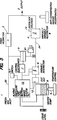
- Figure 1 shows an anaesthetic vaporiser which has an inlet 1 for carrier gas and an outlet 2 for a controlled mixture of carrier gas and gaseous anaesthetic agent. Extending between the inlet 1 and the outlet 2 is a passage 20 in which is located a fixed laminar flow restrictor 3. The restrictor 3 exhibits laminar flow characteristics over its operating range.
- a second passage 24 extends from a vaporising chamber 8 containing liquid anaesthetic agent such as 2-(difluoromethoxy)-1,1,1,2,-tetrafluoroethane to the outlet 2.
- liquid anaesthetic agent such as 2-(difluoromethoxy)-1,1,1,2,-tetrafluoroethane
- a manually variable laminar control valve 4 including an adjustable dial 44 known per se .
- an electrically operated flow control valve 6 and a vaporising chamber shut-off valve 12 which is held open during normal operation of the anaesthetic vaporiser.
- passage 20 communicates at point 22 with one chamber 30 of a differential pressure transducer 5 and with one side 26 of a transducer by-pass valve 13.
- passage 24 communicates at point 28 with a second chamber 34 of the differential pressure transducer 5 and with the other side 38 of the transducer by-pass valve 13 is held closed during normal operation of the anaesthetic vaporiser.
- the control valve 6 is electrically connected to a device 7 which receives electrical signals from the pressure transducer 5 and subject to said signals continuously controls the setting of the control valve 6.
- a heater 9 Associated with the vaporising chamber 8 is a heater 9, a temperature control system 11 and an anaesthetic agent level sensing device 10.
- a solenoid dial interlock 14 which is normally powered to allow rotation of the dial 44 of the control valve.
- a centralised alarm system 15 is provided which is electrically linked with the vaporising chamber shut-off valve 12, the transducer by-pass valve 13, the solenoid dial interlock 14, the vaporising chamber temperature control system 11, the fluid anaesthetic agent level sensing system 10 and the device 7.
- fresh carrier gas is fed to the inlet 1 of the vaporiser from a conventional flow metering bank delivering typically 0.2 to 15 litres per minute of air, oxygen and nitrous oxide in various proportions.
- the carrier gas passes along the passage 20 through the fixed restrictor 3 towards the outlet 2.
- the pressure of the carrier gas at point 22 upstream of the restrictor 3 is transmitted to the first chamber 30 of the differential pressure transducer 5.
- heat from the heater 9 will raise the temperature of the liquid anaesthetic agent in the vaporising chamber 8 and vapour will then pass through passage 24, through the shut-off valve 12 which, in normal use, is held open, through the electrically operated flow control valve 6 and the manually variable laminar control valve 4 to join with the carrier gas prior to leaving the vaporiser at the outlet 2.
- the pressure of the vapour at point 28 upstream of the control valve 4 will be communicated to the second chamber 34 of the pressure transducer 5.
- the differential pressure transducer emits an electrical signal dependent on the differential between the carrier gas pressure and the agent vapour pressure which is transmitted to the device 7 which passes a signal which controls the setting of the flow control valve 6.
- the differential pressure transducer 5, the device 7 and the electrically operated flow control valve 6 between them form an active regulator which operates to balance exactly the pressure of agent vapour at the inlet to the manually variable restrictor 4 with the pressure of fresh carrier gas at the inlet to the fixed restrictor 3.
- volume for volume ratio of vaporised agent to carrier gas depends almost wholly on the position of the manually variable valve 4 and is substantially independent of the carrier gas flow rate.
- the alarm is preferably designed so that it can only be acknowledged by rotating the manually variable restrictor dial 44 to "off" where the control dial rotation becomes interlocked and the vaporiser isolated.
- An advantage of the vaporiser shown in Figure 1 is that virtually all alarm conditions result in the inability of the device 7 to maintain a differential pressure of zero. This condition is readily monitored by the control electronics and simplifies alarm handling.
- FIG 2 there is illustrated an anaesthetic vaporiser which is a modification of the anaesthetic vaporiser referred to with reference to Figure 1.
- like reference numerals denote similar features as referred to with reference to Figure 1.
- an anaesthetic vaporiser has an inlet 1 for carrier gas and an outlet 2 for a controlled mixture of carrier gas and gaseous anaesthetic agent. Extending between the inlet 1 and the outlet 2 is a passage 20 in which is located a fixed laminar flow restrictor 3.
- a second passage 24 extends from a vaporising chamber 8 to the outlet 2. Located in passage 24 is a manually variable laminar flow control valve 4 including an adjustable dial 44.
- a differential pressure switch 50 is located between a point 22 in the passage 20 and a point 28 in the passage 24.
- a solenoid valve 52 Also located in the passage 24 is a solenoid valve 52.
- Signals from the differential pressure switch 50 are arranged to operate the solenoid valve 52.
- fresh carrier gas is fed to the inlet 1 and flows through passage 20 and fixed restrictor 3 towards the outlet 2.
- the pressure of the carrier gas at point 22 upstream of the fixed restrictor 3 is transmitted to a first side of the differential pressure switch 50.
- the pressure of the vapour at point 28 upstream of the control valve 4 will be communicated to the opposite side of the differential pressure switch 50.
- the differential pressure switch 50 will emit an electrical signal dependent on the differential between the carrier gas pressure and the agent vapour pressure which signal is transmitted to the solenoid valve 52.
- the volume between the differential pressure switch 50, the solenoid valve 52 and the variable restrictor 4 form a pressure control volume and, the differential pressure switch 50 operates the solenoid valve 52 directly opening it when the inlet pressure of carrier gas exceeds the control volume pressure and closes it when the pressures are equalised.
- the operation of the solenoid valve 52 could be arranged such that it is opened regularly, for example, every second and maintained open for a period of up to one second as required to equalise the pressures.
- Figure 3 shows a vaporiser which includes a piston 61 by which a small disturbance in the volume on the anaesthetic agent side of the circuit can be introduced.
- the piston is operated electrically, by a solenoid device (although it may operated pneumatically or manually).
- the disturbance introduced by the piston gives rise to a pressure change across the pressure difference monitoring means 5.
- the subsequent decay of the measured pressure change can provide a measure of the integrity of the pneumatic circuit in the anaesthetic agent part of the vaporiser circuit and, in particular, in the diaphragm within the differential pressure transducer which forms part of the pressure difference monitoring means.
- Figure 4 shows a vaporiser which includes two valves 63, 65 with associated vents 67, 69. Using these valves and vents, the pressure on one side of the transducer 5 can be reduced to atmospheric pressure, and the decay in the pressure difference monitored by the transducer provides a measure of the integrity of the pneumatic circuit and of the transducer diaphragm.
- Figure 5 shows an embodiment of vaporiser which includes a passageway 71 with an associated valve 73 which may be switched to allow both sides of the transducer 5 to be connected to one side (which may be the carrier gas side or the anaesthetic agent vapour side) only of the pneumatic circuit. When so connected, the output of the transducer should be zero. If it is not zero, it can be recalibrated appropriately.
- Figure 5 shows schematically the arrangement in which both sides of the transducer are connectable to the anaesthetic agent vapour side.
- the vaporiser shown in Figure 6 includes two valves 75, 77, each with associated ports 79, 81, by which each side of the transducer 5 can be exposed directly to ambient pressure. The resulting output of the transducer should then be zero, and can be adjusted appropriately if it is not.
- Figure 7 shows a vaporiser which includes two differential pressure transducers 5,5′.
- the output from the two pressure transducers can be compared and, in the event that their readings differ, an appropriate adjustment or recalibration can be made.
Abstract
Description
- The present invention relates to an anaesthetic vaporiser.
- An anaesthetic vaporiser of the by-pass type is disclosed in GB-1224478. In that vaporiser, a carrier gas such as oxygen, air or nitrous oxide is initially divided on entry to the vaporiser between a first stream which is directed towards the sump or vaporising chamber of the vaporiser to entrain vapour from a volatile liquid anaesthetic agent contained therein, and a second by-pass stream, the first and second stream subsequently recombining prior to leaving the vaporiser for delivery to a patient. The rate at which the agent is supplied to the patient is affected by, amongst other things, the rate of flow of gas in the first stream.
- This known vaporiser has been used successfully for a considerable period of time for delivering anaesthetic agents such as halothane, trichloroethylene and ether derivatives including enlfurane, fluoroxene, methoxyflurane and isoflurane. Such anaesthetic agents generally have a boiling point at normal atmospheric pressure well in excess of 40°C.
- A new anaesthetic agent, 2-(difluoromethoxy)-1,1,1,2-tetrafluoroethane, has been developed which has a boiling point at normal atmospheric pressure of about 20 to 25°C. This physical characteristic makes vaporisers of the type disclosed in GB-1224478 unsuitable for delivering 2-(difluoromethoxy)-1,1,1,2-tetrafluoroethane to a patient, since the boiling point is approximately in the middle of the normal operating temperature range of such a vaporiser, which is generally about 15 to 35°C. When the ambient temperature, and hence the vaporiser temperature, is above 25°C, heat is transferred to the low boiling point anaesthetic agent and causes an amount of the agent to vaporise until the heat lost to the latent heat of vaporisation is equal to the heat transferred to the agent.
- The present invention provides an anaesthetic vaporiser which can be used to deliver an accurately controlled quantity of an anaesthetic agent to a patient dependent on the vapour pressure of the agent.
- According, in one aspect, the invention provides an anaesthetic vaporiser which comprises:
- (a) an inlet for carrier gas;
- (b) an outlet for the carrier gas and an anaesthetic agent, for delivery to a patient;
- (c) a passage which extends between the inlet and the outlet;
- (d) a vaporising chamber for an anaesthetic agent;
- (e) a passageway which extends from the vaporising chamber to the outlet;
- (f) means for monitoring differences in pressure between the carrier gas in the passage and the agent in the passageway;
- (g) means for generating a signal corresponding to the pressure difference measured by the pressure difference monitoring means; and
- (h) a flow control valve located in the passageway for controlling the rate of flow of the agent through the passageway, the valve being controlled in response to the signal from the pressure monitoring means.
- The vaporiser of the present invention will generally include a first restrictor in the passage between the inlet and the outlet, and a second restrictor in the passageway between the flow control valve and the outlet. One of these restrictors, generally the second restrictor, will be adjustable. This can allow the concentration of the anaesthetic agent in the carrier gas, and hence the quantity of anaesthetic agent supplied to the patient, to be adjusted according to requirements.
- The restrictors will generally be laminar flow restrictors so that turbulence in the passage, over a range of pressures, is minimised.
- The vaporiser of the present invention has the significant advantage that the quantity of the anaesthetic agent supplied to a patient is very significantly less dependent on the vapour pressure of the agent. This allows the vaporiser of the present invention to be used to deliver an anaesthetic agent to a patient, which has a boiling point in the region of the operating temperature range of the vaporiser. An example of such an anaesthetic agent is 2-(difluoromethoxy)-1,1,1,2-tetrafluoethane. However, the vaporiser of the invention may also be used for delivery of anaesthetic agents whose boiling point is renoved from the normal operating temperature range of the vaporiser, this flexibility being a particular advantage of the vaporiser.
- The pressure difference monitoring means may comprise, for example, a differential pressure transducer. Such a transducer may comprise two chambers which are seperated by a flexible membrane, the pressure difference being measured across the membrane.
- The pressure difference monitoring means might comprise a differential pressure switch.
- The vaporiser may include valves to control the flow of carrier gas or of anaesthetic agent or both in the event of failure of a component of the vaporiser. For example, a valve may be provided to prevent flow of anaesthetic agent from the vaporising chamber. Such a valve will be opened in the normal operating condition of the vaporiser.
- A passage may be provided through which carrier gas or anaesthetic agent or both might flow past the pressure difference monitoring means, flow of fluid through the said passage being controlled by a valve. Under normal operating conditions of the vaporiser, such a valve will be closed. However, in the event of failure of a component of the equipment it can be useful to open such a valve to provide a relief passage for flow of the gas or agent, as required.
- Preferably, the vaporiser includes a safety control device by which safety valves are operated. They may be operated in response to, for example, the detection of a low anaesthetic agent level in the vaporising chamber, an abnormal pressure in the passage or in the passageway or both, an abnormal temperature especially in the vaporising chamber or the passageway, a power failure, abnormal movement or positioning (for example tilting), and so on. In such failure or otherwise abnormal operating conditions, a valve controlling flow of anaesthetic agent out of the vaporising chamber will generally be closed.
- The safety control device is preferably connected to a manually variable restrictor positioned in the passageway between the flow control valve and the outlet, in such a way that addressing the condition detected by the control device is possible only after the variable restrictor has been set to the position at which flow of the anaesthetic agent is at zero.
- The vaporiser may include means for controlling the temperature of drug contained within the vaporising chamber. For example, this might be a source of heat from which heat can be supplied to cause vaporisation of the agent. In this way, the temperature of the anaesthetic agent within the vaporising chamber can be maintained at a desired level relative to its boiling point, thereby minimising variations in vapour pressure with the surrounding temperature encountered by the vaporiser. This has the particular advantage of making it possible to use the vaporiser of the invention to deliver anaesthetic agents whose boiling points are significantly above normal ambient temperatures.
- The vaporiser of the invention may be provided with means for monitoring the vapour pressure of the anaesthetic agent so that the temperature of the liquid agent can be adjusted to maintain its vapour pressure at a predetermined level.
- Instead of, or in addition to, a source of heat, cooling means may be provided associated with the vaporising chamber, again to maintain the temperature of anaesthetic agent within the chamber at a predetermined level relative to its boiling point, or to maintain the vapour pressure of the agent at a predetermined level.
- A source of heat may be provided in the passageway between the vaporising chamber and the outlet, in order to minimise condensation of anaesthetic agent during flow through the passageway.
- Preferably, the vaporiser of the invention includes means by which leaks, for example, in the passage or the passageway, can be detected. Preferably, such leaks are detected by monitoring the way in which pressure within one or more components of the vaporiser changes with time. To facilitate detection of a leak in this way, the vaporiser may include means for applying a pressure difference between carrier gas in the passage and anaesthetic vapour in the passageway. For example, a piston may be included by which the pressure of the carrier gas wall of the anaesthetic agent may be increased ( or decreased). The subsequent change in the pressure difference between the carrier gas and the anaesthetic agent can then be monitored: if there is a leak in a component of the vaporiser, this will be apparent from the way in which the pressure difference changes with time. It will generally be desirable for the change in pressure introduced by the piston to be measured accurately. This can be achieved, for example, by operating the piston pneumatically or electrically.
- Leaks within the vaporiser, especially within the pressure difference monitoring means (as can occur in a diaphragm in a differential pressure transducer) can be detected by isolating the pressure difference monitoring means from the carrier gas supply or form the vaporising chamber, and monitoring the change in pressure across the monitoring means. To this end, the vaporiser may be provided with one or more valves to allow it to be isolated from one or each of the carrier gas and the anaesthetic agent, and a vent associated with the or each such valve to allow pressure within the monitoring means to drop. Preferably, two such valves with associated vents are provided, to allow leaks in the nonitoring means and in each arm of the flow system to be detected.
- Preferably, the vaporiser enables the pressure difference monitoring means to be calibrated, to ensure that a zero pressure difference is accurately measured. The vaporiser may include a passageway by which the pressure difference monitoring means can be connected to a single presssure source, for example to atmospheric pressure or to the carrier gas pressure or to the anaesthetic agent pressure. Alternatively, or in addition, the vaporiser may include a port by which the pressure difference nonitoring means can be connected to a single pressure source. The port may be one which is provided for connection of the pressure difference monitoring means to the carrier gas pressure or to the anaesthetic agent pressure, so that the connection of the monitoring means to a single pressure source simply involves disconnectio from the carrier gas and the anaesthetic agent.
- The calibration of the pressure difference monitoring means may be determined alternatively by providing more than one pressure difference monitoring means, and comparing the pressure difference monitored by the respective monitoring means. In the event that the readings from the monitoring means differ, recalibration of one or each of the monitoring means is likely to be appropriate.
- Embodiments of the invention will now be described by way of example with reference to the accompanying drawings, in which:
- Figure 1 is a schematic illustration of an anaesthetic vaporiser;
- Figure 2 is a schematic illustration of another embodiment of vaporiser;
- Figures 3 and 4 are schematic illustrations of further embodiments of vaporisers, which include leak detection components;
- Figures 5 to 7 are schematic illustrations of vaporisers which include components for calibration of the pressure difference monitoring means.
- Referring to the drawings, Figure 1 shows an anaesthetic vaporiser which has an
inlet 1 for carrier gas and anoutlet 2 for a controlled mixture of carrier gas and gaseous anaesthetic agent. Extending between theinlet 1 and theoutlet 2 is apassage 20 in which is located a fixedlaminar flow restrictor 3. Therestrictor 3 exhibits laminar flow characteristics over its operating range. - A
second passage 24 extends from a vaporisingchamber 8 containing liquid anaesthetic agent such as 2-(difluoromethoxy)-1,1,1,2,-tetrafluoroethane to theoutlet 2. Located in thepassage 24 between the vaporisingchamber 8 and theoutlet 2 is a manually variablelaminar control valve 4 including anadjustable dial 44 known per se. - Also located in the
passage 24 is an electrically operatedflow control valve 6 and a vaporising chamber shut-offvalve 12 which is held open during normal operation of the anaesthetic vaporiser. - The
passage 20 communicates atpoint 22 with onechamber 30 of adifferential pressure transducer 5 and with oneside 26 of a transducer by-pass valve 13. Similarly,passage 24 communicates atpoint 28 with asecond chamber 34 of thedifferential pressure transducer 5 and with theother side 38 of the transducer by-pass valve 13 is held closed during normal operation of the anaesthetic vaporiser. - The
control valve 6 is electrically connected to adevice 7 which receives electrical signals from thepressure transducer 5 and subject to said signals continuously controls the setting of thecontrol valve 6. - Associated with the vaporising
chamber 8 is aheater 9, atemperature control system 11 and an anaesthetic agentlevel sensing device 10. - Linked to the manually variable
laminar control valve 4 is asolenoid dial interlock 14 which is normally powered to allow rotation of thedial 44 of the control valve. - As illustrated a
centralised alarm system 15 is provided which is electrically linked with the vaporising chamber shut-offvalve 12, the transducer by-pass valve 13, thesolenoid dial interlock 14, the vaporising chambertemperature control system 11, the fluid anaesthetic agentlevel sensing system 10 and thedevice 7. - In use, fresh carrier gas is fed to the
inlet 1 of the vaporiser from a conventional flow metering bank delivering typically 0.2 to 15 litres per minute of air, oxygen and nitrous oxide in various proportions. - The carrier gas passes along the
passage 20 through the fixedrestrictor 3 towards theoutlet 2. The pressure of the carrier gas atpoint 22 upstream of therestrictor 3 is transmitted to thefirst chamber 30 of thedifferential pressure transducer 5. - As previously stated during normal operation the
transducer bypass valve 13 is closed. - Simultaneously, heat from the
heater 9 will raise the temperature of the liquid anaesthetic agent in the vaporisingchamber 8 and vapour will then pass throughpassage 24, through the shut-offvalve 12 which, in normal use, is held open, through the electrically operatedflow control valve 6 and the manually variablelaminar control valve 4 to join with the carrier gas prior to leaving the vaporiser at theoutlet 2. - The pressure of the vapour at
point 28 upstream of thecontrol valve 4 will be communicated to thesecond chamber 34 of thepressure transducer 5. The differential pressure transducer emits an electrical signal dependent on the differential between the carrier gas pressure and the agent vapour pressure which is transmitted to thedevice 7 which passes a signal which controls the setting of theflow control valve 6. Thedifferential pressure transducer 5, thedevice 7 and the electrically operatedflow control valve 6 between them form an active regulator which operates to balance exactly the pressure of agent vapour at the inlet to the manuallyvariable restrictor 4 with the pressure of fresh carrier gas at the inlet to the fixedrestrictor 3. - Thereafter, for a given carrier gas make-up and particular agent vapour the volume for volume ratio of vaporised agent to carrier gas depends almost wholly on the position of the manually
variable valve 4 and is substantially independent of the carrier gas flow rate. - All alarm conditions that arise will cause the vaporising chamber shut-off
valve 12 to close and audible/visual alarms to operate. The alarm is preferably designed so that it can only be acknowledged by rotating the manually variablerestrictor dial 44 to "off" where the control dial rotation becomes interlocked and the vaporiser isolated. - An advantage of the vaporiser shown in Figure 1 is that virtually all alarm conditions result in the inability of the
device 7 to maintain a differential pressure of zero. This condition is readily monitored by the control electronics and simplifies alarm handling. - It will be evidence that automatic zeroing of the
pressure transducer 5 is possible by the occasional operation of the transducer by-pass valve 13. - Referring now to Figure 2, there is illustrated an anaesthetic vaporiser which is a modification of the anaesthetic vaporiser referred to with reference to Figure 1. In Figure 2, like reference numerals denote similar features as referred to with reference to Figure 1.
- As shown in Figure 2, an anaesthetic vaporiser has an
inlet 1 for carrier gas and anoutlet 2 for a controlled mixture of carrier gas and gaseous anaesthetic agent. Extending between theinlet 1 and theoutlet 2 is apassage 20 in which is located a fixedlaminar flow restrictor 3. - A
second passage 24 extends from a vaporisingchamber 8 to theoutlet 2. Located inpassage 24 is a manually variable laminarflow control valve 4 including anadjustable dial 44. - A
differential pressure switch 50 is located between apoint 22 in thepassage 20 and apoint 28 in thepassage 24. - Also located in the
passage 24 is asolenoid valve 52. - Signals from the
differential pressure switch 50 are arranged to operate thesolenoid valve 52. - In use, fresh carrier gas is fed to the
inlet 1 and flows throughpassage 20 and fixedrestrictor 3 towards theoutlet 2. The pressure of the carrier gas atpoint 22 upstream of the fixedrestrictor 3 is transmitted to a first side of thedifferential pressure switch 50. - Simultaneously, heat from a heater (not shown) will raise the temperature of liquid anaesthetic agent in the vaporising
chamber 8 and vapour will then pass throughsolenoid valve 52,passage 24variable restrictor 4 to join with the carrier gas prior to leaving the vaporiser at theoutlet 2. - The pressure of the vapour at
point 28 upstream of thecontrol valve 4 will be communicated to the opposite side of thedifferential pressure switch 50. Thedifferential pressure switch 50 will emit an electrical signal dependent on the differential between the carrier gas pressure and the agent vapour pressure which signal is transmitted to thesolenoid valve 52. - The volume between the
differential pressure switch 50, thesolenoid valve 52 and thevariable restrictor 4 form a pressure control volume and, thedifferential pressure switch 50 operates thesolenoid valve 52 directly opening it when the inlet pressure of carrier gas exceeds the control volume pressure and closes it when the pressures are equalised. - The operation of the
solenoid valve 52 could be arranged such that it is opened regularly, for example, every second and maintained open for a period of up to one second as required to equalise the pressures. - It will be apparent that the modification illustrated in Figures 2 of the embodiment described with reference to Figure 1 is far simpler in that it consists of a pressure switch and solenoid valve which replace the differential pressure transducer, control electronics and flow control valve of the embodiment described with reference to Figure 1.
- Figure 3 shows a vaporiser which includes a
piston 61 by which a small disturbance in the volume on the anaesthetic agent side of the circuit can be introduced. The piston is operated electrically, by a solenoid device (although it may operated pneumatically or manually). The disturbance introduced by the piston gives rise to a pressure change across the pressure difference monitoring means 5. The subsequent decay of the measured pressure change can provide a measure of the integrity of the pneumatic circuit in the anaesthetic agent part of the vaporiser circuit and, in particular, in the diaphragm within the differential pressure transducer which forms part of the pressure difference monitoring means. - Figure 4 shows a vaporiser which includes two
valves vents transducer 5 can be reduced to atmospheric pressure, and the decay in the pressure difference monitored by the transducer provides a measure of the integrity of the pneumatic circuit and of the transducer diaphragm. - Figure 5 shows an embodiment of vaporiser which includes a passageway 71 with an associated valve 73 which may be switched to allow both sides of the
transducer 5 to be connected to one side (which may be the carrier gas side or the anaesthetic agent vapour side) only of the pneumatic circuit. When so connected, the output of the transducer should be zero. If it is not zero, it can be recalibrated appropriately. Figure 5 shows schematically the arrangement in which both sides of the transducer are connectable to the anaesthetic agent vapour side. - The vaporiser shown in Figure 6 includes two
valves ports transducer 5 can be exposed directly to ambient pressure. The resulting output of the transducer should then be zero, and can be adjusted appropriately if it is not. - Figure 7 shows a vaporiser which includes two
differential pressure transducers
Claims (18)
- An anaesthetic vaporiser which comprises:(a) an inlet (1) for carrier gas;(b) an outlet (2) for the carrier gas and an anaesthetic agent, for delivery to a patient;(c) a passage (20) which extends between the inlet and the outlet;(d) a vaporising chamber (8) for an anaesthetic agent;(e) a passageway (24) which extends from the vaporising chamber to the outlet;(f) means (5) for monitoring a differences in pressure between the carrier gas in the passage and the agent in the passageway;(g) means (15) for generating a signal corresponding to the pressure difference measured by the pressure difference monitoring means; and(h) a flow control valve (4) located in the passageway for controlling the rate of flow of the agent through the passageway, the valve being controlled in response to the signal from the pressure monitoring means.
- A vaporiser as claimed in claim 1, in which the pressure difference monitoring means (5) comprising at least one differential pressure transducer.
- A vaporiser as claimed in claim 1, in which the pressure differential monitoring means (5) comprises at least one differential pressure switch.
- A vaporiser as claimed in any one of claims 1 to 3, which includes a restrictor (3) in the passage (20).
- A vaporiser as claimed in claim 4, in which the restrictor (3) in the passage (20) is a laminar flow restrictor.
- A vaporiser as claimed in any one of claims 1 to 5, which includes a restrictor (4) in the passageway (24).
- A vaporiser as claimed in claim 6, in which the restrictor (4) in the passageway is manually adjustable.
- A vaporiser as claimed in any one of claims 1 to 7, which includes a valve (6) by which flow of anaesthetic agent from the vaporising chamber can be adjusted.
- A vaporiser as claimed in any one of claims 1 to 8, which includes a passage for by-passing the differential pressure monitoring means (15), flow of fluid through the said passage being controlled by a by-pass valve (13).
- A vaporiser as claimed in claim 9, which includes a safety control device (14), by which the or each said by-pass valve is controlled.
- A vaporiser as claimed in claim 10, which includes a manually adjustable restrictor (4) in the passageway, the safety control device (14) being connected to the said restrictor in such a way that addressing the condition detected by the control device is possible only after the variable restrictor has been set to the position at which flow of the anaesthetic agent is at zero.
- A vaporiser as claimed in any one of claims 1 to 11, which includes means (11) for controlling the temperature of the vaporising chamber (8).
- A vaporiser as claimed in any one of claims 1 to 12, which includes a source of heat (9) for anaesthetic agent in the passageway.
- A vaporiser as claimed in any one of claims 1 to 13, which includes means (61) for applying an external pressure differential between the passage (20) extending between the inlet and the outlet and the passageway (24) extending the vaporising chamber and the outlet respectively.
- A vaporiser as claimed in any one of claims 1 to 14, which includes means (63,65,67,69) for isolating pressure differential monitoring means (5) for the carrier gas pressure or the anaesthetic agent pressure.
- A vaporiser as claimed in any one of claims 1 to 15, which includes a passageway (75,77,79,81) by which both arms of the pressure differential monitoring means can be connected to a common pressure source to measure a zero pressure difference.
- A vaporiser as claimed in claim 16, in which the common pressure source is at atmospheric pressure.
- A vaporiser as claimed in any one of claims 1 to 17, which includes two pressure differential monitoring means (5, 5¹) and a device for monitoring differences between the pressure difference readings by the two monitoring means.
Applications Claiming Priority (4)
| Application Number | Priority Date | Filing Date | Title |
|---|---|---|---|
| GB9016970 | 1990-08-02 | ||
| GB909016970A GB9016970D0 (en) | 1990-08-02 | 1990-08-02 | Improvements in anaesthetic vaporisers |
| GB919109022A GB9109022D0 (en) | 1991-04-26 | 1991-04-26 | Anaesthetic vaporiser |
| GB9109022 | 1991-04-26 |
Publications (3)
| Publication Number | Publication Date |
|---|---|
| EP0469797A1 true EP0469797A1 (en) | 1992-02-05 |
| EP0469797B1 EP0469797B1 (en) | 1995-06-28 |
| EP0469797B2 EP0469797B2 (en) | 2001-12-12 |
Family
ID=26297430
Family Applications (1)
| Application Number | Title | Priority Date | Filing Date |
|---|---|---|---|
| EP91306823A Expired - Lifetime EP0469797B2 (en) | 1990-08-02 | 1991-07-25 | Anaesthetic vaporiser |
Country Status (6)
| Country | Link |
|---|---|
| US (1) | US5592934A (en) |
| EP (1) | EP0469797B2 (en) |
| JP (1) | JPH0755238B2 (en) |
| CA (1) | CA2048255C (en) |
| DE (1) | DE69110785T3 (en) |
| ES (1) | ES2073685T5 (en) |
Cited By (11)
| Publication number | Priority date | Publication date | Assignee | Title |
|---|---|---|---|---|
| FR2672806A1 (en) * | 1991-02-20 | 1992-08-21 | Draegerwerk Ag | STOP DEVICE FOR DOSING DEVICE OF AN ANESTHESIC EVAPORATOR. |
| US5649531A (en) * | 1991-11-15 | 1997-07-22 | Instrumentarium Corporation | Method and apparatus for metering an anaesthetic to a patient |
| EP0958842A1 (en) * | 1998-04-23 | 1999-11-24 | Siemens-Elema AB | Vaporiser |
| US6298845B1 (en) | 1998-09-02 | 2001-10-09 | Siemens Elema Ab | Vaporizer |
| US6443150B1 (en) | 1999-09-09 | 2002-09-03 | Siemens Elema Ab | Anaesthetic vaporizer |
| DE10347886B3 (en) * | 2003-10-10 | 2005-02-17 | Dräger Medical AG & Co. KGaA | Process for monitoring a narcotics evaporator comprises using an evaluation and control unit to control a sliding valve for selecting an operating position |
| DE102004052731B3 (en) * | 2004-10-30 | 2005-09-29 | Dräger Medical AG & Co. KGaA | Apparatus for mixing anesthetic vapor with anesthetic gas |
| GB2420080A (en) * | 2004-11-03 | 2006-05-17 | Draeger Medical Ag | Method of valve monitoring of a anaesthetic metering device |
| WO2006065202A1 (en) * | 2004-12-13 | 2006-06-22 | Hans Lambert | An anaesthetic liquid vaporizer |
| US7533872B2 (en) * | 2007-06-19 | 2009-05-19 | Oxus Co., Ltd. | Oxygen generator |
| CN110339443A (en) * | 2019-08-14 | 2019-10-18 | 北京毅安峰技术有限公司 | A kind of inhalation anesthetic vaporising device |
Families Citing this family (42)
| Publication number | Priority date | Publication date | Assignee | Title |
|---|---|---|---|---|
| SE505217C2 (en) * | 1995-10-16 | 1997-07-14 | Gibeck Ab Louis | Anesthetic drug recovery device |
| US8022095B2 (en) * | 1996-08-16 | 2011-09-20 | Pozen, Inc. | Methods of treating headaches using 5-HT agonists in combination with long-acting NSAIDs |
| AU8874898A (en) | 1997-08-30 | 1999-03-22 | Medical Industrial Equipment Limited | Anaesthetic vaporiser |
| ES2139540B1 (en) * | 1998-04-14 | 2000-09-01 | Mas Marfany Jaime | AUTOMATIC CONTROL METHOD FOR THE CONTRIBUTION OF ANESTHESICS TO A CLOSED CIRCUIT AT LOW FLOWS. |
| US6269811B1 (en) * | 1998-11-13 | 2001-08-07 | Respironics, Inc. | Pressure support system with a primary and a secondary gas flow and a method of using same |
| US6668828B1 (en) | 2000-10-16 | 2003-12-30 | Pulmonox Technologies Corporations | System and elements for managing therapeutic gas administration to a spontaneously breathing non-ventilated patient |
| US7498019B2 (en) | 2001-05-24 | 2009-03-03 | Alexza Pharmaceuticals, Inc. | Delivery of compounds for the treatment of headache through an inhalation route |
| NZ529417A (en) * | 2001-05-24 | 2006-11-30 | Alexza Pharmaceuticals Inc | Delivery of alprazolam, estazolam, midazolam or triazolam through an inhalation route |
| JP2005503425A (en) | 2001-05-24 | 2005-02-03 | アレックザ モレキュラー デリヴァリー コーポレイション | Delivery of drug ester by the prescribed inhalation route |
| US20030051728A1 (en) * | 2001-06-05 | 2003-03-20 | Lloyd Peter M. | Method and device for delivering a physiologically active compound |
| WO2002094242A1 (en) * | 2001-05-24 | 2002-11-28 | Alexza Molecular Delivery Corporation | Delivery of rizatriptan or zolmitriptan through an inhalation route |
| US7645442B2 (en) | 2001-05-24 | 2010-01-12 | Alexza Pharmaceuticals, Inc. | Rapid-heating drug delivery article and method of use |
| US7090830B2 (en) * | 2001-05-24 | 2006-08-15 | Alexza Pharmaceuticals, Inc. | Drug condensation aerosols and kits |
| US7458374B2 (en) * | 2002-05-13 | 2008-12-02 | Alexza Pharmaceuticals, Inc. | Method and apparatus for vaporizing a compound |
| US20070122353A1 (en) | 2001-05-24 | 2007-05-31 | Hale Ron L | Drug condensation aerosols and kits |
| WO2003041693A1 (en) * | 2001-11-09 | 2003-05-22 | Alexza Molecular Delivery Corporation | Delivery of diazepam through an inhalation route |
| WO2003057188A1 (en) | 2001-11-21 | 2003-07-17 | Alexza Molecular Delivery Corporation | Delivery of caffeine through an inhalation route |
| WO2003094900A1 (en) | 2002-05-13 | 2003-11-20 | Alexza Molecular Delivery Corporation | Delivery of drug amines through an inhalation route |
| US20060193788A1 (en) * | 2002-11-26 | 2006-08-31 | Hale Ron L | Acute treatment of headache with phenothiazine antipsychotics |
| CA2507158A1 (en) * | 2002-11-26 | 2004-06-10 | Alexza Molecular Delivery Corporation | Treatment of headache with antipsychotics delivered by inhalation |
| CN101371843B (en) * | 2002-11-26 | 2012-09-26 | 艾利斯达医药品公司 | Use of loxapine and amoxapine for the preparation of a medicament for the treatment of pain |
| US7550133B2 (en) * | 2002-11-26 | 2009-06-23 | Alexza Pharmaceuticals, Inc. | Respiratory drug condensation aerosols and methods of making and using them |
| US20040105818A1 (en) * | 2002-11-26 | 2004-06-03 | Alexza Molecular Delivery Corporation | Diuretic aerosols and methods of making and using them |
| US7913688B2 (en) * | 2002-11-27 | 2011-03-29 | Alexza Pharmaceuticals, Inc. | Inhalation device for producing a drug aerosol |
| ES2370395T3 (en) | 2003-05-21 | 2011-12-15 | Alexza Pharmaceuticals, Inc. | USE OF A SOLID FUEL LAYER, MANUFACTURING PROCEDURE AND CORRESPONDING HEATING UNIT. |
| US7172557B1 (en) | 2003-08-29 | 2007-02-06 | Caldyne, Inc. | Spirometer, display and method |
| US7540286B2 (en) * | 2004-06-03 | 2009-06-02 | Alexza Pharmaceuticals, Inc. | Multiple dose condensation aerosol devices and methods of forming condensation aerosols |
| CA2576961A1 (en) * | 2004-08-12 | 2006-03-02 | Alexza Pharmaceuticals, Inc. | Aerosol drug delivery device incorporating percussively activated heat packages |
| US20100006092A1 (en) * | 2004-08-12 | 2010-01-14 | Alexza Pharmaceuticals, Inc. | Aerosol Drug Delivery Device Incorporating Percussively Activated Heat Packages |
| DE102004045733B4 (en) * | 2004-09-21 | 2007-07-26 | Dräger Medical AG & Co. KG | Device for differential pressure measurement in anesthetic metering devices |
| US7438072B2 (en) * | 2005-03-02 | 2008-10-21 | Izuchukwu John I | Portable field anesthesia machine and control therefore |
| US7490607B2 (en) * | 2005-04-11 | 2009-02-17 | The General Electric Company | Anesthetic agent cassette for an anesthesia machine |
| WO2008080170A1 (en) * | 2006-12-22 | 2008-07-03 | Alexza Pharmaceuticals, Inc. | Mixed drug aerosol compositiions |
| WO2008112661A2 (en) | 2007-03-09 | 2008-09-18 | Alexza Pharmaceuticals, Inc. | Heating unit for use in a drug delivery device |
| CN101474446B (en) * | 2009-01-22 | 2011-06-15 | 北京航空航天大学 | Electric-controlled type breathing apparatus for supplying oxygen |
| US8267081B2 (en) * | 2009-02-20 | 2012-09-18 | Baxter International Inc. | Inhaled anesthetic agent therapy and delivery system |
| KR101138957B1 (en) * | 2009-12-16 | 2012-04-25 | 주식회사 멕 아이씨에스 | Electric vaporizer of anesthesia appartus |
| US9072859B2 (en) | 2011-05-31 | 2015-07-07 | Naoyuki Ishikita | Anesthetic inhalation aid device and attachment used for the same |
| CN105854146B (en) * | 2011-12-28 | 2019-10-22 | 马奎特紧急护理公司 | Carburetor arrangement for breathing apparatus |
| CN103893890B (en) * | 2012-12-27 | 2016-04-20 | 北京谊安医疗系统股份有限公司 | Anesthesia evaporator |
| US11554231B2 (en) | 2019-02-12 | 2023-01-17 | General Electric Company | Methods and systems for anesthetic agent leakage diagnostics |
| CN110496290B (en) * | 2019-09-24 | 2024-04-02 | 北京毅安峰技术有限公司 | Electronic evaporation device for inhalation anesthetic |
Citations (5)
| Publication number | Priority date | Publication date | Assignee | Title |
|---|---|---|---|---|
| DD71838A (en) * | ||||
| GB1224478A (en) * | 1967-11-29 | 1971-03-10 | Cyprane Ltd | Improvements in volatile anaesthetic vapourising apparatus |
| US4191952A (en) * | 1978-08-25 | 1980-03-04 | N.A.D., Inc. | Low oxygen flow alarm for anesthesia systems |
| EP0039932A2 (en) * | 1980-05-14 | 1981-11-18 | Drägerwerk Aktiengesellschaft | Gas proportion control device for an anaesthetising apparatus |
| US4798689A (en) * | 1987-01-24 | 1989-01-17 | Dragerwerk Aktiengesellschaft | Arrangement for controlling a vaporizer by means of pressure fluctuations |
Family Cites Families (13)
| Publication number | Priority date | Publication date | Assignee | Title |
|---|---|---|---|---|
| DE71838C (en) * | R. D. sanders in Eastbourne, Sussex, England | Innovation in apparatus for the production of metal wires or metal strips by electrolytic means | ||
| US3251361A (en) * | 1963-04-02 | 1966-05-17 | Louis M Friedman | Method of and apparatus for controlling the proporting of a vapor in a gas stream |
| US3351057A (en) * | 1964-05-28 | 1967-11-07 | Foregger Company Inc | Patient safeguarding anesthesia apparatus |
| US3741208A (en) * | 1971-02-23 | 1973-06-26 | B Jonsson | Lung ventilator |
| DE3116951C2 (en) * | 1981-04-29 | 1984-12-20 | Drägerwerk AG, 2400 Lübeck | Device for adding liquid anesthetics to the breathing gas to be supplied to the patient |
| US4442856A (en) * | 1981-08-18 | 1984-04-17 | Puritan-Bennett | Oxygen regulator and alarm system for an anesthesia machine |
| US4466433A (en) * | 1981-12-04 | 1984-08-21 | Minnesota Mining And Manufacturing Company | Overpressure relief system |
| US4474175A (en) * | 1982-07-16 | 1984-10-02 | Mechanical Service Company Inc. | Safety means for administration of anesthetic gas |
| DE3234474C2 (en) * | 1982-09-17 | 1984-11-29 | Drägerwerk AG, 2400 Lübeck | Device for adding liquid anesthetics to the breathing gas to be supplied to the patient |
| JPS6090568A (en) * | 1983-10-25 | 1985-05-21 | シチズン時計株式会社 | Flow controller for anesthetic device |
| DE3523947A1 (en) * | 1985-07-04 | 1987-01-08 | Draegerwerk Ag | NARCOSIS EVAPORATOR WITH INTERCHANGEABLE EVAPORATOR CHAMBER |
| DE3810745A1 (en) * | 1988-03-30 | 1989-10-12 | Draegerwerk Ag | GAS RATIO CONTROL DEVICE FOR NARCOSIS DEVICES |
| GB2239807A (en) * | 1990-01-09 | 1991-07-17 | Boc Group Plc | Anaesthetic vaporiser |
-
1991
- 1991-07-25 ES ES91306823T patent/ES2073685T5/en not_active Expired - Lifetime
- 1991-07-25 EP EP91306823A patent/EP0469797B2/en not_active Expired - Lifetime
- 1991-07-25 DE DE69110785T patent/DE69110785T3/en not_active Expired - Lifetime
- 1991-07-29 JP JP3188475A patent/JPH0755238B2/en not_active Expired - Fee Related
- 1991-07-31 CA CA002048255A patent/CA2048255C/en not_active Expired - Fee Related
-
1994
- 1994-06-22 US US08/264,112 patent/US5592934A/en not_active Expired - Lifetime
Patent Citations (5)
| Publication number | Priority date | Publication date | Assignee | Title |
|---|---|---|---|---|
| DD71838A (en) * | ||||
| GB1224478A (en) * | 1967-11-29 | 1971-03-10 | Cyprane Ltd | Improvements in volatile anaesthetic vapourising apparatus |
| US4191952A (en) * | 1978-08-25 | 1980-03-04 | N.A.D., Inc. | Low oxygen flow alarm for anesthesia systems |
| EP0039932A2 (en) * | 1980-05-14 | 1981-11-18 | Drägerwerk Aktiengesellschaft | Gas proportion control device for an anaesthetising apparatus |
| US4798689A (en) * | 1987-01-24 | 1989-01-17 | Dragerwerk Aktiengesellschaft | Arrangement for controlling a vaporizer by means of pressure fluctuations |
Cited By (15)
| Publication number | Priority date | Publication date | Assignee | Title |
|---|---|---|---|---|
| FR2672806A1 (en) * | 1991-02-20 | 1992-08-21 | Draegerwerk Ag | STOP DEVICE FOR DOSING DEVICE OF AN ANESTHESIC EVAPORATOR. |
| US5649531A (en) * | 1991-11-15 | 1997-07-22 | Instrumentarium Corporation | Method and apparatus for metering an anaesthetic to a patient |
| US5967141A (en) * | 1991-11-15 | 1999-10-19 | Instrumentarium Corporation | Method and apparatus for metering an anaesthetic to a patient |
| EP0958842A1 (en) * | 1998-04-23 | 1999-11-24 | Siemens-Elema AB | Vaporiser |
| US6298845B1 (en) | 1998-09-02 | 2001-10-09 | Siemens Elema Ab | Vaporizer |
| US6443150B1 (en) | 1999-09-09 | 2002-09-03 | Siemens Elema Ab | Anaesthetic vaporizer |
| DE10347886B3 (en) * | 2003-10-10 | 2005-02-17 | Dräger Medical AG & Co. KGaA | Process for monitoring a narcotics evaporator comprises using an evaluation and control unit to control a sliding valve for selecting an operating position |
| DE102004052731B3 (en) * | 2004-10-30 | 2005-09-29 | Dräger Medical AG & Co. KGaA | Apparatus for mixing anesthetic vapor with anesthetic gas |
| GB2419534A (en) * | 2004-10-30 | 2006-05-03 | Draeger Medical Ag | Device for the mixing of anaesthetic vapour with anaesthetic gas |
| GB2419534B (en) * | 2004-10-30 | 2007-05-23 | Draeger Medical Ag | Device for the mixing of anaesthetic vapour with anaesthetic gas |
| GB2420080A (en) * | 2004-11-03 | 2006-05-17 | Draeger Medical Ag | Method of valve monitoring of a anaesthetic metering device |
| GB2420080B (en) * | 2004-11-03 | 2007-03-28 | Draeger Medical Ag | Method for the valve monitoring of an anaesthetic metering device |
| WO2006065202A1 (en) * | 2004-12-13 | 2006-06-22 | Hans Lambert | An anaesthetic liquid vaporizer |
| US7533872B2 (en) * | 2007-06-19 | 2009-05-19 | Oxus Co., Ltd. | Oxygen generator |
| CN110339443A (en) * | 2019-08-14 | 2019-10-18 | 北京毅安峰技术有限公司 | A kind of inhalation anesthetic vaporising device |
Also Published As
| Publication number | Publication date |
|---|---|
| US5592934A (en) | 1997-01-14 |
| EP0469797B2 (en) | 2001-12-12 |
| ES2073685T3 (en) | 1995-08-16 |
| CA2048255A1 (en) | 1992-02-03 |
| DE69110785T3 (en) | 2002-05-23 |
| DE69110785D1 (en) | 1995-08-03 |
| JPH0755238B2 (en) | 1995-06-14 |
| ES2073685T5 (en) | 2002-03-01 |
| JPH06319802A (en) | 1994-11-22 |
| DE69110785T2 (en) | 1995-11-23 |
| CA2048255C (en) | 1996-03-12 |
| EP0469797B1 (en) | 1995-06-28 |
Similar Documents
| Publication | Publication Date | Title |
|---|---|---|
| EP0469797B2 (en) | Anaesthetic vaporiser | |
| US6164276A (en) | Accurate dose nitric oxide pulse delivery device with monitoring and alarms | |
| EP0347015B1 (en) | Medical ventilator system | |
| US4928684A (en) | Apparatus for assisting the spontaneous respiration of a patient | |
| CA2272002C (en) | High concentration no pulse delivery device | |
| US9983108B2 (en) | Apparatus, system and method for measuring resistance of an inhaler | |
| EP0659445B1 (en) | Nitric oxide delivery system | |
| US9205219B2 (en) | Gas identification system and respiratory technologies volumetrically corrected gas delivery system | |
| EP1960026B1 (en) | Gas blender with auxiliary mixed gas outlet | |
| US8752548B2 (en) | Patient ventilation system with a gas identification unit | |
| JPH0244552B2 (en) | ||
| JPH0225627B2 (en) | ||
| US4015617A (en) | Analgesic apparatus | |
| US4657008A (en) | Anesthesia and/or respirator apparatus having a moistening and/or gasification chamber | |
| EP0878208B1 (en) | Constant volume nitric oxide pulse delivery device | |
| JPH08257123A (en) | Device to identify anesthetic to be used in anesthesia system | |
| JP2795726B2 (en) | Device for measuring unknown parameters of test gas | |
| US5535737A (en) | Anesthetic vaporizers | |
| WO1999011312A1 (en) | Anaesthetic vaporiser | |
| GB1571023A (en) | Gas mixing apparatus | |
| KAreti | Anesthesia Machine or Workstation |
Legal Events
| Date | Code | Title | Description |
|---|---|---|---|
| PUAI | Public reference made under article 153(3) epc to a published international application that has entered the european phase |
Free format text: ORIGINAL CODE: 0009012 |
|
| AK | Designated contracting states |
Kind code of ref document: A1 Designated state(s): DE ES FR GB IT NL SE |
|
| 17P | Request for examination filed |
Effective date: 19920715 |
|
| 17Q | First examination report despatched |
Effective date: 19940117 |
|
| GRAA | (expected) grant |
Free format text: ORIGINAL CODE: 0009210 |
|
| ITF | It: translation for a ep patent filed |
Owner name: BARZANO' E ZANARDO MILANO S.P.A. |
|
| AK | Designated contracting states |
Kind code of ref document: B1 Designated state(s): DE ES FR GB IT NL SE |
|
| ET | Fr: translation filed | ||
| REF | Corresponds to: |
Ref document number: 69110785 Country of ref document: DE Date of ref document: 19950803 |
|
| REG | Reference to a national code |
Ref country code: ES Ref legal event code: FG2A Ref document number: 2073685 Country of ref document: ES Kind code of ref document: T3 |
|
| PLAV | Examination of admissibility of opposition |
Free format text: ORIGINAL CODE: EPIDOS OPEX |
|
| PLBQ | Unpublished change to opponent data |
Free format text: ORIGINAL CODE: EPIDOS OPPO |
|
| PLBI | Opposition filed |
Free format text: ORIGINAL CODE: 0009260 |
|
| PLAV | Examination of admissibility of opposition |
Free format text: ORIGINAL CODE: EPIDOS OPEX |
|
| PLBF | Reply of patent proprietor to notice(s) of opposition |
Free format text: ORIGINAL CODE: EPIDOS OBSO |
|
| 26 | Opposition filed |
Opponent name: INSTRUMENTARIUM CORPORATION Effective date: 19960325 |
|
| NLR1 | Nl: opposition has been filed with the epo |
Opponent name: INSTRUMENTARIUM CORPORATION |
|
| PLBF | Reply of patent proprietor to notice(s) of opposition |
Free format text: ORIGINAL CODE: EPIDOS OBSO |
|
| PLBF | Reply of patent proprietor to notice(s) of opposition |
Free format text: ORIGINAL CODE: EPIDOS OBSO |
|
| RDAH | Patent revoked |
Free format text: ORIGINAL CODE: EPIDOS REVO |
|
| APAC | Appeal dossier modified |
Free format text: ORIGINAL CODE: EPIDOS NOAPO |
|
| APAE | Appeal reference modified |
Free format text: ORIGINAL CODE: EPIDOS REFNO |
|
| APAC | Appeal dossier modified |
Free format text: ORIGINAL CODE: EPIDOS NOAPO |
|
| PGFP | Annual fee paid to national office [announced via postgrant information from national office to epo] |
Ref country code: SE Payment date: 19980622 Year of fee payment: 8 |
|
| PGFP | Annual fee paid to national office [announced via postgrant information from national office to epo] |
Ref country code: NL Payment date: 19980629 Year of fee payment: 8 |
|
| PG25 | Lapsed in a contracting state [announced via postgrant information from national office to epo] |
Ref country code: SE Free format text: LAPSE BECAUSE OF NON-PAYMENT OF DUE FEES Effective date: 19990726 |
|
| PG25 | Lapsed in a contracting state [announced via postgrant information from national office to epo] |
Ref country code: NL Free format text: LAPSE BECAUSE OF NON-PAYMENT OF DUE FEES Effective date: 20000201 |
|
| EUG | Se: european patent has lapsed |
Ref document number: 91306823.5 |
|
| NLV4 | Nl: lapsed or anulled due to non-payment of the annual fee |
Effective date: 20000201 |
|
| APAC | Appeal dossier modified |
Free format text: ORIGINAL CODE: EPIDOS NOAPO |
|
| PLAW | Interlocutory decision in opposition |
Free format text: ORIGINAL CODE: EPIDOS IDOP |
|
| RAP2 | Party data changed (patent owner data changed or rights of a patent transferred) |
Owner name: THE BOC GROUP PLC |
|
| PLAW | Interlocutory decision in opposition |
Free format text: ORIGINAL CODE: EPIDOS IDOP |
|
| RAP2 | Party data changed (patent owner data changed or rights of a patent transferred) |
Owner name: DATEX-OHMEDA INC. |
|
| PUAH | Patent maintained in amended form |
Free format text: ORIGINAL CODE: 0009272 |
|
| STAA | Information on the status of an ep patent application or granted ep patent |
Free format text: STATUS: PATENT MAINTAINED AS AMENDED |
|
| 27A | Patent maintained in amended form |
Effective date: 20011212 |
|
| AK | Designated contracting states |
Kind code of ref document: B2 Designated state(s): DE ES FR GB IT NL SE |
|
| REG | Reference to a national code |
Ref country code: GB Ref legal event code: IF02 |
|
| ET3 | Fr: translation filed ** decision concerning opposition | ||
| REG | Reference to a national code |
Ref country code: ES Ref legal event code: DC2A Kind code of ref document: T5 Effective date: 20011221 |
|
| APAH | Appeal reference modified |
Free format text: ORIGINAL CODE: EPIDOSCREFNO |
|
| PGFP | Annual fee paid to national office [announced via postgrant information from national office to epo] |
Ref country code: GB Payment date: 20060720 Year of fee payment: 16 |
|
| PGFP | Annual fee paid to national office [announced via postgrant information from national office to epo] |
Ref country code: FR Payment date: 20060724 Year of fee payment: 16 |
|
| PGFP | Annual fee paid to national office [announced via postgrant information from national office to epo] |
Ref country code: ES Payment date: 20060727 Year of fee payment: 16 |
|
| PGFP | Annual fee paid to national office [announced via postgrant information from national office to epo] |
Ref country code: IT Payment date: 20060731 Year of fee payment: 16 |
|
| GBPC | Gb: european patent ceased through non-payment of renewal fee |
Effective date: 20070725 |
|
| PG25 | Lapsed in a contracting state [announced via postgrant information from national office to epo] |
Ref country code: GB Free format text: LAPSE BECAUSE OF NON-PAYMENT OF DUE FEES Effective date: 20070725 |
|
| REG | Reference to a national code |
Ref country code: FR Ref legal event code: ST Effective date: 20080331 |
|
| PG25 | Lapsed in a contracting state [announced via postgrant information from national office to epo] |
Ref country code: FR Free format text: LAPSE BECAUSE OF NON-PAYMENT OF DUE FEES Effective date: 20070731 |
|
| REG | Reference to a national code |
Ref country code: ES Ref legal event code: FD2A Effective date: 20070726 |
|
| PG25 | Lapsed in a contracting state [announced via postgrant information from national office to epo] |
Ref country code: ES Free format text: LAPSE BECAUSE OF NON-PAYMENT OF DUE FEES Effective date: 20070726 |
|
| PG25 | Lapsed in a contracting state [announced via postgrant information from national office to epo] |
Ref country code: IT Free format text: LAPSE BECAUSE OF NON-PAYMENT OF DUE FEES Effective date: 20070725 |
|
| PGFP | Annual fee paid to national office [announced via postgrant information from national office to epo] |
Ref country code: DE Payment date: 20100728 Year of fee payment: 20 |
|
| REG | Reference to a national code |
Ref country code: DE Ref legal event code: R071 Ref document number: 69110785 Country of ref document: DE |
|
| REG | Reference to a national code |
Ref country code: DE Ref legal event code: R071 Ref document number: 69110785 Country of ref document: DE |
|
| PG25 | Lapsed in a contracting state [announced via postgrant information from national office to epo] |
Ref country code: DE Free format text: LAPSE BECAUSE OF EXPIRATION OF PROTECTION Effective date: 20110726 |