EP0474629B1 - Process for compensating a phase and amplitude cycle between a multi-phase actual and set value and circuit for implementing the process - Google Patents
Process for compensating a phase and amplitude cycle between a multi-phase actual and set value and circuit for implementing the process Download PDFInfo
- Publication number
- EP0474629B1 EP0474629B1 EP89906324A EP89906324A EP0474629B1 EP 0474629 B1 EP0474629 B1 EP 0474629B1 EP 89906324 A EP89906324 A EP 89906324A EP 89906324 A EP89906324 A EP 89906324A EP 0474629 B1 EP0474629 B1 EP 0474629B1
- Authority
- EP
- European Patent Office
- Prior art keywords
- value
- desired value
- multiphase
- phase
- actual
- Prior art date
- Legal status (The legal status is an assumption and is not a legal conclusion. Google has not performed a legal analysis and makes no representation as to the accuracy of the status listed.)
- Expired - Lifetime
Links
Images


Classifications
-
- H—ELECTRICITY
- H02—GENERATION; CONVERSION OR DISTRIBUTION OF ELECTRIC POWER
- H02P—CONTROL OR REGULATION OF ELECTRIC MOTORS, ELECTRIC GENERATORS OR DYNAMO-ELECTRIC CONVERTERS; CONTROLLING TRANSFORMERS, REACTORS OR CHOKE COILS
- H02P21/00—Arrangements or methods for the control of electric machines by vector control, e.g. by control of field orientation
- H02P21/06—Rotor flux based control involving the use of rotor position or rotor speed sensors
-
- H—ELECTRICITY
- H02—GENERATION; CONVERSION OR DISTRIBUTION OF ELECTRIC POWER
- H02M—APPARATUS FOR CONVERSION BETWEEN AC AND AC, BETWEEN AC AND DC, OR BETWEEN DC AND DC, AND FOR USE WITH MAINS OR SIMILAR POWER SUPPLY SYSTEMS; CONVERSION OF DC OR AC INPUT POWER INTO SURGE OUTPUT POWER; CONTROL OR REGULATION THEREOF
- H02M7/00—Conversion of ac power input into dc power output; Conversion of dc power input into ac power output
- H02M7/42—Conversion of dc power input into ac power output without possibility of reversal
- H02M7/44—Conversion of dc power input into ac power output without possibility of reversal by static converters
- H02M7/48—Conversion of dc power input into ac power output without possibility of reversal by static converters using discharge tubes with control electrode or semiconductor devices with control electrode
- H02M7/53—Conversion of dc power input into ac power output without possibility of reversal by static converters using discharge tubes with control electrode or semiconductor devices with control electrode using devices of a triode or transistor type requiring continuous application of a control signal
- H02M7/537—Conversion of dc power input into ac power output without possibility of reversal by static converters using discharge tubes with control electrode or semiconductor devices with control electrode using devices of a triode or transistor type requiring continuous application of a control signal using semiconductor devices only, e.g. single switched pulse inverters
- H02M7/5387—Conversion of dc power input into ac power output without possibility of reversal by static converters using discharge tubes with control electrode or semiconductor devices with control electrode using devices of a triode or transistor type requiring continuous application of a control signal using semiconductor devices only, e.g. single switched pulse inverters in a bridge configuration
- H02M7/53871—Conversion of dc power input into ac power output without possibility of reversal by static converters using discharge tubes with control electrode or semiconductor devices with control electrode using devices of a triode or transistor type requiring continuous application of a control signal using semiconductor devices only, e.g. single switched pulse inverters in a bridge configuration with automatic control of output voltage or current
- H02M7/53873—Conversion of dc power input into ac power output without possibility of reversal by static converters using discharge tubes with control electrode or semiconductor devices with control electrode using devices of a triode or transistor type requiring continuous application of a control signal using semiconductor devices only, e.g. single switched pulse inverters in a bridge configuration with automatic control of output voltage or current with digital control
Definitions
- the invention relates to a method for compensating a phase and amplitude response between a multiphase setpoint and actual value and a circuit arrangement for performing the method.
- W time function
- W (t) W sin ( ⁇ t) on a known control loop, consisting of setpoint adjuster, comparator, controller, controlled system and transmitter
- the control variable produces a phase and amplitude shift in relation to the reference variable W.
- the control variable produces a phase and amplitude shift in relation to the reference variable W.
- the phase and amplitude response is determined by the transmission behavior of the control loop. If this transmission behavior is known, the phase and amplitude response of the control loop can be compensated for by a correction device in the guide channel. If, on the other hand, the transmission behavior of the controlled system is a function of the disturbance variable or of controlled variables that are not known or cannot be measured, the phase and amplitude response of the type mentioned can only be insufficiently compensated for by means of a correction device.
- Coordinate converters are known from the textbook "Power converter for speed control of induction machines", Part III converter, by Erich Eder, 1975, pages 102 to 111 a three-phase system, a two-phase system with two orthogonal currents is formed. A current vector that rotates can be formed from these two orthogonal currents. The amount of this current vector and the circumferential angle is formed by means of a K / P converter (Cartesian / polar).
- EP 0 084 367 discloses a method and a device for controlling an AC motor, in which a current compensation circuit for the current setpoint of an induction machine or a synchronous machine is described. To compensate for the amplitude response, rectified actual phase current values and a current amount controller are used. The phase response cannot be corrected with this, since physically optimal compensation of the amplitude response is only possible if the actual current value is used.
- the invention is based on the object of a method for compensating a phase and amplitude response between a multiphase setpoint and actual value, the phase and amplitude response being generated by a response behavior-dependent transmission behavior of a controlled system, and a circuit arrangement for carrying out this invention Procedure.
- This method first determines the amount and the circumferential angle of the setpoint and actual value vector formed from the multiphase setpoint and actual value, it then being possible to determine a control difference for the amount and the phase separately.
- This absolute value difference value or this angular difference value is added to the nominal value value or to the angular nominal value of the nominal value vector.
- the compensating setpoint vector determined in this way which is available as an amount and circumferential angle, is converted into a multiphase compensating setpoint. In this way, one can compensate for the phase and amplitude response generated by the transmission behavior of the controlled system, which is dependent on a disturbance variable. A stationary control system without phase and amplitude response between setpoint and actual value is thus obtained.
- the multiphase setpoint can be fed to a setpoint correction value computer, at whose further inputs the multiphase actual value is present, and this setpoint correction value computer is electrically conductively connected to the comparators.
- a particularly advantageous embodiment of this circuit arrangement is a microcomputer, which uses a computer program to calculate the multiphase compensating setpoint from the multiphase measured actual value and the input multiphase setpoint, so that an undesired phase and amplitude response between the setpoint and actual value is compensated.
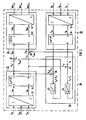
- FIG. 1 shows a multi-phase control circuit 2, which consists of several comparators 4, 6 and 8, several controllers 10, 12 and 14, an actuator 16, a controlled system 18 and a target correction value calculator 20.
- Current regulators 10, 12 and 14 are provided, for example, with a proportional or with a proportional-integral behavior, each of which generates a manipulated variable i Ry or i Sy or i Ty from a control difference i Re or i Se or i Te .
- a three-phase drive is provided as the controlled system 18, to which the actuator 16 supplies a multiphase actual value i Rx , i Sx and i Tx .
- the transmission behavior of the controlled system is also a function of a disturbance variable M z , which acts on the drive shaft.
- This compensated, multiphase setpoint i RKw , i SKw and i TKw is compared in phase with the multiphase actual value i Rx , i Sx and i Tx .
- An undesired phase and amplitude response is obtained between the multiphase setpoint i Rw , i Sw and i Tw and the multiphase actual value i Rx , i Sx and i Tx with increasing frequency of the setpoint i Rw , i Sw and i Tw .
- the frequency and the amplitude of the multiphase setpoint i Rw , i Sw and i Tw which is impressed into the controlled system 18 via the controllers 10, 12 and 14 and the actuator 16, is a function of the desired speed and the torque of the three-phase machine.
- this undesired phase and amplitude response between the multiphase setpoint and actual value i Rw , i Sw , i Tw and i Rx , i Sx , i Tx can be compensated.
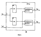
- FIG. 2 shows a block diagram of the target correction value calculator 20.
- a setpoint vector computer 26 is on the input side and an actual value vector computer 28 is on the output side a second setpoint calculator 30 is provided.
- a multiphase, in particular a three-phase, setpoint i Rw , i Sw and i Tw is fed to the setpoint vector computer 26.
- This setpoint vector computer 26 contains a coordinate converter 32 and a K / P converter 34, which are electrically connected in series.
- the coordinate converter 32 converts the three-phase system into an orthogonal system. A circuit design of this coordinate converter 32 is shown in more detail in FIG. 3.
- the actual value vector computer 28 is constructed in exactly the same way as the setpoint vector computer 26, namely with a coordinate converter 32 and a K / P converter 34.
- the multiphase, in particular three-phase, actual value i Rx , i Sx and i Tx is over two orthogonal actual values i ⁇ x and i ⁇ x in an actual value
- each block 26, 28, 30 and 36 of the target correction value computer 20 is approximately implemented by a software program, the coordinate conversions on the input and output sides preferably being implemented in hardware, since at least the multiphase actual value i Rx , i Sx and i Tx is an analog one Is worth.
- the outputs of the setpoint vector calculator 26 and the actual value vector calculator 28 are connected on the input side to a compensation circuit 36, the absolute value setpoint
- the first differential element 38 there is an absolute value difference
- an angle difference value ⁇ w ⁇ ⁇ x from which an angle control value ⁇ wxy is generated by means of a further controller 44, which is applied to a further output of the compensation circuit 36.
- a proportional-integral controller is provided as controller 42.
- An integrally acting regulator is provided as regulator 44. The more the actual value vector i x deviates in magnitude and phase from the setpoint vector i w , the greater the manipulated variable value
- the outputs of the setpoint vector computer 26 and the outputs of the compensation circuit 36 are added by means of two adders 46 and 48 in terms of amount and phase.
- This compensated setpoint vector i represented by amount and phase w K is converted by means of the second setpoint calculator 30 into a three-phase compensated setpoint i RKw , i SKw and i TKw .
- the second setpoint calculator 30 contains a P / K converter 50 (Polar / Cartesian) and a coordinate converter 52, which are electrically connected in series.
- the setpoint computer 30 has a polar-Cartesian coordinate converter 50 with which the absolute value
- FIGS. 5 and 6 show circuit designs of the P / K converter 50 and the coordinate converter 52.
- This second setpoint calculator 30 can also be implemented in software.
- a corresponding program is stored as a subroutine in the target correction value calculator 20. It would also be advantageous that only the P / K converter 50 is implemented in software and the coordinate converter 52 in hardware if the subsequent regulation is carried out digitally or analogously.
- this nominal correction value computer 20 With the aid of this nominal correction value computer 20 it is achieved that the undesired phase and amplitude response between the multiphase nominal and actual value i Rw , i Sw , i Tw and i Rx , i Sx and i Tx , caused by the transmission behavior of the controlled system 18, that of a Disturbance variable M z and the frequency of the setpoint i Rw , i Sw and i Tw is compensated for.
- FIG. 3 shows a circuit configuration of the coordinate converter 32 of the target correction value computer 20 from FIG. 2.
- This coordinate converter 32 converts a three-phase system, for example a three-phase setpoint i Rw , i Sw and i Tw or a three-phase actual value i Rx , i Sx and i Tx, into an orthogonal system, for example orthogonal setpoints i ⁇ w and i ⁇ w or orthogonal actual values i ⁇ x and i ⁇ x around.
- the axes of the two-phase system are placed so that an axis ⁇ coincides with the direction of the current i R.
- the three-phase setpoint or actual value i Rw , i Sw , i Tw or i Rx , i Sx , i Tx is used for calculation (in terms of software) or determination (in terms of hardware).
- the factors of the two equations are determined by the resistances of the individual operational amplifiers 54, 56, 58 and 60, only the two operational amplifiers 54 and 56 being used for the setpoint or actual value i ⁇ w, x .
- the operational amplifier 62 or 64 connected as an inverter cancels the phase reversal of the operational amplifiers 54 and 56 or 58 and 60.
- the orthogonal setpoints or actual values i ⁇ w , i ⁇ w or i ⁇ x , i ⁇ x are obtained at the two outputs.
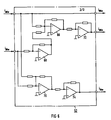
- FIG. 4 shows the K / P converter 34 as a circuit design.
- the part of the circuit with which the angle ⁇ w or ⁇ x of the setpoint or actual value vector i w or i x is determined from US Pat. No. 4,449,117.
- This circuit design is a hardware implementation of the two equations which can also be implemented in software.
- FIG. 5 shows the P / K converter 50 as a circuit design with which polar coordinates
- , ⁇ Kw are converted into Cartesian coordinates i ⁇ Kw , i ⁇ Kw . This conversion takes place according to the equations: i ⁇ Kw
- ⁇ Sin ⁇ Kw i ⁇ Kw
- each converter 32, 34, 50 and 52 can be implemented in software by a program part of a computing program.
- the coordinate converter 52 is shown as a circuit design.
- This converter 52 converts an orthogonal system i ⁇ Kw , i ⁇ Kw into a three-phase system i RKw , i SKw and i TKw .
- the circuit design represents only a hardware implementation of the three equations, only operational amplifiers 66, 68, 70, 72 and resistors being used for factor formation.
Abstract
Description
Die Erfindung bezieht sich auf ein Verfahren zur Kompensation eines Phasen- und Amplitudengangs zwischen einem mehrphasigen Soll- und Istwert und einer Schaltungsanordnung zur Durchführung des Verfahrens.The invention relates to a method for compensating a phase and amplitude response between a multiphase setpoint and actual value and a circuit arrangement for performing the method.
Wird eine Führungsgröße W beispielsweise nach einer Zeitfunktion ![]()
![]()
Der Phasen- und Amplitudengang wird bestimmt durch das Übertragungsverhalten des Regelkreises. Ist dieses Übertragungsverhalten bekannt, so kann der Phasen- und Amplitudengang des Regelkreises durch eine Korrektureinrichtung im Führungskanal kompensiert werden. Ist dagegen das Übertragungsverhalten der Regelstrecke eine Funktion der Störgröße oder von Regelgrößen, die nicht bekannt bzw. nicht meßbar sind, abhängig, so kann mittels einer Korrektureinrichtung im Führungskanal der genannten Art der Phasen- und Amplitudengang nur unzureichend kompensiert werden.The phase and amplitude response is determined by the transmission behavior of the control loop. If this transmission behavior is known, the phase and amplitude response of the control loop can be compensated for by a correction device in the guide channel. If, on the other hand, the transmission behavior of the controlled system is a function of the disturbance variable or of controlled variables that are not known or cannot be measured, the phase and amplitude response of the type mentioned can only be insufficiently compensated for by means of a correction device.
Aus dem Lehrbuch "Stromrichter zur Drehzahlsteuerung von Drehfeldmaschinen", Teil III Umrichter, von Erich Eder, 1975, Seiten 102 bis 111, sind Koordinatenwandler bekannt, mit denen aus einem Drehstromsystem ein Zweiphasensystem mit zwei orthogonalen Strömen gebildet wird. Aus diesen beiden orthogonalen Strömen läßt sich ein Stromvektor bilden, der rotiert. Der Betrag dieses Stromvektors und der umlaufende Winkel wird mittels eines K/P-Wandlers (Kartesisch/Polar) gebildet.Coordinate converters are known from the textbook "Power converter for speed control of induction machines", Part III converter, by Erich Eder, 1975, pages 102 to 111 a three-phase system, a two-phase system with two orthogonal currents is formed. A current vector that rotates can be formed from these two orthogonal currents. The amount of this current vector and the circumferential angle is formed by means of a K / P converter (Cartesian / polar).
Aus der EP 0 084 367 ist ein Verfahren und eine Vorrichtung zur Steuerung eines Wechselstrommotors bekannt, in der eine Stromkompensationsschaltung für den Stromsollwert einer Induktionsmaschine oder einer Synchronmachine beschrieben wird. Zur Kompensation des Amplitudenganges werden gleichgerichtete Phasenstromistwerte und ein Strombetragsregler verwendet. Der Phasengang kann damit nicht korrigiert werden, da eine physikalisch optimale Kompensation des Amplitudenganges nur möglich ist, wenn der Strombetragsistwert verwendet wird.
Der Erfindung liegt nun die Aufgabe zugrunde, ein Verfahren zur Kompensation eines Phasen- und Amplitudengangs zwischen einem mehrphasigen Soll- und Istwert, wobei der Phasen- und Amplitudengang durch ein von einer Störgröße abhängiges Übertragungsverhalten einer Regelstrecke erzeugt sind, und eine Schaltungsanordnung zur Durchführung dieses erfindungsgemäßen Verfahrens anzugeben.The invention is based on the object of a method for compensating a phase and amplitude response between a multiphase setpoint and actual value, the phase and amplitude response being generated by a response behavior-dependent transmission behavior of a controlled system, and a circuit arrangement for carrying out this invention Procedure.
Diese Aufgabe wird erfindungsgemäß mit den Merkmalen des Anspruchs 1 gelöst.This object is achieved with the features of claim 1.
Durch dieses Verfahren wird zunächst der Betrag und der umlaufende Winkel des aus den mehrphasigen Soll- und Istwert gebildeten Soll- und Istwertvektor bestimmt, wobei dann eine Regeldifferenz für den Betrag und die Phase getrennt ermittelt werden kann. Dieser Betragsdifferenzwert bzw. dieser Winkeldifferenzwert wird mit dem Betragssollwert bzw. mit dem Winkelsollwert des Sollwertvektors addiert. Der so ermittelte kompensierende Sollwertvektor, der als Betrag und umlaufender Winkel vorliegt, wird in einen mehrphasigen kompensierenden Sollwert gewandelt. Dadurch kann man durch das von einer Störgröße abhängige Übertragungsverhalten der Regelstrecke erzeugten Phasen- und Amplitudengang kompensieren. Somit erhält man stationär ein Regelungssystem ohne Phasen- und Amplitudengang zwischen Soll- und Istwert.This method first determines the amount and the circumferential angle of the setpoint and actual value vector formed from the multiphase setpoint and actual value, it then being possible to determine a control difference for the amount and the phase separately. This absolute value difference value or this angular difference value is added to the nominal value value or to the angular nominal value of the nominal value vector. The compensating setpoint vector determined in this way, which is available as an amount and circumferential angle, is converted into a multiphase compensating setpoint. In this way, one can compensate for the phase and amplitude response generated by the transmission behavior of the controlled system, which is dependent on a disturbance variable. A stationary control system without phase and amplitude response between setpoint and actual value is thus obtained.
Vorteilhafte Verfahrensschritte sind den Unteransprüchen 2 bis 4 zu entnehmen.Advantageous process steps can be found in
Bei einer erfindungsgemäßen Schaltungsanordnung zur Durchführung des Verfahrens mit einer Regelstrecke, der ein mehrphasiger Istwert von einem Stellglied zuführbar ist, und die mittels Vergleicher mit einem mehrphasigen Sollwert verglichen wird, dessen mehrphasige Regeldifferenz über Regler dem Stellglied zuführbar ist, ist der mehrphasige Sollwert einem Sollkorrekturwertrechner zuführbar, an dessen weiteren Eingängen der mehrphasige Istwert ansteht, und ist dieser Sollkorrekturwertrechner mit den Vergleichern elektrisch leitend verbunden.In a circuit arrangement according to the invention for carrying out the method with a controlled system, to which a multiphase actual value can be supplied by an actuator, and which by means of Comparator is compared with a multiphase setpoint whose multiphase control difference can be fed to the actuator via the controller, the multiphase setpoint can be fed to a setpoint correction value computer, at whose further inputs the multiphase actual value is present, and this setpoint correction value computer is electrically conductively connected to the comparators.
Vorteilhafte Ausgestaltungen des Sollkorrekturwertrechners sind den Unteransprüchen 6 bis 10 zu entnehmen.Advantageous refinements of the target correction value calculator can be found in subclaims 6 to 10.
Mit dieser Schaltungsanordnung ist es möglich, einen unerwünschten Phasen- und Amplitudengang zwischen dem mehrphasigen Soll- und Istwert im stationären Zustand zu kompensieren, obwohl das Übertragungsverhalten der Regelstrecke eine Funktion der Störgröße ist.With this circuit arrangement it is possible to compensate for an undesired phase and amplitude response between the multiphase setpoint and actual value in the steady state, although the transmission behavior of the controlled system is a function of the disturbance variable.
Eine besonders vorteilhafte Ausführungsform dieser Schaltungsanordnung ist ein Mikrorechner, der mittels eines Rechenprogramms aus dem mehrphasigen gemessenen Istwert und dem eingegebenen mehrphasigen Sollwert den mehrphasigen kompensierenden Sollwert berechnet, so daß ein unerwünschter Phasen- und Amplitudengang zwischen Soll- und Istwert kompensiert wird.A particularly advantageous embodiment of this circuit arrangement is a microcomputer, which uses a computer program to calculate the multiphase compensating setpoint from the multiphase measured actual value and the input multiphase setpoint, so that an undesired phase and amplitude response between the setpoint and actual value is compensated.
Zur weiteren Erläuterung der Erfindung wird auf die Zeichnung Bezug genommen, in der ein Ausführungsbeispiel der Schaltungsanordnung zur Durchführung des erfindungsgemäßen Verfahrens zur Kompensation eines Phasen- und Amplitudengangs zwischen einem mehrphasigen Soll- und Istwert schematisch veranschaulicht ist.
- Figur 1
- zeigt einen mehrphasigen Regelkreis mit einer Schaltungsanordnung zur Durchführung des erfindungsgemäßen Verfahrens, in
Figur 2- ist ein Blockschaltbild der Schaltungsanordnung zur Durchführung des erfindungsgemäßen Verfahrens nach Figur 1 dargestellt und die
Figuren 3 bis 6- veranschaulichen Schaltungsbeispiele für die einzelnen Blöcke des Blockschaltbildes der Schaltungsanordnung nach
Figur 2.
- Figure 1
- shows a multi-phase control circuit with a circuit arrangement for performing the method according to the invention, in
- Figure 2
- is a block diagram of the circuit arrangement for performing the method according to the invention shown in Figure 1 and the
- Figures 3 to 6
- illustrate circuit examples for the individual blocks of the block diagram of the circuit arrangement according to FIG. 2.
In Figur 1 ist ein mehrphasiger Regelkreis 2 dargestellt, der aus mehreren Vergleichern 4, 6 und 8, mehreren Reglern 10,12 und 14, einem Stellglied 16, einer Regelstrecke 18 und einem Sollkorrekturwertrechner 20 besteht. Als konkrete Ausführung dieses mehrphasigen Regelkreises 2 ist eine konventionelle Stromregelung für einen Drehstromantrieb mit Spannungszwischenkreisumrichter 22, der von einem Pulsweitenmodulator 24 angesteuert wird, vorgesehen. Als Regler 10, 12 und 14 sind Stromregler beispielsweise mit einem proportionalen oder mit einem proportional-integralen Verhalten vorgesehen, die jeweils aus einer Regeldifferenz iRe bzw. iSe bzw. iTe eine Stellgröße iRy bzw. iSy bzw. iTy erzeugt. Als Regelstrecke 18 ist ein Drehstromantrieb vorgesehen, dem vom Stellglied 16 ein mehrphasiger Istwert iRx, iSx und iTx zugeführt wird. Das Übertragungsverhalten der Regelstrecke ist auch eine Funktion einer Störgröße Mz, die auf der Antriebswelle einwirkt. An den ersten Eingängen des Sollkorrekturwertrechners 20, der in den Figuren 2 bis 6 noch näher erläutert wird, anstehender mehrphasiger Sollwert iRw, iSw und iTw wird mit Hilfe des mehrphasigen Istwerts iRx, iSx und iTx ein kompensierter, mehrphasiger Sollwert iRKw, iSKw und iTKw erzeugt. Dieser kompensierte, mehrphasige Sollwert iRKw, iSKw und iTKw wird mit dem mehrphasigen Istwert iRx, iSx und iTx phasenrichtig verglichen. Man erhält zwischen dem mehrphasigen Sollwert iRw, iSw und iTw und dem mehrphasigen Istwert iRx, iSx und iTx bei zunehmender Frequenz des Sollwerts iRw, iSw und iTw einen unerwünschten Phasen- und Amplitudengang. Die Frequenz und die Amplitude des mehrphasigen Sollwerts iRw, iSw und iTw, der über die Regler 10, 12 und 14 und dem Stellglied 16 in die Regelstrecke 18 eingeprägt wird, ist dabei eine Funktion der gewünschten Drehzahl und des Drehmomentes der Drehstrommaschine. Mit Hilfe des Sollkorrekturwertrechners kann dieser unerwünschte Phasen-und Amplitudengang zwischen dem mehrphasigen Soll- und Istwert iRw, iSw, iTw und iRx, iSx, iTx kompensiert werden.1 shows a
In Figur 2 ist ein Blockschaltbild des Sollkorrekturwertrechners 20 dargestellt. Eingangsseitig ist ein Sollwertvektorrechner 26 und ein Istwertvektorrechner 28 und ausgangsseitig ist ein zweiter Sollwertrechner 30 vorgesehen. Dem Sollwertvektorrechner 26 ist ein mehrphasiger, insbesondere ein dreiphasiger, Sollwert iRw, iSw und iTw zugeführt. Dieser Sollwertvektorrechner 26 enthält einen Koordinatenwandler 32 und einen K/P-Wandler 34, die elektrisch in Reihe geschaltet sind. Der Koordinatenwandler 32 wandelt das Dreiphasensystem in ein orthogonales System um. Eine Schaltungsausführung dieses Koordinatenwandlers 32 ist in Figur 3 näher dargestellt. An den Ausgängen des Koordinatenwandlers 32 erhält man zwei orthogonale Sollwerte iαw und iβw, die mittels des K/P-Wandlers 34 in einen Betragssollwert |iw| und einen umlaufenden Winkelsollwert εw des Stromwertvektors iw transformiert werden. D.h., mittels des Koordinatenwandlers 34 wird ein kartesisches Koordinatensystem in ein Polarkoordinatensystem gewandelt. Eine Schaltungsausführung dieses K/P-Wandlers 34 ist in Figur 4 näher dargestellt.FIG. 2 shows a block diagram of the target
Der Istwertvektorrechner 28 ist genauso aufgebaut, wie der Sollwertvektorrechner 26, nämlich mit einem Koordinatenwandler 32 und einem K/P-Wandler 34. Mittels dieser Wandler 32 und 34 wird der mehrphasige, insbesondere dreiphasige, Istwert iRx, iSx und iTx über zwei orthogonale Istwerte iαx und iβx in einem Betragsistwert |ix| und einen umlaufenden Winkelistwert εx des Istwertvektors ix.The actual
Die Ermittlung des Betragssollwertes |iw| mit zugehörigem umlaufenden Winkelsollwert εw des Sollwertvektors iw und des Betragsistwertes |ix| mit zugehörigem umlaufenden Winkelistwert εx des Istwertvektors ix kann hardwaremäßig, wie noch näher in den Figuren 3 und 4 erläutert werden wird, oder softwaremäßig durchgeführt werden. Bei der softwaremäßigen Ermittlung ist jeder Block 26, 28, 30 und 36 des Sollkorrekturwertrechners 20 annähernd durch ein Softwareprogramm realisiert, wobei die eingangs- und ausgangsseitigen Koordinatenwandlungen vorzugsweise hardwaremäßig realisiert werden, da wenigstens der mehrphasige Istwert iRx, iSx und iTx ein analoger Wert ist.The determination of the target amount | i w | with the associated circumferential angle setpoint ε w of the setpoint vector i w and the actual amount value | i x | With the associated circumferential actual angle value ε x of the actual value vector i x, it can be carried out by hardware, as will be explained in more detail in FIGS. 3 and 4, or by software. In the software determination, each
Die Ausgänge des Sollwertvektorrechners 26 und des Istwertvektorrechners 28 sind eingangsseitig mit einer Kompensationsschaltung 36 verbunden, wobei der Betragssollwert |iw| und der Betragsistwert |ix| mit einem ersten Differenzglied 38 und der Winkelsollwert εw und der Winkelistwert εx mit einem zweiten Differenzglied 40 verbunden ist. Am Ausgang des ersten Differenzgliedes 38 steht ein Betragsdifferenzwert |iw| - |ix| an, aus dem mittels eines Reglers 42 ein Betragsstellwert |iwxy| erzeugt wird, der am Ausgang der Kompensationsschaltung 36 ansteht. Am Ausgang des zweiten Differenziergliedes 40 steht ein Winkeldifferenzwert εw - εx an, aus dem mittels eines weiteren Reglers 44 ein Winkelstellwert εwxy erzeugt wird, der an einen weiteren Ausgang der Kompensationsschaltung 36 ansteht. Als Regler 42 ist ein proportional-integral wirkender Regler vorgesehen. Als Regler 44 ist ein integral wirkender Regler vorgesehen. Je mehr der Istwertvektor ix in Betrag und Phase vom Sollwertvektor iw abweicht, umso größer ist der Betragsstellwert |iwxy| und der Winkelstellwert εwxy an den beiden Ausgängen der Kompensationsschaltung 36.The outputs of the
Die Ausgänge des Sollwertvektorrechners 26 und die Ausgänge der Kompensationsschaltung 36 werden mittels zweier Addierer 46 und 48 betrags- und phasenmäßig addiert. Am Ausgang des Addierers 46 steht ein kompensierter Betragssollwert |iKw| und am Ausgang des Addierers 48 steht ein kompensierter Winkelsollwert εKw an. Dieser durch Betrag und Phase dargestellte kompensierte Sollwertvektor i![]()
![]()
Der zweite Sollwertrechner 30 enthält einen P/K-Wandler 50 (Polar/Kartesisch) und einen Koordinatenwandler 52, die elektrisch in Reihe geschaltet sind. Eingangsseitig weist der Sollwertrechner 30 einen polar-kartesischen Koordinatenwandler 50 auf, mit dem aus dem Betragswert |iKw| und dem Winkelwert εKw zwei orthogonale Sollwerte iαKw und iβKw erzeugt werden. Diese orthogonalen Sollwerte iαKw und iβKw werden mittels des Koordinatenwandlers 52 in einen dreiphasigen kompensierten Sollwert iRKw, iSKw und iTKw gewandelt. In den Figuren 5 und 6 sind Schaltungsausführungen des P/K-Wandlers 50 und des Koordinatenwandlers 52 dargestellt. Auch dieser zweite Sollwertrechner 30 kann softwaremäßig realisiert werden. Dabei ist ein entsprechendes Programm als ein Unterprogramm im Sollkorrekturwertrechner 20 abgespeichert. Vorteilhaft wäre auch, daß nur der P/K-Wandler 50 softwaremäßig und der Koordinatenwandler 52 hardwaremäßig realisiert werden, wenn die nachfolgende Regelung digital oder analog durchgeführt wird.The
Mit Hilfe dieses Sollkorrekturwertrechners 20 wird erreicht, daß der unerwünschte Phasen- und Amplitudengang zwischen dem mehrphasigen Soll- und Istwert iRw, iSw, iTw und iRx, iSx und iTx, verursacht vom Übertragungsverhalten der Regelstrecke 18, das von einer Störgröße Mz und der Frequenz des Sollwertes iRw, iSw und iTw abhängig ist, kompensiert wird.With the aid of this nominal
In Figur 3 ist eine Schaltungsausführung des Koordinatenwandlers 32 des Sollkorrekturwertrechners 20 der Figur 2 dargestellt. Dieser Koordinatenwandler 32 wandelt ein dreiphasiges System, beispielsweise einen dreiphasigen Sollwert iRw, iSw und iTw bzw. einen dreiphasigen Istwert iRx, iSx und iTx in ein orthogonales System, beispielsweise orthogonale Sollwerte iαw und iβw bzw. orthogonale Istwerte iαx und iβx um. Aus dem Buch "Stromrichter zur Drehzahlsteuerung von Drehfeldmaschinen", Teil III Umrichter, Seiten 102 bis 111, insbesondere Seiten 105 und 106, geht hervor, wie aus zwei Phasenströmen eines Drehstromsystems ein Zweiphasensystem mit zwei senkrechten Strömen gebildet wird. Die Achsen des Zweiphasensystems sind dabei so gelegt, daß eine Achse α mit der Richtung des Stromes iR zusammenfällt. Bei dem hier dargestellten Koordinatenwandler 32 wird der dreiphasige Sollwert bzw. Istwert iRw, iSw, iTw bzw. iRx, iSx, iTx zur Berechnung (softewaremäßig) bzw. Ermittlung (hardwaremäßig) verwendet. Gemäß folgender Gleichungen
![]()

werden die orthogonalen Soll- bzw. Istwerte iαw, iβw bzw. iαx, iβx berechnet oder durch die in der Figur 3 dargestellten Schaltung ermittelt. Durch die Widerstände der einzelnen Operationsverstärker 54, 56, 58 und 60 werden die Faktoren der beiden Gleichungen bestimmt, wobei für den Soll- bzw. Istwert iαw,x nur die beiden Operationsverstärker 54 und 56 verwendet werden. Der als Inverter geschaltete Operationsverstärker 62 bzw. 64 hebt die Phasenumkehrung der Operationsverstärker 54 und 56 bzw. 58 und 60 wieder auf. An den beiden Ausgängen erhält man die orthogonalen Soll- bzw. Istwerte iαw, iβw bzw. iαx, iβx.FIG. 3 shows a circuit configuration of the coordinate
![]()
the orthogonal setpoints or actual values i αw , i βw or i αx , i βx are calculated or determined by the circuit shown in FIG. 3. The factors of the two equations are determined by the resistances of the individual
Die Figur 4 zeigt den K/P-Wandler 34 als Schaltungsausführung. Dabei ist der Teil der Schaltung, mit dem der Winkel εw bzw. εx des Soll- bzw. Istwertvektors iw bzw. ix ermittelt wird aus der US-PS 44 49 117 bekannt. Diese Schaltungsausführung ist eine hardwaremäßige Umsetzung der beiden Gleichungen
die auch softwaremäßig umgesetzt werden können.FIG. 4 shows the K /
which can also be implemented in software.
In Figur 5 ist der P/K-Wandler 50 als Schaltungsausführung dargestellt, mit dem Polarkoordinaten |iKw|, εKw in kartesische Koordinaten iαKw, iβKw umgewandelt werden. Diese Umwandlung erfolgt gemäß Gleichungen:
![]()
![]()
FIG. 5 shows the P /
![]()
![]()
Diese Gleichungen sind hardwaremäßig umgesetzt worden, wobei bei einem Einsatz eines Mikrorechners als Sollkorrekturwertrechner 20 jeder Wandler 32, 34, 50 und 52 durch einen Programmteil eines Rechenprogramms softwaremäßig umgesetzt werden kann.These equations have been implemented in terms of hardware, and if a microcomputer is used as the target
In Figur 6 ist der Koordinatenwandler 52 als Schaltungsausführung dargestellt. Dieser Wandler 52 wandelt ein orthogonales System iαKw, iβKw in ein dreiphasiges System iRKw, iSKw und iTKw um. Dabei kann das dreiphasige System iRKw, iSKw und iTKw mittels folgender Gleichungen
![]()

berechnet werden. Die Schaltungsausführung stellt nur eine hardwaremäßige Umsetzung der drei Gleichungen dar, wobei nur Operationsverstärker 66, 68, 70, 72 und Widerstände zur Faktorbildung verwendet werden.In Figure 6, the coordinate
![]()
be calculated. The circuit design represents only a hardware implementation of the three equations, only
Claims (10)
- Process for the compensation of a phase and amplitude characteristic between a multiphase desired and actual value (iRw, iSw, iTw and iRx, iSx, iTx) consisting of the following process steps:a) determination of a modulus desired value (|iw|) and a rotary angular desired value (εw) of a desired value vector (iw) formed from the multiphase desired value (iRw, iSw, iTw),b) determination of a modulus actual value (|ix|) and a rotary angular actual value (εx) of an actual value vector formed from the multiphase actual value (iRx, iSx, iTx),c) comparison of the modulus desired value (|iw|) with the modulus actual value (|ix|) from whose modulus differential value (|iw| - |ix|) there is generated a modulus manipulated variable (|i wxy|) which, when added to the modulus desired value (|iw|), produces a compensating modulus desired value (|ikw|),d) comparison of the rotary angular desired value (εw) with the rotary angular actual value (εx) from whose angular differential value (εw - εx) there is generated an angular desired value (εwxy) which, when added to the angular desired value (εw), produces a compensating angular desired value (εkw),e) determination of a multiphase compensating desired value (iRKw, iSKw, iTKw) of the compensating desired value vector (i

- Process according to claim 1, characterised in that the desired value vector (iw) is determined by means of a transformation of the multiphase desired value (iRw, iSw, iTw) into orthogonal desired values (iαw, iβw), the modulus desired value (|iw|) and the rotary angular desired value (εw) of the desired value vector (iw) being determined from the orthogonal desired values (iαw, iβw) by means of the following equations

- Process according to claim 1, characterised in that the actual value vector (ix) is determined by means of a transformation of the multiphase actual value (iRx, iSx, iTx) into orthogonal actual values (iαx, iβx), the modulus actual value (|ix|) and the rotary angle (εx) of the actual value vector (ix) being determined from the orthogonal actual values (iαx, iβx) by means of the following equations

- Process according to claim 1, characterised in that the multiphase compensated desired value (iRKw, iSKw, iTKw) is determined by means of the following equations


- Circuit arrangement for carrying out the process according to claim 1, having a control system (18), to which a multiphase actual value (iRx, iSx, iTx) is fed by an actuator (16) and which is compared by means of comparators (4, 6, 8) with a multiphase desired value (iRw, iSw, iTw) whose multiphase system deviation (iRe, iSe, iTe) can be fed to the actuator (16) via controllers (10, 12, 14), characterised in that the multiphase desired value (iRw, iSw, iTw) can be fed to a desired correction value computer (20) at whose further inputs the multiphase actual value (iRx, iSx, iTx) is present, and in that this desired correction value computer (20) is connected in an electrically conductive fashion to the comparators (4, 6, 8).
- Circuit arrangement according to claim 5, characterised in that on the input side the desired correction value computer (20) has a desired value vector computer (26) and an actual value vector computer (28), which are connected in each case on the output side to a compensation circuit (36) whose output and the output of the desired value vector computer (26) are connected on the input side via adders (46, 48) to a second desired value computer (30).
- Circuit arrangement according to claim 6, characterised in that the desired value vector computer (26) contains a resolver (32) and a C/P transformer (34).
- Circuit arrangement according to claim 6, characterised in that the actual value vector computer (28) contains a resolver (32) and a C/P transformer (34).
- Circuit arrangement according to claim 6, characterised in that the second desired value computer (30) contains a P/C transformer (50) and a resolver (52).
- Circuit arrangement according to claim 6, characterised in that on the input side the compensation circuit (36) has two differential elements (38, 40), there being connected downstream of one a PI controller (42) and of the other an I controller (44) whose outputs are connected to the outputs of the compensation circuit (36).
Priority Applications (1)
| Application Number | Priority Date | Filing Date | Title |
|---|---|---|---|
| DE89906324T DE58906851D1 (en) | 1989-05-31 | 1989-05-31 | METHOD FOR COMPENSATING A PHASE AND AMPLITUDE COUPLING BETWEEN A MULTI-PHASE SET AND ACTUAL VALUE, AND CIRCUIT ARRANGEMENT FOR IMPLEMENTING THE METHOD. |
Applications Claiming Priority (1)
| Application Number | Priority Date | Filing Date | Title |
|---|---|---|---|
| PCT/DE1989/000345 WO1990015472A1 (en) | 1989-05-31 | 1989-05-31 | Process for compensating a phase and amplitude cycle between a multi-phase actual and set value and circuit for implementing the process |
Publications (2)
| Publication Number | Publication Date |
|---|---|
| EP0474629A1 EP0474629A1 (en) | 1992-03-18 |
| EP0474629B1 true EP0474629B1 (en) | 1994-01-26 |
Family
ID=6835029
Family Applications (1)
| Application Number | Title | Priority Date | Filing Date |
|---|---|---|---|
| EP89906324A Expired - Lifetime EP0474629B1 (en) | 1989-05-31 | 1989-05-31 | Process for compensating a phase and amplitude cycle between a multi-phase actual and set value and circuit for implementing the process |
Country Status (4)
| Country | Link |
|---|---|
| US (1) | US5307259A (en) |
| EP (1) | EP0474629B1 (en) |
| JP (1) | JPH04505996A (en) |
| WO (1) | WO1990015472A1 (en) |
Cited By (2)
| Publication number | Priority date | Publication date | Assignee | Title |
|---|---|---|---|---|
| US5719482A (en) * | 1995-10-26 | 1998-02-17 | Siemens Aktiengesellschaft | Process and device for field-oriented control of a polyphase machine |
| DE10007120B4 (en) * | 2000-02-17 | 2007-04-12 | LFK Lenkflugkörpersysteme GmbH | Current regulation of permanent-magnet synchronous motors for guided missiles with electromechanical rudder actuator |
Families Citing this family (6)
| Publication number | Priority date | Publication date | Assignee | Title |
|---|---|---|---|---|
| JPH0583976A (en) * | 1991-09-18 | 1993-04-02 | Hitachi Ltd | Alternating current motor controller and electric rolling stock controller with this |
| SE515334C2 (en) * | 1995-12-14 | 2001-07-16 | Daimler Chrysler Ag | DC converter |
| ATE180120T1 (en) | 1996-11-04 | 1999-05-15 | Siemens Ag | FIELD-ORIENTED CONTROL OF A TURNING FIELD MACHINE ON THE VOLTAGE CEILING |
| US6720751B2 (en) * | 2000-09-29 | 2004-04-13 | Mhe Technologies, Inc. | Material handling system and method of operating the same |
| EP1344308A1 (en) * | 2000-12-22 | 2003-09-17 | Bowman Power Systems Limited | A waveform control system |
| KR101764949B1 (en) * | 2013-10-29 | 2017-08-03 | 엘에스산전 주식회사 | Apparatus for compensating phase error in inverter output voltage |
Family Cites Families (3)
| Publication number | Priority date | Publication date | Assignee | Title |
|---|---|---|---|---|
| DE2813253C2 (en) * | 1978-03-28 | 1982-12-16 | Siemens AG, 1000 Berlin und 8000 München | Circuit arrangement for starting a track-bound electric motor vehicle with an ironless synchronous linear motor |
| JPS58123394A (en) * | 1982-01-18 | 1983-07-22 | Hitachi Ltd | Controller for ac motor |
| US4418308A (en) * | 1982-08-09 | 1983-11-29 | General Electric Company | Scalar decoupled control for an induction machine |
-
1989
- 1989-05-31 EP EP89906324A patent/EP0474629B1/en not_active Expired - Lifetime
- 1989-05-31 WO PCT/DE1989/000345 patent/WO1990015472A1/en active IP Right Grant
- 1989-05-31 JP JP1505391A patent/JPH04505996A/en active Pending
- 1989-05-31 US US07/777,418 patent/US5307259A/en not_active Expired - Fee Related
Cited By (2)
| Publication number | Priority date | Publication date | Assignee | Title |
|---|---|---|---|---|
| US5719482A (en) * | 1995-10-26 | 1998-02-17 | Siemens Aktiengesellschaft | Process and device for field-oriented control of a polyphase machine |
| DE10007120B4 (en) * | 2000-02-17 | 2007-04-12 | LFK Lenkflugkörpersysteme GmbH | Current regulation of permanent-magnet synchronous motors for guided missiles with electromechanical rudder actuator |
Also Published As
| Publication number | Publication date |
|---|---|
| EP0474629A1 (en) | 1992-03-18 |
| US5307259A (en) | 1994-04-26 |
| WO1990015472A1 (en) | 1990-12-13 |
| JPH04505996A (en) | 1992-10-15 |
Similar Documents
| Publication | Publication Date | Title |
|---|---|---|
| DE3034275C2 (en) | ||
| EP0127158B1 (en) | Method and apparatus to derive the flux vector of an induction machine from the stator current and the stator voltage, and application thereof | |
| EP0800265B1 (en) | Process and apparatus for direct torque control of an induction machine | |
| DE10012280A1 (en) | Control system e.g. for induction motor driver, has reference point adjuster which adjusts point at arbitrary position on stator current vector surface plane | |
| EP0043973A1 (en) | Rotating-field machine drive consisting of an inverter-controlled rotating-field machine, and a control system for an inverter connected to two alternating voltage integrators and a model computer circuit | |
| EP0161615B1 (en) | Method and device for defining the flux vector of a rotating field machine | |
| DE19523971B4 (en) | Method and device for controlling an induction motor | |
| EP0324146B1 (en) | Method and apparatus for the determination of the armature resistance of an induction machine | |
| EP0085871B1 (en) | Method for increasing the maximum speed of a synchronous motor with a given exciting field power and terminal voltage and apparatus therefor | |
| EP0474629B1 (en) | Process for compensating a phase and amplitude cycle between a multi-phase actual and set value and circuit for implementing the process | |
| EP0161616B1 (en) | Method and device for stabilizing the local curve of a vector formed by integration | |
| DE3820125C2 (en) | Method for controlling an inverter-fed asynchronous motor | |
| EP0633653B1 (en) | Method of current regulation and device for a voltage converter | |
| WO1991003867A1 (en) | Process for correcting the reference flux of a converter-powered multi-phase machine and circuit for implementing the process | |
| DE3221906A1 (en) | Method for controlling an asynchronous machine | |
| DE3332567C2 (en) | Arrangement for controlling an asynchronous machine fed by fast electrical actuators in the field weakening | |
| DE1941312A1 (en) | Method for controlling or regulating asynchronous machines | |
| EP0796517B1 (en) | Process and device for generating any desired m-phase nth order distribution system in a converter-fed device | |
| EP0085338B1 (en) | Device for determining the common frequency of two independently variable alternating values, in particular in a rotating field machine | |
| WO2021213814A1 (en) | Method and device for controlling an electric machine | |
| EP0065722B1 (en) | Apparatus for controlling a salient pole machine and asimulator circuit for such a machine | |
| CH616785A5 (en) | Method for controlling the motor current of a converter-supplied three-phase motor | |
| DE3738180C2 (en) | Method and device for regulating the DC output voltage of a self-commutated power converter | |
| EP0325982B1 (en) | Forming method for the actual value of the load angle of a field-orientated controlled induction machine, and control thereof | |
| EP0521183B1 (en) | Method and device to determine a current fundamental harmonic space vector from a measured stator current space vector |
Legal Events
| Date | Code | Title | Description |
|---|---|---|---|
| PUAI | Public reference made under article 153(3) epc to a published international application that has entered the european phase |
Free format text: ORIGINAL CODE: 0009012 |
|
| 17P | Request for examination filed |
Effective date: 19910827 |
|
| AK | Designated contracting states |
Kind code of ref document: A1 Designated state(s): DE FR GB IT |
|
| 17Q | First examination report despatched |
Effective date: 19930618 |
|
| GRAA | (expected) grant |
Free format text: ORIGINAL CODE: 0009210 |
|
| AK | Designated contracting states |
Kind code of ref document: B1 Designated state(s): DE FR GB IT |
|
| REF | Corresponds to: |
Ref document number: 58906851 Country of ref document: DE Date of ref document: 19940310 |
|
| ITF | It: translation for a ep patent filed |
Owner name: STUDIO JAUMANN |
|
| ET | Fr: translation filed | ||
| GBT | Gb: translation of ep patent filed (gb section 77(6)(a)/1977) |
Effective date: 19940422 |
|
| PLBE | No opposition filed within time limit |
Free format text: ORIGINAL CODE: 0009261 |
|
| STAA | Information on the status of an ep patent application or granted ep patent |
Free format text: STATUS: NO OPPOSITION FILED WITHIN TIME LIMIT |
|
| 26N | No opposition filed | ||
| PGFP | Annual fee paid to national office [announced via postgrant information from national office to epo] |
Ref country code: GB Payment date: 19970418 Year of fee payment: 9 |
|
| PGFP | Annual fee paid to national office [announced via postgrant information from national office to epo] |
Ref country code: FR Payment date: 19970521 Year of fee payment: 9 |
|
| PG25 | Lapsed in a contracting state [announced via postgrant information from national office to epo] |
Ref country code: GB Free format text: LAPSE BECAUSE OF NON-PAYMENT OF DUE FEES Effective date: 19980531 Ref country code: FR Free format text: LAPSE BECAUSE OF NON-PAYMENT OF DUE FEES Effective date: 19980531 |
|
| GBPC | Gb: european patent ceased through non-payment of renewal fee |
Effective date: 19980531 |
|
| REG | Reference to a national code |
Ref country code: FR Ref legal event code: ST |
|
| PGFP | Annual fee paid to national office [announced via postgrant information from national office to epo] |
Ref country code: DE Payment date: 19990720 Year of fee payment: 11 |
|
| PG25 | Lapsed in a contracting state [announced via postgrant information from national office to epo] |
Ref country code: DE Free format text: LAPSE BECAUSE OF NON-PAYMENT OF DUE FEES Effective date: 20010301 |
|
| PG25 | Lapsed in a contracting state [announced via postgrant information from national office to epo] |
Ref country code: IT Free format text: LAPSE BECAUSE OF NON-PAYMENT OF DUE FEES Effective date: 20050531 |