EP0476810A2 - Method and system for retrieving data from joined tables in a computer database - Google Patents
Method and system for retrieving data from joined tables in a computer database Download PDFInfo
- Publication number
- EP0476810A2 EP0476810A2 EP91306546A EP91306546A EP0476810A2 EP 0476810 A2 EP0476810 A2 EP 0476810A2 EP 91306546 A EP91306546 A EP 91306546A EP 91306546 A EP91306546 A EP 91306546A EP 0476810 A2 EP0476810 A2 EP 0476810A2
- Authority
- EP
- European Patent Office
- Prior art keywords
- join
- array
- names
- graph
- name
- Prior art date
- Legal status (The legal status is an assumption and is not a legal conclusion. Google has not performed a legal analysis and makes no representation as to the accuracy of the status listed.)
- Granted
Links
Images


Classifications
-
- G—PHYSICS
- G06—COMPUTING; CALCULATING OR COUNTING
- G06F—ELECTRIC DIGITAL DATA PROCESSING
- G06F16/00—Information retrieval; Database structures therefor; File system structures therefor
- G06F16/90—Details of database functions independent of the retrieved data types
- G06F16/901—Indexing; Data structures therefor; Storage structures
- G06F16/9017—Indexing; Data structures therefor; Storage structures using directory or table look-up
-
- G—PHYSICS
- G06—COMPUTING; CALCULATING OR COUNTING
- G06F—ELECTRIC DIGITAL DATA PROCESSING
- G06F16/00—Information retrieval; Database structures therefor; File system structures therefor
- G06F16/20—Information retrieval; Database structures therefor; File system structures therefor of structured data, e.g. relational data
- G06F16/24—Querying
- G06F16/242—Query formulation
- G06F16/2423—Interactive query statement specification based on a database schema
-
- Y—GENERAL TAGGING OF NEW TECHNOLOGICAL DEVELOPMENTS; GENERAL TAGGING OF CROSS-SECTIONAL TECHNOLOGIES SPANNING OVER SEVERAL SECTIONS OF THE IPC; TECHNICAL SUBJECTS COVERED BY FORMER USPC CROSS-REFERENCE ART COLLECTIONS [XRACs] AND DIGESTS
- Y10—TECHNICAL SUBJECTS COVERED BY FORMER USPC
- Y10S—TECHNICAL SUBJECTS COVERED BY FORMER USPC CROSS-REFERENCE ART COLLECTIONS [XRACs] AND DIGESTS
- Y10S707/00—Data processing: database and file management or data structures
- Y10S707/99931—Database or file accessing
- Y10S707/99933—Query processing, i.e. searching
- Y10S707/99934—Query formulation, input preparation, or translation
Definitions
- the present invention relates to a method and apparatus for retrieving data by entering a data retrieval request including a set of join statements linking the names of tables in data storage means.
- One method of organising a computer database is to separate the data into tables which consist of rows and columns of data. For example, in a table of employee data a row might contain information about a particular employee while a column might contain the department number of each employee. A database will typically have many tables and each table will typically have multiple rows and multiple columns.
- Data may be retrieved from this type of database by a variety of methods.
- a computer program can extract information from the database without human intervention or a user can interact with a query system program which serves as a front-end to the database system. It is conventional for these query system programs to prompt the user for information to make the task of entering the required information for the retrieval easier. These systems are known as prompted query systems (PQS).
- PQS prompted query systems
- a user interacting with a PQS will typically be prompted to specify which tables are to be searched and to specify relationships between various columns of the tables. Specifying the column relationships between tables is called joining the tables. Tables are joined by pairwise association of columns between the tables. Joins allow additional information to be obtained across tables in a meaningful way so that data in one table may explain or clarify data in another table. For example, an Employee-table row for an employee may list the employee's department number as '76', but the definition of department '76' requires reference to another table, the Department-table, which lists the full department title associated with each department number.
- the row for department '76' also contains a column with the department title "Information Systems Department.”
- a user desiring to generate a report containing a list of all employees including their department titles may want to establish a join relationship between the department number column in the Employee-table and the department title column in the Department-table, so that the employee's department can be printed in the title form instead of the numerical form.
- joins are specified to the PQS by entering statements such as W AND X X AND Y Y AND Z where W, X, Y and Z are symbolic names given to columns in specific tables.
- a join implies four pieces of information: two table names and two column names. When the user enters a column name, a table name is implied or referenced indirectly.
- the table names corresponding to columns W, X, etc. can be written as T(W), T(X), etc. to indicate that the table name can be found based on the column name.
- the PQS must maintain a join list which contains sufficient information to fully specify all of the current joins.
- the information in the join list in this context can be symbolic names such as 'Q.TAB1', memory addresses which allow the referenced information to be found, or any other means of indirect referencing.
- the join list can also be simply the list of join statements.
- a user may develop the final query through a trial and error process during which the user may make mistakes in specifying tables or joins or may delete a previously specified table or join. For these reasons among others, it is necessary that the join list be analysed for coherence. When one or more joins are removed from a list that was previously coherent, the list may no longer be coherent. For example, if the X AND Y join were deleted from the three joins listed above and T(W), T(X), T(Y), and T(Z) were all separate tables, there would be no link between the W-X pair and the Y-Z pair. When this situation arises a PQS must take some action. In the prior art the action taken is to erase the entire join list and force the user to build a new list of joins. This can cause the user to have to redo a significant amount of work, especially when joins exist between multiple columns of two tables.
- a data processing apparatus having data storage means to store a plurality of data base tables, and a user terminal for retrieving data by entering a data retrieval request including a set of join statements, each join statement linking the names of two of the tables stored in the data storage means, characterised in that means are provided to assign priority to one table name in each join statement, means are provided to form an array of graph identifiers corresponding to the table names in the set of entered joint statements, each graph identifier being initialised to have a value representing the corresponding table name, and means are provided to process each join statement in succession and substitute in the array of graph identifier values the value of the priority name in the join statement in place of the or each value representing the other name in the join statement thereby to derive in the array an indication of the number of groups of linked names in the set of entered join statements, the apparatus being operable to retrieve data by reference to the said array indication.
- a method of retrieving data from data storage means having a plurality of database tables stored therein comprising entering a data retrieval request including a set of join statements, each join statement linking the names of two of the tables of the data storage means, characterised in that the method includes the steps of assigning priority to one table name in each join statement, forming an array of graph identifiers corresponding to the table names in the set of entered join statements, initialising each graph identifier to have a value representing the corresponding table name, processing the join statements in succession to substitute in the array of graph identifier values the value of the priority name in each join statement in place of the or each value representing the other name in the join statement thereby to derive in the array an indication of the number of groups of linked names in the set of entered join statements, and operating the data storage means to retrieve data by reference to the said array indication.
- the present invention is a method and a computer database system for analysing the list of joins to determine whether all of the tables in the join list are joined to each other and take reasonable action if they are not.
- the groups of separately linked database table names are determined. If more than one group exists, then adjustment of the join list is required. If T(W) is joined to T(X) and T(X) is joined to T(Y), then T(W), T(X), and T(Y) are said to be in a linked group. If no other tables are in the group, then it is a separately linked group. If T(Z) is joined to other tables, then there is a second separately linked group.
- the join list may be adjusted to consist of any one of the groups by deleting from the join list all joined pairs not corresponding to the selected group.
- the selected group can be determined automatically by the PQS by determining the group which contains the first table name entered by the user, by determining the group containing the highest number of tables or joins, by prompting the user to select the group, or by any other logical process.
- the user can also be prompted to enter additional join statements either before or after the join list has been adjusted. In this manner coherency of the join list is assured without the need for re-entering all of the elements of the join list.
- the preferred method according to the invention of analysing the join list is to use a technique based on graph theory.
- Graphs may be defined symbolically, as well as, pictorially.
- a graph is a set of nodes connected together by lines. If the tables referenced in the join list are represented as the nodes of a graph, then the joins can be represented as lines connecting the nodes.
- Figure 1 shows an example of a simple join list containing six join statements.
- the names of the tables are listed as A, B, C, D and E.
- the names in the 'Left' and 'Right' columns are the table names that were referenced on the left and right sides respectively of a join statement entered by the user.
- the corresponding left and right table column names, CL and CR are left blank, since they are not required except as needed to derive their associated table names.
- Each row in this list represents a joined pair of tables. For example, the first row indicates that table A is joined to table B, and the last row indicates that table D is joined to table E.
- Figure 2 shows a graphical representation of the join list of Fig. 1.
- the tables are represented by nodes containing the name of the table.
- a join relationship i.e., a line connecting two nodes, can be referenced symbolically by referring to the two nodes that the line connects.
- AB is a join relationship between tables A and B.
- the symbolic representation of the graph of Fig. 2 is Nodes(A,B,C,D,E), Lines(AB,BC,BD,CE,DE,DE).
- Deleting a join relationship or a table is equivalent to deleting a line or a node of a graph. After one or more deletions there may exist multiple groups of separately linked nodes causing what was previously one graph to become multiple graphs.
- graph means a group of separately linked nodes representing database table names.
- the join list is used to determine the number of graphs.
- a set of N nodes can make from one to N graphs.
- An array of N elements is used to keep track of which tables belong in which graphs. This will be called the graph array.
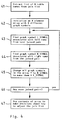
- Figure 4 shows an overview of the method.
- a list of all of N database tables referenced in the join list is made in step 41. The list need not be in any particular order.
- the graph array must be initialised with unique symbols associated with each unique table name (42). These symbols can be the table names themselves, numbers, or any arbitrary symbols.
- the first table name in the list is associated with the first element in the graph array, and so forth, on a one to one basis.
- the graph array is initialised by storing a symbol in element one, a different symbol in element two, and so on, so that no two symbols in the graph array are the same.
- Each pair of table names in the join list are processed iteratively (46).
- the graph symbol associated with the left entry of the pair is found and stored in a variable L_SYMBOL (43).
- L_SYMBOL 43
- the left entry in a pair of table names is assigned priority over the right entry as will be explained.
- the graph symbol associated with the right entry of the pair is found and stored in a variable R_SYMBOL (44).
- the graph array is searched for all occurrences of the graph symbol stored in the variable R_SYMBOL and each occurrence is replaced with the graph symbol of the higher priority left entry stored in the variable L_SYMBOL (45).
- the contents of the graph array contain a simple representation of the number and content of the groups of tables which can easily be used to make decisions about adjusting the join list (47).
- the method exploits the commutative property of the join relationship to simplify the number of graph symbols down to the minimum. Thus, the number of different graph symbols found in the array at the end of the process exactly corresponds to the number of graphs in the join list.
- the join list must ultimately be adjusted to contain only one separately linked group of tables. Any logical basis for selection of one of the groups may be used. If the group containing the largest number of tables or the group containing the largest number of joins is selected, the maximum amount of the work previously performed by the user in specifying the joins might be preserved. Another logical rule for selecting the group, might be to select the group which contains the table name first entered by the user. Allowing the user to select the group after being prompted with meaningful information about the groups would be reasonable option. The user can also be given the opportunity to enter additional join statements at different points during the adjustment process.
- Figure 5 shows an example of how part of the algorithm might be described in pseudo-code.
- N must contain the number of tables in the join list.
- the names of the tables must be in a list which can be accessed by the function NUMERIC_INDEX() which takes a table name as its input and returns the numerical index which corresponds to the table name.
- the numerical index can be thought of as the position of the name in the list.
- the code to create the name list and the code for the function NUMERIC_INDEX() are not shown.
- GRAPH_IDENTIFIERS and GRAPH_ID_COUNT are initialised. GRAPH_IDENTIFIERS will be used to track membership in a graph.
- GRAPH_ID_COUNT will be used to count the number of tables in each graph. Preferably these arrays will be created and updated in the memory of the computer.
- each element of GRAPH_IDENTIFIERS from 1 to N is set equal to a unique number from 1 to N.
- each element of GRAPH_ID_COUNT is set equal to zero.
- the graph processing is performed in lines 505 through 513. One pass through the outer loop is made for each entry in the join list (line 505).
- the current graph symbol for the left entry in the joined pair is found by feeding the name in the left entry through the NUMERIC_INDEX() function to get the index for the table name which is then used to reference the graph symbol in the GRAPH_IDENTIFIERS array.
- the graph symbol is placed in the variable L_SYMBOL.
- line 507 the current graph symbol for the right entry in the joined pair is found in a similar manner and placed in the variable R_SYMBOL.
- the left entry in a joined pair has priority over the right.
- the GRAPH_IDENTIFIERS array is adjusted by changing all lower priority symbols which are equal to the contents of R_SYMBOL by replacing them with the contents of the higher priority L_SYMBOL.
- the information in the GRAPH_IDENTIFIERS array is ready for further processing. Any elements that contain the same graph symbol represent nodes in the same graph.
- the variable MULTIPLE_GRAPHS is initialised as false.
- Each element in the GRAPH_IDENTIFIERS array is examined to accumulate statistics (lines 515 through 520). If all of the symbols in the GRAPH_IDENTIFIERS array are not equal, then MULTIPLE_GRAPHS will be set to true (lines 518, 519). In lines 516 and 517 the number of tables in each group is counted in the GRAPH_ID_COUNT array.
- the NUMERIC_INDEX() function returns the number 1 for the index of the table name first entered by the user, then the group containing the first entered table name consists of all of the nodes which have the same symbol as in GRAPH_IDENTIFIERS(1).
- the group containing the largest number of tables can be found by finding the index of the largest number in the GRAPH_ID_COUNT array. This index can then be used to find the graph symbol for the group in the GRAPH_IDENTIFIERS array.
- the graph symbol can then be used to find all of the members of the group. Since every unique symbol in the GRAPH_IDENTIFIERS array now represents a separate group, these groups can easily be determined and displayed for selection or manipulation by a user.
- Fig. 3 is the list of table names from the join list for Fig. 3.
- the initialised GRAPH_IDENTIFIERS array is labelled as 62.
- Initial unique symbols, the numbers '1' through '5', are placed in the array elements to represent all of the possible graphs and thereby initialise the graph identifiers to values corresponding to the table names.
- Table name A is associated with the first element of the GRAPH_IDENTIFIERS array and, therefore, the initial graph symbol for table A is '1'.
- Each table name is similarly associated with the corresponding array element as shown by the the dotted lines in Fig. 6. Since Fig.
- Figure 7 is an example of a computer system including a PQS.
- a data storage device such as disk drives 71 will typically contain both database tables and the computer programs which comprise the interactive database retrieval system. A small system might also use diskettes in the place of disk drives.
- the processor 74 When the computer programs are first installed there are no database tables. The tables are subsequently created by the user executing the programs.
- the processor 74 When the user enters appropriate commands on the terminal 75, the processor 74 will typically load the PQS program 76 into the memory 72 from a disk drive.
- the PQS will typically run in memory under the query processor portion of the database system 73.
- the commands, statements and information entered by the user on the terminal are translated into the input language of the query processor which might, for example, be the standard query language SQL.
- the prompts generated by the PQS are displayed on the terminal.
- a PQS implementing the method of the invention can be prepared using standard computer programming techniques.
- the executable code for the PQS can be stored in machine readable form in a ROM, on a diskette, on a magnetic tape, or in any other memory device from which a computer can retrieve data which can be loaded into memory and executed as a program.
- the method and system described above utilising graphical analysis techniques allow a PQS to break down a join list into its separately linked groups so that the join list can be adjusted in an intelligent way by selecting one of the groups and/or adding additional joins.
- the ability to analyse the join list represents an advance over the methods and systems of the prior art.
- the array 66 is used to provide the indication of how to select a group of join statements to retrieve data from the memory device in an advantageous way which provides an improvement in the operating efficiency of the computer system.
Landscapes
- Engineering & Computer Science (AREA)
- Databases & Information Systems (AREA)
- Theoretical Computer Science (AREA)
- Physics & Mathematics (AREA)
- Data Mining & Analysis (AREA)
- General Engineering & Computer Science (AREA)
- General Physics & Mathematics (AREA)
- Software Systems (AREA)
- Mathematical Physics (AREA)
- Computational Linguistics (AREA)
- Information Retrieval, Db Structures And Fs Structures Therefor (AREA)
Abstract
Description
- The present invention relates to a method and apparatus for retrieving data by entering a data retrieval request including a set of join statements linking the names of tables in data storage means.
- One method of organising a computer database is to separate the data into tables which consist of rows and columns of data. For example, in a table of employee data a row might contain information about a particular employee while a column might contain the department number of each employee. A database will typically have many tables and each table will typically have multiple rows and multiple columns.
- Data may be retrieved from this type of database by a variety of methods. For example, a computer program can extract information from the database without human intervention or a user can interact with a query system program which serves as a front-end to the database system. It is conventional for these query system programs to prompt the user for information to make the task of entering the required information for the retrieval easier. These systems are known as prompted query systems (PQS).
- A user interacting with a PQS will typically be prompted to specify which tables are to be searched and to specify relationships between various columns of the tables. Specifying the column relationships between tables is called joining the tables. Tables are joined by pairwise association of columns between the tables. Joins allow additional information to be obtained across tables in a meaningful way so that data in one table may explain or clarify data in another table. For example, an Employee-table row for an employee may list the employee's department number as '76', but the definition of department '76' requires reference to another table, the Department-table, which lists the full department title associated with each department number. In this second table the row for department '76' also contains a column with the department title "Information Systems Department." Thus, a user desiring to generate a report containing a list of all employees including their department titles may want to establish a join relationship between the department number column in the Employee-table and the department title column in the Department-table, so that the employee's department can be printed in the title form instead of the numerical form.
- Joins are specified to the PQS by entering statements such as
W AND X
X AND Y
Y AND Z
where W, X, Y and Z are symbolic names given to columns in specific tables. A join implies four pieces of information: two table names and two column names. When the user enters a column name, a table name is implied or referenced indirectly. The table names corresponding to columns W, X, etc., can be written as T(W), T(X), etc. to indicate that the table name can be found based on the column name. The PQS must maintain a join list which contains sufficient information to fully specify all of the current joins. The information in the join list in this context can be symbolic names such as 'Q.TAB1', memory addresses which allow the referenced information to be found, or any other means of indirect referencing. The join list can also be simply the list of join statements. - During an interactive session with a PQS a user may develop the final query through a trial and error process during which the user may make mistakes in specifying tables or joins or may delete a previously specified table or join. For these reasons among others, it is necessary that the join list be analysed for coherence. When one or more joins are removed from a list that was previously coherent, the list may no longer be coherent. For example, if the X AND Y join were deleted from the three joins listed above and T(W), T(X), T(Y), and T(Z) were all separate tables, there would be no link between the W-X pair and the Y-Z pair. When this situation arises a PQS must take some action. In the prior art the action taken is to erase the entire join list and force the user to build a new list of joins. This can cause the user to have to redo a significant amount of work, especially when joins exist between multiple columns of two tables.
- According to the present invention there is provided a data processing apparatus having data storage means to store a plurality of data base tables, and a user terminal for retrieving data by entering a data retrieval request including a set of join statements, each join statement linking the names of two of the tables stored in the data storage means, characterised in that means are provided to assign priority to one table name in each join statement, means are provided to form an array of graph identifiers corresponding to the table names in the set of entered joint statements, each graph identifier being initialised to have a value representing the corresponding table name, and means are provided to process each join statement in succession and substitute in the array of graph identifier values the value of the priority name in the join statement in place of the or each value representing the other name in the join statement thereby to derive in the array an indication of the number of groups of linked names in the set of entered join statements, the apparatus being operable to retrieve data by reference to the said array indication.
- Further according to the present invention there is provided a method of retrieving data from data storage means having a plurality of database tables stored therein, the method comprising entering a data retrieval request including a set of join statements, each join statement linking the names of two of the tables of the data storage means, characterised in that the method includes the steps of assigning priority to one table name in each join statement, forming an array of graph identifiers corresponding to the table names in the set of entered join statements, initialising each graph identifier to have a value representing the corresponding table name, processing the join statements in succession to substitute in the array of graph identifier values the value of the priority name in each join statement in place of the or each value representing the other name in the join statement thereby to derive in the array an indication of the number of groups of linked names in the set of entered join statements, and operating the data storage means to retrieve data by reference to the said array indication.
- The present invention is a method and a computer database system for analysing the list of joins to determine whether all of the tables in the join list are joined to each other and take reasonable action if they are not. First, the groups of separately linked database table names are determined. If more than one group exists, then adjustment of the join list is required. If T(W) is joined to T(X) and T(X) is joined to T(Y), then T(W), T(X), and T(Y) are said to be in a linked group. If no other tables are in the group, then it is a separately linked group. If T(Z) is joined to other tables, then there is a second separately linked group. The join list may be adjusted to consist of any one of the groups by deleting from the join list all joined pairs not corresponding to the selected group. The selected group can be determined automatically by the PQS by determining the group which contains the first table name entered by the user, by determining the group containing the highest number of tables or joins, by prompting the user to select the group, or by any other logical process. The user can also be prompted to enter additional join statements either before or after the join list has been adjusted. In this manner coherency of the join list is assured without the need for re-entering all of the elements of the join list.
- In the drawings:
- Figure 1 shows a sample join list,
- Figure 2 is a graphical representation of the join relationships between the tables from the join list of Fig. 1,
- Figure 3 shows the table relationships of Fig. 2 after the deletion of some joins,
- Figure 4 is an overview of a method according to the invention,
- Figure 5 is an example of pseudo-code for a partial embodiment of the method of Figure 4,
- Figure 6 is an example showing the intermediate states of a graph array between the initial state and the final state and,
- Figure 7 is an overview of a computer system embodying the present invention.
- The preferred method according to the invention of analysing the join list is to use a technique based on graph theory. Graphs may be defined symbolically, as well as, pictorially. A graph is a set of nodes connected together by lines. If the tables referenced in the join list are represented as the nodes of a graph, then the joins can be represented as lines connecting the nodes.
- Figure 1 shows an example of a simple join list containing six join statements. The names of the tables are listed as A, B, C, D and E. The names in the 'Left' and 'Right' columns are the table names that were referenced on the left and right sides respectively of a join statement entered by the user. The corresponding left and right table column names, CL and CR, are left blank, since they are not required except as needed to derive their associated table names. Each row in this list represents a joined pair of tables. For example, the first row indicates that table A is joined to table B, and the last row indicates that table D is joined to table E. There is no inherent limit to the number entries a join list may have. There is no specific format that a join list is required to have. All that is required is that the information in the join list be sufficient to identify the tables of the join relationships.
- Figure 2 shows a graphical representation of the join list of Fig. 1. The tables are represented by nodes containing the name of the table. A join relationship, i.e., a line connecting two nodes, can be referenced symbolically by referring to the two nodes that the line connects. Thus, AB is a join relationship between tables A and B. Given these conventions the symbolic representation of the graph of Fig. 2 is Nodes(A,B,C,D,E), Lines(AB,BC,BD,CE,DE,DE).
- Deleting a join relationship or a table is equivalent to deleting a line or a node of a graph. After one or more deletions there may exist multiple groups of separately linked nodes causing what was previously one graph to become multiple graphs. As used herein the term graph means a group of separately linked nodes representing database table names.
- Pictorially the deletion of a join results in the removal of the corresponding line from the diagram. Deletion of a table results in the removal of the corresponding node and all of its connecting lines from the diagram. If line CE is deleted from Fig. 2, the structure is still one graph. If line BD is also deleted, then there are two separately linked groups of nodes comprising two separate graphs. This condition is shown in Fig. 3. When the graphs are drawn, a human being can visually determine whether there is more than one group of nodes. A machine implementable method for performing this analysis in a PQS must use a different approach.
- The join list is used to determine the number of graphs. A set of N nodes can make from one to N graphs. An array of N elements is used to keep track of which tables belong in which graphs. This will be called the graph array. Figure 4 shows an overview of the method. A list of all of N database tables referenced in the join list is made in
step 41. The list need not be in any particular order. Next the graph array must be initialised with unique symbols associated with each unique table name (42). These symbols can be the table names themselves, numbers, or any arbitrary symbols. The first table name in the list is associated with the first element in the graph array, and so forth, on a one to one basis. The graph array is initialised by storing a symbol in element one, a different symbol in element two, and so on, so that no two symbols in the graph array are the same. Each pair of table names in the join list are processed iteratively (46). For the pair of table names currently being processed the graph symbol associated with the left entry of the pair is found and stored in a variable L_SYMBOL (43). The left entry in a pair of table names is assigned priority over the right entry as will be explained. The graph symbol associated with the right entry of the pair is found and stored in a variable R_SYMBOL (44). The graph array is searched for all occurrences of the graph symbol stored in the variable R_SYMBOL and each occurrence is replaced with the graph symbol of the higher priority left entry stored in the variable L_SYMBOL (45). After all of the pairs in the join list have been processed, the contents of the graph array contain a simple representation of the number and content of the groups of tables which can easily be used to make decisions about adjusting the join list (47). The method exploits the commutative property of the join relationship to simplify the number of graph symbols down to the minimum. Thus, the number of different graph symbols found in the array at the end of the process exactly corresponds to the number of graphs in the join list. - The join list must ultimately be adjusted to contain only one separately linked group of tables. Any logical basis for selection of one of the groups may be used. If the group containing the largest number of tables or the group containing the largest number of joins is selected, the maximum amount of the work previously performed by the user in specifying the joins might be preserved. Another logical rule for selecting the group, might be to select the group which contains the table name first entered by the user. Allowing the user to select the group after being prompted with meaningful information about the groups would be reasonable option. The user can also be given the opportunity to enter additional join statements at different points during the adjustment process.
- Figure 5 shows an example of how part of the algorithm might be described in pseudo-code. At the start of the pseudo-code example N must contain the number of tables in the join list. The names of the tables must be in a list which can be accessed by the function NUMERIC_INDEX() which takes a table name as its input and returns the numerical index which corresponds to the table name. The numerical index can be thought of as the position of the name in the list. The code to create the name list and the code for the function NUMERIC_INDEX() are not shown. In
lines 501 through 504 the two arrays used in the pseudo-code, GRAPH_IDENTIFIERS and GRAPH_ID_COUNT are initialised. GRAPH_IDENTIFIERS will be used to track membership in a graph. GRAPH_ID_COUNT will be used to count the number of tables in each graph. Preferably these arrays will be created and updated in the memory of the computer. Inline 502 each element of GRAPH_IDENTIFIERS from 1 to N is set equal to a unique number from 1 to N. Inline 503 each element of GRAPH_ID_COUNT is set equal to zero. The graph processing is performed inlines 505 through 513. One pass through the outer loop is made for each entry in the join list (line 505). Inline 506 the current graph symbol for the left entry in the joined pair is found by feeding the name in the left entry through the NUMERIC_INDEX() function to get the index for the table name which is then used to reference the graph symbol in the GRAPH_IDENTIFIERS array. The graph symbol is placed in the variable L_SYMBOL. Inline 507 the current graph symbol for the right entry in the joined pair is found in a similar manner and placed in the variable R_SYMBOL. As will be recalled the left entry in a joined pair has priority over the right. In the inner loop (lines 509 to 512) the GRAPH_IDENTIFIERS array is adjusted by changing all lower priority symbols which are equal to the contents of R_SYMBOL by replacing them with the contents of the higher priority L_SYMBOL. - After all of the joined pairs have been processed the information in the GRAPH_IDENTIFIERS array is ready for further processing. Any elements that contain the same graph symbol represent nodes in the same graph. In
line 514 the variable MULTIPLE_GRAPHS is initialised as false. Each element in the GRAPH_IDENTIFIERS array is examined to accumulate statistics (lines 515 through 520). If all of the symbols in the GRAPH_IDENTIFIERS array are not equal, then MULTIPLE_GRAPHS will be set to true (lines 518, 519). Inlines - If the NUMERIC_INDEX() function returns the
number 1 for the index of the table name first entered by the user, then the group containing the first entered table name consists of all of the nodes which have the same symbol as in GRAPH_IDENTIFIERS(1). The group containing the largest number of tables can be found by finding the index of the largest number in the GRAPH_ID_COUNT array. This index can then be used to find the graph symbol for the group in the GRAPH_IDENTIFIERS array. The graph symbol can then be used to find all of the members of the group. Since every unique symbol in the GRAPH_IDENTIFIERS array now represents a separate group, these groups can easily be determined and displayed for selection or manipulation by a user. - The example of Fig. 3 will be traced to further clarify the approach. In Figure 6, 61 is the list of table names from the join list for Fig. 3. The initialised GRAPH_IDENTIFIERS array is labelled as 62. Initial unique symbols, the numbers '1' through '5', are placed in the array elements to represent all of the possible graphs and thereby initialise the graph identifiers to values corresponding to the table names. Table name A is associated with the first element of the GRAPH_IDENTIFIERS array and, therefore, the initial graph symbol for table A is '1'. Each table name is similarly associated with the corresponding array element as shown by the the dotted lines in Fig. 6. Since Fig. 3 has four lines, there will be four processing passes through the main loop to process each join statement in succession (see Fig. 4, steps 43 through 46, and Fig. 5,
lines 505 through 513). The lines representing the joins can be processed in any order. In this case BC will be processed first. The left table entry of this pair is B which has an associated index of 2. The second element in the GRAPH_IDENTIFIERS array is '2', so L_SYMBOL is set to '2' (see Fig. 4, steps 43 and Fig. 5, line 506). The right table entry of this pair is C which has an associated index of 3. The third element in the GRAPH_IDENTIFIERS array is '3', so R_SYMBOL is set to '3' (see Fig. 4,step 44 and Fig. 5, line 507). Now priority is assigned to the left table entry of each pair and consequently all elements of the array which are equal to '3' are changed to '2' (Fig. 6, array 63 (steps 510 and 511)). Examination of the array now shows that B and C are in the same graph because they have the same graph symbol, i.e., '2'. The join of AB causes all of the nodes formerly grouped with B to be regrouped with A (array 64). At this point it can be seen that A and C are in the same group although they are not directly joined. The DE join causes the graph symbol for E to be replaced with the graph symbol for D (array 65). Processing another join for DE causes no change in the array contents (array 66). The final contents of the array readily reveal that there are two graphs representing two separately linked groups of tables and that the largest number of tables in one group is three. - Figure 7 is an example of a computer system including a PQS. A data storage device such as disk drives 71 will typically contain both database tables and the computer programs which comprise the interactive database retrieval system. A small system might also use diskettes in the place of disk drives. When the computer programs are first installed there are no database tables. The tables are subsequently created by the user executing the programs. When the user enters appropriate commands on the terminal 75, the
processor 74 will typically load thePQS program 76 into thememory 72 from a disk drive. The PQS will typically run in memory under the query processor portion of thedatabase system 73. The commands, statements and information entered by the user on the terminal are translated into the input language of the query processor which might, for example, be the standard query language SQL. The prompts generated by the PQS are displayed on the terminal. - A PQS implementing the method of the invention can be prepared using standard computer programming techniques. The executable code for the PQS can be stored in machine readable form in a ROM, on a diskette, on a magnetic tape, or in any other memory device from which a computer can retrieve data which can be loaded into memory and executed as a program.
- The method and system described above utilising graphical analysis techniques allow a PQS to break down a join list into its separately linked groups so that the join list can be adjusted in an intelligent way by selecting one of the groups and/or adding additional joins. The ability to analyse the join list represents an advance over the methods and systems of the prior art. Thus the
array 66 is used to provide the indication of how to select a group of join statements to retrieve data from the memory device in an advantageous way which provides an improvement in the operating efficiency of the computer system.
Claims (6)
- Data processing apparatus having data storage means to store a plurality of data base tables, and a user terminal for retrieving data by entering a data retrieval request including a set of join statements, each join statement linking the names of two of the tables stored in the data storage means, characterised in that means are provided to assign priority to one table name in each join statement, means are provided to form an array of graph identifiers corresponding to the table names in the set of entered joint statements, each graph identifier being initialised to have a value representing the corresponding table name, and means are provided to process each join statement in succession and substitute in the array of graph identifier values the value of the priority name in the join statement in place of the or each value representing the other name in the join statement thereby to derive in the array an indication of the number of groups of linked names in the set of entered join statements, the apparatus being operable to retrieve data by reference to the said array indication.
- Apparatus according to claim 1 wherein means are provided to prompt the user to select a group of linked names by reference to the said array indication.
- Apparatus according to claim 1 wherein means are provided to determine a group of linked names containing the largest number of names.
- Apparatus according to claim 1 wherein means are provided to select a group of linked names containing a name which is the first entered in the set of join statements.
- Apparatus according to any one of claims 1 to 4 wherein the means to assign priority is operable to select the first (L-SYMBOL) name in each join statement to have priority over the second (R-SYMBOL) name in the statement.
- A method of retrieving data from data storage means having a plurality of database tables stored therein, the method comprising entering a data retrieval request including a set of join statements, each join statement linking the names of two of the tables of the data storage means, characterised in that the method includes the steps of assigning priority to one table name in each join statement, forming an array of graph identifiers corresponding to the table names in the set of entered join statements, initialising each graph identifier to have a value representing the corresponding table name, processing the join statements in succession to substitute in the array of graph identifier values the value of the priority name in each join statement in place of the or each value representing the other name in the join statement thereby to derive in the array an indication of the number of groups of linked names in the set of entered join statements, and operating the data storage means to retrieve data by reference to the said array indication.
Applications Claiming Priority (2)
| Application Number | Priority Date | Filing Date | Title |
|---|---|---|---|
| US576022 | 1990-08-31 | ||
| US07/576,022 US5287493A (en) | 1990-08-31 | 1990-08-31 | Database interactive prompted query system having named database tables linked together by a user through join statements |
Publications (3)
| Publication Number | Publication Date |
|---|---|
| EP0476810A2 true EP0476810A2 (en) | 1992-03-25 |
| EP0476810A3 EP0476810A3 (en) | 1993-10-20 |
| EP0476810B1 EP0476810B1 (en) | 1998-10-14 |
Family
ID=24302657
Family Applications (1)
| Application Number | Title | Priority Date | Filing Date |
|---|---|---|---|
| EP91306546A Expired - Lifetime EP0476810B1 (en) | 1990-08-31 | 1991-07-18 | Method and system for retrieving data from joined tables in a computer database |
Country Status (4)
| Country | Link |
|---|---|
| US (1) | US5287493A (en) |
| EP (1) | EP0476810B1 (en) |
| JP (1) | JPH0769923B2 (en) |
| DE (1) | DE69130350T2 (en) |
Cited By (3)
| Publication number | Priority date | Publication date | Assignee | Title |
|---|---|---|---|---|
| EP0679277A4 (en) * | 1992-07-24 | 1995-07-05 | Sheridan Bentson | Method and apparatus for displaying and updating structured information. |
| CN1048346C (en) * | 1993-03-03 | 2000-01-12 | 松下电器产业株式会社 | Dictionary serching apparatus |
| CN1048345C (en) * | 1992-08-05 | 2000-01-12 | 松下电器产业株式会社 | Chinese character vary apparatus |
Families Citing this family (15)
| Publication number | Priority date | Publication date | Assignee | Title |
|---|---|---|---|---|
| US5469568A (en) * | 1993-01-07 | 1995-11-21 | International Business Machines Corporation | Method for choosing largest selectivities among eligible predicates of join equivalence classes for query optimization |
| JP2710548B2 (en) * | 1993-03-17 | 1998-02-10 | インターナショナル・ビジネス・マシーンズ・コーポレイション | Method for retrieving data and converting between Boolean algebraic and graphic representations |
| US5544352A (en) * | 1993-06-14 | 1996-08-06 | Libertech, Inc. | Method and apparatus for indexing, searching and displaying data |
| US5519859A (en) * | 1993-11-15 | 1996-05-21 | Grace; John A. | Method and apparatus for automatic table selection and generation of structured query language instructions |
| US5745746A (en) * | 1996-06-24 | 1998-04-28 | International Business Machines Corporation | Method for localizing execution of subqueries and determining collocation of execution of subqueries in a parallel database |
| USRE37965E1 (en) | 1995-09-27 | 2003-01-07 | International Business Machines Corporation | Method for localizing execution or subqueries and determining collocation of execution of subqueries in a parallel database |
| US5692181A (en) * | 1995-10-12 | 1997-11-25 | Ncr Corporation | System and method for generating reports from a computer database |
| US5903893A (en) * | 1997-09-15 | 1999-05-11 | International Business Machines Corporation | Method and apparatus for optimizing a merge-join operation across heterogeneous databases |
| US6757677B2 (en) * | 2001-09-28 | 2004-06-29 | Ncr Corporation | Providing a join plan using group-by operator |
| EP1349082A1 (en) * | 2002-03-28 | 2003-10-01 | LION Bioscience AG | Method and apparatus for querying relational databases |
| EP1349081A1 (en) * | 2002-03-28 | 2003-10-01 | LION Bioscience AG | Method and apparatus for querying relational databases |
| GB2401211B (en) * | 2003-04-30 | 2005-07-20 | Oracle Int Corp | SQL join elimination |
| US9165040B1 (en) | 2006-10-12 | 2015-10-20 | Google Inc. | Producing a ranking for pages using distances in a web-link graph |
| US9229982B2 (en) * | 2008-12-23 | 2016-01-05 | SAP France S.A. | Processing queries using oriented query paths |
| US20150356175A1 (en) * | 2014-06-05 | 2015-12-10 | Kpmg Llp | System and method for finding and inventorying data from multiple, distinct data repositories |
Family Cites Families (1)
| Publication number | Priority date | Publication date | Assignee | Title |
|---|---|---|---|---|
| JPH01181125A (en) * | 1988-01-13 | 1989-07-19 | Nippon Steel Corp | Relation type data base device |
-
1990
- 1990-08-31 US US07/576,022 patent/US5287493A/en not_active Expired - Fee Related
-
1991
- 1991-06-11 JP JP3165261A patent/JPH0769923B2/en not_active Expired - Lifetime
- 1991-07-18 EP EP91306546A patent/EP0476810B1/en not_active Expired - Lifetime
- 1991-07-18 DE DE69130350T patent/DE69130350T2/en not_active Expired - Fee Related
Non-Patent Citations (1)
| Title |
|---|
| IBM TECHNICAL DISCLOSURE BULLETIN. vol. 30, no. 9, February 1988, NEW YORK US pages 8 - 10 'Heuristic Method for Joining Relational Data Base Tables' * |
Cited By (4)
| Publication number | Priority date | Publication date | Assignee | Title |
|---|---|---|---|---|
| EP0679277A4 (en) * | 1992-07-24 | 1995-07-05 | Sheridan Bentson | Method and apparatus for displaying and updating structured information. |
| EP0679277A1 (en) * | 1992-07-24 | 1995-11-02 | BENTSON, Sheridan | Method and apparatus for displaying and updating structured information |
| CN1048345C (en) * | 1992-08-05 | 2000-01-12 | 松下电器产业株式会社 | Chinese character vary apparatus |
| CN1048346C (en) * | 1993-03-03 | 2000-01-12 | 松下电器产业株式会社 | Dictionary serching apparatus |
Also Published As
| Publication number | Publication date |
|---|---|
| DE69130350T2 (en) | 1999-06-02 |
| DE69130350D1 (en) | 1998-11-19 |
| EP0476810B1 (en) | 1998-10-14 |
| US5287493A (en) | 1994-02-15 |
| JPH04237374A (en) | 1992-08-25 |
| EP0476810A3 (en) | 1993-10-20 |
| JPH0769923B2 (en) | 1995-07-31 |
Similar Documents
| Publication | Publication Date | Title |
|---|---|---|
| EP0476810B1 (en) | Method and system for retrieving data from joined tables in a computer database | |
| US5594898A (en) | Method and system for joining database tables using compact row mapping structures | |
| US5893088A (en) | System and method for performing database query using a marker table | |
| US5021992A (en) | Method of translating data from knowledge base to data base | |
| EP0375307B1 (en) | Structure for and method of arranging recursively derived data in a database | |
| US5727196A (en) | Optimized query interface for database management systems | |
| US5960428A (en) | Star/join query optimization | |
| US5257365A (en) | Database system with multi-dimensional summary search tree nodes for reducing the necessity to access records | |
| US8386435B2 (en) | Searchable archive | |
| EP1360616B1 (en) | Database system and query optimiser | |
| US6185556B1 (en) | Method and apparatus for changing temporal database | |
| US20020116373A1 (en) | Database management system, and query method and query execution program in the database management system | |
| US4893232A (en) | Data management system for efficiently searching data elements and having a flexible registration order of data elements | |
| JP2001014329A (en) | Database processing method and implementation device, and medium stored with the processing program | |
| JP3205406B2 (en) | Reference target variable determination processing method and translation processing system | |
| EP0698853A1 (en) | Method for performing joins in a database system | |
| US20020062303A1 (en) | Data management method and storage medium storing data management program | |
| US20020138464A1 (en) | Method and apparatus to index a historical database for efficient multiattribute SQL queries | |
| EP0394172A2 (en) | Method of performing file services given partial file names | |
| JPH04311263A (en) | Electronic dictionary retrieving device | |
| JPH07311780A (en) | Information retrieval device and information retrieval method | |
| JP3980326B2 (en) | Data management method and computer-readable recording medium | |
| JPH06103134A (en) | Constructing method for index | |
| JPH11242627A (en) | Data access method and medium recording program | |
| JPH0347539B2 (en) |
Legal Events
| Date | Code | Title | Description |
|---|---|---|---|
| PUAI | Public reference made under article 153(3) epc to a published international application that has entered the european phase |
Free format text: ORIGINAL CODE: 0009012 |
|
| AK | Designated contracting states |
Kind code of ref document: A2 Designated state(s): DE FR GB |
|
| 17P | Request for examination filed |
Effective date: 19920619 |
|
| PUAL | Search report despatched |
Free format text: ORIGINAL CODE: 0009013 |
|
| AK | Designated contracting states |
Kind code of ref document: A3 Designated state(s): DE FR GB |
|
| GRAG | Despatch of communication of intention to grant |
Free format text: ORIGINAL CODE: EPIDOS AGRA |
|
| 17Q | First examination report despatched |
Effective date: 19970922 |
|
| GRAG | Despatch of communication of intention to grant |
Free format text: ORIGINAL CODE: EPIDOS AGRA |
|
| GRAH | Despatch of communication of intention to grant a patent |
Free format text: ORIGINAL CODE: EPIDOS IGRA |
|
| GRAH | Despatch of communication of intention to grant a patent |
Free format text: ORIGINAL CODE: EPIDOS IGRA |
|
| GRAA | (expected) grant |
Free format text: ORIGINAL CODE: 0009210 |
|
| AK | Designated contracting states |
Kind code of ref document: B1 Designated state(s): DE FR GB |
|
| PG25 | Lapsed in a contracting state [announced via postgrant information from national office to epo] |
Ref country code: FR Free format text: LAPSE BECAUSE OF FAILURE TO SUBMIT A TRANSLATION OF THE DESCRIPTION OR TO PAY THE FEE WITHIN THE PRESCRIBED TIME-LIMIT Effective date: 19981014 |
|
| REF | Corresponds to: |
Ref document number: 69130350 Country of ref document: DE Date of ref document: 19981119 |
|
| EN | Fr: translation not filed | ||
| PGFP | Annual fee paid to national office [announced via postgrant information from national office to epo] |
Ref country code: DE Payment date: 19990715 Year of fee payment: 9 |
|
| PLBE | No opposition filed within time limit |
Free format text: ORIGINAL CODE: 0009261 |
|
| STAA | Information on the status of an ep patent application or granted ep patent |
Free format text: STATUS: NO OPPOSITION FILED WITHIN TIME LIMIT |
|
| 26N | No opposition filed | ||
| PGFP | Annual fee paid to national office [announced via postgrant information from national office to epo] |
Ref country code: GB Payment date: 20000629 Year of fee payment: 10 |
|
| PG25 | Lapsed in a contracting state [announced via postgrant information from national office to epo] |
Ref country code: DE Free format text: LAPSE BECAUSE OF NON-PAYMENT OF DUE FEES Effective date: 20010501 |
|
| PG25 | Lapsed in a contracting state [announced via postgrant information from national office to epo] |
Ref country code: GB Free format text: LAPSE BECAUSE OF NON-PAYMENT OF DUE FEES Effective date: 20010718 |
|
| GBPC | Gb: european patent ceased through non-payment of renewal fee |
Effective date: 20010718 |