EP0476993A2 - Video effects system - Google Patents
Video effects system Download PDFInfo
- Publication number
- EP0476993A2 EP0476993A2 EP91308512A EP91308512A EP0476993A2 EP 0476993 A2 EP0476993 A2 EP 0476993A2 EP 91308512 A EP91308512 A EP 91308512A EP 91308512 A EP91308512 A EP 91308512A EP 0476993 A2 EP0476993 A2 EP 0476993A2
- Authority
- EP
- European Patent Office
- Prior art keywords
- image
- generating
- dimensional image
- depth
- real time
- Prior art date
- Legal status (The legal status is an assumption and is not a legal conclusion. Google has not performed a legal analysis and makes no representation as to the accuracy of the status listed.)
- Ceased
Links
Images


Classifications
-
- H—ELECTRICITY
- H04—ELECTRIC COMMUNICATION TECHNIQUE
- H04N—PICTORIAL COMMUNICATION, e.g. TELEVISION
- H04N5/00—Details of television systems
- H04N5/222—Studio circuitry; Studio devices; Studio equipment
- H04N5/262—Studio circuits, e.g. for mixing, switching-over, change of character of image, other special effects ; Cameras specially adapted for the electronic generation of special effects
- H04N5/2628—Alteration of picture size, shape, position or orientation, e.g. zooming, rotation, rolling, perspective, translation
-
- H—ELECTRICITY
- H04—ELECTRIC COMMUNICATION TECHNIQUE
- H04N—PICTORIAL COMMUNICATION, e.g. TELEVISION
- H04N5/00—Details of television systems
- H04N5/222—Studio circuitry; Studio devices; Studio equipment
- H04N5/262—Studio circuits, e.g. for mixing, switching-over, change of character of image, other special effects ; Cameras specially adapted for the electronic generation of special effects
- H04N5/272—Means for inserting a foreground image in a background image, i.e. inlay, outlay
Definitions
- This invention relates to a video effects system, and more particularly to a system that is able to intersect a 3-D image with a 2-D image.
- Digital video effects (DVE) devices such as the ADO manufactured by Ampex Corporation of Palo Alto, California and the Kaleidoscope manufactured by The Grass Valley Group, Inc. of Grass Valley, California, have the ability to transform a television image.
- a basic technique for doing this is to take each two-dimensional image and assign to each pixel three coordinates (X,Y,Z).
- the X and Y coordinates refer to the pixel's position on a flat surface
- the Z coordinate refers to the distance from a plane that contains the viewer's eye.
- the Z coordinate is initially set to some constant since the viewer is looking straight at a flat image.
- the DVE device then does a three-dimensional transformation on the coordinates of each pixel, such as disclosed in U. S. Patent NO. 4,797,836 issued January 10, 1989 to Francis A. Witek and David E. Lake, Jr. entitled "Image Orientation and Animation Using Quaternions".
- a transformation is the mathematical equivalent of taking the flat two-dimensional image, rotating it about one or more of the three coordinate axes, and then moving it in space.
- This transformation process takes the original X, Y and Z coordinates and maps them into a new set of coordinates X′, Y′ and Z′.
- the transformed image is then projected into the X-Y plane.
- Current DVE devices implement transformation algorithms using hardware and are able to work in real time, and the particular transform that is effected depends on an operator control, typically a joystick. Therefore, as the joystick is moved, the transform changes and the image can be rotated and translated.
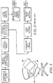
- FIG. 1 illustrates in simplified block form a digital video effects system by which two two-dimensional images can be transformed and combined.
- the FIG. 1 device comprises sources 2A, 2B of first and second analog video signals, VideoA and VideoB respectively.
- Each video signal represents a two-dimensional image that is characterized by a distribution of color information over a two-dimensional display plane.
- the video signals are accompanied by respective key signals KeyA and KeyB, which are derived from key sources 8A, 8B and represent opacity of the respective images as a function of location over the display plane.
- the video signals and the accompanying key signals are applied to converters 12A, 12B, which convert the input video signals and key signals into digital form.
- Each converter 12 may convert its input video signal into a digital signal that is compatible with a standard digital television format, such as the CCIR.601 format.
- a digital video signal in the CCIR.601 standard is composed of four-word packets. Each packet contains two luminance slots, Y, and two chrominance slots, C1, C2, multiplexed in the sequence C1 Y C2 Y. The words are up to ten bits each and the data rate is 27 million words per second. Thus, the luminance component of the video signal is digitized at 13.5 MHz and each chrominance component is digitized at half that rate.
- a signal in accordance with the CCIR.601 standard is informally referred to as a 4:2:2 signal.
- Each converter 12 has four output channels, namely a luminance channel, two chroma channels and a key channel.
- the luminance channel carries luminance information in ten bit words at 13.5 MHz
- the first chroma channel carries information pertaining to one of the chroma components in ten bit words at 6.75 MHz
- the second chroma channel carries information pertaining to the other chroma component in ten bit words at 6.75 MHz
- the key channel carries key information in ten bit words at 13.5 MHz.
- the three video channels may, if necessary, be multiplexed to provide a 4:2:2 signal.
- the four output channels of converter 12 are applied to a transform section 14 where the input video signal, representing color as a function of position in the display plane, is manipulated in three dimensions to simulate transformation (translation and/or rotation of the two-dimensional image) of the image in a three-dimensional space and projection of the transformed 2-D image back into the display plane.
- the transformation may be effected by loading the values of Y, C1 and C2 into a frame buffer at addresses that depend on time relative to the sync signals of the input video signal and reading the values out at different times relative to the sync signals of the output video signal, whereby a quartet of values C1,Y,C2,Y is shifted to a different location in the raster.
- the key signal is transformed in similar manner.
- the nature of the transform can be selectively altered in real time by use of a joystick 15.
- values of depth (Z) relative to the display plane are calculated to twenty bits.
- Each transform section has six digital output channels.
- Three output channels carry a digital video signal VideoA′ or VideoB′, representing the projection of the transformed two-dimensional image into the display plane, in the same form as the digital input video signal.
- the fourth channel carries the transformed key signal KeyA′ or KeyB′ in the same form as the input key signal.
- the twenty-bit depth words are each divided into two ten-bit components Z1 and Z2, which are carried by the fifth and sixth channels respectively at 6.75 MHz.
- the key and depth channels may, if necessary, be multiplexed to provide a signal similar to a 4;2;2 video signal.
- the output signals of the two transform sections 14A, 14B are input to a depth combiner 16.
- Combiner 16 combines the transformed video signals VideoA′ and VideoB′ on the basis of the respective key and depth signals and generates a combined output video signal VideoC.
- Combiner 16 also combines the transformed key signals KeyA′ and KeyB′ using well understood rules and generates a key signal KeyC, and generates a depth signal Z C whose value is equal to the smaller of Z A ′ and Z B ′.
- Combiner 16 includes a multiplexer that multiplexes the luminance and chroma information of signal VideoC such that the output video signal is in accordance with CCIR.601.
- Combiner 16 also includes a multiplexer that multiplexes the key and depth signals and provides a signal in a form similar to the CCIR.601 format, each packet containing two ten-bit words of key and one twenty-bit word of depth in two parts of ten bits each.
- each transformed image may have pixels that map to the same X′ and Y′ coordinates, so that the two images intersect.
- FIG. 2 illustrates in simplified form the operations performed by a graphics generator, such as the Graphics Factory manufactured by Dubner Computer Systems, Inc. of Paramus, New Jersey.
- the graphics generator first generates three-dimensional image data, for example by specifying a set of points in space that are to be connected. The points are connected by lines, and polygons are thereby defined. The polygons are broken down into smaller and smaller polygons, until a set of polygons is obtained such that each polygon defines a surface patch that is planar within a predetermined tolerance. In this fashion, a data base is created containing locations in a three-dimensional space (X,Y,Z) of the vertices of polygonal surface patches.
- X,Y,Z three-dimensional space
- the viewing direction might be specified as along one of the axes of symmetry of the ellipsoid. This viewing direction is fixed relative to the image.
- a three-dimensional transformation is then carried out on the image data so as to displace and orient the image so that the viewing direction lies on the Z axis. This is accomplished by use of a software implementation of transformation algorithms that are similar to those used by a DVE device for rotating and moving an object in three-dimensional space.
- a lighting model is applied to the transformed image so as to generate, for each surface patch, a perceived color that takes account of light source, viewing direction, surface color and other factors.
- the image data is projected into the X-Y plane by loading the color values, which may be defined by one luminance value and two chroma values, into a frame buffer using only X and Y values to address the frame buffer.
- the color values which may be defined by one luminance value and two chroma values
- a digital video signal is generated representing the image when viewed along the selected viewing direction.
- movement of the image can be simulated.
- current graphics generators are not able to operate in real time.
- the Graphics Factory has two digital output channels. One channel carries the digital video signal in CCIR.601 form. The other channel carries a key signal in ten bit words at 13.5 MHz.
- the output signal of the graphics generator does not contain explicit depth information.
- a video effects system comprises means for generating a three-dimensional image in real time, means for generating a second image, transform means for transforming the second image in real time, and combiner means for combining the three-dimensional image with the transformed second image to produce an output image that is the intersection of the three-dimensional image and the transformed second image.
- a video effects system comprises means for generating a three-dimensional image in real time, means for generating a second image in real time, transform means for transforming the second image in real time and generating depth information associated with the transformed second image, and combiner means for combining the three-dimensional image with the transformed second image on the basis of the depth information to produce an output image that is the intersection of the three-dimensional image and the transformed second image.
- a method for carrying out a video effect comprises generating in real time a first video signal representative of a three-dimensional image and a first depth signal associated therewith, generating in real time a second video signal representative of a two-dimensional image, transforming the second video signal in real time and generating a second depth signal, and combining the first video signal with the transformed second video signal on the basis of the first and second depth signals.
- FIG. 3 illustrates apparatus similar to that shown in FIG. 1 but in which one video source and associated components have been replaced with a graphics generator 18 that operates in a manner similar to that described with reference to FIG. 2.
- the graphics generator 18 outputs a video signal representing the distribution of color information over a two-dimensional field. This video signal is generated in the manner previously described, by manipulating information relating to the locations in three-dimensional space of surface patches of a three-dimensional object, and is output in CCIR.601 form over a first output channel.
- the 4:2:2 video signal from graphics generator 18 is applied to a demultiplexer 20, which demultiplexes it into a luminance channel and two chroma channels.
- the graphics generator also has a second output channel, which carries a key signal.
- the Z values calculated by the graphics generator are used to generate a twenty-bit depth signal. Since a surface patch would in general cover more than one pixel, values of Z for pixels within the boundary of the patch are calculated from the Z values for the vertices of the patch. These calculations are simplified by the fact that each patch is assumed to be planar. Each thenty-bit Z word is divided into two parts which are carried by two further output channels respectively.
- the key/depth signals provided by the graphics generator are therefore in the same format as the key/depth signals provided by transform section 14.
- the demultiplexed video signal provided by demultiplexer 20 and the key and depth signals provided by graphics generator 18 are then combined with the output signals of the transform section 14, in similar manner to that described with reference to FIG. 1, by use of depth combiner 16.
- Combiner 16 produces an output video signal representing an output image 22, such as shown in FIG. 4, which is a two-dimensional depiction of the intersection of a two-dimensional image 24 with a three-dimensional image 26.
- the two-dimensional image can be displaced and rotated in real time within the three-dimensional space occupied by the three-dimensional image and will always slice the three-dimensional image correctly when the two images intersect.
- the system shown in FIG. 3 therefore provides a combined 3-D/2-D video effect by generating a 3-D image in slow time in a graphics generator, and then outputting the 3-D image in real time together with associated depth information to a digital video effects device for combining with another image to produce an intersection of a solid object with another image.
- the 3-D image provided by graphics generator 18 may be a still image, or it may be an image in which movement is simulated by reading out a succession of images in real time.
Abstract
Description
- This invention relates to a video effects system, and more particularly to a system that is able to intersect a 3-D image with a 2-D image.
- Digital video effects (DVE) devices, such as the ADO manufactured by Ampex Corporation of Palo Alto, California and the Kaleidoscope manufactured by The Grass Valley Group, Inc. of Grass Valley, California, have the ability to transform a television image. A basic technique for doing this, as disclosed in U. S. Patent No. 4,875,097 issued October 17, 1989 to Richard A. Jackson entitled "Perspective Processing of a Video Signal", is to take each two-dimensional image and assign to each pixel three coordinates (X,Y,Z). The X and Y coordinates refer to the pixel's position on a flat surface, and the Z coordinate refers to the distance from a plane that contains the viewer's eye. The Z coordinate is initially set to some constant since the viewer is looking straight at a flat image.
- The DVE device then does a three-dimensional transformation on the coordinates of each pixel, such as disclosed in U. S. Patent NO. 4,797,836 issued January 10, 1989 to Francis A. Witek and David E. Lake, Jr. entitled "Image Orientation and Animation Using Quaternions". Such a transformation is the mathematical equivalent of taking the flat two-dimensional image, rotating it about one or more of the three coordinate axes, and then moving it in space. This transformation process takes the original X, Y and Z coordinates and maps them into a new set of coordinates X′, Y′ and Z′. The transformed image is then projected into the X-Y plane. Current DVE devices implement transformation algorithms using hardware and are able to work in real time, and the particular transform that is effected depends on an operator control, typically a joystick. Therefore, as the joystick is moved, the transform changes and the image can be rotated and translated.
- FIG. 1 illustrates in simplified block form a digital video effects system by which two two-dimensional images can be transformed and combined. The FIG. 1 device comprises
sources key sources converters - A digital video signal in the CCIR.601 standard is composed of four-word packets. Each packet contains two luminance slots, Y, and two chrominance slots, C1, C2, multiplexed in the sequence C1 Y C2 Y. The words are up to ten bits each and the data rate is 27 million words per second. Thus, the luminance component of the video signal is digitized at 13.5 MHz and each chrominance component is digitized at half that rate. A signal in accordance with the CCIR.601 standard is informally referred to as a 4:2:2 signal.
- Each converter 12 has four output channels, namely a luminance channel, two chroma channels and a key channel. The luminance channel carries luminance information in ten bit words at 13.5 MHz, the first chroma channel carries information pertaining to one of the chroma components in ten bit words at 6.75 MHz, the second chroma channel carries information pertaining to the other chroma component in ten bit words at 6.75 MHz, and the key channel carries key information in ten bit words at 13.5 MHz. The three video channels may, if necessary, be multiplexed to provide a 4:2:2 signal.
- The four output channels of converter 12 are applied to a
transform section 14 where the input video signal, representing color as a function of position in the display plane, is manipulated in three dimensions to simulate transformation (translation and/or rotation of the two-dimensional image) of the image in a three-dimensional space and projection of the transformed 2-D image back into the display plane. The transformation may be effected by loading the values of Y, C1 and C2 into a frame buffer at addresses that depend on time relative to the sync signals of the input video signal and reading the values out at different times relative to the sync signals of the output video signal, whereby a quartet of values C1,Y,C2,Y is shifted to a different location in the raster. The key signal is transformed in similar manner. The nature of the transform can be selectively altered in real time by use of ajoystick 15. - In the transformation operation, values of depth (Z) relative to the display plane are calculated to twenty bits.
- Each transform section has six digital output channels. Three output channels carry a digital video signal VideoA′ or VideoB′, representing the projection of the transformed two-dimensional image into the display plane, in the same form as the digital input video signal. The fourth channel carries the transformed key signal KeyA′ or KeyB′ in the same form as the input key signal. The twenty-bit depth words are each divided into two ten-bit components Z1 and Z2, which are carried by the fifth and sixth channels respectively at 6.75 MHz. The key and depth channels may, if necessary, be multiplexed to provide a signal similar to a 4;2;2 video signal.
- The output signals of the two
transform sections Combiner 16 combines the transformed video signals VideoA′ and VideoB′ on the basis of the respective key and depth signals and generates a combined output video signal VideoC.Combiner 16 also combines the transformed key signals KeyA′ and KeyB′ using well understood rules and generates a key signal KeyC, and generates a depth signal ZC whose value is equal to the smaller of ZA′ and ZB′.Combiner 16 includes a multiplexer that multiplexes the luminance and chroma information of signal VideoC such that the output video signal is in accordance with CCIR.601.Combiner 16 also includes a multiplexer that multiplexes the key and depth signals and provides a signal in a form similar to the CCIR.601 format, each packet containing two ten-bit words of key and one twenty-bit word of depth in two parts of ten bits each. - By selection of the transformations that are performed on the two video images, each transformed image may have pixels that map to the same X′ and Y′ coordinates, so that the two images intersect.
- FIG. 2 illustrates in simplified form the operations performed by a graphics generator, such as the Graphics Factory manufactured by Dubner Computer Systems, Inc. of Paramus, New Jersey. The graphics generator first generates three-dimensional image data, for example by specifying a set of points in space that are to be connected. The points are connected by lines, and polygons are thereby defined. The polygons are broken down into smaller and smaller polygons, until a set of polygons is obtained such that each polygon defines a surface patch that is planar within a predetermined tolerance. In this fashion, a data base is created containing locations in a three-dimensional space (X,Y,Z) of the vertices of polygonal surface patches.
- It is then necessary for the operator to define the direction from which the image is to be viewed. If the image is, for example, an ellipsoid, the viewing direction might be specified as along one of the axes of symmetry of the ellipsoid. This viewing direction is fixed relative to the image. A three-dimensional transformation is then carried out on the image data so as to displace and orient the image so that the viewing direction lies on the Z axis. This is accomplished by use of a software implementation of transformation algorithms that are similar to those used by a DVE device for rotating and moving an object in three-dimensional space. A lighting model is applied to the transformed image so as to generate, for each surface patch, a perceived color that takes account of light source, viewing direction, surface color and other factors. The image data is projected into the X-Y plane by loading the color values, which may be defined by one luminance value and two chroma values, into a frame buffer using only X and Y values to address the frame buffer. By repeatedly reading the contents of the frame buffer, a digital video signal is generated representing the image when viewed along the selected viewing direction. Also, by creating successive frames in which the image is at different locations and/or orientations relative to the Z axis, movement of the image can be simulated. However, current graphics generators are not able to operate in real time.
- The Graphics Factory has two digital output channels. One channel carries the digital video signal in CCIR.601 form. The other channel carries a key signal in ten bit words at 13.5 MHz.
- It will be appreciated that the foregoing description is very much simplified, but since digital video effects systems and graphics generators are known in the art additional description of their operation is believed to be unnecessary.
- Although a graphics generator calculates values of Z for the transformed image, for example for use in hidden surface removal, the output signal of the graphics generator does not contain explicit depth information.
- According to a first aspect of the invention, a video effects system comprises means for generating a three-dimensional image in real time, means for generating a second image, transform means for transforming the second image in real time, and combiner means for combining the three-dimensional image with the transformed second image to produce an output image that is the intersection of the three-dimensional image and the transformed second image.
- According to a second aspect of the invention, a video effects system comprises means for generating a three-dimensional image in real time, means for generating a second image in real time, transform means for transforming the second image in real time and generating depth information associated with the transformed second image, and combiner means for combining the three-dimensional image with the transformed second image on the basis of the depth information to produce an output image that is the intersection of the three-dimensional image and the transformed second image.
- According to a third aspect of the invention, a method for carrying out a video effect comprises generating in real time a first video signal representative of a three-dimensional image and a first depth signal associated therewith, generating in real time a second video signal representative of a two-dimensional image, transforming the second video signal in real time and generating a second depth signal, and combining the first video signal with the transformed second video signal on the basis of the first and second depth signals.
- For a better understanding of the invention, and to show how the same may be carried into effect, reference will now be made, by way of example, to the accompanying drawings in which:
- FIG. 1 is a block diagram of a conventional digital video effects system for combining two video images,
- FIG. 2 is a high level flowchart illustrating operation of a graphics generator,
- FIG. 3 is a block diagram of a video effects system embodying the present invention, and
- FIG. 4 is a representative display image resulting from use of the video effects system shown in FIG. 3.
- FIG. 3 illustrates apparatus similar to that shown in FIG. 1 but in which one video source and associated components have been replaced with a graphics generator 18 that operates in a manner similar to that described with reference to FIG. 2. The graphics generator 18 outputs a video signal representing the distribution of color information over a two-dimensional field. This video signal is generated in the manner previously described, by manipulating information relating to the locations in three-dimensional space of surface patches of a three-dimensional object, and is output in CCIR.601 form over a first output channel. The 4:2:2 video signal from graphics generator 18 is applied to a demultiplexer 20, which demultiplexes it into a luminance channel and two chroma channels. The graphics generator also has a second output channel, which carries a key signal. Further, the Z values calculated by the graphics generator are used to generate a twenty-bit depth signal. Since a surface patch would in general cover more than one pixel, values of Z for pixels within the boundary of the patch are calculated from the Z values for the vertices of the patch. These calculations are simplified by the fact that each patch is assumed to be planar. Each thenty-bit Z word is divided into two parts which are carried by two further output channels respectively. The key/depth signals provided by the graphics generator are therefore in the same format as the key/depth signals provided by
transform section 14. The demultiplexed video signal provided by demultiplexer 20 and the key and depth signals provided by graphics generator 18 are then combined with the output signals of thetransform section 14, in similar manner to that described with reference to FIG. 1, by use ofdepth combiner 16.Combiner 16 produces an output video signal representing anoutput image 22, such as shown in FIG. 4, which is a two-dimensional depiction of the intersection of a two-dimensional image 24 with a three-dimensional image 26. - By use of the
joystick 15 associated withtransform section 14, the two-dimensional image can be displaced and rotated in real time within the three-dimensional space occupied by the three-dimensional image and will always slice the three-dimensional image correctly when the two images intersect. - The system shown in FIG. 3 therefore provides a combined 3-D/2-D video effect by generating a 3-D image in slow time in a graphics generator, and then outputting the 3-D image in real time together with associated depth information to a digital video effects device for combining with another image to produce an intersection of a solid object with another image.
- The 3-D image provided by graphics generator 18 may be a still image, or it may be an image in which movement is simulated by reading out a succession of images in real time.
- It will be appreciated that the invention is not restricted to the particular embodiment that has been described, and that variations may be made therein without departing from the scope of the invention as defined in the appended claims and equivalents thereof. For example, if both inputs to the combiner were provided by graphics generators, then the resulting output image would represent the intersection of two three-dimensional images.
Claims (9)
- A video effects system comprising:
means (18) for generating a three-dimensional image in real time,
means (2, 8, 12) for generating a second image,
transform (14) means for transforming the second image in real time, and
combiner means (16) for combining the three-dimensional image with the transformed second image to produce an output image that is the intersection of the three-dimensional image and the transformed second image. - A video effects system according to claim 1, wherein the means for generating the three-dimensional image comprise means for generating an image of a three-dimensional object and providing a first video signal representative of the three-dimensional image projected into a display plane and a first depth signal representative of depth relative to the display plane, the means for generating the second image comprise means for generating a two-dimensional image in real time, the transform means comprise means for generating in real time a second video signal representative of the transformed second image projected into the display plane and a second depth signal representative of depth of the transformed second image relative to the display plane, and the combiner means are operative to combine the first and second video signals on the basis of the first and second depth signals.
- A video effects system according to claim 1, comprising user interface means (15) for selectively altering in real time the transformation effected by the transform means.
- A video effects system comprising:
means (18) for generating a three-dimensional image in real time,
means (2, 8, 12) for generating a second image in real time,
transform means (14) for transforming the second image in real time and generating depth information associated with the transformed second image, and
combiner means (16) for combining the three-dimensional image with the transformed second image on the basis of the depth information to produce an output image that is the intersection of the three-dimensional image and the transformed second image. - A video effects system according to claim 4, wherein the means for generating the second image comprise means for generating a video signal representative of a two-dimensional image, and the transform means comprise means for generating a second video signal representative of the transformed two-dimensional image projected into a display plane and generating a depth signal representative of depth of the transformed two-dimensional image relative to the display plane.
- A video effects system according to claim 4, wherein the means for generating the three-dimensional image comprise means for generating an image of a three-dimensional object and providing a video signal representative of the three-dimensional image projected into a display plane and a depth signal representative of depth of the three-dimensional image relative to a display plane.
- A video effects system according to claim 4, comprising user interface means (15) for selectively altering in real time the transformation effected by the transform means.
- A method for carrying out a video effect, comprising:
generating in real time a first video signal representative of a three-dimensional image and a first depth signal associated therewith,
generating in real time a second video signal representative of a two-dimensional image,
transforming the second video signal in real time and generating a second depth signal, and
combining the first video signal with the transformed second video signal on the basis of the first and second depth signals. - A method accord to claim 8, wherein the three-dimensional image is a still image.
Applications Claiming Priority (2)
| Application Number | Priority Date | Filing Date | Title |
|---|---|---|---|
| US584687 | 1990-09-19 | ||
| US07/584,687 US5077608A (en) | 1990-09-19 | 1990-09-19 | Video effects system able to intersect a 3-D image with a 2-D image |
Publications (2)
| Publication Number | Publication Date |
|---|---|
| EP0476993A2 true EP0476993A2 (en) | 1992-03-25 |
| EP0476993A3 EP0476993A3 (en) | 1992-11-25 |
Family
ID=24338410
Family Applications (1)
| Application Number | Title | Priority Date | Filing Date |
|---|---|---|---|
| EP19910308512 Ceased EP0476993A3 (en) | 1990-09-19 | 1991-09-18 | Video effects system |
Country Status (3)
| Country | Link |
|---|---|
| US (1) | US5077608A (en) |
| EP (1) | EP0476993A3 (en) |
| JP (1) | JPH05143709A (en) |
Cited By (4)
| Publication number | Priority date | Publication date | Assignee | Title |
|---|---|---|---|---|
| EP0568356A2 (en) * | 1992-04-29 | 1993-11-03 | Canon Kabushiki Kaisha | Video processor system |
| EP0773672A1 (en) * | 1995-05-31 | 1997-05-14 | Sony Corporation | Special effect device |
| EP0860991A1 (en) * | 1996-09-11 | 1998-08-26 | Sony Corporation | Special effect device, picture processing method, and objective picture generating method |
| GB2477333A (en) * | 2010-01-29 | 2011-08-03 | Sony Corp | Stereoscopic camera system with image processor to transform one of stereoscopic pair to give effect of increased stereo base |
Families Citing this family (86)
| Publication number | Priority date | Publication date | Assignee | Title |
|---|---|---|---|---|
| JP2964631B2 (en) * | 1990-11-30 | 1999-10-18 | ソニー株式会社 | Special effects device |
| FR2670982A1 (en) * | 1990-12-21 | 1992-06-26 | Thomson Consumer Electronics | METHOD FOR SYNCHRONIZING CONTROL FUNCTIONS WITH VIDEO SIGNALS IN A TELEVISION RECEIVER AND DEVICE FOR IMPLEMENTING SAME. |
| US5444838A (en) * | 1991-03-18 | 1995-08-22 | Hewlett-Packard Company | Computer system and method for interference checking of polyhedra using capping polygons |
| JP3079612B2 (en) * | 1991-03-29 | 2000-08-21 | ソニー株式会社 | Video data processing apparatus and video data processing method |
| US5369443A (en) * | 1991-04-12 | 1994-11-29 | Abekas Video Systems, Inc. | Digital video effects generator |
| GB9119964D0 (en) * | 1991-09-18 | 1991-10-30 | Sarnoff David Res Center | Pattern-key video insertion |
| JP2959249B2 (en) * | 1991-11-15 | 1999-10-06 | ソニー株式会社 | Video effect device |
| US5561723A (en) * | 1992-03-09 | 1996-10-01 | Tektronix, Inc. | Localized image compression calculation method and apparatus to control anti-aliasing filtering in 3-D manipulation of 2-D video images |
| AU671110B2 (en) * | 1992-04-29 | 1996-08-15 | Canon Kabushiki Kaisha | A video processor system and audio processor system |
| EP0569758A3 (en) * | 1992-05-15 | 1995-03-15 | Eastman Kodak Co | Method and apparatus for creating and storing three-dimensional font characters and performing three-dimensional typesetting. |
| US5721788A (en) | 1992-07-31 | 1998-02-24 | Corbis Corporation | Method and system for digital image signatures |
| JP3198656B2 (en) * | 1992-08-31 | 2001-08-13 | ソニー株式会社 | Video signal synthesizing apparatus and method |
| US5280357A (en) * | 1992-10-13 | 1994-01-18 | The Grass Valley Group, Inc. | Depth-based recursive video effects |
| US5280337A (en) * | 1992-10-13 | 1994-01-18 | The Grass Valley Group, Inc. | Depth-based video combining |
| US5561745A (en) * | 1992-10-16 | 1996-10-01 | Evans & Sutherland Computer Corp. | Computer graphics for animation by time-sequenced textures |
| GB9314717D0 (en) * | 1993-07-15 | 1993-08-25 | Philips Electronics Uk Ltd | Image processing |
| AU7975094A (en) * | 1993-10-12 | 1995-05-04 | Orad, Inc. | Sports event video |
| US6614914B1 (en) | 1995-05-08 | 2003-09-02 | Digimarc Corporation | Watermark embedder and reader |
| US6611607B1 (en) | 1993-11-18 | 2003-08-26 | Digimarc Corporation | Integrating digital watermarks in multimedia content |
| US5822436A (en) | 1996-04-25 | 1998-10-13 | Digimarc Corporation | Photographic products and methods employing embedded information |
| USRE40919E1 (en) * | 1993-11-18 | 2009-09-22 | Digimarc Corporation | Methods for surveying dissemination of proprietary empirical data |
| US6983051B1 (en) | 1993-11-18 | 2006-01-03 | Digimarc Corporation | Methods for audio watermarking and decoding |
| US5841978A (en) * | 1993-11-18 | 1998-11-24 | Digimarc Corporation | Network linking method using steganographically embedded data objects |
| US6122403A (en) | 1995-07-27 | 2000-09-19 | Digimarc Corporation | Computer system linked by using information in data objects |
| US6424725B1 (en) | 1996-05-16 | 2002-07-23 | Digimarc Corporation | Determining transformations of media signals with embedded code signals |
| US7313251B2 (en) | 1993-11-18 | 2007-12-25 | Digimarc Corporation | Method and system for managing and controlling electronic media |
| US7171016B1 (en) | 1993-11-18 | 2007-01-30 | Digimarc Corporation | Method for monitoring internet dissemination of image, video and/or audio files |
| US5768426A (en) | 1993-11-18 | 1998-06-16 | Digimarc Corporation | Graphics processing system employing embedded code signals |
| US5748783A (en) * | 1995-05-08 | 1998-05-05 | Digimarc Corporation | Method and apparatus for robust information coding |
| US5862260A (en) * | 1993-11-18 | 1999-01-19 | Digimarc Corporation | Methods for surveying dissemination of proprietary empirical data |
| US5832119C1 (en) | 1993-11-18 | 2002-03-05 | Digimarc Corp | Methods for controlling systems using control signals embedded in empirical data |
| US6408082B1 (en) | 1996-04-25 | 2002-06-18 | Digimarc Corporation | Watermark detection using a fourier mellin transform |
| US6516079B1 (en) | 2000-02-14 | 2003-02-04 | Digimarc Corporation | Digital watermark screening and detecting strategies |
| US6580819B1 (en) | 1993-11-18 | 2003-06-17 | Digimarc Corporation | Methods of producing security documents having digitally encoded data and documents employing same |
| US5748763A (en) | 1993-11-18 | 1998-05-05 | Digimarc Corporation | Image steganography system featuring perceptually adaptive and globally scalable signal embedding |
| EP0959621B1 (en) * | 1993-11-18 | 2001-02-28 | Digimarc Corporation | Video copy control with plural embedded signals |
| US5841886A (en) * | 1993-11-18 | 1998-11-24 | Digimarc Corporation | Security system for photographic identification |
| JP3030485B2 (en) * | 1994-03-17 | 2000-04-10 | 富士通株式会社 | Three-dimensional shape extraction method and apparatus |
| US6522770B1 (en) | 1999-05-19 | 2003-02-18 | Digimarc Corporation | Management of documents and other objects using optical devices |
| US5734805A (en) * | 1994-06-17 | 1998-03-31 | International Business Machines Corporation | Apparatus and method for controlling navigation in 3-D space |
| US7724919B2 (en) | 1994-10-21 | 2010-05-25 | Digimarc Corporation | Methods and systems for steganographic processing |
| US6560349B1 (en) | 1994-10-21 | 2003-05-06 | Digimarc Corporation | Audio monitoring using steganographic information |
| US5543857A (en) * | 1994-10-25 | 1996-08-06 | Thomson Consumer Electronics, Inc. | Graphical menu for a television receiver |
| WO1996032816A1 (en) * | 1995-04-10 | 1996-10-17 | Electrogig Corporation | Integrated virtual set production facility with user interface and central fault tolerant controller |
| US6760463B2 (en) | 1995-05-08 | 2004-07-06 | Digimarc Corporation | Watermarking methods and media |
| US7805500B2 (en) | 1995-05-08 | 2010-09-28 | Digimarc Corporation | Network linking methods and apparatus |
| US6721440B2 (en) | 1995-05-08 | 2004-04-13 | Digimarc Corporation | Low visibility watermarks using an out-of-phase color |
| US7224819B2 (en) | 1995-05-08 | 2007-05-29 | Digimarc Corporation | Integrating digital watermarks in multimedia content |
| US6728390B2 (en) | 1995-05-08 | 2004-04-27 | Digimarc Corporation | Methods and systems using multiple watermarks |
| US7453451B1 (en) | 1999-03-16 | 2008-11-18 | Maguire Francis J Jr | Moveable headrest for viewing images from different directions |
| US6411725B1 (en) | 1995-07-27 | 2002-06-25 | Digimarc Corporation | Watermark enabled video objects |
| US6505160B1 (en) | 1995-07-27 | 2003-01-07 | Digimarc Corporation | Connected audio and other media objects |
| US6829368B2 (en) | 2000-01-26 | 2004-12-07 | Digimarc Corporation | Establishing and interacting with on-line media collections using identifiers in media signals |
| US6577746B1 (en) | 1999-12-28 | 2003-06-10 | Digimarc Corporation | Watermark-based object linking and embedding |
| US6788800B1 (en) | 2000-07-25 | 2004-09-07 | Digimarc Corporation | Authenticating objects using embedded data |
| US5850222A (en) * | 1995-09-13 | 1998-12-15 | Pixel Dust, Inc. | Method and system for displaying a graphic image of a person modeling a garment |
| US6021229A (en) * | 1995-11-14 | 2000-02-01 | Sony Corporation | Imaging processing method for mapping video source information onto a displayed object |
| JP2950228B2 (en) * | 1996-02-15 | 1999-09-20 | 株式会社セガ・エンタープライゼス | Game image display method and game device |
| US6381341B1 (en) | 1996-05-16 | 2002-04-30 | Digimarc Corporation | Watermark encoding method exploiting biases inherent in original signal |
| US6929481B1 (en) | 1996-09-04 | 2005-08-16 | Immersion Medical, Inc. | Interface device and method for interfacing instruments to medical procedure simulation systems |
| WO1998010387A2 (en) * | 1996-09-04 | 1998-03-12 | Ht Medical Systems, Inc. | Interventional radiology interface apparatus and method |
| US7815436B2 (en) | 1996-09-04 | 2010-10-19 | Immersion Corporation | Surgical simulation interface device and method |
| JP2910698B2 (en) * | 1996-10-15 | 1999-06-23 | 日本電気株式会社 | Three-dimensional structure estimation method and apparatus |
| DE19748139A1 (en) | 1997-10-31 | 1999-05-06 | Philips Patentverwaltung | Arrangement for mixing and / or processing video signals |
| US6804376B2 (en) | 1998-01-20 | 2004-10-12 | Digimarc Corporation | Equipment employing watermark-based authentication function |
| EP1103041B1 (en) | 1998-01-28 | 2016-03-23 | Immersion Medical, Inc. | Interface device and method for interfacing instruments to medical procedure simulation system |
| AU2478599A (en) | 1998-01-28 | 1999-08-16 | Ht Medical Systems, Inc. | Interface device and method for interfacing instruments to vascular access simulation systems |
| US7689532B1 (en) | 2000-07-20 | 2010-03-30 | Digimarc Corporation | Using embedded data with file sharing |
| AU744461B2 (en) * | 1998-08-28 | 2002-02-21 | Canon Kabushiki Kaisha | Method and apparatus for transforming a set of closed curves |
| US8874244B2 (en) | 1999-05-19 | 2014-10-28 | Digimarc Corporation | Methods and systems employing digital content |
| US6625297B1 (en) | 2000-02-10 | 2003-09-23 | Digimarc Corporation | Self-orienting watermarks |
| US6804377B2 (en) | 2000-04-19 | 2004-10-12 | Digimarc Corporation | Detecting information hidden out-of-phase in color channels |
| US8055899B2 (en) | 2000-12-18 | 2011-11-08 | Digimarc Corporation | Systems and methods using digital watermarking and identifier extraction to provide promotional opportunities |
| WO2008073449A2 (en) | 2006-12-12 | 2008-06-19 | Evans & Sutherland Computer Corporation | System and method for aligning rgb light in a single modulator projector |
| US8253726B1 (en) | 2008-01-09 | 2012-08-28 | Spaceclaim Corporation, Inc. | Systems and methods for modifying three dimensional geometry using an arbitrary cross-section plane |
| US8358317B2 (en) | 2008-05-23 | 2013-01-22 | Evans & Sutherland Computer Corporation | System and method for displaying a planar image on a curved surface |
| US8702248B1 (en) | 2008-06-11 | 2014-04-22 | Evans & Sutherland Computer Corporation | Projection method for reducing interpixel gaps on a viewing surface |
| US8077378B1 (en) | 2008-11-12 | 2011-12-13 | Evans & Sutherland Computer Corporation | Calibration system and method for light modulation device |
| US9838744B2 (en) * | 2009-12-03 | 2017-12-05 | Armin Moehrle | Automated process for segmenting and classifying video objects and auctioning rights to interactive sharable video objects |
| US9053562B1 (en) | 2010-06-24 | 2015-06-09 | Gregory S. Rabin | Two dimensional to three dimensional moving image converter |
| US8724029B2 (en) * | 2011-05-26 | 2014-05-13 | Adobe Systems Incorporated | Accelerating video from an arbitrary graphical layer |
| US9641826B1 (en) | 2011-10-06 | 2017-05-02 | Evans & Sutherland Computer Corporation | System and method for displaying distant 3-D stereo on a dome surface |
| US9992021B1 (en) | 2013-03-14 | 2018-06-05 | GoTenna, Inc. | System and method for private and point-to-point communication between computing devices |
| AU2014233524B2 (en) | 2013-03-15 | 2018-03-22 | The Coca-Cola Company | Display devices |
| US10091435B2 (en) * | 2016-06-07 | 2018-10-02 | Disney Enterprises, Inc. | Video segmentation from an uncalibrated camera array |
| JP7074966B2 (en) | 2016-09-26 | 2022-05-25 | ザ コカ・コーラ カンパニー | Display device |
Citations (5)
| Publication number | Priority date | Publication date | Assignee | Title |
|---|---|---|---|---|
| US4439760A (en) * | 1981-05-19 | 1984-03-27 | Bell Telephone Laboratories, Incorporated | Method and apparatus for compiling three-dimensional digital image information |
| EP0199489A1 (en) * | 1985-04-12 | 1986-10-29 | Ampex Corporation | Method and apparatus for combining multiple video images in three dimensions |
| EP0260998A2 (en) * | 1986-09-19 | 1988-03-23 | Questech Limited | Improvements in and relating to the processing of video image signals |
| EP0264964A2 (en) * | 1986-10-24 | 1988-04-27 | The Grass Valley Group, Inc. | Method and apparatus for processing a video signal |
| EP0360576A1 (en) * | 1988-09-20 | 1990-03-28 | Quantel Limited | A video processing system |
Family Cites Families (9)
| Publication number | Priority date | Publication date | Assignee | Title |
|---|---|---|---|---|
| US3816726A (en) * | 1972-10-16 | 1974-06-11 | Evans & Sutherland Computer Co | Computer graphics clipping system for polygons |
| EP0069541A3 (en) * | 1981-07-04 | 1985-12-27 | Gec-Marconi Limited | Data processing arrangement |
| US4591897A (en) * | 1984-03-08 | 1986-05-27 | Edelson Steven D | System for generating a display of graphic objects over a video camera picture |
| US4625289A (en) * | 1985-01-09 | 1986-11-25 | Evans & Sutherland Computer Corp. | Computer graphics system of general surface rendering by exhaustive sampling |
| JPH0814854B2 (en) * | 1985-10-11 | 1996-02-14 | 株式会社日立製作所 | 3D graphic display device |
| US4875097A (en) * | 1986-10-24 | 1989-10-17 | The Grass Valley Group, Inc. | Perspective processing of a video signal |
| US4797836A (en) * | 1986-11-19 | 1989-01-10 | The Grass Valley Group, Inc. | Image orientation and animation using quaternions |
| JPH07104961B2 (en) * | 1987-01-19 | 1995-11-13 | 松下電器産業株式会社 | Three-dimensional figure processing method and apparatus |
| JP2709066B2 (en) * | 1988-02-01 | 1998-02-04 | 株式会社日立製作所 | A method of synthesizing a camera image and a computer-generated image |
-
1990
- 1990-09-19 US US07/584,687 patent/US5077608A/en not_active Expired - Lifetime
-
1991
- 1991-09-17 JP JP3265261A patent/JPH05143709A/en active Pending
- 1991-09-18 EP EP19910308512 patent/EP0476993A3/en not_active Ceased
Patent Citations (5)
| Publication number | Priority date | Publication date | Assignee | Title |
|---|---|---|---|---|
| US4439760A (en) * | 1981-05-19 | 1984-03-27 | Bell Telephone Laboratories, Incorporated | Method and apparatus for compiling three-dimensional digital image information |
| EP0199489A1 (en) * | 1985-04-12 | 1986-10-29 | Ampex Corporation | Method and apparatus for combining multiple video images in three dimensions |
| EP0260998A2 (en) * | 1986-09-19 | 1988-03-23 | Questech Limited | Improvements in and relating to the processing of video image signals |
| EP0264964A2 (en) * | 1986-10-24 | 1988-04-27 | The Grass Valley Group, Inc. | Method and apparatus for processing a video signal |
| EP0360576A1 (en) * | 1988-09-20 | 1990-03-28 | Quantel Limited | A video processing system |
Cited By (9)
| Publication number | Priority date | Publication date | Assignee | Title |
|---|---|---|---|---|
| EP0568356A2 (en) * | 1992-04-29 | 1993-11-03 | Canon Kabushiki Kaisha | Video processor system |
| EP0568356A3 (en) * | 1992-04-29 | 1994-07-20 | Canon Kk | Video processor system |
| US5590252A (en) * | 1992-04-29 | 1996-12-31 | Canon Kabushiki Kaisha | Video processor system and audio processor system |
| EP0773672A1 (en) * | 1995-05-31 | 1997-05-14 | Sony Corporation | Special effect device |
| EP0773672A4 (en) * | 1995-05-31 | 2000-09-13 | Sony Corp | Special effect device |
| EP0860991A1 (en) * | 1996-09-11 | 1998-08-26 | Sony Corporation | Special effect device, picture processing method, and objective picture generating method |
| EP0860991A4 (en) * | 1996-09-11 | 2001-04-11 | Sony Corp | Special effect device, picture processing method, and objective picture generating method |
| GB2477333A (en) * | 2010-01-29 | 2011-08-03 | Sony Corp | Stereoscopic camera system with image processor to transform one of stereoscopic pair to give effect of increased stereo base |
| GB2477333B (en) * | 2010-01-29 | 2014-12-03 | Sony Corp | A method and apparatus for creating a stereoscopic image |
Also Published As
| Publication number | Publication date |
|---|---|
| US5077608A (en) | 1991-12-31 |
| EP0476993A3 (en) | 1992-11-25 |
| JPH05143709A (en) | 1993-06-11 |
Similar Documents
| Publication | Publication Date | Title |
|---|---|---|
| US5077608A (en) | Video effects system able to intersect a 3-D image with a 2-D image | |
| US5748199A (en) | Method and apparatus for converting a two dimensional motion picture into a three dimensional motion picture | |
| US4925294A (en) | Method to convert two dimensional motion pictures for three-dimensional systems | |
| JP4698831B2 (en) | Image conversion and coding technology | |
| EP1141893B1 (en) | System and method for creating 3d models from 2d sequential image data | |
| KR101029634B1 (en) | Image signal processing apparatus and virtual reality creating system | |
| US6747610B1 (en) | Stereoscopic image display apparatus capable of selectively displaying desired stereoscopic image | |
| US7068275B2 (en) | Methods and apparatus for rendering an image with depth-of-field display | |
| US20080246757A1 (en) | 3D Image Generation and Display System | |
| US20020113865A1 (en) | Image processing method and apparatus | |
| US20020118217A1 (en) | Apparatus, method, program code, and storage medium for image processing | |
| JP2005500721A (en) | VTV system | |
| JP5061227B2 (en) | Video signal processing apparatus and virtual reality generation system | |
| CA2238768A1 (en) | Multi-camera virtual set system employing still store frame buffers for each camera | |
| KR100321897B1 (en) | Stereoscopic image conversion method and apparatus | |
| KR100542958B1 (en) | Method and apparatus for generating composite image, and information processing system | |
| JP3339980B2 (en) | Image synthesis device | |
| JPH10208074A (en) | Picture generation method | |
| WO1998043442A1 (en) | Multiple viewpoint image generation | |
| JP4270695B2 (en) | 2D-3D image conversion method and apparatus for stereoscopic image display device | |
| JP4631878B2 (en) | Video signal processing device, virtual reality generation system | |
| Ichikawa et al. | Multimedia ambiance communication | |
| JP3648099B2 (en) | Image composition display method and apparatus, and recording medium on which image composition display program is recorded | |
| JPH11259682A (en) | Processor and method for image processing, and providing medium | |
| JPH10271535A (en) | Image conversion method and image conversion device |
Legal Events
| Date | Code | Title | Description |
|---|---|---|---|
| PUAI | Public reference made under article 153(3) epc to a published international application that has entered the european phase |
Free format text: ORIGINAL CODE: 0009012 |
|
| AK | Designated contracting states |
Kind code of ref document: A2 Designated state(s): DE FR GB NL |
|
| RAP1 | Party data changed (applicant data changed or rights of an application transferred) |
Owner name: THE GRASS VALLEY GROUP, INC. |
|
| PUAL | Search report despatched |
Free format text: ORIGINAL CODE: 0009013 |
|
| AK | Designated contracting states |
Kind code of ref document: A3 Designated state(s): DE FR GB NL |
|
| 17P | Request for examination filed |
Effective date: 19930426 |
|
| 17Q | First examination report despatched |
Effective date: 19950724 |
|
| STAA | Information on the status of an ep patent application or granted ep patent |
Free format text: STATUS: THE APPLICATION HAS BEEN REFUSED |
|
| 18R | Application refused |
Effective date: 19980210 |