EP0479565A2 - Medical apparatus for endoscopic surgery - Google Patents
Medical apparatus for endoscopic surgery Download PDFInfo
- Publication number
- EP0479565A2 EP0479565A2 EP91309012A EP91309012A EP0479565A2 EP 0479565 A2 EP0479565 A2 EP 0479565A2 EP 91309012 A EP91309012 A EP 91309012A EP 91309012 A EP91309012 A EP 91309012A EP 0479565 A2 EP0479565 A2 EP 0479565A2
- Authority
- EP
- European Patent Office
- Prior art keywords
- outer sheath
- sheath
- proximal end
- dilator
- body cavity
- Prior art date
- Legal status (The legal status is an assumption and is not a legal conclusion. Google has not performed a legal analysis and makes no representation as to the accuracy of the status listed.)
- Granted
Links
Images


Classifications
-
- A—HUMAN NECESSITIES
- A61—MEDICAL OR VETERINARY SCIENCE; HYGIENE
- A61B—DIAGNOSIS; SURGERY; IDENTIFICATION
- A61B17/00—Surgical instruments, devices or methods, e.g. tourniquets
- A61B17/34—Trocars; Puncturing needles
- A61B17/3417—Details of tips or shafts, e.g. grooves, expandable, bendable; Multiple coaxial sliding cannulas, e.g. for dilating
-
- A—HUMAN NECESSITIES
- A61—MEDICAL OR VETERINARY SCIENCE; HYGIENE
- A61M—DEVICES FOR INTRODUCING MEDIA INTO, OR ONTO, THE BODY; DEVICES FOR TRANSDUCING BODY MEDIA OR FOR TAKING MEDIA FROM THE BODY; DEVICES FOR PRODUCING OR ENDING SLEEP OR STUPOR
- A61M29/00—Dilators with or without means for introducing media, e.g. remedies
Definitions
- This invention relates to medical devices for performing endoscopic surgery.
- percutaneous access sheaths such as a percutaneous cholecystec- tomy, or a percutaneous cholelithotomy.
- the surgeon typically utilizes an introducer needle to access and insufflate the peritoneal cavity via the umbilicus.
- a wire guide is introduced through the needle, and the needle is removed, leaving the guide in place.
- the dilator advantageously includes a hollow passageway for the wire guide.
- the dilator passageway opens laterally from a shoulder to permit the wire guide to pass therefrom and not interfere with the surgeon's introduction of the access device.
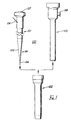
- FIG.1 Depicted in FIG.1 is a preferred illustrative embodiment of medical device 100 for percutaneously accessing a body cavity for an endoscopic surgical procedure.
- the medical access device comprises dilator 101, outer sheath 102, and inner sheath 103.
- Dilator 101 is positioned in the hollow passageway of outer sheath 102 and percutaneously inserted into a body cavity via wire guide 104.
- the device 101 dilates rather than cuts the patient.
- the surgeon introduces an introducer needle into the peritoneal body cavity via the umbilicus.
- the peritoneal cavity is typically insufflated with a gas such as carbon dioxide, and the wire guide 104 is inserted into the insufflated body cavity via the puncture site formed by the introducer needle.
- Dilator 101 is inserted into outer sheath 102 and placed overwire guide 104.
- the puncture site is dilated, and the dilator and outer sheath are introduced into the insufflated peritoneal cavity by applying a force to end cap 107 of the dilator.
- the dilation of the puncture site is enhanced by first wetting hydrophilic material 105 coating the conically-shaped distal end 106 of the dilator.
- the dilator and wire guide are removed through the outer sheath positioned in the body cavity, and the inner sheath 103 is positioned in the passageway of the outer sheath. Insufflation of the body cavity is maintained through side ports 108 laterally positioned about the proximal end of the inner access sheath.
- FIG.2 Depicted in FIG.2 is a cross-sectional view of dilator 101 with wire guide 104 extending through passageway 112.
- Dilator 101 comprises an elongated member 109 having a conically-tapered distal end 106, proximal end 110, and outside lateral wall 111 extending between the two ends.
- Hollow passageway 112 extends longitudinally in the elongated member and opens distally from the tapered distal end at opening 113 and laterally from the outside lateral wall about the proximal end.
- Passageway 112 is sized for extending wire guide 104 therethrough as shown.
- End cap 107 is positioned at and extends from proximal end 110 of the elongated member.
- the dilator also includes a well-known hydrophilic material 105 coating the tapered distal end, which is wetted with, for example, saline to ease dilation of the puncture site.
- the elongated member further includes shoulder 114 positioned about the proximal end of the elongated member, which is sized for abutting against the proximal end of outer sheath 102. Shoulder 114 fixedly positions the dilator against the proximal end of outer sheath 102 when the dilator and outer sheath are being introduced into the peritoneal body cavity via the puncture site.
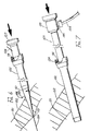
- FIG.3 Depicted in FIG.3 is another aspect of dilator 101 including a first elongated member 156 having conically-tapered distal end 106, proximal end 110, and side lateral wall 115 extending between the two ends. Hollow passageway 116 extends longitudinally between ends 106 and 110.
- the dilator further includes a second elongated member 117 positioned within passageway 116 and having a passageway 118 opening from conically-tapered distal end 106 distally and from side lateral wall 115 laterally about proximal end 110.
- End cap 107 is attached and extends from the proximal end of first elongated member 156 via sleeve 119.
- Sleeve 119 is attached about the proximal end 110 of the first member and to the end cap and has a lateral opening 120 communicating with the passageway of elongated member 117.
- First and second elongated members 156 and 117 are comprised of a well-known rigid, thermoplastic material such as polyvinylchloride having a durometer of approximately 90 on the Shore A scale.
- Elongated member 156 comprises a 38 French polyvinylchloride tube approximately 25cms in length.
- Second member tube 117 comprises a 28 French polyvinylchloride tube also approximately 25cms in length.
- the second member tube is inserted in passageway 116 of the first member tube with a mandril inserted into passageway 118 of the second tube.
- the two distal ends are heated to melt the two distal ends together to form conically-tapered distal end 106 approximately 5cms in length.
- the proximal end of the inner member tube is glued to the outside lateral wall about the proximal end of the outer member tube.
- Polyvinylchloride sleeve 119 is placed over the proximal end of the outer member tube attached thereto using a well-known medical grade adhesive.
- Opening 120 is formed in the sleeve to permit communication with passage 118 of the inner member tube.
- the opening and inner member passageway are large enough to permit a commercially available wire guide having, for example, a 0.0965cms (0.038”) outer diameter to pass readily therethrough.
- End cap 107 is a circular knob having an outer diameter of approximately 25mms and a length of approximately the same dimension which is inserted into the opening of the sleeve and attached thereto using again, for example, medical grade adhesive.
- a well-known hydrophilic material 105 coats the conically-tapered distal end of the dilator.
- the dilator depicted in FIG.2 is comprised of, for example, the same thermoplastic polyvinylchloride material having approximately the same dimensions as the dilator of FIG.3.
- Outer sheath 102 comprises a well-known thermoplastic material tube 121 such as polytetrafluoroethylene having a slick outer surface. This thermoplastic material is also a rigid thermoplastic having a durometer of approximately 90 on the Shore A scale. Tube 121 has a tapered distal end 122, a flared proximal end 123 at the opposite ends of the passageway 124 extending longitudinally through the tube. The outer sheath tube is approximately 15cms in length and has an inner diameter of 38 French to position dilator 101 therethrough. Fitting 125 is attached to proximal end 123 of the outer sheath tube.
- Fitting 125 is attached to proximal end 123 of the outer sheath tube.
- Fitting 125 is comprised of three acetal polymer components 126,127, and 128.
- Circular T-shaped sleeve 127 with annular rings 129 and 130 is pushed into flared proximal end 123.
- Lock ring 126 is press-fitted over the outside of flared proximal end 123 to attach fitting 125 to inner sheath tubing 121.
- Beveled annular end cap 128 is positioned as shown to fit over the T-shaped sleeve 127 to position silicon material seal 131 therebetween.
- Well-known medical grade adhesive affixes beveled end cap 128 to T-shaped sleeve 127.
- Silicon material seal 131 has an approximate 9mms aperture 132 therein which seals against the outside lateral wall of dilator 101 when the dilator is inserted into passageway 124 of the outer sheath.
- the proximal end of sleeve 119 engages the silicon seal and abuts against edge 133 of the T-shaped sleeve 127. This fixedly positions the outer sleeve with respect to dilator 101.
- shoulder 114 also abuts against seal 131 and passage 133 of the T-shaped sleeve, again to affix the relative position of the dilator with respect to the outer sheath.
- the polytetrafluoroethylene material of the outer sleeve tube has a slick surface 134 for engaging and sliding through the dilated puncture site when distal end 122 comes in contact therewith.
- inner sheath 103 of FIG.1 Depicted in FIG.5 is inner sheath 103 of FIG.1.
- the inner sheath is approximately 15cms in overall length and comprises an optically clear, very rigid thermoplastic material tube 135 having an extremely high durometer.
- a thermoplastic material is cellulose acetate butyrate.
- Inner sheath tube 135 is approximately 15.5cms in length and has an outer diameter of 1.262cms (0.497") and an inner diameter of 1.08cms (0.426").
- the inner sheath tube has a tapered distal end 136 and a proximal end 137 at opposite ends of hollow passageway 138 extending longitudinally in the tube.
- the sheath is sized for positioning within the passageway of outer sheath 102 and has a hollow passageway sized to permit the use of endoscopic instruments up to 10mms in diameter.
- the inner sheath also includes shoulder piece 139 having a distal neck 140 that is positioned into the proximal end 137 of the inner sheath tube. Medical grade adhesive 141 and 142 are utilized to cement the two pieces together.
- the larger diameter shoulder 143 is positioned about the proximal end of the inner sheath and is sized for abutting against the proximal end of the outer sheath.
- Passageway 138 extends through shoulder piece 139.
- Side port 144 laterally extends from the shoulder piece and communicates with passageway 138.
- the port is flanged for securing a Luer lock fitting of an insufflating line thereto.
- First seal 145 is positioned at the proximal end of the shoulder piece and includes criss-crossed slits 146 and 147 for permitting passage of endoscopic instruments therethrough and forming a seal thereabout. These slits communicate with passageway 138 of the inner sheath.
- the second flexible seal 148 is also attached about the proximal end of the shoulder piece and has an aperture 149 formed therein adjacent to the criss-crossed slits for positioning endoscopic instruments placed therethrough. The aperture is positioned against the slits to further facilitate a gas-tight seal against endoscopic instruments inserted therethrough.
- the second seal is attached to the proximal end of the shoulder piece with a polyethylene shrink tube 150 as shown.
- FIGs.6-8 Depicted in FIGs.6-8 is the method of percutaneously placing outer and inner access sheaths 102 and 103 into body cavity 151 through abdominal wall 152 with the use of wire guide 104 and dilator 101.
- the method comprises introducing wire guide 104 percutaneously into body cavity 151 through puncture site 153 as depicted in FIG.6.
- Dilator 101 is positioned into the passageway of outer sheath 102 with shoulder 114 abutting against the proximal end of the outer sheath.
- the dilator and outer sheath are placed over wire guide 104 and inserted into the puncture site.
- Tapered distal end 106 dilates the puncture site as a force is applied to end cap 107 of the dilator.
- Saline is applied to wet hydrophilic material 105 coating the tapered distal end.
- the conically-shaped distal ends dilate the puncture site atraumatically to the diameter of the dilator and outer shea
- inner sheath 103 is inserted through passageway 124 of outer sheath 102.
- the inner sheath is introduced into the body cavity by way of the outer sheath with seal 131 positioned at the proximal end of the outer sheath preventing the escape of insufflating gas from body cavity 151.
- a supply line 154 is attached to side port 144 of the inner sheath to supply the peritoneal body cavity with carbon dioxide gas for maintaining insufflation of the body cavity.
- endoscope 155 is introduced through the innersheath through seals 145 and 148 into the peritoneal cavity for providing a viewing space through which the surgeon can view the cavity during a surgical procedure.
- One or more of these inner and outer access sheaths may be used to penetrate the peritoneal body cavity to permit the surgeon to introduce other endoscopic surgical instruments to perform a particular procedure.
- the inner sheath may also be removed from the outer sheath to permit larger pieces of tissue or organs to be removed directly through the outer sheath.
- the outer sheath may also include a side port having one or more seals at its proximal end for cooperating with the dilator to insert the outer sheath into a body cavity.
- the dilator would be removed and endoscopic surgical instruments inserted solely through the outer sheath with the seals and insufflating line attached to the proximal end thereof.
- This medical device would also be inserted using a wire guide percutaneously inserted into the cavity.
- the outer diameter of a modified device is also contemplated to be smaller to provide for endoscopic instrument introduction.
- the dilator passageway opens at the proximal end of the elongated member or end cap.
Abstract
Description
- This invention relates to medical devices for performing endoscopic surgery.
- It is desirable to perform minimally invasive endoscopic procedures that utilize percutaneous access sheaths such as a percutaneous cholecystec- tomy, or a percutaneous cholelithotomy.
- According to the present invention there is provided medical apparatus as defined in claim 1 or 2.
- The surgeon typically utilizes an introducer needle to access and insufflate the peritoneal cavity via the umbilicus. A wire guide is introduced through the needle, and the needle is removed, leaving the guide in place. The dilator advantageously includes a hollow passageway for the wire guide.
- The dilator passageway opens laterally from a shoulder to permit the wire guide to pass therefrom and not interfere with the surgeon's introduction of the access device.
-
- FIG.1 depicts the medical device of the present invention;
- FIG.2 depicts a cross-sectional view of one aspect of the dilator and wire guide of FIG.1;
- FIG.3 depicts a cross-sectional view of another aspect of the dilator of FIG.1;
- FIG.4 depicts a partial cross-sectional view of the outer access sheath of FIG.1;
- FIG.5 depicts a partial view of the inner access sheath of FIG.1; and
- FIGs.6-8 depict the method of percutaneously placing the inner and outer access sheaths of FIG.1 into a body cavity.
- Depicted in FIG.1 is a preferred illustrative embodiment of
medical device 100 for percutaneously accessing a body cavity for an endoscopic surgical procedure. The medical access device comprisesdilator 101,outer sheath 102, andinner sheath 103. Dilator 101 is positioned in the hollow passageway ofouter sheath 102 and percutaneously inserted into a body cavity viawire guide 104. Thedevice 101 dilates rather than cuts the patient. By way of example, the surgeon introduces an introducer needle into the peritoneal body cavity via the umbilicus. The peritoneal cavity is typically insufflated with a gas such as carbon dioxide, and thewire guide 104 is inserted into the insufflated body cavity via the puncture site formed by the introducer needle. Dilator 101 is inserted intoouter sheath 102 and placedoverwire guide 104. The puncture site is dilated, and the dilator and outer sheath are introduced into the insufflated peritoneal cavity by applying a force to endcap 107 of the dilator. The dilation of the puncture site is enhanced by first wettinghydrophilic material 105 coating the conically-shapeddistal end 106 of the dilator. The dilator and wire guide are removed through the outer sheath positioned in the body cavity, and theinner sheath 103 is positioned in the passageway of the outer sheath. Insufflation of the body cavity is maintained throughside ports 108 laterally positioned about the proximal end of the inner access sheath. - Depicted in FIG.2 is a cross-sectional view of
dilator 101 withwire guide 104 extending throughpassageway 112.Dilator 101 comprises anelongated member 109 having a conically-tapereddistal end 106,proximal end 110, and outside lateral wall 111 extending between the two ends.Hollow passageway 112 extends longitudinally in the elongated member and opens distally from the tapered distal end at opening 113 and laterally from the outside lateral wall about the proximal end. Passageway 112 is sized for extendingwire guide 104 therethrough as shown.End cap 107 is positioned at and extends fromproximal end 110 of the elongated member. This end cap fits easily into the palm of the surgeon's hand or is easily grasped by the fingers to apply force to the dilator for introducing the tapered distal end into the puncture site overwire guide 104. The dilator also includes a well-knownhydrophilic material 105 coating the tapered distal end, which is wetted with, for example, saline to ease dilation of the puncture site. The elongated member further includesshoulder 114 positioned about the proximal end of the elongated member, which is sized for abutting against the proximal end ofouter sheath 102.Shoulder 114 fixedly positions the dilator against the proximal end ofouter sheath 102 when the dilator and outer sheath are being introduced into the peritoneal body cavity via the puncture site. - Depicted in FIG.3 is another aspect of
dilator 101 including a firstelongated member 156 having conically-tapereddistal end 106,proximal end 110, and side lateral wall 115 extending between the two ends. Hollow passageway 116 extends longitudinally betweenends passageway 118 opening from conically-tapereddistal end 106 distally and from side lateral wall 115 laterally aboutproximal end 110.End cap 107 is attached and extends from the proximal end of firstelongated member 156 viasleeve 119. Sleeve 119 is attached about theproximal end 110 of the first member and to the end cap and has alateral opening 120 communicating with the passageway of elongated member 117. - First and second
elongated members 156 and 117 are comprised of a well-known rigid, thermoplastic material such as polyvinylchloride having a durometer of approximately 90 on the Shore A scale. Elongatedmember 156 comprises a 38 French polyvinylchloride tube approximately 25cms in length. Second member tube 117 comprises a 28 French polyvinylchloride tube also approximately 25cms in length. The second member tube is inserted in passageway 116 of the first member tube with a mandril inserted intopassageway 118 of the second tube. The two distal ends are heated to melt the two distal ends together to form conically-tapereddistal end 106 approximately 5cms in length. The proximal end of the inner member tube is glued to the outside lateral wall about the proximal end of the outer member tube.Polyvinylchloride sleeve 119 is placed over the proximal end of the outer member tube attached thereto using a well-known medical grade adhesive.Opening 120 is formed in the sleeve to permit communication withpassage 118 of the inner member tube. The opening and inner member passageway are large enough to permit a commercially available wire guide having, for example, a 0.0965cms (0.038") outer diameter to pass readily therethrough.End cap 107 is a circular knob having an outer diameter of approximately 25mms and a length of approximately the same dimension which is inserted into the opening of the sleeve and attached thereto using again, for example, medical grade adhesive. A well-knownhydrophilic material 105 coats the conically-tapered distal end of the dilator. - The dilator depicted in FIG.2 is comprised of, for example, the same thermoplastic polyvinylchloride material having approximately the same dimensions as the dilator of FIG.3.
- Depicted in FIG.4 is
outer sheath 102 of FIG.1.Outer sheath 102 comprises a well-knownthermoplastic material tube 121 such as polytetrafluoroethylene having a slick outer surface. This thermoplastic material is also a rigid thermoplastic having a durometer of approximately 90 on the Shore A scale. Tube 121 has a tapereddistal end 122, a flaredproximal end 123 at the opposite ends of thepassageway 124 extending longitudinally through the tube. The outer sheath tube is approximately 15cms in length and has an inner diameter of 38 French to positiondilator 101 therethrough. Fitting 125 is attached toproximal end 123 of the outer sheath tube. Fitting 125 is comprised of three acetal polymer components 126,127, and 128. Circular T-shaped sleeve 127 withannular rings 129 and 130 is pushed into flaredproximal end 123.Lock ring 126 is press-fitted over the outside of flaredproximal end 123 to attach fitting 125 toinner sheath tubing 121. Beveledannular end cap 128 is positioned as shown to fit over the T-shaped sleeve 127 to positionsilicon material seal 131 therebetween. Well-known medical grade adhesive affixes beveledend cap 128 to T-shaped sleeve 127.Silicon material seal 131 has anapproximate 9mms aperture 132 therein which seals against the outside lateral wall ofdilator 101 when the dilator is inserted intopassageway 124 of the outer sheath. When inserted therein, the proximal end ofsleeve 119 engages the silicon seal and abuts againstedge 133 of the T-shaped sleeve 127. This fixedly positions the outer sleeve with respect todilator 101. Likewiseshoulder 114 also abuts againstseal 131 andpassage 133 of the T-shaped sleeve, again to affix the relative position of the dilator with respect to the outer sheath. The polytetrafluoroethylene material of the outer sleeve tube has aslick surface 134 for engaging and sliding through the dilated puncture site whendistal end 122 comes in contact therewith. - Depicted in FIG.5 is
inner sheath 103 of FIG.1. The inner sheath is approximately 15cms in overall length and comprises an optically clear, very rigidthermoplastic material tube 135 having an extremely high durometer. Such a thermoplastic material is cellulose acetate butyrate.Inner sheath tube 135 is approximately 15.5cms in length and has an outer diameter of 1.262cms (0.497") and an inner diameter of 1.08cms (0.426"). The inner sheath tube has a tapereddistal end 136 and aproximal end 137 at opposite ends ofhollow passageway 138 extending longitudinally in the tube. The sheath is sized for positioning within the passageway ofouter sheath 102 and has a hollow passageway sized to permit the use of endoscopic instruments up to 10mms in diameter. The inner sheath also includesshoulder piece 139 having adistal neck 140 that is positioned into theproximal end 137 of the inner sheath tube. Medical grade adhesive 141 and 142 are utilized to cement the two pieces together. The larger diameter shoulder 143 is positioned about the proximal end of the inner sheath and is sized for abutting against the proximal end of the outer sheath.Passageway 138 extends throughshoulder piece 139.Side port 144 laterally extends from the shoulder piece and communicates withpassageway 138. The port is flanged for securing a Luer lock fitting of an insufflating line thereto.First seal 145 is positioned at the proximal end of the shoulder piece and includes criss-crossedslits passageway 138 of the inner sheath. The secondflexible seal 148 is also attached about the proximal end of the shoulder piece and has anaperture 149 formed therein adjacent to the criss-crossed slits for positioning endoscopic instruments placed therethrough. The aperture is positioned against the slits to further facilitate a gas-tight seal against endoscopic instruments inserted therethrough. The second seal is attached to the proximal end of the shoulder piece with apolyethylene shrink tube 150 as shown. - Depicted in FIGs.6-8 is the method of percutaneously placing outer and
inner access sheaths body cavity 151 throughabdominal wall 152 with the use ofwire guide 104 anddilator 101. The method comprises introducingwire guide 104 percutaneously intobody cavity 151 throughpuncture site 153 as depicted in FIG.6.Dilator 101 is positioned into the passageway ofouter sheath 102 withshoulder 114 abutting against the proximal end of the outer sheath. The dilator and outer sheath are placed overwire guide 104 and inserted into the puncture site. Tapereddistal end 106 dilates the puncture site as a force is applied to endcap 107 of the dilator. Saline is applied to wethydrophilic material 105 coating the tapered distal end. The conically-shaped distal ends dilate the puncture site atraumatically to the diameter of the dilator and outer sheath. - Force is continually applied to end
cap 107 to fully dilatepuncture site 153 to the outer diameters ofdilator 101 andsheath 102. When the dilator and the distal end of the outer sheath are positioned inbody cavity 151 through the abdominal wall and puncture site, the dilator and wire guide are removed from the body cavity through the outer sheath. - After the wire guide and dilator are removed from the passageway of the outer sheath,
inner sheath 103 is inserted throughpassageway 124 ofouter sheath 102. The inner sheath is introduced into the body cavity by way of the outer sheath withseal 131 positioned at the proximal end of the outer sheath preventing the escape of insufflating gas frombody cavity 151. Typically, asupply line 154 is attached toside port 144 of the inner sheath to supply the peritoneal body cavity with carbon dioxide gas for maintaining insufflation of the body cavity. - When the inner sheath is fully inserted into the outer sheath,
shoulder piece 139 abuts against the proximal end of outer sheath fitting 125 as depicted in FIG.8. The distal end of the inner sheath will typically extend a short distance about the distal end of the outer sheath. When so positioned, seals 145 and 148 of the inner sheath along with the seal at the proximal end of outer sheath prevent the escape of insufflating gas from the body cavity.Insufflating gas line 154 also continues to supply insufflation gas to theperitoneal body cavity 151. As shown,endoscope 155 is introduced through the innersheath throughseals - It is contemplated that the outer sheath may also include a side port having one or more seals at its proximal end for cooperating with the dilator to insert the outer sheath into a body cavity. The dilator would be removed and endoscopic surgical instruments inserted solely through the outer sheath with the seals and insufflating line attached to the proximal end thereof. This medical device would also be inserted using a wire guide percutaneously inserted into the cavity. The outer diameter of a modified device is also contemplated to be smaller to provide for endoscopic instrument introduction. It is further contemplated that the dilator passageway opens at the proximal end of the elongated member or end cap.
Claims (11)
Applications Claiming Priority (2)
| Application Number | Priority Date | Filing Date | Title |
|---|---|---|---|
| US592676 | 1990-10-03 | ||
| US07/592,676 US5112308A (en) | 1990-10-03 | 1990-10-03 | Medical device for and a method of endoscopic surgery |
Publications (3)
| Publication Number | Publication Date |
|---|---|
| EP0479565A2 true EP0479565A2 (en) | 1992-04-08 |
| EP0479565A3 EP0479565A3 (en) | 1992-07-01 |
| EP0479565B1 EP0479565B1 (en) | 1995-12-20 |
Family
ID=24371627
Family Applications (1)
| Application Number | Title | Priority Date | Filing Date |
|---|---|---|---|
| EP91309012A Expired - Lifetime EP0479565B1 (en) | 1990-10-03 | 1991-10-02 | Medical apparatus for endoscopic surgery |
Country Status (6)
| Country | Link |
|---|---|
| US (1) | US5112308A (en) |
| EP (1) | EP0479565B1 (en) |
| JP (1) | JPH04263870A (en) |
| AU (1) | AU648341B2 (en) |
| CA (1) | CA2052541A1 (en) |
| DE (1) | DE69115626D1 (en) |
Cited By (13)
| Publication number | Priority date | Publication date | Assignee | Title |
|---|---|---|---|---|
| EP0604197A2 (en) * | 1992-12-22 | 1994-06-29 | Ethicon, Inc. | Safety trocar |
| EP0647434A2 (en) * | 1993-10-08 | 1995-04-12 | United States Surgical Corporation | Tissue piercing members |
| EP0723416A1 (en) * | 1993-10-08 | 1996-07-31 | Heartport, Inc. | Stereoscopic percutaneous visualization system |
| US5554137A (en) * | 1993-10-08 | 1996-09-10 | United States Surgical Corporation | Tissue piercing members |
| EP0745353A1 (en) * | 1995-06-01 | 1996-12-04 | Sandoz Nutrition Ltd. | Gastrostomy tube removal tool |
| US5957832A (en) * | 1993-10-08 | 1999-09-28 | Heartport, Inc. | Stereoscopic percutaneous visualization system |
| FR2810531A1 (en) * | 2000-06-22 | 2001-12-28 | Richard Cancel | Trocar for surgery has injection moulded plastics tip and body for perforator moving in sleeve |
| WO2005023359A1 (en) * | 2003-08-29 | 2005-03-17 | Medtronic, Inc. | Percutaneous flat lead introducer |
| US7331971B2 (en) | 2003-10-31 | 2008-02-19 | Olympus Corporation | Living-body tissue removing apparatus |
| US7662164B2 (en) | 2003-10-31 | 2010-02-16 | Olympus Corporation | Living-body tissue removing apparatus |
| US8105231B2 (en) * | 2003-10-31 | 2012-01-31 | Olympus Corporation | Living-body tissue removing apparatus |
| US9084872B2 (en) | 2005-06-09 | 2015-07-21 | Medtronic, Inc. | Introducer for therapy delivery elements |
| EP2368594B1 (en) * | 1999-04-30 | 2016-02-17 | Applied Medical Resources Corporation | Ureteral access sheath |
Families Citing this family (77)
| Publication number | Priority date | Publication date | Assignee | Title |
|---|---|---|---|---|
| US5395342A (en) | 1990-07-26 | 1995-03-07 | Yoon; Inbae | Endoscopic portal |
| US5211650A (en) * | 1991-01-07 | 1993-05-18 | Laparomed Corporation | Dual function suturing device and method |
| US5320629B1 (en) * | 1991-01-07 | 2000-05-02 | Advanced Surgical Inc | Device and method for applying suture |
| US5735290A (en) | 1993-02-22 | 1998-04-07 | Heartport, Inc. | Methods and systems for performing thoracoscopic coronary bypass and other procedures |
| US5209736A (en) * | 1991-10-18 | 1993-05-11 | Ethicon, Inc. | Trocar method and apparatus |
| US5545142A (en) * | 1991-10-18 | 1996-08-13 | Ethicon, Inc. | Seal members for surgical trocars |
| US5230705A (en) * | 1992-03-13 | 1993-07-27 | Wilk Peter J | Method of intravenous catheterization device |
| US5246424A (en) * | 1992-03-13 | 1993-09-21 | Wilk Peter J | Device and method for use in obtaining access to an internal body organ |
| US6494211B1 (en) | 1993-02-22 | 2002-12-17 | Hearport, Inc. | Device and methods for port-access multivessel coronary artery bypass surgery |
| US5342315A (en) * | 1993-04-12 | 1994-08-30 | Ethicon, Inc. | Trocar seal/protector assemblies |
| US6629984B1 (en) | 1998-07-07 | 2003-10-07 | Kwan-Ho Chan | Surgical repair kit and its method of use |
| US5509908A (en) * | 1994-04-21 | 1996-04-23 | Novoste Corporation | Angular sheath introducer |
| US5545150A (en) * | 1994-05-06 | 1996-08-13 | Endoscopic Concepts, Inc. | Trocar |
| US5749889A (en) * | 1996-02-13 | 1998-05-12 | Imagyn Medical, Inc. | Method and apparatus for performing biopsy |
| US5906595A (en) * | 1997-04-25 | 1999-05-25 | Ethicon Endo-Surgery, Inc. | Trocar having protector with flexible end and improved seal assembly |
| US5779697A (en) * | 1997-05-28 | 1998-07-14 | Linvatec Corporation | Arthroscopic cannula with fluid seals |
| US6030364A (en) * | 1997-10-03 | 2000-02-29 | Boston Scientific Corporation | Apparatus and method for percutaneous placement of gastro-intestinal tubes |
| US6767356B2 (en) * | 2000-09-01 | 2004-07-27 | Angiolink Corporation | Advanced wound site management systems and methods |
| US8551134B2 (en) * | 2000-09-01 | 2013-10-08 | Medtronic Vascular, Inc. | Wound site management and wound closure device |
| US20020177847A1 (en) * | 2001-03-30 | 2002-11-28 | Long Gary L. | Endoscopic ablation system with flexible coupling |
| US6918906B2 (en) * | 2001-03-30 | 2005-07-19 | Gary L. Long | Endoscopic ablation system with improved electrode geometry |
| US20030181900A1 (en) * | 2002-03-25 | 2003-09-25 | Long Gary L. | Endoscopic ablation system with a plurality of electrodes |
| US7097644B2 (en) * | 2001-03-30 | 2006-08-29 | Ethicon Endo-Surgery, Inc. | Medical device with improved wall construction |
| US7137981B2 (en) * | 2002-03-25 | 2006-11-21 | Ethicon Endo-Surgery, Inc. | Endoscopic ablation system with a distally mounted image sensor |
| CN101574306B (en) * | 2003-04-28 | 2012-12-26 | 住友电木株式会社 | Catheter kit for burrow |
| JP4444209B2 (en) * | 2003-04-28 | 2010-03-31 | 裕 鈴木 | Fistula catheter kit |
| US7811303B2 (en) * | 2003-08-26 | 2010-10-12 | Medicine Lodge Inc | Bodily tissue dilation systems and methods |
| US9241735B2 (en) | 2003-12-05 | 2016-01-26 | Onset Medical Corporation | Expandable percutaneous sheath |
| US7585290B2 (en) * | 2004-01-20 | 2009-09-08 | Ethicon Endo-Surgery, Inc. | Medical device for providing access |
| US20060041270A1 (en) * | 2004-05-07 | 2006-02-23 | Jay Lenker | Medical access sheath |
| JP2008511341A (en) * | 2004-05-28 | 2008-04-17 | ユー.エス. エンドスコピー グループ, インコーポレイテッド | Overtube assembly |
| US8475476B2 (en) * | 2004-06-01 | 2013-07-02 | Cook Medical Technologies Llc | System and method for accessing a body cavity |
| US7232438B2 (en) | 2004-07-09 | 2007-06-19 | Ethicon Endo-Surgery, Inc. | Ablation device with clear probe |
| US20060135981A1 (en) * | 2004-09-09 | 2006-06-22 | Jay Lenker | Expandable transluminal sheath |
| US7892203B2 (en) | 2004-09-09 | 2011-02-22 | Onset Medical Corporation | Expandable transluminal sheath |
| US20060135962A1 (en) * | 2004-09-09 | 2006-06-22 | Kick George F | Expandable trans-septal sheath |
| WO2006069396A1 (en) * | 2004-12-21 | 2006-06-29 | Onset Medical Corporation | Non-expandable transluminal access sheath |
| US20060259061A1 (en) * | 2005-04-22 | 2006-11-16 | Kick George F | Expandable sheath for percutaneous upper gastrointestinal tract access |
| US8092481B2 (en) * | 2005-06-03 | 2012-01-10 | Onset Medical Corporation | Expandable percutaneous sheath |
| US20070005087A1 (en) * | 2005-06-30 | 2007-01-04 | Smith Robert C | Thin bladed obturator with curved surfaces |
| US8430851B2 (en) | 2005-10-14 | 2013-04-30 | Applied Medical Resources Corporation | Surgical access port |
| US8690831B2 (en) | 2008-04-25 | 2014-04-08 | Ethicon Endo-Surgery, Inc. | Gas jet fluid removal in a trocar |
| US8579807B2 (en) | 2008-04-28 | 2013-11-12 | Ethicon Endo-Surgery, Inc. | Absorbing fluids in a surgical access device |
| US8915842B2 (en) * | 2008-07-14 | 2014-12-23 | Ethicon Endo-Surgery, Inc. | Methods and devices for maintaining visibility and providing irrigation and/or suction during surgical procedures |
| WO2008079828A2 (en) | 2006-12-20 | 2008-07-03 | Onset Medical Corporation | Expandable trans-septal sheath |
| WO2008092029A2 (en) | 2007-01-24 | 2008-07-31 | Access Scientific, Inc. | Access device |
| JP2010524586A (en) * | 2007-04-18 | 2010-07-22 | アクセス サイエンティフィック、インク. | Approach device |
| EP2152348B1 (en) | 2007-04-18 | 2015-02-25 | Access Scientific, Inc. | Access device |
| US20080319467A1 (en) * | 2007-06-22 | 2008-12-25 | Thomas Wenchell | Thin bladed obturator |
| DE102007040358A1 (en) * | 2007-08-27 | 2009-03-05 | Technische Universität München | Trocar tube, trocar, obturator or rectoscope for transluminal endoscopic surgery over natural orifices |
| CA2718496A1 (en) * | 2008-03-14 | 2009-09-17 | Access Scientific, Inc. | Access device |
| US8636686B2 (en) | 2008-04-28 | 2014-01-28 | Ethicon Endo-Surgery, Inc. | Surgical access device |
| USD700326S1 (en) | 2008-04-28 | 2014-02-25 | Ethicon Endo-Surgery, Inc. | Trocar housing |
| US11235111B2 (en) | 2008-04-28 | 2022-02-01 | Ethicon Llc | Surgical access device |
| US8870747B2 (en) * | 2008-04-28 | 2014-10-28 | Ethicon Endo-Surgery, Inc. | Scraping fluid removal in a surgical access device |
| US8568362B2 (en) * | 2008-04-28 | 2013-10-29 | Ethicon Endo-Surgery, Inc. | Surgical access device with sorbents |
| US8273060B2 (en) * | 2008-04-28 | 2012-09-25 | Ethicon Endo-Surgery, Inc. | Fluid removal in a surgical access device |
| US9358041B2 (en) | 2008-04-28 | 2016-06-07 | Ethicon Endo-Surgery, Llc | Wicking fluid management in a surgical access device |
| US20090270686A1 (en) * | 2008-04-29 | 2009-10-29 | Ethicon Endo-Surgery, Inc. | Methods and devices for maintaining visibility during surgical procedures |
| US7981092B2 (en) | 2008-05-08 | 2011-07-19 | Ethicon Endo-Surgery, Inc. | Vibratory trocar |
| US20110202006A1 (en) * | 2008-10-22 | 2011-08-18 | Access Scientific, Inc. | Access device |
| CA2743578A1 (en) * | 2008-11-12 | 2010-05-20 | Access Scientific, Inc. | Access device |
| JP2012513292A (en) | 2008-12-23 | 2012-06-14 | シルク・ロード・メディカル・インコーポレイテッド | Method and system for treating acute ischemic stroke |
| AU2011213558A1 (en) | 2010-02-08 | 2012-09-27 | Access Scientific, Inc. | Access device |
| US8603124B1 (en) | 2010-11-23 | 2013-12-10 | Robert Hatch | Modified surgical scalpel with polyurethane mated sheath for ultrasound assisted carpal tunnel surgery |
| US9566087B2 (en) | 2013-03-15 | 2017-02-14 | Access Scientific, Llc | Vascular access device |
| US9265512B2 (en) | 2013-12-23 | 2016-02-23 | Silk Road Medical, Inc. | Transcarotid neurovascular catheter |
| USD753290S1 (en) | 2014-03-03 | 2016-04-05 | The Spectranetics Corporation | Sheath set |
| USD753289S1 (en) | 2014-03-03 | 2016-04-05 | The Spectranetics Corporation | Sheath |
| US9675371B2 (en) | 2014-03-03 | 2017-06-13 | The Spectranetics Corporation | Dilator sheath set |
| US9241699B1 (en) | 2014-09-04 | 2016-01-26 | Silk Road Medical, Inc. | Methods and devices for transcarotid access |
| US11027104B2 (en) | 2014-09-04 | 2021-06-08 | Silk Road Medical, Inc. | Methods and devices for transcarotid access |
| WO2016176065A1 (en) | 2015-04-30 | 2016-11-03 | Access Scientific, Llc | Vascular access device |
| EP4233977A3 (en) * | 2015-05-13 | 2023-10-04 | AtriCure, Inc. | Access visualization systems |
| US11413427B2 (en) | 2018-02-08 | 2022-08-16 | Pacesetter, Inc. | Introducer hub assembly having cross-slit seal |
| US10569059B2 (en) | 2018-03-01 | 2020-02-25 | Asspv, Llc | Guidewire retention device |
| WO2023157440A1 (en) * | 2022-02-15 | 2023-08-24 | テルモ株式会社 | Dilator, catheter assembly, and method for operating catheter assembly |
Citations (6)
| Publication number | Priority date | Publication date | Assignee | Title |
|---|---|---|---|---|
| DE836546C (en) * | 1950-12-10 | 1952-04-15 | Josef Berchtold | Trocar to open deep abscesses or disintegrated cavities |
| US3994287A (en) * | 1974-07-01 | 1976-11-30 | Centre De Recherche Industrielle Du Quebec | Trocar |
| US4498902A (en) * | 1982-11-13 | 1985-02-12 | Purdue Research Foundation | Catheter guide |
| EP0206553A1 (en) * | 1985-05-30 | 1986-12-30 | Steven Streatfield Gill. | An expansible cannula |
| EP0339945A2 (en) * | 1988-04-25 | 1989-11-02 | Edwin L. Adair | Gas insufflation needle with instrument port |
| JPH02144070A (en) * | 1988-11-25 | 1990-06-01 | Toray Ind Inc | Easily slidable medical material |
Family Cites Families (14)
| Publication number | Priority date | Publication date | Assignee | Title |
|---|---|---|---|---|
| US3313299A (en) * | 1964-02-05 | 1967-04-11 | Richard G Spademan | Intravascular catheter with coaxial puncturing means |
| US4096860A (en) * | 1975-10-08 | 1978-06-27 | Mclaughlin William F | Dual flow encatheter |
| US4261357A (en) * | 1979-01-29 | 1981-04-14 | Critikon, Inc. | Catheter assembly for intermittent intravenous medicament delivery |
| SE426023B (en) * | 1981-04-23 | 1982-12-06 | Bengt Gustavsson | DEVICE BLA FOR INFANTRY OF CATHEDRES IN BLOOD BLOOD |
| JPS60234671A (en) * | 1984-05-09 | 1985-11-21 | テルモ株式会社 | Catheter inserter |
| US4729914A (en) * | 1985-12-30 | 1988-03-08 | Tyndale Plains-Hunter Ltd. | Hydrophilic coating and substrate coated therewith |
| GB2194890A (en) * | 1986-09-12 | 1988-03-23 | Boc Group Plc | Cannula assembly |
| DE3863680D1 (en) * | 1987-05-04 | 1991-08-22 | Vorwerk Co Interholding | ELECTRIC VACUUM CLEANER. |
| JPS6431701U (en) * | 1987-08-20 | 1989-02-27 | ||
| US4954130A (en) * | 1988-01-20 | 1990-09-04 | William P. Waters | Catheter/heparin lock and method of using same |
| US4862891A (en) * | 1988-03-14 | 1989-09-05 | Canyon Medical Products | Device for sequential percutaneous dilation |
| US4935008A (en) * | 1988-07-20 | 1990-06-19 | Lewis Jr Ronald L | Double lumen introducing needle |
| US4950257A (en) * | 1988-09-15 | 1990-08-21 | Mallinckrodt, Inc. | Catheter introducer with flexible tip |
| US5041097A (en) * | 1990-02-26 | 1991-08-20 | Johnson Gerald W | Intravenous catheter fitting with protective end seal |
-
1990
- 1990-10-03 US US07/592,676 patent/US5112308A/en not_active Expired - Lifetime
-
1991
- 1991-09-30 CA CA002052541A patent/CA2052541A1/en not_active Abandoned
- 1991-10-02 DE DE69115626T patent/DE69115626D1/en not_active Expired - Lifetime
- 1991-10-02 AU AU85530/91A patent/AU648341B2/en not_active Ceased
- 1991-10-02 EP EP91309012A patent/EP0479565B1/en not_active Expired - Lifetime
- 1991-10-03 JP JP3283708A patent/JPH04263870A/en active Pending
Patent Citations (6)
| Publication number | Priority date | Publication date | Assignee | Title |
|---|---|---|---|---|
| DE836546C (en) * | 1950-12-10 | 1952-04-15 | Josef Berchtold | Trocar to open deep abscesses or disintegrated cavities |
| US3994287A (en) * | 1974-07-01 | 1976-11-30 | Centre De Recherche Industrielle Du Quebec | Trocar |
| US4498902A (en) * | 1982-11-13 | 1985-02-12 | Purdue Research Foundation | Catheter guide |
| EP0206553A1 (en) * | 1985-05-30 | 1986-12-30 | Steven Streatfield Gill. | An expansible cannula |
| EP0339945A2 (en) * | 1988-04-25 | 1989-11-02 | Edwin L. Adair | Gas insufflation needle with instrument port |
| JPH02144070A (en) * | 1988-11-25 | 1990-06-01 | Toray Ind Inc | Easily slidable medical material |
Non-Patent Citations (1)
| Title |
|---|
| DERWENT WPIL, Derwent Publication Limited, London, GB; & JP-A-2 144 070 (PN) * |
Cited By (23)
| Publication number | Priority date | Publication date | Assignee | Title |
|---|---|---|---|---|
| EP0604197A3 (en) * | 1992-12-22 | 1995-01-25 | Ethicon Inc | Safety trocar. |
| EP0604197A2 (en) * | 1992-12-22 | 1994-06-29 | Ethicon, Inc. | Safety trocar |
| EP0647434A2 (en) * | 1993-10-08 | 1995-04-12 | United States Surgical Corporation | Tissue piercing members |
| EP0647434A3 (en) * | 1993-10-08 | 1995-10-18 | United States Surgical Corp | Tissue piercing members. |
| EP0723416A1 (en) * | 1993-10-08 | 1996-07-31 | Heartport, Inc. | Stereoscopic percutaneous visualization system |
| US5554167A (en) * | 1993-10-08 | 1996-09-10 | United States Surgical Corporation | Tissue piercing members |
| US5554137A (en) * | 1993-10-08 | 1996-09-10 | United States Surgical Corporation | Tissue piercing members |
| EP0723416A4 (en) * | 1993-10-08 | 1998-01-07 | Heartport Inc | Stereoscopic percutaneous visualization system |
| US5957832A (en) * | 1993-10-08 | 1999-09-28 | Heartport, Inc. | Stereoscopic percutaneous visualization system |
| US6508759B1 (en) * | 1993-10-08 | 2003-01-21 | Heartport, Inc. | Stereoscopic percutaneous visualization system |
| EP0745353A1 (en) * | 1995-06-01 | 1996-12-04 | Sandoz Nutrition Ltd. | Gastrostomy tube removal tool |
| EP2368594B1 (en) * | 1999-04-30 | 2016-02-17 | Applied Medical Resources Corporation | Ureteral access sheath |
| FR2810531A1 (en) * | 2000-06-22 | 2001-12-28 | Richard Cancel | Trocar for surgery has injection moulded plastics tip and body for perforator moving in sleeve |
| US8340779B2 (en) | 2003-08-29 | 2012-12-25 | Medtronic, Inc. | Percutaneous flat lead introducer |
| US8386052B2 (en) | 2003-08-29 | 2013-02-26 | Medtronic, Inc. | Percutaneous flat lead introducer |
| US8909353B2 (en) | 2003-08-29 | 2014-12-09 | Medtronic, Inc. | Percutaneous lead introducer |
| WO2005023359A1 (en) * | 2003-08-29 | 2005-03-17 | Medtronic, Inc. | Percutaneous flat lead introducer |
| US9687637B2 (en) | 2003-08-29 | 2017-06-27 | Medtronic, Inc. | Percutaneous flat lead introducer |
| US10173040B2 (en) | 2003-08-29 | 2019-01-08 | Medtronic, Inc. | Percutaneous flat lead introducer |
| US7331971B2 (en) | 2003-10-31 | 2008-02-19 | Olympus Corporation | Living-body tissue removing apparatus |
| US7662164B2 (en) | 2003-10-31 | 2010-02-16 | Olympus Corporation | Living-body tissue removing apparatus |
| US8105231B2 (en) * | 2003-10-31 | 2012-01-31 | Olympus Corporation | Living-body tissue removing apparatus |
| US9084872B2 (en) | 2005-06-09 | 2015-07-21 | Medtronic, Inc. | Introducer for therapy delivery elements |
Also Published As
| Publication number | Publication date |
|---|---|
| AU648341B2 (en) | 1994-04-21 |
| DE69115626D1 (en) | 1996-02-01 |
| US5112308A (en) | 1992-05-12 |
| CA2052541A1 (en) | 1992-04-04 |
| JPH04263870A (en) | 1992-09-18 |
| EP0479565B1 (en) | 1995-12-20 |
| EP0479565A3 (en) | 1992-07-01 |
| AU8553091A (en) | 1992-05-14 |
Similar Documents
| Publication | Publication Date | Title |
|---|---|---|
| EP0479565B1 (en) | Medical apparatus for endoscopic surgery | |
| US11123105B2 (en) | Visual insufflation port | |
| US5857999A (en) | Small diameter introducer for laparoscopic instruments | |
| CA1308619C (en) | Gas insufflation needle with instrument port | |
| US5630805A (en) | Method for accessing the peritoneal cavity | |
| US5137509A (en) | Surgical insufflation instrument | |
| US5176649A (en) | Insertion device for use with curved, rigid endoscopic instruments and the like | |
| US5454790A (en) | Method and apparatus for catheterization access | |
| US5290249A (en) | Surgical access sheath | |
| US5234455A (en) | Lipped cannula and methods of introducing surgical instruments in arthroscopic surgical procedures | |
| US4331138A (en) | Method of performing an emergency cricothyrotomy | |
| US5403264A (en) | Endoscopic closure inspection device | |
| US6451031B1 (en) | Blood vessel suturing device with single guide-wire/needle receiving lumen | |
| US5139487A (en) | Laparoscopic surgical instrument apparatus | |
| US6663605B2 (en) | Removable protective cannula for use in surgery | |
| US4291690A (en) | Means for performing an emergency cricothyrotomy | |
| AMERLINC et al. | A new laparoscopic method for implantation of peritoneal catheters | |
| CN111479526B (en) | Thin cannula trocar and method | |
| US11134983B1 (en) | Obturator and cannula for uterine and fetal surgeries | |
| AU2014268150B2 (en) | Visual insufflation obturator | |
| WO2008095270A1 (en) | Laparoscopic trocar with flexible endoscopic system | |
| IL101638A (en) | Microcannula | |
| JPH10146391A (en) | Apparatus for inserting catheter tube |
Legal Events
| Date | Code | Title | Description |
|---|---|---|---|
| PUAI | Public reference made under article 153(3) epc to a published international application that has entered the european phase |
Free format text: ORIGINAL CODE: 0009012 |
|
| AK | Designated contracting states |
Kind code of ref document: A2 Designated state(s): DE ES FR GB IT |
|
| PUAL | Search report despatched |
Free format text: ORIGINAL CODE: 0009013 |
|
| AK | Designated contracting states |
Kind code of ref document: A3 Designated state(s): DE ES FR GB IT |
|
| 17P | Request for examination filed |
Effective date: 19921001 |
|
| 17Q | First examination report despatched |
Effective date: 19931004 |
|
| GRAA | (expected) grant |
Free format text: ORIGINAL CODE: 0009210 |
|
| AK | Designated contracting states |
Kind code of ref document: B1 Designated state(s): DE ES FR GB IT |
|
| PG25 | Lapsed in a contracting state [announced via postgrant information from national office to epo] |
Ref country code: IT Free format text: LAPSE BECAUSE OF FAILURE TO SUBMIT A TRANSLATION OF THE DESCRIPTION OR TO PAY THE FEE WITHIN THE PRE;WARNING: LAPSES OF ITALIAN PATENTS WITH EFFECTIVE DATE BEFORE 2007 MAY HAVE OCCURRED AT ANY TIME BEFORE 2007. THE CORRECT EFFECTIVE DATE MAY BE DIFFERENT FROM THE ONE RECORDED.SCRIBED TIME-LIMIT Effective date: 19951220 Ref country code: ES Free format text: THE PATENT HAS BEEN ANNULLED BY A DECISION OF A NATIONAL AUTHORITY Effective date: 19951220 Ref country code: FR Effective date: 19951220 |
|
| REF | Corresponds to: |
Ref document number: 69115626 Country of ref document: DE Date of ref document: 19960201 |
|
| PG25 | Lapsed in a contracting state [announced via postgrant information from national office to epo] |
Ref country code: DE Effective date: 19960321 |
|
| EN | Fr: translation not filed | ||
| PLBE | No opposition filed within time limit |
Free format text: ORIGINAL CODE: 0009261 |
|
| STAA | Information on the status of an ep patent application or granted ep patent |
Free format text: STATUS: NO OPPOSITION FILED WITHIN TIME LIMIT |
|
| 26N | No opposition filed | ||
| REG | Reference to a national code |
Ref country code: GB Ref legal event code: IF02 |
|
| PGFP | Annual fee paid to national office [announced via postgrant information from national office to epo] |
Ref country code: GB Payment date: 20060915 Year of fee payment: 16 |
|
| GBPC | Gb: european patent ceased through non-payment of renewal fee |
Effective date: 20071002 |
|
| PG25 | Lapsed in a contracting state [announced via postgrant information from national office to epo] |
Ref country code: GB Free format text: LAPSE BECAUSE OF NON-PAYMENT OF DUE FEES Effective date: 20071002 |