EP0480298A2 - Filtration apparatus - Google Patents
Filtration apparatus Download PDFInfo
- Publication number
- EP0480298A2 EP0480298A2 EP91116825A EP91116825A EP0480298A2 EP 0480298 A2 EP0480298 A2 EP 0480298A2 EP 91116825 A EP91116825 A EP 91116825A EP 91116825 A EP91116825 A EP 91116825A EP 0480298 A2 EP0480298 A2 EP 0480298A2
- Authority
- EP
- European Patent Office
- Prior art keywords
- housing
- filter unit
- filtrate
- concentrate
- discharge opening
- Prior art date
- Legal status (The legal status is an assumption and is not a legal conclusion. Google has not performed a legal analysis and makes no representation as to the accuracy of the status listed.)
- Granted
Links
- 238000001914 filtration Methods 0.000 title claims abstract description 65
- 239000000706 filtrate Substances 0.000 claims abstract description 68
- 239000012141 concentrate Substances 0.000 claims abstract description 54
- 239000012528 membrane Substances 0.000 claims abstract description 29
- 238000007789 sealing Methods 0.000 claims description 7
- 238000010923 batch production Methods 0.000 claims 2
- 101100441413 Caenorhabditis elegans cup-15 gene Proteins 0.000 description 16
- 239000006193 liquid solution Substances 0.000 description 4
- 238000000034 method Methods 0.000 description 3
- 238000004140 cleaning Methods 0.000 description 1
- 230000001419 dependent effect Effects 0.000 description 1
- 239000012530 fluid Substances 0.000 description 1
- 239000007788 liquid Substances 0.000 description 1
- 238000011084 recovery Methods 0.000 description 1
- 238000013022 venting Methods 0.000 description 1
Images


Classifications
-
- B—PERFORMING OPERATIONS; TRANSPORTING
- B01—PHYSICAL OR CHEMICAL PROCESSES OR APPARATUS IN GENERAL
- B01D—SEPARATION
- B01D61/00—Processes of separation using semi-permeable membranes, e.g. dialysis, osmosis or ultrafiltration; Apparatus, accessories or auxiliary operations specially adapted therefor
- B01D61/14—Ultrafiltration; Microfiltration
- B01D61/18—Apparatus therefor
-
- B—PERFORMING OPERATIONS; TRANSPORTING
- B01—PHYSICAL OR CHEMICAL PROCESSES OR APPARATUS IN GENERAL
- B01D—SEPARATION
- B01D29/00—Filters with filtering elements stationary during filtration, e.g. pressure or suction filters, not covered by groups B01D24/00 - B01D27/00; Filtering elements therefor
- B01D29/11—Filters with filtering elements stationary during filtration, e.g. pressure or suction filters, not covered by groups B01D24/00 - B01D27/00; Filtering elements therefor with bag, cage, hose, tube, sleeve or like filtering elements
- B01D29/111—Making filtering elements
-
- B—PERFORMING OPERATIONS; TRANSPORTING
- B01—PHYSICAL OR CHEMICAL PROCESSES OR APPARATUS IN GENERAL
- B01D—SEPARATION
- B01D29/00—Filters with filtering elements stationary during filtration, e.g. pressure or suction filters, not covered by groups B01D24/00 - B01D27/00; Filtering elements therefor
- B01D29/39—Filters with filtering elements stationary during filtration, e.g. pressure or suction filters, not covered by groups B01D24/00 - B01D27/00; Filtering elements therefor with hollow discs side by side on, or around, one or more tubes, e.g. of the leaf type
-
- B—PERFORMING OPERATIONS; TRANSPORTING
- B01—PHYSICAL OR CHEMICAL PROCESSES OR APPARATUS IN GENERAL
- B01D—SEPARATION
- B01D29/00—Filters with filtering elements stationary during filtration, e.g. pressure or suction filters, not covered by groups B01D24/00 - B01D27/00; Filtering elements therefor
- B01D29/88—Filters with filtering elements stationary during filtration, e.g. pressure or suction filters, not covered by groups B01D24/00 - B01D27/00; Filtering elements therefor having feed or discharge devices
- B01D29/92—Filters with filtering elements stationary during filtration, e.g. pressure or suction filters, not covered by groups B01D24/00 - B01D27/00; Filtering elements therefor having feed or discharge devices for discharging filtrate
-
- B—PERFORMING OPERATIONS; TRANSPORTING
- B01—PHYSICAL OR CHEMICAL PROCESSES OR APPARATUS IN GENERAL
- B01D—SEPARATION
- B01D63/00—Apparatus in general for separation processes using semi-permeable membranes
- B01D63/08—Flat membrane modules
- B01D63/082—Flat membrane modules comprising a stack of flat membranes
-
- B—PERFORMING OPERATIONS; TRANSPORTING
- B01—PHYSICAL OR CHEMICAL PROCESSES OR APPARATUS IN GENERAL
- B01D—SEPARATION
- B01D63/00—Apparatus in general for separation processes using semi-permeable membranes
- B01D63/16—Rotary, reciprocated or vibrated modules
-
- B—PERFORMING OPERATIONS; TRANSPORTING
- B01—PHYSICAL OR CHEMICAL PROCESSES OR APPARATUS IN GENERAL
- B01L—CHEMICAL OR PHYSICAL LABORATORY APPARATUS FOR GENERAL USE
- B01L3/00—Containers or dishes for laboratory use, e.g. laboratory glassware; Droppers
- B01L3/50—Containers for the purpose of retaining a material to be analysed, e.g. test tubes
- B01L3/502—Containers for the purpose of retaining a material to be analysed, e.g. test tubes with fluid transport, e.g. in multi-compartment structures
Definitions
- This invention relates to the filtration field, and more particularly, to an improved filtration apparatus for filtering and concentrating a solution.
- Certain types of filtration devices are capable of preventing filtration to dryness and contain a dead stop feature which causes filtration to cease while there is concentrate remaining within the apparatus.
- This device filters to dryness when spun at a 90° angle and therefore the dead stop feature will not work if the device is spun in a swinging bucket centrifuge.
- the amount of the concentrate remaining after dead stop is dependent upon the angle of rotation of the apparatus. The only means of varying the amount of concentrate remaining in the apparatus is to vary the angle at which the apparatus is rotated. This is impossible to do with fixed angle centrifuge rotors. Accordingly, this device is limited because it will filter to dryness when spun in a swinging bucket centrifuge and cease filtration at only one concentration level when spun in a fixed angle centrifuge.
- the filtration apparatus for filtering and concentrating a solution includes a housing having a discharge opening therein; a multiple sided filter unit insertable within the housing; and a means for collecting the filtrate.
- the filter unit comprises a semi-permeable membrane on one or more sides of the filter unit for separating filtrate from concentrate and allowing filtrate to pass therethrough from within the housing, means for directing filtrate to the discharge opening of the housing, and means for preventing concentrate within the housing from escaping through the discharge opening.
- the means for directing filtrate within the filter unit to the discharge opening of the housing may comprise ridges and the means for preventing concentrate within the housing from escaping through the discharge opening may comprise a seal.
- the filter unit may also contain a neck having a passage therethrough, the neck being insertable into the discharge opening of the housing for allowing filtrate to flow from the filter unit to the passage and into the discharge opening.
- the means for collecting the filtrate may include a filtrate cup.
- the housing may further comprise a threaded engagement means for supporting the filtrate cup having a corresponding threaded engagement means.
- the filter unit may contain a stop thereon and the housing may contain multiple keys located at different heights from the top portion of the housing. The stop may be inserted into different keys for adjusting the relative position of the filter unit within the housing thereby providing an adjustable dead stop feature.
- the improved filtration apparatus of the present invention may be embodied in a centrifugal filtration device 100 such as that shown in Figure 1.
- Filtration device 100 includes the following major components: housing 1, multi-sided filter unit 6, filtrate cup 15 and cap 20. The structure and function of the components will now be described in detail.
- the filtration device includes a cylindrical housing 1 having a chamber 2 therein. At the lower portion of the housing, the chamber 2 tapers towards a discharge opening 3 located at the bottom of the housing. The discharge opening 3 is surrounded by a threaded member 4. At the top of the housing, a plurality of keys 5 are located. The keys 5 are spaced at different positions along the top perimeter of the housing 1 as shown in Figure 2A.
- the filter unit 6 is flat shaped with both surfaces exposed.
- the lower portion of the filter unit is tapered to correspond with the tapered shape of the lower portion of the housing 1.
- the tapered portion of the filter unit 6 extends into a neck 7 which is cylindrical in shape.
- the neck contains a longitudinal passage 8 running therethrough from the end of the neck to a point on the filter unit, at the lower tapered edge, intersecting a transverse passageway 9 extending between the opposite flat surfaces of unit 6.
- a sealing means such as one or more rubber O-rings 10, is located around the neck 7 of the filter unit 6.
- the sealing means may also be molded into neck 7 of filter unit 6.
- the molded in sealing means may take the form of molded in "O" rings on neck 7 of filter unit 6 or may simply be an interference fit between neck 7 of filter unit 6 and discharge opening 3 of housing 1.
- the filter unit 6 is insertable within the housing 1 so that the neck 7 of the filter unit 6 fits into the discharge opening 3 at the bottom of the housing. When this occurs, the O-rings 10 on the neck 7 contact the inner wall of the discharge opening of the housing 3 to provide a liquid tight seal.
- the upper portion of the filter unit 6 contains one or more stops 11 located at the edges thereof. When the filter unit 6 is inserted into the housing 1, the stops 11 may be inserted into any of the keys 5 located at the upper perimeter of the housing.
- the keys 5 extend at different depths along the top of the housing 1 thereby enabling the filter unit to be placed at different heights within the housing 1. Each height corresponds to a different dead stop time or amount of concentrate left in the chamber 2 after filtration has ceased.
- each side of the filter unit 6 contains a semi-permeable membrane 12 which separates filtrate from concentrated solution within the chamber 2.
- Each side of the filter unit 6 contains ridges 13 thereon which define grooves 14 (as shown in Figure 5) for directing filtrate, which has passed through the membrane towards the neck 7 of the filter unit 6, to the discharge 3 of the housing.
- the grooves formed by the ridges run along the filter unit 6 surface towards the passageway 9 at the bottom tapered portion of the filter unit which leads to the passage 8 within the neck 7 located at the lower end of the housing 1. Filtrate which penetrates the membrane 12 is drawn towards the passageway 9 and into the passage 8 where it flows to the discharge opening 3 of the housing 1.
- the membrane may be heat sealed, ultrasonically sealed, glued or sealed by any other means to the outer perimeter of each side of the filter unit 6.
- the heat seal 29 effectively prevents concentrate within the housing from flowing into the passageway 9 and into the discharge opening 3.
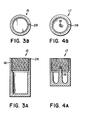
- a filtrate cup 15, shown in Figures 3 and 3A, contains threads 16 at the top portion thereof which are capable of engaging with the complimentary threads 4 located at the bottom portion of the housing 1.
- the filtrate cup 15 can be secured to the housing 1 by screwing the filtrate cup 15 to the housing 1.
- the cup should be vented. Venting can be facilitated if the threads 4, 16 of the filtrate cup and housing do not form an air tight seal.
- the side of the filtrate cup may contain one or more direct vents 28 which intersects with one or more grooves 26, shown in Figure 1, to allow air to pass from the filtrate cup.
- a cap 20 is placeable over the top portion of the housing 1 covering the chamber opening and keys 5 therein.
- a gap 30 between the top of the cap 20 and the top of the housing 1 exists when the cap is placed on the housing. This allows the filter unit to fit within the housing and cap at various different heights. Each height is dictated by the placement of the filter unit stops 11 within the housing keys 5.
- the cap 20 is vented through vent 27 to allow atmospheric pressure to enter into the housing 1 when the device is spun within a centrifuge to prevent the creation of a vacuum therein.
- the apparatus is assembled, as shown in Figure 1, for filtration by inserting the filter unit 6 into the housing 1 so that the neck 7 is inserted within the discharge opening 3 and sealed therein.
- the filtrate cup 15 is then screwed on to the bottom of the housing via the threaded engagement means 4, 16.
- a macro-molecular type solution to be filtered and concentrated may then be placed within the housing 1 in the chamber 2 where it contacts the membrane 12 of the filter unit 6 as well as the inner walls of the housing 1.
- the vented cap 20 is then placed at the top of the housing.
- the entire apparatus may be placed within a centrifuge rotor with the filtrate cup 15 directed outward such that the centrifugal force will direct the filtrate through the membrane 12 and into the filtrate cup 15.
- Filtration will cease when the amount of concentrate within the housing 1 reaches a level below the passageway 9 within the filter unit 6. This level can be adjusted by placing the stops 11 at the upper end of the filter unit within the different keys 5 at the top of the housing so that the height of the passageway 9 may be adjusted.
- the apparatus may be removed from the centrifuge and the filtrate cup 15 unscrewed from the bottom of the housing 1.
- the filtrate will have collected within the filtrate cup 15. Since the apparatus has filtered to dead stop, concentrate will remain within the housing 1. However, the concentrate will not leak from the housing after the filtrate cup has been removed.
- a concentrate cup 17, shown in Figures 4 and 4A, may then be screwed onto the bottom of the housing, and the apparatus placed in a centrifuge and rotated so that the concentrate will collect in the concentrate cup.
- the concentrate cup 17 has a protruding member 18 therein which extends from the bottom of the cup towards the top thereof.
- the protruding member 18 is positioned in the center of the cup such that when the concentrate cup 17 is screwed onto the bottom of the housing, the protruding member 18 contacts the neck 7 of the filter unit 6 and pushes the entire filter member 6 upwards relative to the housing 1.
- the seal between the neck 7, at the bottom portion of the filter unit 6, and discharge opening 3 of the housing 1 formed by the O-rings 10 will no longer be intact. This unseals the bottom portion of the housing 1 and allows the concentrate remaining within the housing to flow through the discharge opening and into the concentrate cup 17.
- the longitudinal passage 8 of filter unit 6 will be sealed by protruding member 18 thereby preventing filtrate from flowing through the discharge opening.
- the apparatus may then be spun in a centrifuge to force the concentrate to flow within the concentrate cup.
- the concentrate remaining within the bottom portion of the housing 1 can be removed with a pipette.
- the apparatus works on the principle that the centrifugal force acts parallel to the plane of the filter membrane 12 unlike the conventional filtration devices where the force acts normal to the plane of a filter membrane located at the bottom of the housing.
- the force exerts a pressure throughout the solution within the housing 1 which is in turn exerted on to the membrane 12.
- This pressure causes filtration through the membrane 12 and into the filter unit 6 where the centrifugal force draws the filtrate towards the discharge opening and into the filtrate cup 15. Since the centrifugal force acts parallel to the membrane plane, the heaviest molecules within the solution and concentration are drawn away from the membrane towards the bottom of the housing where they will not clog the membrane filter 12.
- the force also draws any concentrate which may remain on the membrane surface 12 away from the surface towards the bottom of the filter unit thereby keeping the filter membrane 12 clean.
- the user may obtain higher concentration values by filling the unit with solution to be concentrated, performing the filtration in the centrifuge and then repeating the above procedure one or more times without removing the concentrate between filtrations.
- the filter Since the filter is reusable, the user may perform a filtration, remove the concentrate and then repeat this procedure one or more times. This allows the user to concentrate larger volumes than the maximum volume unit can concentrate in one step.
- the apparatus may be used with a vacuum means in lieu of a centrifuge rotor.
- the filtrate cup 15 contains a side arm 19 having a passage extending through the wall of the filtrate cup.
- a vacuum hose (not shown) may be connected to the side arm 19 to create suction within the filtrate cup.
- the filtrate cup 15 must be completely sealed to the housing 1. This may be accomplished by placing an O-ring seal 25 between the housing 1 and the upper part of the concentrate cup 15. However, other sealing means may be used.
- the apparatus is assembled by placing the filter unit 6 within the housing and the vented cap 20 at the top portion of the housing 1 while the filtrate cup 15 is affixed to the bottom portion of the housing. With a solution in the housing, the suction means can be activated to create a force which draws the filtrate through the bottom portion of the housing 1 into the filtrate cup 15.
- This embodiment contains the same dead stop feature as described in the first embodiment. After filtration has ceased, the concentrate may be removed with a pipette.
Abstract
Description
- This invention relates to the filtration field, and more particularly, to an improved filtration apparatus for filtering and concentrating a solution.
- It is well known that the filtration of fluids may be accomplished through the use of filtration devices which utilize microporous filters to filter and concentrate a macro-molecular solution. This technique has been utilized in centrifugal filtration apparatuses which rely on centrifugal forces to direct solutions towards a filter which separates liquid solutions into filtrate and concentrate.
- There are certain drawbacks, however, associated with the conventional centrifugal filtration apparatus. Typically, such an apparatus contains a filter unit covering the bottom portion of a housing so that the centrifugal force draws the liquid solution towards the filter unit. One disadvantage with this type of system is that the filtration surface area is relatively small when compared to the volume of liquid solution within the housing. Therefore, filtration occurs at a relatively slow rate. Secondly, the filtration devices contain a semi-permeable membrane filter which is conducive to clogging because the heaviest and more dense molecules within the liquid solution are forced into the membrane filter.
- Another problem with the conventional filtration devices is their propensity to filter a solution to dryness so that all of the solution will have been filtered. The apparatus continues to run despite all of the concentrate being filtered. Generally, filtration to dryness should be avoided because the recovery and biological feasibility of concentrate is significantly reduced.
- Certain types of filtration devices, such as that disclosed in U.S. Patent No. 4,632,761 to Bowers et al., are capable of preventing filtration to dryness and contain a dead stop feature which causes filtration to cease while there is concentrate remaining within the apparatus. This device, however, filters to dryness when spun at a 90° angle and therefore the dead stop feature will not work if the device is spun in a swinging bucket centrifuge. Also, in this type of filtration device, the amount of the concentrate remaining after dead stop is dependent upon the angle of rotation of the apparatus. The only means of varying the amount of concentrate remaining in the apparatus is to vary the angle at which the apparatus is rotated. This is impossible to do with fixed angle centrifuge rotors. Accordingly, this device is limited because it will filter to dryness when spun in a swinging bucket centrifuge and cease filtration at only one concentration level when spun in a fixed angle centrifuge.
- It is therefore an object of the present invention to provide a filtration device which may be used in a swinging bucket centrifuge, as well as a fixed angle centrifuge, without filtering to dryness.
- It is also an object of the present invention to provide a filtration device having a relatively high filtration membrane surface area thereby enabling filtration to occur at a higher rate.
- It is also an object of the present invention to provide a filtration device which minimizes the clogging of the semi-permeable membrane thereby maximizing filter efficiency.
- It is also an object of the present invention to provide a filtration apparatus which is self cleaning, and therefore, reusable.
- It is a further object of the present invention to provide a filtration device which contains a variable dead stop feature so that the concentration remaining after filtration can be varied.
- The foregoing problems of the prior art are solved, and the objects of the present invention are achieved, by use of a filtration apparatus constructed in accordance with the principles of the present invention.
- In accordance with the present invention, the filtration apparatus for filtering and concentrating a solution includes a housing having a discharge opening therein; a multiple sided filter unit insertable within the housing; and a means for collecting the filtrate. The filter unit comprises a semi-permeable membrane on one or more sides of the filter unit for separating filtrate from concentrate and allowing filtrate to pass therethrough from within the housing, means for directing filtrate to the discharge opening of the housing, and means for preventing concentrate within the housing from escaping through the discharge opening.
- The means for directing filtrate within the filter unit to the discharge opening of the housing may comprise ridges and the means for preventing concentrate within the housing from escaping through the discharge opening may comprise a seal. The filter unit may also contain a neck having a passage therethrough, the neck being insertable into the discharge opening of the housing for allowing filtrate to flow from the filter unit to the passage and into the discharge opening. The means for collecting the filtrate may include a filtrate cup. The housing may further comprise a threaded engagement means for supporting the filtrate cup having a corresponding threaded engagement means. The filter unit may contain a stop thereon and the housing may contain multiple keys located at different heights from the top portion of the housing. The stop may be inserted into different keys for adjusting the relative position of the filter unit within the housing thereby providing an adjustable dead stop feature.
- These and other objects, features and advantages of the invention will be evident from the following detailed description when read in conjunction with the accompanying drawings in which:
- Figure 1 is a partially cut away side cross sectional view which illustrates a fully assembled filtration apparatus, constructed in accordance with the principles of the present invention, usable within a centrifuge;
- Figures 2 and 2A depict a cross sectional side view and a top view, respectively, of the housing, in accordance with the embodiment shown in Figure 1;
- Figures 3 and 3A depict a cross sectional side view and a top view of a filtrate cup, respectively, in accordance with the embodiment depicted in Figure 1;
- Figures 4 and 4A depict a cross sectional side view and a top view of a concentrate cup, respectively, in accordance with the embodiment depicted in Figure 1;
- Figures 5 and 5A depict a partially cut away front view and a cross sectional view along lines A-A of Figure 5, respectively, of a filter unit usable within the embodiment of the present invention depicted in Figure 1;
- Figure 6 depicts an exploded view of the neck of the filter unit; and
- Figure 7 depicts a side view of a fully assembled apparatus in accordance with the second embodiment of the present invention usable with a vacuum suction device.
- The improved filtration apparatus of the present invention may be embodied in a
centrifugal filtration device 100 such as that shown in Figure 1.Filtration device 100 includes the following major components: housing 1,multi-sided filter unit 6,filtrate cup 15 andcap 20. The structure and function of the components will now be described in detail. - As shown most clearly in Figure 2 and 2A, the filtration device includes a cylindrical housing 1 having a
chamber 2 therein. At the lower portion of the housing, thechamber 2 tapers towards adischarge opening 3 located at the bottom of the housing. The discharge opening 3 is surrounded by a threadedmember 4. At the top of the housing, a plurality ofkeys 5 are located. Thekeys 5 are spaced at different positions along the top perimeter of the housing 1 as shown in Figure 2A. - A two-
sided filter unit 6, as shown in Figures 5 and 5A, is insertable withinchamber 2 of the housing 1. Thefilter unit 6 is flat shaped with both surfaces exposed. The lower portion of the filter unit is tapered to correspond with the tapered shape of the lower portion of the housing 1. The tapered portion of thefilter unit 6 extends into aneck 7 which is cylindrical in shape. As shown in Figure 6, the neck contains alongitudinal passage 8 running therethrough from the end of the neck to a point on the filter unit, at the lower tapered edge, intersecting atransverse passageway 9 extending between the opposite flat surfaces ofunit 6. A sealing means, such as one or more rubber O-rings 10, is located around theneck 7 of thefilter unit 6. The sealing means may also be molded intoneck 7 offilter unit 6. The molded in sealing means may take the form of molded in "O" rings onneck 7 offilter unit 6 or may simply be an interference fit betweenneck 7 offilter unit 6 and discharge opening 3 of housing 1. - As shown in Figure 1, the
filter unit 6 is insertable within the housing 1 so that theneck 7 of thefilter unit 6 fits into the discharge opening 3 at the bottom of the housing. When this occurs, the O-rings 10 on theneck 7 contact the inner wall of the discharge opening of thehousing 3 to provide a liquid tight seal. The upper portion of thefilter unit 6 contains one or more stops 11 located at the edges thereof. When thefilter unit 6 is inserted into the housing 1, the stops 11 may be inserted into any of thekeys 5 located at the upper perimeter of the housing. Thekeys 5 extend at different depths along the top of the housing 1 thereby enabling the filter unit to be placed at different heights within the housing 1. Each height corresponds to a different dead stop time or amount of concentrate left in thechamber 2 after filtration has ceased. Since theneck 7 of thefilter unit 6 is elongate and insertable into thedischarge opening 3 of the housing, variation of the filter unit height will not affect the sealing between thefilter unit 6 and housing 1 by the O-rings 10. Therefore, concentrate will not escape from the housing even if thefilter unit 6 is at different heights. - As shown in Figure 5A, each side of the
filter unit 6 contains asemi-permeable membrane 12 which separates filtrate from concentrated solution within thechamber 2. Each side of thefilter unit 6 containsridges 13 thereon which define grooves 14 (as shown in Figure 5) for directing filtrate, which has passed through the membrane towards theneck 7 of thefilter unit 6, to thedischarge 3 of the housing. The grooves formed by the ridges run along thefilter unit 6 surface towards thepassageway 9 at the bottom tapered portion of the filter unit which leads to thepassage 8 within theneck 7 located at the lower end of the housing 1. Filtrate which penetrates themembrane 12 is drawn towards thepassageway 9 and into thepassage 8 where it flows to thedischarge opening 3 of the housing 1. - As shown in Figure 5, the membrane may be heat sealed, ultrasonically sealed, glued or sealed by any other means to the outer perimeter of each side of the
filter unit 6. Theheat seal 29 effectively prevents concentrate within the housing from flowing into thepassageway 9 and into thedischarge opening 3. - A
filtrate cup 15, shown in Figures 3 and 3A, containsthreads 16 at the top portion thereof which are capable of engaging with thecomplimentary threads 4 located at the bottom portion of the housing 1. Using this means, thefiltrate cup 15 can be secured to the housing 1 by screwing thefiltrate cup 15 to the housing 1. In order to prevent pressure build up within thefiltrate cup 15, the cup should be vented. Venting can be facilitated if thethreads direct vents 28 which intersects with one ormore grooves 26, shown in Figure 1, to allow air to pass from the filtrate cup. - As shown in Figure 1, a
cap 20 is placeable over the top portion of the housing 1 covering the chamber opening andkeys 5 therein. As shown in Figure 1, agap 30 between the top of thecap 20 and the top of the housing 1 exists when the cap is placed on the housing. This allows the filter unit to fit within the housing and cap at various different heights. Each height is dictated by the placement of the filter unit stops 11 within thehousing keys 5. Thecap 20 is vented throughvent 27 to allow atmospheric pressure to enter into the housing 1 when the device is spun within a centrifuge to prevent the creation of a vacuum therein. - The apparatus is assembled, as shown in Figure 1, for filtration by inserting the
filter unit 6 into the housing 1 so that theneck 7 is inserted within thedischarge opening 3 and sealed therein. Thefiltrate cup 15 is then screwed on to the bottom of the housing via the threaded engagement means 4, 16. A macro-molecular type solution to be filtered and concentrated, may then be placed within the housing 1 in thechamber 2 where it contacts themembrane 12 of thefilter unit 6 as well as the inner walls of the housing 1. The ventedcap 20 is then placed at the top of the housing. The entire apparatus may be placed within a centrifuge rotor with thefiltrate cup 15 directed outward such that the centrifugal force will direct the filtrate through themembrane 12 and into thefiltrate cup 15. Filtration will cease when the amount of concentrate within the housing 1 reaches a level below thepassageway 9 within thefilter unit 6. This level can be adjusted by placing the stops 11 at the upper end of the filter unit within thedifferent keys 5 at the top of the housing so that the height of thepassageway 9 may be adjusted. - After filtration has ceased, i.e., dead stop has occurred, the apparatus may be removed from the centrifuge and the
filtrate cup 15 unscrewed from the bottom of the housing 1. The filtrate will have collected within thefiltrate cup 15. Since the apparatus has filtered to dead stop, concentrate will remain within the housing 1. However, the concentrate will not leak from the housing after the filtrate cup has been removed. Aconcentrate cup 17, shown in Figures 4 and 4A, may then be screwed onto the bottom of the housing, and the apparatus placed in a centrifuge and rotated so that the concentrate will collect in the concentrate cup. - The
concentrate cup 17 has a protrudingmember 18 therein which extends from the bottom of the cup towards the top thereof. The protrudingmember 18 is positioned in the center of the cup such that when theconcentrate cup 17 is screwed onto the bottom of the housing, the protrudingmember 18 contacts theneck 7 of thefilter unit 6 and pushes theentire filter member 6 upwards relative to the housing 1. The seal between theneck 7, at the bottom portion of thefilter unit 6, and dischargeopening 3 of the housing 1 formed by the O-rings 10 will no longer be intact. This unseals the bottom portion of the housing 1 and allows the concentrate remaining within the housing to flow through the discharge opening and into theconcentrate cup 17. Thelongitudinal passage 8 offilter unit 6 will be sealed by protrudingmember 18 thereby preventing filtrate from flowing through the discharge opening. The apparatus may then be spun in a centrifuge to force the concentrate to flow within the concentrate cup. Alternatively, to avoid respining the apparatus in a centrifuge, the concentrate remaining within the bottom portion of the housing 1 can be removed with a pipette. - The apparatus works on the principle that the centrifugal force acts parallel to the plane of the
filter membrane 12 unlike the conventional filtration devices where the force acts normal to the plane of a filter membrane located at the bottom of the housing. The force, however, exerts a pressure throughout the solution within the housing 1 which is in turn exerted on to themembrane 12. This pressure causes filtration through themembrane 12 and into thefilter unit 6 where the centrifugal force draws the filtrate towards the discharge opening and into thefiltrate cup 15. Since the centrifugal force acts parallel to the membrane plane, the heaviest molecules within the solution and concentration are drawn away from the membrane towards the bottom of the housing where they will not clog themembrane filter 12. The force also draws any concentrate which may remain on themembrane surface 12 away from the surface towards the bottom of the filter unit thereby keeping thefilter membrane 12 clean. These features enable the filter membrane to operate at optimal efficiency since the heaviest molecules and concentrate on the membrane are drawn to the lower portion of the housing. - The user may obtain higher concentration values by filling the unit with solution to be concentrated, performing the filtration in the centrifuge and then repeating the above procedure one or more times without removing the concentrate between filtrations.
- Since the filter is reusable, the user may perform a filtration, remove the concentrate and then repeat this procedure one or more times. This allows the user to concentrate larger volumes than the maximum volume unit can concentrate in one step.
- In an alternate embodiment of the present invention, shown in Figure 7, the apparatus may be used with a vacuum means in lieu of a centrifuge rotor. In this embodiment, the
filtrate cup 15 contains aside arm 19 having a passage extending through the wall of the filtrate cup. When the filtrate cup is affixed to the bottom portion of the housing by screwing thereon, a vacuum hose (not shown) may be connected to theside arm 19 to create suction within the filtrate cup. In this particular embodiment, thefiltrate cup 15 must be completely sealed to the housing 1. This may be accomplished by placing an O-ring seal 25 between the housing 1 and the upper part of theconcentrate cup 15. However, other sealing means may be used. - The apparatus according to the alternative embodiment, is assembled by placing the
filter unit 6 within the housing and the ventedcap 20 at the top portion of the housing 1 while thefiltrate cup 15 is affixed to the bottom portion of the housing. With a solution in the housing, the suction means can be activated to create a force which draws the filtrate through the bottom portion of the housing 1 into thefiltrate cup 15. This embodiment contains the same dead stop feature as described in the first embodiment. After filtration has ceased, the concentrate may be removed with a pipette. - It will be evident that the invention may be embodied in a variety of manners other than those depicted herein. Any such embodiments are intended to be within the scope of the invention as defined by the claims.
Claims (15)
Applications Claiming Priority (2)
| Application Number | Priority Date | Filing Date | Title |
|---|---|---|---|
| US595533 | 1990-10-11 | ||
| US07/595,533 US5112484A (en) | 1990-10-11 | 1990-10-11 | Filtration apparatus |
Publications (3)
| Publication Number | Publication Date |
|---|---|
| EP0480298A2 true EP0480298A2 (en) | 1992-04-15 |
| EP0480298A3 EP0480298A3 (en) | 1992-07-29 |
| EP0480298B1 EP0480298B1 (en) | 1997-07-02 |
Family
ID=24383615
Family Applications (1)
| Application Number | Title | Priority Date | Filing Date |
|---|---|---|---|
| EP91116825A Expired - Lifetime EP0480298B1 (en) | 1990-10-11 | 1991-10-02 | Filtration apparatus |
Country Status (3)
| Country | Link |
|---|---|
| US (1) | US5112484A (en) |
| EP (1) | EP0480298B1 (en) |
| DE (1) | DE69126691T2 (en) |
Cited By (3)
| Publication number | Priority date | Publication date | Assignee | Title |
|---|---|---|---|---|
| WO2000035565A2 (en) * | 1998-12-04 | 2000-06-22 | Orbital Biosciences, Llc | Ultrafiltration device and method of forming same |
| EP2192968A1 (en) * | 2007-09-24 | 2010-06-09 | Millipore Corporation | Centrifugal filter |
| US9103756B2 (en) | 2011-07-13 | 2015-08-11 | Emd Millipore Corporation | All-in-one sample preparation device and method |
Families Citing this family (39)
| Publication number | Priority date | Publication date | Assignee | Title |
|---|---|---|---|---|
| US5585007A (en) * | 1994-12-07 | 1996-12-17 | Plasmaseal Corporation | Plasma concentrate and tissue sealant methods and apparatuses for making concentrated plasma and/or tissue sealant |
| US5490927A (en) * | 1995-01-04 | 1996-02-13 | Filtron Technology Corporation | Filtration apparatus with membrane filter unit |
| US5733449A (en) * | 1995-12-08 | 1998-03-31 | Orbital Biosciences, Llc | Microconcentrator device |
| US6156199A (en) * | 1997-08-11 | 2000-12-05 | Zuk, Jr.; Peter | Centrifugal filtration apparatus |
| US20030205538A1 (en) | 2002-05-03 | 2003-11-06 | Randel Dorian | Methods and apparatus for isolating platelets from blood |
| US7832566B2 (en) | 2002-05-24 | 2010-11-16 | Biomet Biologics, Llc | Method and apparatus for separating and concentrating a component from a multi-component material including macroparticles |
| US7992725B2 (en) | 2002-05-03 | 2011-08-09 | Biomet Biologics, Llc | Buoy suspension fractionation system |
| AU2003249642A1 (en) | 2002-05-24 | 2003-12-12 | Biomet Manufacturing Corp. | Apparatus and method for separating and concentrating fluids containing multiple components |
| US20060278588A1 (en) | 2002-05-24 | 2006-12-14 | Woodell-May Jennifer E | Apparatus and method for separating and concentrating fluids containing multiple components |
| US7845499B2 (en) | 2002-05-24 | 2010-12-07 | Biomet Biologics, Llc | Apparatus and method for separating and concentrating fluids containing multiple components |
| US7866485B2 (en) | 2005-02-07 | 2011-01-11 | Hanuman, Llc | Apparatus and method for preparing platelet rich plasma and concentrates thereof |
| EP2666494B1 (en) | 2005-02-07 | 2018-01-17 | Hanuman LLC | Platelet rich plasma concentrate apparatus and method |
| US7708152B2 (en) * | 2005-02-07 | 2010-05-04 | Hanuman Llc | Method and apparatus for preparing platelet rich plasma and concentrates thereof |
| CN101312785B (en) * | 2005-09-02 | 2011-03-30 | 罗什生命科学公司 | Systems, apparatus and methods for vacuum filtration |
| US8567609B2 (en) | 2006-05-25 | 2013-10-29 | Biomet Biologics, Llc | Apparatus and method for separating and concentrating fluids containing multiple components |
| US8430813B2 (en) * | 2006-05-26 | 2013-04-30 | Depuy Spine, Inc. | Illuminated surgical access system including a surgical access device and integrated light emitter |
| EP2146794B1 (en) | 2007-04-12 | 2016-10-19 | Biomet Biologics, LLC | Buoy suspension fractionation system |
| US8328024B2 (en) | 2007-04-12 | 2012-12-11 | Hanuman, Llc | Buoy suspension fractionation system |
| US8158009B2 (en) * | 2007-05-23 | 2012-04-17 | Roush Life Sciences, Llc | Methods and apparatus for foam control in a vacuum filtration system |
| EP2183040B1 (en) * | 2007-07-26 | 2012-03-07 | Roush Life Sciences, LLC | Methods and apparatus for supporting a vacuum filtration device |
| US8231012B2 (en) * | 2007-07-26 | 2012-07-31 | Roush Life Sciences, Llc | Filtrate storage system |
| EP2567692B1 (en) | 2008-02-27 | 2016-04-06 | Biomet Biologics, LLC | Use of a device for obtaining interleukin-1 receptor antagonist rich solutions |
| EP2254991B1 (en) | 2008-02-29 | 2018-08-22 | Biomet Manufacturing, LLC | A system and process for separating a material |
| US8012077B2 (en) | 2008-05-23 | 2011-09-06 | Biomet Biologics, Llc | Blood separating device |
| US8187475B2 (en) | 2009-03-06 | 2012-05-29 | Biomet Biologics, Llc | Method and apparatus for producing autologous thrombin |
| US8313954B2 (en) | 2009-04-03 | 2012-11-20 | Biomet Biologics, Llc | All-in-one means of separating blood components |
| US9011800B2 (en) | 2009-07-16 | 2015-04-21 | Biomet Biologics, Llc | Method and apparatus for separating biological materials |
| US20110214615A1 (en) * | 2010-03-05 | 2011-09-08 | Martin Shan | Animal confinement housing configured for improved forced air ventilation |
| US8591391B2 (en) | 2010-04-12 | 2013-11-26 | Biomet Biologics, Llc | Method and apparatus for separating a material |
| US9642956B2 (en) | 2012-08-27 | 2017-05-09 | Biomet Biologics, Llc | Apparatus and method for separating and concentrating fluids containing multiple components |
| US10143725B2 (en) | 2013-03-15 | 2018-12-04 | Biomet Biologics, Llc | Treatment of pain using protein solutions |
| US20140271589A1 (en) | 2013-03-15 | 2014-09-18 | Biomet Biologics, Llc | Treatment of collagen defects using protein solutions |
| US9950035B2 (en) | 2013-03-15 | 2018-04-24 | Biomet Biologics, Llc | Methods and non-immunogenic compositions for treating inflammatory disorders |
| US9895418B2 (en) | 2013-03-15 | 2018-02-20 | Biomet Biologics, Llc | Treatment of peripheral vascular disease using protein solutions |
| US10208095B2 (en) | 2013-03-15 | 2019-02-19 | Biomet Manufacturing, Llc | Methods for making cytokine compositions from tissues using non-centrifugal methods |
| EP3213821A4 (en) * | 2014-10-27 | 2018-05-02 | Liu, Yuemeng | Centrifuge filter tube |
| US9713810B2 (en) | 2015-03-30 | 2017-07-25 | Biomet Biologics, Llc | Cell washing plunger using centrifugal force |
| US9757721B2 (en) | 2015-05-11 | 2017-09-12 | Biomet Biologics, Llc | Cell washing plunger using centrifugal force |
| CN105061552A (en) * | 2015-09-02 | 2015-11-18 | 常州市长宇实用气体有限公司 | Device for improving protein crystallization rate |
Citations (4)
| Publication number | Priority date | Publication date | Assignee | Title |
|---|---|---|---|---|
| US4123224A (en) * | 1975-12-17 | 1978-10-31 | American Home Products Corporation | Diagnostic test device |
| FR2553005A1 (en) * | 1983-10-06 | 1985-04-12 | Terumo Corp | FILTRATION DEVICE FOR LIQUIDS |
| EP0184852A2 (en) * | 1984-12-14 | 1986-06-18 | Becton Dickinson and Company | Automatic liquid component separator |
| EP0315252A1 (en) * | 1987-11-06 | 1989-05-10 | Akzo Nobel N.V. | Separator for cell-containing liquids |
Family Cites Families (6)
| Publication number | Priority date | Publication date | Assignee | Title |
|---|---|---|---|---|
| US3469369A (en) * | 1966-12-29 | 1969-09-30 | Bell Telephone Labor Inc | Method for preparing and applying a viscous fluid |
| US3441143A (en) * | 1967-02-10 | 1969-04-29 | Marvel Eng Co | Plural element filter assembly |
| GB2104401B (en) * | 1981-08-25 | 1985-03-20 | Krauss Maffei Ag | Support plate for centrifuges |
| US4632761A (en) * | 1983-08-15 | 1986-12-30 | W. R. Grace & Co. | Centrifugal microconcentrator and methods for its use |
| US4755300A (en) * | 1985-12-23 | 1988-07-05 | Haemonetics Corporation | Couette membrane filtration apparatus for separating suspended components in a fluid medium using high shear |
| US4832851A (en) * | 1987-02-02 | 1989-05-23 | W. R. Grace & Co. | Centrifugal force-enhanced filtration of fluids |
-
1990
- 1990-10-11 US US07/595,533 patent/US5112484A/en not_active Expired - Lifetime
-
1991
- 1991-10-02 DE DE69126691T patent/DE69126691T2/en not_active Expired - Lifetime
- 1991-10-02 EP EP91116825A patent/EP0480298B1/en not_active Expired - Lifetime
Patent Citations (4)
| Publication number | Priority date | Publication date | Assignee | Title |
|---|---|---|---|---|
| US4123224A (en) * | 1975-12-17 | 1978-10-31 | American Home Products Corporation | Diagnostic test device |
| FR2553005A1 (en) * | 1983-10-06 | 1985-04-12 | Terumo Corp | FILTRATION DEVICE FOR LIQUIDS |
| EP0184852A2 (en) * | 1984-12-14 | 1986-06-18 | Becton Dickinson and Company | Automatic liquid component separator |
| EP0315252A1 (en) * | 1987-11-06 | 1989-05-10 | Akzo Nobel N.V. | Separator for cell-containing liquids |
Cited By (12)
| Publication number | Priority date | Publication date | Assignee | Title |
|---|---|---|---|---|
| WO2000035565A2 (en) * | 1998-12-04 | 2000-06-22 | Orbital Biosciences, Llc | Ultrafiltration device and method of forming same |
| WO2000035565A3 (en) * | 1998-12-04 | 2000-11-23 | Orbital Biosciences Llc | Ultrafiltration device and method of forming same |
| EP2192968A1 (en) * | 2007-09-24 | 2010-06-09 | Millipore Corporation | Centrifugal filter |
| EP2192968A4 (en) * | 2007-09-24 | 2011-08-31 | Millipore Corp | Centrifugal filter |
| EP2457631A1 (en) * | 2007-09-24 | 2012-05-30 | Millipore Corporation | Centrifugal filter |
| US8357296B2 (en) | 2007-09-24 | 2013-01-22 | Emd Millipore Corporation | Centrifugal filter |
| US8747670B2 (en) | 2007-09-24 | 2014-06-10 | Emd Millipore Corporation | Centrifugal filter |
| US9050565B2 (en) | 2007-09-24 | 2015-06-09 | Emd Millipore Corporation | Centrifugal filter |
| US9295947B2 (en) | 2007-09-24 | 2016-03-29 | Emd Millipore Corporation | Centrifugal filter |
| US9103756B2 (en) | 2011-07-13 | 2015-08-11 | Emd Millipore Corporation | All-in-one sample preparation device and method |
| US9304070B2 (en) | 2011-07-13 | 2016-04-05 | Emd Millipore Corporation | All-in-one sample preparation device and method |
| US9897520B2 (en) | 2011-07-13 | 2018-02-20 | Emd Millipore Corporation | All-in-one sample preparation device and method |
Also Published As
| Publication number | Publication date |
|---|---|
| DE69126691T2 (en) | 1998-02-05 |
| DE69126691D1 (en) | 1997-08-07 |
| EP0480298B1 (en) | 1997-07-02 |
| US5112484A (en) | 1992-05-12 |
| EP0480298A3 (en) | 1992-07-29 |
Similar Documents
| Publication | Publication Date | Title |
|---|---|---|
| US5112484A (en) | Filtration apparatus | |
| WO2001085299A1 (en) | Centrifugal filtration apparatus | |
| EP0237674A2 (en) | Filter for centrifuge tube | |
| EP0651675B1 (en) | Centrifugal method for concentrating macromolecules from a solution and device for carrying out said method | |
| US7819954B2 (en) | Gas/liquid separator including a liquid trap filter | |
| US5879624A (en) | Method and apparatus for collecting and processing blood | |
| US4871462A (en) | Enhanced separation of blood components | |
| EP1919622B1 (en) | Systems, apparatus and methods for vacuum filtration | |
| EP1140246B1 (en) | Reservoir-and-filter system | |
| EP1031371A1 (en) | Filtering unit having separately attachable filter cassette and method of filtering | |
| EP0040427A1 (en) | Suction liquid collection assembly and flexible liquid collection bag suitable for use therein | |
| EP0358302A2 (en) | Medico-surgical suction container | |
| AU6182298A (en) | In-line gravity driven liquid filtration device useable to filter blood or blood products | |
| GB2133306A (en) | Filtration apparatus | |
| EP0858347A2 (en) | Container with integral pump platen | |
| US6344140B1 (en) | Centrifugal filtration apparatus | |
| US6660171B2 (en) | High capacity gravity feed filter for filtering blood and blood products | |
| US5490927A (en) | Filtration apparatus with membrane filter unit | |
| US6419842B1 (en) | Method and installation for separating solids contents from a pulp | |
| JPH03209146A (en) | Throw-away concentrator for use in multiple concentration | |
| JP2000180443A (en) | Recovery method of haemofiltration residue | |
| GB2331746A (en) | Filtration device | |
| CN111282339B (en) | Suction filtration type water-sand separation device for annular water tank | |
| KR102444547B1 (en) | Non-powered rotation filtering apparatus | |
| JP3264013B2 (en) | Membrane separation device |
Legal Events
| Date | Code | Title | Description |
|---|---|---|---|
| PUAI | Public reference made under article 153(3) epc to a published international application that has entered the european phase |
Free format text: ORIGINAL CODE: 0009012 |
|
| 17P | Request for examination filed |
Effective date: 19911220 |
|
| AK | Designated contracting states |
Kind code of ref document: A2 Designated state(s): DE FR GB |
|
| PUAL | Search report despatched |
Free format text: ORIGINAL CODE: 0009013 |
|
| AK | Designated contracting states |
Kind code of ref document: A3 Designated state(s): DE FR GB |
|
| 17Q | First examination report despatched |
Effective date: 19940203 |
|
| GRAG | Despatch of communication of intention to grant |
Free format text: ORIGINAL CODE: EPIDOS AGRA |
|
| GRAH | Despatch of communication of intention to grant a patent |
Free format text: ORIGINAL CODE: EPIDOS IGRA |
|
| GRAH | Despatch of communication of intention to grant a patent |
Free format text: ORIGINAL CODE: EPIDOS IGRA |
|
| GRAA | (expected) grant |
Free format text: ORIGINAL CODE: 0009210 |
|
| AK | Designated contracting states |
Kind code of ref document: B1 Designated state(s): DE FR GB |
|
| REF | Corresponds to: |
Ref document number: 69126691 Country of ref document: DE Date of ref document: 19970807 |
|
| ET | Fr: translation filed | ||
| PLBE | No opposition filed within time limit |
Free format text: ORIGINAL CODE: 0009261 |
|
| STAA | Information on the status of an ep patent application or granted ep patent |
Free format text: STATUS: NO OPPOSITION FILED WITHIN TIME LIMIT |
|
| 26N | No opposition filed | ||
| REG | Reference to a national code |
Ref country code: GB Ref legal event code: IF02 |
|
| PGFP | Annual fee paid to national office [announced via postgrant information from national office to epo] |
Ref country code: GB Payment date: 20100929 Year of fee payment: 20 |
|
| PGFP | Annual fee paid to national office [announced via postgrant information from national office to epo] |
Ref country code: FR Payment date: 20101020 Year of fee payment: 20 |
|
| PGFP | Annual fee paid to national office [announced via postgrant information from national office to epo] |
Ref country code: DE Payment date: 20100929 Year of fee payment: 20 |
|
| REG | Reference to a national code |
Ref country code: DE Ref legal event code: R071 Ref document number: 69126691 Country of ref document: DE |
|
| REG | Reference to a national code |
Ref country code: DE Ref legal event code: R071 Ref document number: 69126691 Country of ref document: DE |
|
| REG | Reference to a national code |
Ref country code: GB Ref legal event code: PE20 Expiry date: 20111001 |
|
| PG25 | Lapsed in a contracting state [announced via postgrant information from national office to epo] |
Ref country code: GB Free format text: LAPSE BECAUSE OF EXPIRATION OF PROTECTION Effective date: 20111001 |
|
| PG25 | Lapsed in a contracting state [announced via postgrant information from national office to epo] |
Ref country code: DE Free format text: LAPSE BECAUSE OF EXPIRATION OF PROTECTION Effective date: 20111003 |