EP0483957B1 - Improving images in video displays - Google Patents
Improving images in video displays Download PDFInfo
- Publication number
- EP0483957B1 EP0483957B1 EP91307898A EP91307898A EP0483957B1 EP 0483957 B1 EP0483957 B1 EP 0483957B1 EP 91307898 A EP91307898 A EP 91307898A EP 91307898 A EP91307898 A EP 91307898A EP 0483957 B1 EP0483957 B1 EP 0483957B1
- Authority
- EP
- European Patent Office
- Prior art keywords
- image
- pixel
- field
- video
- intrafield
- Prior art date
- Legal status (The legal status is an assumption and is not a legal conclusion. Google has not performed a legal analysis and makes no representation as to the accuracy of the status listed.)
- Expired - Lifetime
Links
Images


Classifications
-
- H—ELECTRICITY
- H04—ELECTRIC COMMUNICATION TECHNIQUE
- H04N—PICTORIAL COMMUNICATION, e.g. TELEVISION
- H04N7/00—Television systems
- H04N7/01—Conversion of standards, e.g. involving analogue television standards or digital television standards processed at pixel level
- H04N7/0127—Conversion of standards, e.g. involving analogue television standards or digital television standards processed at pixel level by changing the field or frame frequency of the incoming video signal, e.g. frame rate converter
- H04N7/0132—Conversion of standards, e.g. involving analogue television standards or digital television standards processed at pixel level by changing the field or frame frequency of the incoming video signal, e.g. frame rate converter the field or frame frequency of the incoming video signal being multiplied by a positive integer, e.g. for flicker reduction
-
- H—ELECTRICITY
- H04—ELECTRIC COMMUNICATION TECHNIQUE
- H04N—PICTORIAL COMMUNICATION, e.g. TELEVISION
- H04N5/00—Details of television systems
- H04N5/14—Picture signal circuitry for video frequency region
- H04N5/144—Movement detection
- H04N5/145—Movement estimation
Definitions
- This invention relates generally to image display systems and more particularly to computer controlled systems for enhancing digitised video images.
- interlace video which is conventional in video technology, a single image or frame is actually composed of two images taken typically 1/60 second apart. The first image contains even numbered scan lines and the second image odd numbered scan lines interlaced between the even scan lines after display of the first image.
- An example of this interlaced form of scanning may be found in conventional broadcast television raster scan images.
- a method is known of operating a video display in which images are presented sequentially in a plurality of interlaced fields, each field consisting of an array of pixels together representing an image, including the steps of: detecting interfield differences between said plurality of fields by generating a measurement of high frequency interfield detail between said plurality of fields derived from a plurality of vertically aligned adjacent pixels within ones of said fields; generating a measurement of intrafield detail as a function of a plurality of vertically aligned adjacent pixels in said fields; comparing said interfield differences with intrafield differences to identify pixels corresponding to motion within the image; and replacing the pixel values of said identified pixels with values functionally related to the pixel values in the same area of said image from another of said fields. See US-A-4845557.
- This invention provides a method of operating a video display in which images are presented sequentially in at least first and second interlaced fields, each field consisting of an array of pixels together representing an image, including the steps of: generating a measurement (H) of high frequency interfield detail between said first and said second fields by subtracting weighted pixel values of all pixels in said first interlaced field from weighted pixel values of all pixels in said second interlaced field within a designated area comprising a predetermined number of rows and a predetermined number of columns around a pixel of interest within the image, said predetermined number of columns being at least two; generating a measurement (T) of intrafield detail on the basis of intrafield differences between the pixel values of the odd and even rows of said first interlaced field within said designated area and on the basis of intrafield differences between the odd and even rows of said second interlaced field within said designated area; determining whether said interfield measurement divided by said intrafield measurement lies within a predetermined range and, if so, replacing the pixel value of the pixel of interest
- digitised video images of captured analog video data are derived from an original interlaced image.
- First a still image from an interlaced video source is captured or digitised employing any of a number of commercially available video digitising systems.
- This capturing includes in a preferred embodiment a first and second sequential field which comprise a full frame. These fields are then processed digitally so as to determine areas corrupted by relative motion of the target. In these areas of pels wherein such motion is detected, substitution of pel values in one field is made based upon estimates derived from pels in the remaining field.
- interfield differences extending vertically and coherently over several pels which are also larger than intrafield detail in that area are scanned for by a digital processor.
- the first or even field will contain pels unaltered from their original capture state.
- an operator modifies each of the pels in this odd field in accordance with the invention.
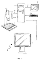
- Figs 1 and 2 show a representative system for capture, digitising, processing and display of a video image
- Fig 3 depicts a schematic representation of a portion of pels comprising a captured image
- Fig 4 is a flow diagram showing the processing of pels in accordance with the invention.
- system 10 may preferably take the form of a digital personal computer and includes a keyboard 6 for providing user input which is coupled to a central processing unit or host PC 4 in a manner well known in the art.
- host 4 includes memory devices, which may comprise both volatile and non-volatile memory storage devices and which may include auxiliary memory devices such as magnetic disk or tape storage.
- Host 4 is also coupled to one or more display drivers (not shown) which are utilised, in a manner well known in the art, to provide a visual display of video images by coupling appropriate control and data signals from the host 4 to the display 5 and one or more monitors 7.
- display 5 and monitor 7 may be comprised of a variety of devices such as those adapted to receive analog video in varying formats such as RGB, Y/C, NTSC, PAL and the like.
- a video camera 3 is further included having an analog video link 32 to the host 4.
- the camera 3 is shown to be trained on an object 2 having visual images to be digitised by the system 10.
- the object 2 is shown as stationary, it will be appreciated that to gain a maximum benefit of the subject invention as disclosed herein, this object may more preferably take the form of a moving subject such as a human, vehicle, or the like. The image of which when captured gives rise to the blurring effect addressed by the invention.
- the camera 3 will transfer the visual image of object 2 into analog electronic signals carried on the link 32 to the host 4 wherein they will subsequently be digitised, processed and reconverted into analog form for output on analog output link 34 after which they are displayed on one or more monitors 7.
- the system 10 may, of course, include other components and as to the general digital computer and display portions, the system may preferably be implemented by means of an IBM Model No. 80 PS/2 computer manufactured by International Business Machines Corporation of Armonk, New York.
- the host 4 includes a bus system facilitating data, control, and address I/O to various components of the system in a manner well known in the art.
- a bus system facilitating data, control, and address I/O to various components of the system in a manner well known in the art.
- a proprietary Micro Channel (Micro Channel is a trademark of the International Business Machines Corporation) bus system is employed which is desired in a preferred embodiment of the system 10.
- the invention is not intended to be so limited to a particular bus structure and contemplates use with other bus structures. More detailed information regarding this microchannel bus structure and operation may be obtained with reference to the technical manuals accompanying the Model 80 machine which is incorporated herein by reference.
- analog video input signals on link 32 have been shown as originating from the camera 3, it will be readily appreciated that such analog video source material may be generated from a number of other sources such as the familiar VCR or VTR (video tape recorder), or the like and accordingly the invention is not intended to be limited to use with any particular source for generating such analog signals.
- these sources of analog video signals may be in a number of formats such as the aforementioned RGB, Y/C, composite video, digital, or other formats. Although only one source of such formatted video information is shown in Fig.
- FIG. 1 A computer monitor 5 has been shown in Fig. 1 which conventionally comprises a portion of a general personal computer system including the host 4 and is used for conventional purposes of I/O with the host 4.
- a monitor 7 has further been included for display of these re-converted analog video signals.
- adapter card or expansion slots are provided in the various available hosts 4 .
- the purpose of these slots is to enable a user to custom configure a system to perform desired functions.
- An adapter card in one of the slots will carry connectors for receiving raw analog video source data in multiple formats and multiplexing/control hardware and the like on the card which, under computer control by interfacing with the aforementioned bus, will select one of these signals for digitisation.
- This adapter card will further include the analog-to-digital circuitry necessary to digitise this preselected signal.
- a feature of the invention is to provide for processing and editing of this thereby digitised image under control of the host 4 computer through the bus to eliminate motion artifacts in a manner to be described.
- a further function of the adapter card is to then re-convert the processed/edited digitised video information into analog form, such function also being performed on board on the card by provision of appropriate digital-to-analog conversion circuitry.
- encoder circuitry is provided on the adapter card whereby when the digitised video signals are re-converted to analog form they are converted in multiple formats.
- Multiple connectors are provided on the card each carrying a different one of these re-converted digitised signals in a different one of the conventional analog video formats. In this manner, by connecting a monitor to each such connector adapted to receive that connector's particular signal format, simultaneous display of the video image in multiple formats results. It will be noted that this re-conversion is also under computer 4 in as much as the adapter card and associated encoder circuitry is plugged into the interface bus of the computer 4.
- FIG. 2 a more detailed functional block diagram of the system 10 of Fig. 1 is illustrated which will now be described.
- analog video input signals in a variety of formats are received by the video adapter 16 of the invention.
- the video adapter 16 is connected to the host system 12 by the video device driver 18 which receives status from the adapter on lines 36 and sends commands and data to registers of adapter 16 on line 38.
- the bus of the system 10 is illustrated graphically in part by output on line 26 going from adapter 16 into the video buffers 28 inside the host processor 12. Further function of this bus is illustrated by line 30 indicating information stored in this video buffer 28 may be loaded into host storage such as a PC hard disk 22. From storage 22 via the bus, again illustrated by a line, 24, data can be received from the disk and put back into the buffer 28 of host 12. From these buffers 28 data may also be read and then sent back via the host bus connection to the adapter 16 on line 32 to load video data into the video memory of the adapter 16.
- a video device driver 18 has a video application programming interface 20 which directly interfaces as shown by line 15 with the video capture and edit capability or function 14 of the host system 10.
- the application programming interface 20 provides microcommands for the video capture and edit process that are ultimately delivered to the video adapter 16 via the device driver box 18.
- commands are sent via lines 40 to and status information is received via lines 42 from the system processor of host 12. This results in an image being displayed on the screen of one or more monitors 7, Fig. 1.
- the screen 17 of host 12 will generally be reserved for display of non-source material, i.e., the more conventional I/O data associated with personal computer systems. Such data includes operator input from keyboard 6, and user-interface information from the host 12 for operating the capture and display features of the invention.
- the displayed image may be live or a composite image including images controlled by the function selected by the video capture and edit function 14 and the application programming interface 20 is via microcommands which are then in turn converted into individual separate commands and status requests across lines 36 and 38.
- functions indicated by lines 32, 30, 24 and 26 are all actually handled via the bus itself of system 10 and generally represent disk 22 I/O and adapter card 16 I/O.
- the system and method of the invention retains most of the resolution of a full interlaced image while eliminating the image shake of fast moving components. In a preferred embodiment this is accomplished in two steps. The first step identifies those areas of the image which are shaking or jittering, e.g. exhibiting undesirable noise motion, and the second step discards the second field in only those identified areas, substituting an estimate for pels in those areas based upon the other field. The resolution loss is thus confined to small areas that, because of rapid motion, were not sharply defined anyway.
- Fig. 3 depicts a schematic representation of a portion of pels comprising a captured image. It will be recalled that these pels will be comprised of two groups, first odd field pels 50 and a second collection of even field pels 54 interspersed or interlaced between the odd field pels. For illustrative purposes, particular ones of these pels have been accorded a notation such as pel 56 (C 2 ), the purpose of which will be hereinafter made clear and refers to a gray scale value of the particular pel.
- pel 56 C 2
- T 2
- T 3
- H
- T T 1 + 2T 2 + T 3
- the first and second thresholds are set empirically. It is found assigning a first threshold value of 2 and a second threshold a value of 3 yields good results. If the thresholds are too high, some motion artifacts are not removed. If too low, some image detail is blurred.
- a video camera 60 is connected to a video capture adapter 62 which captures two interlaced fields, each separated in time from the other, and together comprising a full frame.
- Block 64 examines this image for high spatial frequency detail that is a candidate for motion artifacts. The magnitude of this detail "H” is calculated using the equations presented above.
- Block 65 examines the image for middle frequency detail to determine a threshold of sensitivity to distinguish image detail from motion artifacts. The magnitude of the threshold "T" is calculated using the equations presented above.
- the high frequency detail is compared with the threshold in block 68 to determine for each segment of the captured image whether the area is corrupted by motion, and the degree of corruption.
- block 70 eliminates all motion artifacts from the image. In the preferred embodiment, this is accomplished by discarding one of the two fields captured by block 62, and substituting an estimate of that field based solely on the remaining field. This yields an image free of motion artifacts but with reduced resolution.
- a blending block 72 selects and blends between the original image on line 74 and the motion-free but reduced resolution image on line 76 under control of the output of the motion detection block 68. This selection and blending is articulated on an area-by-area basis. It may be appreciated that the temporal freeze function of block 70 need only operate on those areas selected by the motion detection of block 68, thereby saving computation time.
- the resulting blended image output from block 72 may be acted on like any digital image. For example, it may be input to a display adapter 78 and viewed on a video display monitor 80.
- the invention does not limit the temporal freeze block 70 to act by completely discarding one field, and admits to implementations wherein information in this field is utilised.
- block 70 in some applications, would perform a cross-correlation on both fields with a plurality of offsets to determine magnitude of motion and then implement the temporal freeze function by blending both fields after one has been relatively offset in relation to the other by determined magnitude of motion.
- an image has been calculated having a plurality of pels located, for convenience, by means of values in the X axis from 1 to 640 and in the Y axis from 1 to 480 with a first and second threshold having values of 2 and 3 for illustrative purposes.
- a representative embodiment of the invention would first calculate H's and T's and store the result in a 218 by 638 matrix according to equations 1a-1c and 2a-2c.
- the image may be modified in place, saving much time moving pels because the large majority of pels will not typically be changed. It will be noted also that H's and T's are calculated once per half of the pels and not three times. It will further be noted that the 238 by 638 matrices may be replaced if desired with two 3 by 638 matrices used repetitively for more efficiency.
Description
- This invention relates generally to image display systems and more particularly to computer controlled systems for enhancing digitised video images.
- In digital video technology, systems have long been provided for capturing or digitising analog still images in various formats such as composite video or RGB. The image may be fully digitised as it is received, or the capturing process may he distributed over time and may include components derived from several frames of video data.
- A disadvantage of the distributed approach is that in order to avoid blurred images the target must remain relatively stationary during capture. However, even for live capture of a relatively still image there is a problem when the source is an interlaced video signal. In interlace video, which is conventional in video technology, a single image or frame is actually composed of two images taken typically 1/60 second apart. The first image contains even numbered scan lines and the second image odd numbered scan lines interlaced between the even scan lines after display of the first image. An example of this interlaced form of scanning may be found in conventional broadcast television raster scan images.
- As aforementioned, a problem occurs with a non stationary target presented to the capture camera wherein these two fields adjacent in time are captured - even when the sequential capturing occurs 1/60th of a second apart. As a practical example, if a subject were to move a hand during the capturing process, sequential fields will be generated which will capture the hand in two distinctly different positions. However, operation of typical interlace systems call for the two fields to be continuously refreshed alternately on the display screen. The result of this may be the appearance of the hand engaged in a jittering or shaking motion at the frequency of 30 times a second giving rise to highly undesirable images.
- In an effort to avoid this problem, systems were developed which discarded all the scan lines associated with one of the alternating fields. The obvious undesirable result of this was of course a substantial decrease in resolution of the image, an example of which may be readily seen with respect to consumer video cassette recorders. Most such video tape players include a freeze frame mode. Due to mechanical limitations on video heads and the like, this mode displays a single field of 240 scan lines, which is only half of the 480 scan line frame attributed to consumer video. This is perceived by the view as a substantial reduction in image quality from the full resolution image on the videotape prior to freeze frame playback.
- It is accordingly an object of this invention to provide a video image display system which reduces undesirable image shaking of moving components while retaining a substantial part of the resolution of the full image.
- A method is known of operating a video display in which images are presented sequentially in a plurality of interlaced fields, each field consisting of an array of pixels together representing an image, including the steps of: detecting interfield differences between said plurality of fields by generating a measurement of high frequency interfield detail between said plurality of fields derived from a plurality of vertically aligned adjacent pixels within ones of said fields; generating a measurement of intrafield detail as a function of a plurality of vertically aligned adjacent pixels in said fields; comparing said interfield differences with intrafield differences to identify pixels corresponding to motion within the image; and replacing the pixel values of said identified pixels with values functionally related to the pixel values in the same area of said image from another of said fields. See US-A-4845557.
- This invention provides a method of operating a video display in which images are presented sequentially in at least first and second interlaced fields, each field consisting of an array of pixels together representing an image, including the steps of: generating a measurement (H) of high frequency interfield detail between said first and said second fields by subtracting weighted pixel values of all pixels in said first interlaced field from weighted pixel values of all pixels in said second interlaced field within a designated area comprising a predetermined number of rows and a predetermined number of columns around a pixel of interest within the image, said predetermined number of columns being at least two; generating a measurement (T) of intrafield detail on the basis of intrafield differences between the pixel values of the odd and even rows of said first interlaced field within said designated area and on the basis of intrafield differences between the odd and even rows of said second interlaced field within said designated area; determining whether said interfield measurement divided by said intrafield measurement lies within a predetermined range and, if so, replacing the pixel value of the pixel of interest with a pixel value which is functionally related to pixel values of pixels which lie in the designated area but in a different field.
- In a preferred system and method digitised video images of captured analog video data are derived from an original interlaced image. First a still image from an interlaced video source is captured or digitised employing any of a number of commercially available video digitising systems. This capturing includes in a preferred embodiment a first and second sequential field which comprise a full frame. These fields are then processed digitally so as to determine areas corrupted by relative motion of the target. In these areas of pels wherein such motion is detected, substitution of pel values in one field is made based upon estimates derived from pels in the remaining field.
- In the preferred embodiment, in order to first identify the areas of motion shaking, interfield differences extending vertically and coherently over several pels which are also larger than intrafield detail in that area are scanned for by a digital processor. In the areas of detected motion only one field, herein referred to as the first or even field will contain pels unaltered from their original capture state. With respect to the remaining second or odd field, an operator modifies each of the pels in this odd field in accordance with the invention.
- In order that the invention may be well understood, the preferred embodiment thereof will now be described with reference to the accompanying drawings; in which: Figs 1 and 2 show a representative system for capture, digitising, processing and display of a video image; Fig 3 depicts a schematic representation of a portion of pels comprising a captured image; Fig 4 is a flow diagram showing the processing of pels in accordance with the invention.
- First a high level description will he given of a representative system for capture, digitising, processing, and display of a video image with reference to Figs. 1 and 2. This will be followed by a detailed description of the system and method of the invention employed in the system of Figs. 1 and 2 for interacting with the video data captured and stored in the system so as to effect the desired interlace motion artifact elimination. One such system which may be employed in the manner depicted in Figs. 1 and 2 is the Audio Visual Connection or AVC system which includes both the hardware and software necessary for the aforementioned capture, processing, and display of video data manufactured by the IBM Corporation of Armonk, New York. Supporting documentation for such a system may be found in the following publications which are herein incorporated by reference: IBM Audio Visual Connection User's Guide and Video Capture Adapter Installation and Technical Reference Manual.
- With reference now to the figures and in particular with reference to Fig. 1, there is depicted therein in block diagram form a
digital computer system 10 which may be employed in accordance with the system and method of the present invention. As may be seen,system 10 may preferably take the form of a digital personal computer and includes akeyboard 6 for providing user input which is coupled to a central processing unit or host PC 4 in a manner well known in the art. Included in the host 4 are memory devices, which may comprise both volatile and non-volatile memory storage devices and which may include auxiliary memory devices such as magnetic disk or tape storage. - Host 4 is also coupled to one or more display drivers (not shown) which are utilised, in a manner well known in the art, to provide a visual display of video images by coupling appropriate control and data signals from the host 4 to the
display 5 and one ormore monitors 7. Those skilled in the art will appreciate that thedisplay 5 andmonitor 7 may be comprised of a variety of devices such as those adapted to receive analog video in varying formats such as RGB, Y/C, NTSC, PAL and the like. - In the
system 10 shown in Fig. 1, a video camera 3 is further included having ananalog video link 32 to the host 4. The camera 3 is shown to be trained on anobject 2 having visual images to be digitised by thesystem 10. Although for convenience theobject 2 is shown as stationary, it will be appreciated that to gain a maximum benefit of the subject invention as disclosed herein, this object may more preferably take the form of a moving subject such as a human, vehicle, or the like. The image of which when captured gives rise to the blurring effect addressed by the invention. In a manner to be hereinafter described, the camera 3 will transfer the visual image ofobject 2 into analog electronic signals carried on thelink 32 to the host 4 wherein they will subsequently be digitised, processed and reconverted into analog form for output onanalog output link 34 after which they are displayed on one ormore monitors 7. Thesystem 10 may, of course, include other components and as to the general digital computer and display portions, the system may preferably be implemented by means of an IBM Model No. 80 PS/2 computer manufactured by International Business Machines Corporation of Armonk, New York. - The host 4, as is common in personal computers, includes a bus system facilitating data, control, and address I/O to various components of the system in a manner well known in the art. In particular with respect to the aforementioned Model 80 host 4, a proprietary Micro Channel (Micro Channel is a trademark of the International Business Machines Corporation) bus system is employed which is desired in a preferred embodiment of the
system 10. However, the invention is not intended to be so limited to a particular bus structure and contemplates use with other bus structures. More detailed information regarding this microchannel bus structure and operation may be obtained with reference to the technical manuals accompanying theModel 80 machine which is incorporated herein by reference. - Also with respect to the
system 10 depicted in Fig. 1, although analog video input signals onlink 32 have been shown as originating from the camera 3, it will be readily appreciated that such analog video source material may be generated from a number of other sources such as the familiar VCR or VTR (video tape recorder), or the like and accordingly the invention is not intended to be limited to use with any particular source for generating such analog signals. As is well known in the art, these sources of analog video signals may be in a number of formats such as the aforementioned RGB, Y/C, composite video, digital, or other formats. Although only one source of such formatted video information is shown in Fig. 1, it is well known of the invention to accommodate a plurality of multiformat sources for subsequent digitising in the host 4 of their respective video images or data, processing thereof, and subsequent re-conversion back to analog video signals for simultaneous display on one or more display devices. Acomputer monitor 5 has been shown in Fig. 1 which conventionally comprises a portion of a general personal computer system including the host 4 and is used for conventional purposes of I/O with the host 4. However, as hereinbefore noted, amonitor 7 has further been included for display of these re-converted analog video signals. - Referring again briefly to the bus structures associated with
personal computer systems 10, it is conventional to provide in the various available hosts 4 a plurality of adapter card or expansion slots. The purpose of these slots is to enable a user to custom configure a system to perform desired functions. An adapter card in one of the slots will carry connectors for receiving raw analog video source data in multiple formats and multiplexing/control hardware and the like on the card which, under computer control by interfacing with the aforementioned bus, will select one of these signals for digitisation. This adapter card will further include the analog-to-digital circuitry necessary to digitise this preselected signal. Due to interconnection of the adapter card with the bus, it will be readily appreciated that a feature of the invention is to provide for processing and editing of this thereby digitised image under control of the host 4 computer through the bus to eliminate motion artifacts in a manner to be described. A further function of the adapter card is to then re-convert the processed/edited digitised video information into analog form, such function also being performed on board on the card by provision of appropriate digital-to-analog conversion circuitry. - Finally, with respect to the preferred embodiment to be hereinafter described in greater detail, encoder circuitry is provided on the adapter card whereby when the digitised video signals are re-converted to analog form they are converted in multiple formats. Multiple connectors are provided on the card each carrying a different one of these re-converted digitised signals in a different one of the conventional analog video formats. In this manner, by connecting a monitor to each such connector adapted to receive that connector's particular signal format, simultaneous display of the video image in multiple formats results. It will be noted that this re-conversion is also under computer 4 in as much as the adapter card and associated encoder circuitry is plugged into the interface bus of the computer 4.
- With reference now to Fig. 2, a more detailed functional block diagram of the
system 10 of Fig. 1 is illustrated which will now be described. - As shown at
line 32 analog video input signals in a variety of formats are received by thevideo adapter 16 of the invention. Thevideo adapter 16 is connected to thehost system 12 by thevideo device driver 18 which receives status from the adapter onlines 36 and sends commands and data to registers ofadapter 16 online 38. The bus of thesystem 10 is illustrated graphically in part by output online 26 going fromadapter 16 into the video buffers 28 inside thehost processor 12. Further function of this bus is illustrated byline 30 indicating information stored in thisvideo buffer 28 may be loaded into host storage such as a PChard disk 22. Fromstorage 22 via the bus, again illustrated by a line, 24, data can be received from the disk and put back into thebuffer 28 ofhost 12. From thesebuffers 28 data may also be read and then sent back via the host bus connection to theadapter 16 online 32 to load video data into the video memory of theadapter 16. - A
video device driver 18 has a videoapplication programming interface 20 which directly interfaces as shown byline 15 with the video capture and edit capability or function 14 of thehost system 10. Theapplication programming interface 20 provides microcommands for the video capture and edit process that are ultimately delivered to thevideo adapter 16 via thedevice driver box 18. As a result of execution of the video capture and editprogram 14 commands are sent vialines 40 to and status information is received vialines 42 from the system processor ofhost 12. This results in an image being displayed on the screen of one ormore monitors 7, Fig. 1. Thescreen 17 ofhost 12 will generally be reserved for display of non-source material, i.e., the more conventional I/O data associated with personal computer systems. Such data includes operator input fromkeyboard 6, and user-interface information from thehost 12 for operating the capture and display features of the invention. The displayed image may be live or a composite image including images controlled by the function selected by the video capture and editfunction 14 and theapplication programming interface 20 is via microcommands which are then in turn converted into individual separate commands and status requests acrosslines lines system 10 and generally represent disk 22 I/O and adapter card 16 I/O. - It will be appreciated from the foregoing that once the image has been captured in the form of digitised representations of pels of various frames of video data by means of the system depicted in Figs. 1 and 2, software may be provided for the
host processor 12 for manipulating such data in any desired manner. It is of course a feature of the invention to provide for such a computerised process for operating on this digitised data in the desired manner in accordance with the invention. Thus an image processing application program of the invention may be provided to interface with the videoapplication programming interface 20 so as to effect the desired manipulation and transformation of these digital representations of the pels stored in thePC disk 22 and buffers 28. These modified representations will then be restored onPC disk 22 or output throughvideo adapter 16 asanalog signal 34 for display of an enhanced image which thus had the interlace motion artifacts eliminated by the processing software interacting with thesystem 10. - Now that a description of a capture system has been provided, a detailed description follows with reference to Figures 3 and 4 of the processing of these digital representations of capture pels by the
processing application 49 in accordance with the invention. - It will be recalled that the system and method of the invention retains most of the resolution of a full interlaced image while eliminating the image shake of fast moving components. In a preferred embodiment this is accomplished in two steps. The first step identifies those areas of the image which are shaking or jittering, e.g. exhibiting undesirable noise motion, and the second step discards the second field in only those identified areas, substituting an estimate for pels in those areas based upon the other field. The resolution loss is thus confined to small areas that, because of rapid motion, were not sharply defined anyway.
- Accordingly, in the first step of identifying areas which are shaking, it will be noted that such areas shaking due to motion have unique properties that identify them to the observer's eye which may also be identified by the
computer system 10. In a shaking area, there is a large low spatial frequency difference between the two fields. This difference extends over a number of pels without changing sign. - The artifact most easily confused with shake is desirable high spatial frequency detail. Although this detail can produce a large difference between the two fields, the field difference is very rarely low spatial frequency, that is to say its sign and magnitude of this interfield difference change rapidly, particularly in the vertical direction. Also, detail at the highest spatial frequencies is almost always accompanied by detail at lower spatial frequencies. The higher spatial frequency detail of a single field is at half the highest frequency of the frame, and because it comes from a single field, it is uncorrupted by shake. Therefore this intrafield detail provides a threshold below which difference between the fields probably is interfield detail. Accordingly, to identify motion shaking, it is a feature of the invention to examine the digitised representations of the captured pels for interfield differences that extend vertically and coherently over several pels (i.e. that have low spatial frequency interfield differences), and that are larger in magnitude than intrafield detail in that area.
- Referring to Figure 3, in areas of motion, only pels relating to one field will be retained. This will be referred to as the first or even field comprised of even
field pels 50, Figure 3. The other field will be referred to as the second or odd field comprised ofodd field pels 52. The method in accordance with the invention changes only the odd field, limiting the pels at which an operation may occur to half the total pels in the image. The process hereinbelow described is performed on every pel in this odd field. The result at each pel must not affect subsequent calculations. One way to accomplish this objective is to produce a second product image while working from an unchanged source image. However this would be inefficient because only rarely is a pel changed. Accordingly, an alternate method will be disclosed after the description of the general method with reference to Figs. 3 and 4. - Fig. 3 depicts a schematic representation of a portion of pels comprising a captured image. It will be recalled that these pels will be comprised of two groups, first odd field pels 50 and a second collection of even field pels 54 interspersed or interlaced between the odd field pels. For illustrative purposes, particular ones of these pels have been accorded a notation such as pel 56 (C2), the purpose of which will be hereinafter made clear and refers to a gray scale value of the particular pel.
- A series of equations may be defined with respect to the even and odd field pels 50 and 52 as follows:


- In a preferred embodiment, several characteristics of the coefficient C2 will be set accordingly. First C2 will remain unchanged if H divided by T is less than a selected first threshold. In the alternative, C2 is assigned a value equal to the average of B2 and D2 if H divided by T is greater than a selected second threshold. Finally, C2 is desirably set to a value between the above two cases of either remaining unchanged or assigned the average of B2 and D2 when H divided by T is between the two thresholds. It will be noted that the values of H from equations la-lc represent the high frequency interfield details extending over several pels vertically with the same phase. Values of T from equations 2a-2c represent the relative thresholds based on intrafield detail.
- The first and second thresholds are set empirically. It is found assigning a first threshold value of 2 and a second threshold a value of 3 yields good results. If the thresholds are too high, some motion artifacts are not removed. If too low, some image detail is blurred.
- The horizontal averaging in H and T reduce sensitivity to noise and to diagonal detail. Coefficients and ordering of absolute values are important for the described filter characteristics effected by the processing described with reference to Figs. 3 and 4 in order to avoid noise and the like. Selection of such coefficients are made to accentuate the detection of the aforementioned characteristics of motion artifacts, while limiting computation complexity to reasonable levels.
- Referring to Figure 4, a detailed description follows of the flow diagram shown therein for processing pels in accordance with the invention. It will be appreciated that this flow diagram may readily be implemented in program code executable by the
system 10 to achieve the herein described benefits of the invention, and that such code may be implemented in a number of manners readily apparent to one of ordinary skill in the art with reference to this figure. - The process is further described in the flow diagram of Figure 4. A
video camera 60 is connected to avideo capture adapter 62 which captures two interlaced fields, each separated in time from the other, and together comprising a full frame.Block 64 examines this image for high spatial frequency detail that is a candidate for motion artifacts. The magnitude of this detail "H" is calculated using the equations presented above. Block 65 examines the image for middle frequency detail to determine a threshold of sensitivity to distinguish image detail from motion artifacts. The magnitude of the threshold "T" is calculated using the equations presented above. - Next, the high frequency detail is compared with the threshold in
block 68 to determine for each segment of the captured image whether the area is corrupted by motion, and the degree of corruption. - Meanwhile, block 70 eliminates all motion artifacts from the image. In the preferred embodiment, this is accomplished by discarding one of the two fields captured by
block 62, and substituting an estimate of that field based solely on the remaining field. This yields an image free of motion artifacts but with reduced resolution. - Next, a blending
block 72 selects and blends between the original image online 74 and the motion-free but reduced resolution image online 76 under control of the output of themotion detection block 68. This selection and blending is articulated on an area-by-area basis. It may be appreciated that the temporal freeze function ofblock 70 need only operate on those areas selected by the motion detection ofblock 68, thereby saving computation time. - Finally, the resulting blended image output from
block 72 may be acted on like any digital image. For example, it may be input to adisplay adapter 78 and viewed on avideo display monitor 80. - The invention does not limit the
temporal freeze block 70 to act by completely discarding one field, and admits to implementations wherein information in this field is utilised. For example, block 70 in some applications, would perform a cross-correlation on both fields with a plurality of offsets to determine magnitude of motion and then implement the temporal freeze function by blending both fields after one has been relatively offset in relation to the other by determined magnitude of motion. - A preferred process for operating on the values of the pels stored in the
system 10 will now be described. As previously noted this process avoids producing a second product image while working from an unchanged source image, thereby saving memory since changed pels are generally far less numerous than those which remain unchanged. - As a representative example, it will first be assumed that an image has been calculated having a plurality of pels located, for convenience, by means of values in the X axis from 1 to 640 and in the Y axis from 1 to 480 with a first and second threshold having values of 2 and 3 for illustrative purposes.
- For X values from 2 to 639 and Y values from 3 to 477, by steps of 2, a representative embodiment of the invention would first calculate H's and T's and store the result in a 218 by 638 matrix according to equations 1a-1c and 2a-2c.
- Also for X values from 2 to 639 and Y from 3 to 477, by steps of 2, H's and T's would be calculated as well is X values defined by

- If X is found to be equal to or less than 0, then the process will continue to the next pel and

- If X is found to be greater than 0, then the pel which is being operated upon in accordance with the foregoing equations is replaced with an average of pels above and below. Otherwise, the pel is replaced with an average of itself and an average of pels above and below.
- By precalculating H's and T's, the image may be modified in place, saving much time moving pels because the large majority of pels will not typically be changed. It will be noted also that H's and T's are calculated once per half of the pels and not three times. It will further be noted that the 238 by 638 matrices may be replaced if desired with two 3 by 638 matrices used repetitively for more efficiency.
- It will thus be appreciated form the foregoing that in accordance with the invention, capture of a still image from an interlaced video source may thereby be enhanced to remove undesirable interlace motion artifacts. In such a system a first and second sequential field comprising a full frame are captured, and the digitised pels thence processed in these fields so as to determine areas corrupted by fast movement. Finally, in these detected areas of fast movement, substitution for one field of pels is provided in accordance with the foregoing by values of pels for estimates based upon the other field.
- While the invention has been shown and described with reference to particular embodiments thereof, it will be understood by those skilled in the art that the foregoing and other changes in form and detail may be made therein without departing from the scope of the invention as defined by the appended claims.
Claims (4)
- A method of operating a video display in which images are presented sequentially in at least first and second interlaced fields, each field consisting of an array of pixels together representing an image, including the steps of:generating a measurement (H) of high frequency interfield detail between said first and said second fields by subtracting weighted pixel values of all pixels in said first interlaced field frbm weighted pixel values of all pixels in said second interlaced field within a designated area comprising a predetermined number of rows and a predetermined number of columns around a pixel of interest within the image, said predetermined number of columns being at least two;generating a measurement (T) of intrafield detail on the basis of intrafield differences between the pixel values of the odd and even rows of said first interlaced field within said designated area and on the basis of intrafield differences between the odd and even rows of said second interlaced field within said designated area;determining whether said interfield measurement divided by said intrafield measurement lies within a predetermined range and, if so, replacing the pixel value of the pixel of interest with a pixel value which is functionally related to pixel values of pixels which lie in the designated area but in a different field.
- A method as claimed in claim 1 wherein the pixel value replacing the pixel values at the pixel of interest is derived by a process of interpolation.
- A video image display system in which images are presented sequentially in at least first and second interlaced fields, each field consisting of an array of pixels together representing an image, the system comprising:means to generate a measurement (H) of high frequency interfield detail between said first and said second fields by subtracting weighted pixel values of all pixels in said first interlaced field from weighted pixel values of all pixels in said second interlaced field within a designated area comprising a predetermined number of rows and a predetermined number of columns around a pixel of interest within the image, said predetermined number of columns being at least two;means to generate a measurement (T) of intrafield detail on the basis of intrafield differences between the pixel values of the odd and even rows of said first interlaced field within said designated area and on the basis of intrafield differences between the odd and even rows of said second interlaced field within said designated area;means arranged to determine whether said interfield measurement divided by said intrafield measurement lies within a predetermined range and, if so, to replace the pixel value of the pixel of interest with a pixel value which is functionally related to pixel values of pixels which lie in the designated area but in a different field.
- A system as claimed in claim 3 arranged to derive the pixel value replacing the pixel values at the pixel of interest by a process of interpolation.
Applications Claiming Priority (2)
| Application Number | Priority Date | Filing Date | Title |
|---|---|---|---|
| US608107 | 1990-11-01 | ||
| US07/608,107 US5191413A (en) | 1990-11-01 | 1990-11-01 | System and method for eliminating interlace motion artifacts in captured digital video data |
Publications (2)
| Publication Number | Publication Date |
|---|---|
| EP0483957A1 EP0483957A1 (en) | 1992-05-06 |
| EP0483957B1 true EP0483957B1 (en) | 1996-06-26 |
Family
ID=24435054
Family Applications (1)
| Application Number | Title | Priority Date | Filing Date |
|---|---|---|---|
| EP91307898A Expired - Lifetime EP0483957B1 (en) | 1990-11-01 | 1991-08-29 | Improving images in video displays |
Country Status (14)
| Country | Link |
|---|---|
| US (1) | US5191413A (en) |
| EP (1) | EP0483957B1 (en) |
| JP (1) | JP2946871B2 (en) |
| CZ (1) | CZ284194B6 (en) |
| DE (1) | DE69120499T2 (en) |
| HU (2) | HU223699B1 (en) |
| IE (1) | IE75906B1 (en) |
| IL (1) | IL99743A (en) |
| PL (1) | PL167349B1 (en) |
| RU (1) | RU2113770C1 (en) |
| SG (1) | SG43723A1 (en) |
| SK (1) | SK42793A3 (en) |
| WO (1) | WO1992008316A1 (en) |
| ZA (1) | ZA918467B (en) |
Families Citing this family (20)
| Publication number | Priority date | Publication date | Assignee | Title |
|---|---|---|---|---|
| JP3177543B2 (en) * | 1992-07-22 | 2001-06-18 | トウシバビデオプロダクツ プライベート リミテッド | Image signal noise reduction device |
| US5341174A (en) * | 1992-08-17 | 1994-08-23 | Wright State University | Motion compensated resolution conversion system |
| FR2699306A1 (en) * | 1992-12-16 | 1994-06-17 | Philips Electronique Lab | Movement detector for images in interlaced frames of television signals - involves filtering of subdivided blocks and comparison of filter outputs to provide encoding of interlaced digital signal |
| EP0605032A1 (en) * | 1992-12-16 | 1994-07-06 | Laboratoires D'electronique Philips | Motion detection stage and coder including it |
| US5808669A (en) * | 1995-02-07 | 1998-09-15 | Adaptive Optics Associates, Inc. | Telecine with dual digitizers and multiple scanning beams |
| US5696848A (en) * | 1995-03-09 | 1997-12-09 | Eastman Kodak Company | System for creating a high resolution image from a sequence of lower resolution motion images |
| AU3705102A (en) * | 1997-02-24 | 2002-06-20 | Redflex Traffic Systems Pty Ltd | Digital image processing |
| JPH10262244A (en) * | 1997-03-18 | 1998-09-29 | Fujitsu Ltd | Still image coder |
| US6014182A (en) * | 1997-10-10 | 2000-01-11 | Faroudja Laboratories, Inc. | Film source video detection |
| US6108041A (en) * | 1997-10-10 | 2000-08-22 | Faroudja Laboratories, Inc. | High-definition television signal processing for transmitting and receiving a television signal in a manner compatible with the present system |
| US6122017A (en) * | 1998-01-22 | 2000-09-19 | Hewlett-Packard Company | Method for providing motion-compensated multi-field enhancement of still images from video |
| US6546119B2 (en) | 1998-02-24 | 2003-04-08 | Redflex Traffic Systems | Automated traffic violation monitoring and reporting system |
| JP2898269B1 (en) | 1998-03-02 | 1999-05-31 | 日本放送協会 | Image inspection apparatus, method and recording medium |
| DE19928740C2 (en) * | 1999-06-23 | 2002-06-27 | Micronas Gmbh | Method for doubling the refresh rate of an interlaced image sequence |
| US6842196B1 (en) | 2000-04-04 | 2005-01-11 | Smith & Nephew, Inc. | Method and system for automatic correction of motion artifacts |
| US7023491B2 (en) | 2001-02-28 | 2006-04-04 | Thomson Licensing | Method and device for displaying frozen pictures on video display device |
| US6791622B2 (en) | 2001-08-31 | 2004-09-14 | General Instrument Corporation | Methods and apparatus for providing video still frame and video capture features from interlaced video signals |
| US6678003B2 (en) | 2002-05-21 | 2004-01-13 | Alcon, Inc. | Image deinterlacing system for removing motion artifacts and associated methods |
| EP2239612A1 (en) * | 2009-04-06 | 2010-10-13 | Carl Zeiss Surgical GmbH | Method and device for extracting static images from images on an operation microscope |
| JP5648440B2 (en) * | 2010-11-22 | 2015-01-07 | ソニー株式会社 | Data processing apparatus and data processing method |
Family Cites Families (13)
| Publication number | Priority date | Publication date | Assignee | Title |
|---|---|---|---|---|
| US4383272A (en) * | 1981-04-13 | 1983-05-10 | Bell Telephone Laboratories, Incorporated | Video signal interpolation using motion estimation |
| JPS58127488A (en) * | 1982-01-25 | 1983-07-29 | Kokusai Denshin Denwa Co Ltd <Kdd> | Adaptation predicting coding system of television signal |
| NL8501582A (en) * | 1985-02-12 | 1986-09-01 | Philips Nv | Interlaced video signal processor - chooses signal nearest to mean amplitude value for motion adaptive selection |
| US4768092A (en) * | 1986-07-23 | 1988-08-30 | Canon Kabushiki Kaisha | Image signal conversion device |
| JPS6342288A (en) * | 1986-08-08 | 1988-02-23 | Konica Corp | Picture processing method for television picture in picture scanning recorder |
| JPS6386990A (en) * | 1986-09-30 | 1988-04-18 | Nippon Hoso Kyokai <Nhk> | Move detection method |
| JPS6474879A (en) * | 1987-09-17 | 1989-03-20 | Ricoh Kk | Image processor |
| KR910006460B1 (en) * | 1988-03-08 | 1991-08-26 | 삼성전자 주식회사 | Flicker removing apparatus and method of digital picture image tool |
| US4845557A (en) * | 1988-05-02 | 1989-07-04 | Dubner Computer Systems, Inc. | Field motion suppression in interlaced video displays |
| JP2634632B2 (en) * | 1988-06-15 | 1997-07-30 | 株式会社日立製作所 | Motion detection circuit |
| GB2223141A (en) * | 1988-09-21 | 1990-03-28 | Sony Corp | Slow motion video signal generator with motion compensated interpolation |
| US4891699A (en) * | 1989-02-23 | 1990-01-02 | Matsushita Electric Industrial Co., Ltd. | Receiving system for band-compression image signal |
| US4967271A (en) * | 1989-04-05 | 1990-10-30 | Ives C. Faroudja | Television scan line doubler including temporal median filter |
-
1990
- 1990-11-01 US US07/608,107 patent/US5191413A/en not_active Expired - Lifetime
-
1991
- 1991-08-29 DE DE69120499T patent/DE69120499T2/en not_active Expired - Lifetime
- 1991-08-29 EP EP91307898A patent/EP0483957B1/en not_active Expired - Lifetime
- 1991-08-29 SG SG1996000208A patent/SG43723A1/en unknown
- 1991-09-13 JP JP3263202A patent/JP2946871B2/en not_active Expired - Fee Related
- 1991-10-15 IL IL9974391A patent/IL99743A/en not_active IP Right Cessation
- 1991-10-23 ZA ZA918467A patent/ZA918467B/en unknown
- 1991-10-29 WO PCT/EP1991/002043 patent/WO1992008316A1/en active IP Right Grant
- 1991-10-29 PL PL91298938A patent/PL167349B1/en not_active IP Right Cessation
- 1991-10-29 SK SK42793A patent/SK42793A3/en unknown
- 1991-10-29 HU HU9301264A patent/HU223699B1/en active IP Right Grant
- 1991-10-29 CZ CZ93788A patent/CZ284194B6/en not_active IP Right Cessation
- 1991-10-29 RU RU93039976A patent/RU2113770C1/en active
- 1991-10-29 HU HU9301264A patent/HUT64663A/en unknown
- 1991-10-31 IE IE380591A patent/IE75906B1/en not_active IP Right Cessation
Also Published As
| Publication number | Publication date |
|---|---|
| CZ284194B6 (en) | 1998-09-16 |
| ZA918467B (en) | 1992-07-29 |
| DE69120499T2 (en) | 1997-01-23 |
| IE913805A1 (en) | 1992-05-22 |
| HUT64663A (en) | 1994-01-28 |
| RU2113770C1 (en) | 1998-06-20 |
| JP2946871B2 (en) | 1999-09-06 |
| PL167349B1 (en) | 1995-08-31 |
| IE75906B1 (en) | 1997-10-08 |
| HU9301264D0 (en) | 1993-08-30 |
| EP0483957A1 (en) | 1992-05-06 |
| JPH0738834A (en) | 1995-02-07 |
| CZ78893A3 (en) | 1993-12-15 |
| IL99743A (en) | 1995-12-08 |
| IL99743A0 (en) | 1992-08-18 |
| SK42793A3 (en) | 1993-07-07 |
| DE69120499D1 (en) | 1996-08-01 |
| US5191413A (en) | 1993-03-02 |
| SG43723A1 (en) | 1997-11-14 |
| HU223699B1 (en) | 2004-12-28 |
| WO1992008316A1 (en) | 1992-05-14 |
Similar Documents
| Publication | Publication Date | Title |
|---|---|---|
| EP0483957B1 (en) | Improving images in video displays | |
| US5633687A (en) | Method and system for providing an interlaced image on an display | |
| US7499080B2 (en) | Image sensor with adjustable readout area | |
| EP0343539A1 (en) | Apparatus for defining an effective picture area of a high definition video signal when displayed on a screen with a defferent aspect ratio | |
| EP0808070B1 (en) | Image signal processor and processing method | |
| CN1035094C (en) | Video memory system with double multiplexing of video and motion samples in a field memory for motion adaptive compensation of processed video signals | |
| EP0808061A3 (en) | Displaying of digitally coded images extracted from video | |
| EP2030434B1 (en) | Imaging system and method with intelligent digital zooming | |
| EP0498625B1 (en) | Television special effects generator with progressive scanning and corresponding method | |
| KR100327649B1 (en) | Method and apparatus for interlaced detection | |
| CN101325655B (en) | Image signal processing apparatus and method, image display and output apparatus | |
| KR101098300B1 (en) | Spatial signal conversion | |
| JPH09501806A (en) | Method and circuit arrangement for reducing flicker for a television device | |
| EP0614316A2 (en) | Apparatus and method for moving picture coding | |
| KR20030019244A (en) | Methods and apparatus for providing video still frame and video capture features from interlaced video signals | |
| JP3853819B2 (en) | Control device for matrix display | |
| KR100896373B1 (en) | Recording and reproducing device | |
| JPS6326089A (en) | Television receiver | |
| JP3331227B2 (en) | Imaging device | |
| JP3156247B2 (en) | Image conversion device | |
| JP3647102B2 (en) | Imaging device | |
| JP2001069403A (en) | Preparation for still picture from moving image | |
| KR20020096869A (en) | Method for output image of video monitoring system | |
| JP2001268527A (en) | Picture signal processor | |
| JPH1188841A (en) | System and method for time-variably converting image velocity and recording medium recording time-variable image velocity conversion control program |
Legal Events
| Date | Code | Title | Description |
|---|---|---|---|
| PUAI | Public reference made under article 153(3) epc to a published international application that has entered the european phase |
Free format text: ORIGINAL CODE: 0009012 |
|
| AK | Designated contracting states |
Kind code of ref document: A1 Designated state(s): DE FR GB |
|
| 17P | Request for examination filed |
Effective date: 19920917 |
|
| 17Q | First examination report despatched |
Effective date: 19941128 |
|
| GRAH | Despatch of communication of intention to grant a patent |
Free format text: ORIGINAL CODE: EPIDOS IGRA |
|
| GRAH | Despatch of communication of intention to grant a patent |
Free format text: ORIGINAL CODE: EPIDOS IGRA |
|
| GRAA | (expected) grant |
Free format text: ORIGINAL CODE: 0009210 |
|
| AK | Designated contracting states |
Kind code of ref document: B1 Designated state(s): DE FR GB |
|
| PG25 | Lapsed in a contracting state [announced via postgrant information from national office to epo] |
Ref country code: FR Effective date: 19960626 |
|
| REF | Corresponds to: |
Ref document number: 69120499 Country of ref document: DE Date of ref document: 19960801 |
|
| EN | Fr: translation not filed | ||
| PLBE | No opposition filed within time limit |
Free format text: ORIGINAL CODE: 0009261 |
|
| STAA | Information on the status of an ep patent application or granted ep patent |
Free format text: STATUS: NO OPPOSITION FILED WITHIN TIME LIMIT |
|
| 26N | No opposition filed | ||
| REG | Reference to a national code |
Ref country code: GB Ref legal event code: IF02 |
|
| REG | Reference to a national code |
Ref country code: GB Ref legal event code: 746 Effective date: 20090714 |
|
| PGFP | Annual fee paid to national office [announced via postgrant information from national office to epo] |
Ref country code: DE Payment date: 20100826 Year of fee payment: 20 |
|
| PGFP | Annual fee paid to national office [announced via postgrant information from national office to epo] |
Ref country code: GB Payment date: 20100819 Year of fee payment: 20 |
|
| REG | Reference to a national code |
Ref country code: DE Ref legal event code: R071 Ref document number: 69120499 Country of ref document: DE |
|
| REG | Reference to a national code |
Ref country code: DE Ref legal event code: R071 Ref document number: 69120499 Country of ref document: DE |
|
| REG | Reference to a national code |
Ref country code: GB Ref legal event code: PE20 Expiry date: 20110828 |
|
| PG25 | Lapsed in a contracting state [announced via postgrant information from national office to epo] |
Ref country code: GB Free format text: LAPSE BECAUSE OF EXPIRATION OF PROTECTION Effective date: 20110828 |
|
| PG25 | Lapsed in a contracting state [announced via postgrant information from national office to epo] |
Ref country code: DE Free format text: LAPSE BECAUSE OF EXPIRATION OF PROTECTION Effective date: 20110830 |