EP0486597B1 - Polyimide waveguides as optical sensors - Google Patents
Polyimide waveguides as optical sensors Download PDFInfo
- Publication number
- EP0486597B1 EP0486597B1 EP90912918A EP90912918A EP0486597B1 EP 0486597 B1 EP0486597 B1 EP 0486597B1 EP 90912918 A EP90912918 A EP 90912918A EP 90912918 A EP90912918 A EP 90912918A EP 0486597 B1 EP0486597 B1 EP 0486597B1
- Authority
- EP
- European Patent Office
- Prior art keywords
- polyimide
- waveguide
- hfda
- hfdam
- polarized light
- Prior art date
- Legal status (The legal status is an assumption and is not a legal conclusion. Google has not performed a legal analysis and makes no representation as to the accuracy of the status listed.)
- Expired - Lifetime
Links
Images


Classifications
-
- G—PHYSICS
- G02—OPTICS
- G02B—OPTICAL ELEMENTS, SYSTEMS OR APPARATUS
- G02B6/00—Light guides; Structural details of arrangements comprising light guides and other optical elements, e.g. couplings
- G02B6/10—Light guides; Structural details of arrangements comprising light guides and other optical elements, e.g. couplings of the optical waveguide type
-
- G—PHYSICS
- G01—MEASURING; TESTING
- G01N—INVESTIGATING OR ANALYSING MATERIALS BY DETERMINING THEIR CHEMICAL OR PHYSICAL PROPERTIES
- G01N21/00—Investigating or analysing materials by the use of optical means, i.e. using sub-millimetre waves, infrared, visible or ultraviolet light
- G01N21/75—Systems in which material is subjected to a chemical reaction, the progress or the result of the reaction being investigated
- G01N21/77—Systems in which material is subjected to a chemical reaction, the progress or the result of the reaction being investigated by observing the effect on a chemical indicator
- G01N21/7703—Systems in which material is subjected to a chemical reaction, the progress or the result of the reaction being investigated by observing the effect on a chemical indicator using reagent-clad optical fibres or optical waveguides
-
- G—PHYSICS
- G01—MEASURING; TESTING
- G01N—INVESTIGATING OR ANALYSING MATERIALS BY DETERMINING THEIR CHEMICAL OR PHYSICAL PROPERTIES
- G01N21/00—Investigating or analysing materials by the use of optical means, i.e. using sub-millimetre waves, infrared, visible or ultraviolet light
- G01N21/17—Systems in which incident light is modified in accordance with the properties of the material investigated
- G01N21/21—Polarisation-affecting properties
- G01N21/23—Bi-refringence
-
- G—PHYSICS
- G01—MEASURING; TESTING
- G01N—INVESTIGATING OR ANALYSING MATERIALS BY DETERMINING THEIR CHEMICAL OR PHYSICAL PROPERTIES
- G01N21/00—Investigating or analysing materials by the use of optical means, i.e. using sub-millimetre waves, infrared, visible or ultraviolet light
- G01N21/17—Systems in which incident light is modified in accordance with the properties of the material investigated
- G01N21/41—Refractivity; Phase-affecting properties, e.g. optical path length
- G01N21/43—Refractivity; Phase-affecting properties, e.g. optical path length by measuring critical angle
- G01N21/431—Dip refractometers, e.g. using optical fibres
-
- G—PHYSICS
- G02—OPTICS
- G02B—OPTICAL ELEMENTS, SYSTEMS OR APPARATUS
- G02B6/00—Light guides; Structural details of arrangements comprising light guides and other optical elements, e.g. couplings
- G02B6/10—Light guides; Structural details of arrangements comprising light guides and other optical elements, e.g. couplings of the optical waveguide type
- G02B6/12—Light guides; Structural details of arrangements comprising light guides and other optical elements, e.g. couplings of the optical waveguide type of the integrated circuit kind
- G02B6/13—Integrated optical circuits characterised by the manufacturing method
- G02B6/136—Integrated optical circuits characterised by the manufacturing method by etching
-
- G—PHYSICS
- G01—MEASURING; TESTING
- G01N—INVESTIGATING OR ANALYSING MATERIALS BY DETERMINING THEIR CHEMICAL OR PHYSICAL PROPERTIES
- G01N21/00—Investigating or analysing materials by the use of optical means, i.e. using sub-millimetre waves, infrared, visible or ultraviolet light
- G01N21/17—Systems in which incident light is modified in accordance with the properties of the material investigated
- G01N21/21—Polarisation-affecting properties
Definitions
- the invention relates to a polyimide waveguide as an optical sensor which is used for the quantitative detection of liquids in the vapor phase, particularly, polar liquids in the vapor phase and for the detection of NH3, "NH4OH", NO2 and N2O5.
- Polyimides are used as material for waveguides and in optoelectronics as coatings and fillings for electronic embedding material. This utility of polyimides arises from their sensitivity to "humidity" due to interactions of the vapor phase of the liquid components in the vicinity of the surface of the polyimide. Humidity measurements are usually obtained by two methods. For example, in the hair hygrometer method, the dependence of the lenght of a hair or textile fiber upon humidity is determined by means of specially prepared hairs and textile fibers, inter alia. Another method, the capacitive process utilizes a polymer film wherein the "humidity" is measured by an altered capacitance (cf. product description of an instrument for indicating moisture and temperature, model HMI 32 from the company Driesen + Kern, Tangstedt).
- single-layer polyimide waveguides are known as sensors using uncured polyimide and polyamide-imide films for the qualitative determination of water (cf. Appl. Phys. Lett. 52 (10), 1988).
- optical sensors of the invention may also be utilized repeatedly.
- the measurement process has the following features:
- the invention relates to a polyimide waveguide which comprises at least two layers of a polyamide-imide or perfluorinated polyimide and its use for the detection of humidity.
- the object of the invention is to use the polyimide waveguide as an optical sensor for the detection of liquids in the vapor phase.
- a further object of the invention is to use the polyimide waveguide as an optical sensor for the detection of NH3, "NH4OH”, NO2 and N2O5.
- a further object of the invention is to use structured polyimide waveguides in the shape of strip waveguides, interferometer structures or directional coupler structures as optical sensors for the detection of liquids in the vapor phase.
- Polyimide waveguides comprise polyamide-imides and perfluorinated polyimides (referred to as "polyamide(s)"), for example, HFDA-ODA, HFDA-HFDAM-33, HFDA-HFDAM-44 or combinations of HFDA-HFDAM-33 and HFDA-HFDAM-44.
- polyamide(s) for example, HFDA-ODA, HFDA-HFDAM-33, HFDA-HFDAM-44 or combinations of HFDA-HFDAM-33 and HFDA-HFDAM-44.
- n is an integer from 50,000 to 100,000 for HFDA-ODA, an integer from 50,000 to 80,000 for HFDA-HFDAM-33, and an integer from 50,000 to 100,000 for HFDA-HFDAM-44.
- the particularly preferred waveguides include HFDA-ODA or a combination of HFDA-HFDAM-33 and HFDA-HFDAM-44.
- the polyimide waveguides are structured so that the TM and TE modes of polarized light are coupled into the polyimide layer (or layers) in phase.
- TM refers to the transversal magnetic polarization
- TE refers to the transversal electric polarization.
- the TM polarization is that polarization for which the electric field "E" vector of the electromagnetic wave oscillates perpendicularly to the polyimide film surface.
- the TE polarization is that polarization for which the electric field "E" vector of the electromagnetic wave oscillates parallel to the polyimide film surface.
- An atmosphere on the surface of the polyimide layer optically interacts with the in phase TM and TE modes causing a phase disturbance (birefringence alteration) which can be optically measured to identify and quantify molecules of a liquid vapor in the atmosphere.
- the Polyimide waveguide produced for the measurement of "humidity” can be arranged using at least four layers as follows:
- a four-layer waveguide is used. Additional layers of the polyamide may be added to form a waveguide having additional layers.
- the "atmosphere" which contains the vapor phase serves as the cover layer and the substrate is preferably glass.
- the substrate may be any substance that is transparent and has a refractive index lower than that of the polyimide layer.
- Waveguides having four layers preferably include a layer each of HFDA-HFDAM-33 and HFDA-HFDAM-44.
- HFDA-HFDAM-33 and HFDA-HFDAM-44 can be fully cured and utilized in good and stable waveguides.
- One example of the four layer waveguide is composed of the following arrangement of layers: Cover layer/an upper layer of HFDA-HFDAM-33 (referred to as “33”)/a lower layer of HFDA-HFDAM-44 (referred to as "44")/substrate.
- the refractive indices "n” will have the following parameters: n TE (upper layer) approximately or about equal to n TE (lower layer); and n TM (upper layer) greater than n TM (lower layer).
- n TE (33) 1.543
- n TE (44) 1.541
- n TM (33) 1.538
- n TM (44) 1.516
- n TM is the refractive index for the TE polarization
- n TM is that for the TM polarization.
- the layers (33 and 44) used to form the waveguide are distinguishable with respect to the TM polarization in that the lower layer (44) due to its lower n TM does not transmit the TM mode. Rather, the TM mode is only transmitted through the upper layer (33). However, since the n TE of both layers are about equal, the TE mode is transmitted through both layers of polyimide.
- the TM mode light intensity at the polyimide surface is increased, thereby increasing the anistropic interaction with the atmosphere and amplifying its phase shift when compared to the TE mode, which travels a longer distance through both layers and correspondingly has a less intense interaction with the atmosphere.
- the phase disturbance for the TM polarization at the surface is increased, leading to an increase in sensitivity (see Figure 7) of the device.
- the optical sensor it is possible to detect and measure liquids in the vapor phase, for example water, C1-C3 alcohols, gasoline, light heating fuel oil and C1-C3 carboxylic acids.
- liquids in the vapor phase for example water, C1-C3 alcohols, gasoline, light heating fuel oil and C1-C3 carboxylic acids.
- the sensor be utilized to detect a single type of molecule or a mixture of two types of molecules.
- Polyimide waveguides can also be used as optical sensors for detection of liquids, in shapes such as strip waveguides, interferometer structures or directional coupler structures.
- the optical sensor may also be used to detect other physical properties (e.g., local pressure, temperature and electric fields) which influence the equilibrium between the polyimide surface and the humid atmosphere.
- Other physical properties e.g., local pressure, temperature and electric fields
- An example of this is observed when, for constant humidity, the absorption/desorption equilibrium will change when infrared or microwave radiation is absorbed by the polyimide film. This absorption of radiation causes an increase in the local temperature which leads to a different local relative humidity at the surface. Changes in the relative humidity at the polyimide surface can be detected and measured by the present invention.
- the ability to use the polyimide waveguide as an optical sensor is derived from the interaction of molecules with the polar imide groups within the polyimide backbone.
- Each type of molecule in the vapor phase is related to a time constant in that each molecule is absorbed and desorbed by the polyimide waveguide over different time intervals and therefore can be distinguished in a vapor phase mixture.
- the intensity of the obtained anisotropy corresponds to the concentration of that particular molecule in the vapor phase atmosphere.
- Figure 1 shows an apparatus used for measuring polar molecules in the vapor phase of a liquid in accordance with the present invention.
- Figure 2 is a plot of film thickness ( ⁇ m) versus effective refractive index (N eff ,) for determining at what film thickness of HFDA-ODA (not according to the invention) the mode matching for the TE and TM polarizations may be obtained.
- Figure 3 is a plot of intensity versus coupling-in angle ( ⁇ ) depicting the TE/TM intersection point determined from the graph in Figure 2.
- Figure 4 is a calibration curve representing the birefringence alteration ( ⁇ N eff .10 ⁇ 3) and its correspondence to air humidity, illustrated by the use of HFDA-ODA for the polyimide waveguide material (not according to the invention).
- Figure 5 is a plot of the time dependance of the measured birefringence alteration, ⁇ N eff , for water on an HFDA-ODA waveguide (not according to the invention).
- Figure 6 is a plot of the anisotropic reaction, birefringence alteration ⁇ N eff .10 ⁇ 5 versus time [s], of an HFDA-HFDAM-33 three-layer waveguide (not according to the invention) when enriched with a mixture of water and methanol.
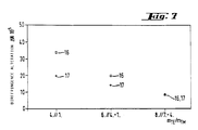
- Figure 7 is a plot of birefringence alteration ⁇ N eff .10 ⁇ 5 versus various index matching modes, m TE /m TM , for a four-layer waveguide consisting of HFDA-HFDAM-33/HFDA-HFDAM-44 on glass illustrating the increased sensitivity obtained with certain matched modes.
- Figure 8 depicts the structural arrangement for both three (not according to the invention) and four layer polyimide optical waveguides.
- one embodiment which may be used is the apparatus shown in Figure 1.
- the light of He-Ne laser (1) passes through half-wave plate (2), which polarizes the light at 45° (such that the TE and TM modes are equal) and rotates the TE and TM the polarization modes, at a particular angle of incidence, ⁇ , onto a polyimide waveguide which is composed of a substrate (4) coated with a polyimide film (3).
- the substrate is a substance which has a refractive index which is lower than that of the polyimides so the light is reflected up into the polyimide. Glass is a suitable substrate.
- 90° prisms made of heavy flint glass (5) are used to adjust the angle of incidence of the laser beam and couple the TM and TE modes into and out of the waveguide.
- the TM and TE modes coupled into the polyimide film (3) which may typically have a length of several centimeters, preferably, about 2 cm., is reflected to the surface (S) of the film where it contacts the vapor of the liquid and there is an optical anisotropic interaction which shifts the phase of the TM and TE modes.
- the TM and TE modes are coupled out of the film (3) by heavy flint glass prism (5′) and pass through an analyzer (6) which detects the alteration of the TM and TE modes.
- the analyzer (6) may be set at an angle of 90° to the direction of polarization so it can detect disturbances of the phase of the TM and TE modes.
- the detector (7) receives the signal of disturbance from the analyzer (6) and measures absolute intensity of the phase change, called the birefringence alteration, and converts the optical signal to an electrical signal which can then be displayed by any known means.
- the apparatus may be enclosed with a glass bell (8), which contains silica gel (9) in order to reduce the humidity in the apparatus which is due to the atmospheric humidity to illustrate the sensitivity of the device to changes in humidity.
- the moisture sensor should transmit a particular TE mode (e.g., TE5) and a matched TM mode (e.g., TM6) polarization simultaneously.
- TE5 and TM6 can be selected for transmittal through the waveguide by adjusting the angles of incidence ⁇ .
- the moisture sensor is constructed by utilizing the theoretical curves (Figure 2) computed from the substantive refractive index parameters for TE and TM. In this case, Figure 2 plots these curves for HFDA-ODA.
- the curves shown in Figure 2 plot the film thickness of the waveguide [ ⁇ m] against the effective refractive index N eff , of the appropriate TE and TM modes.
- These families of curves for the TE and TM polarizations represent the resonance conditions which arise from the transverse resonance condition (TRC) for plane waveguides.
- TRC transverse resonance condition
- the TE and TM modes must be matched for a particular film thickness.
- the desired property of matching of modes exists at a point of intersection of the TM and TE curves. For instance, the point of intersection indicated in Figure 2 corresponds to the matched modes for TE5 and TM6 at a film thickness of 6.1 ⁇ m for HFDA-ODA.
- Figure 3 depicts the intensity of the optical signal for modes TM5 and TE6, and TM6 and TE7, plotted against the coupling-in angle ⁇ , for an extract of the measured mode spectrum (Figure 2) of an anisotropic polyimide film HFDA-ODA having a layer thickness of 6.1 ⁇ m. It is at this film thickness as shown in Figure 2 that the TM5 and TE6 modes will be matched.
- the representation shows the TE6 mode (10) and the TM5 mode (11) which can be coupled at the same angle of incidence. The two modes overlap to such an extent that there will be sufficient overlapping of the matched modes even after the anisotropic interactions force the modes out of phase. The intensity is therefore still strong enough to be measured.
- the figure also shows that the TE7 and TM6 modes are out of phase, and therefore not matched, for the HFDA polyimide having a thickness of 6.1 ⁇ m.
- the period of time represented in Figure 3 is the initial state (of the vapor phase) before measuring the birefringence alteration.
- the overlapping of the TE and TM modes shown in Figure 3 is undertaken experimentally by preparing a waveguide having the thickness selected from the point of intersection in Figure 2.
- the film thickness is obtained by selecting a specific centrifuging speed of rotation on the photoresist centrifuge employed for producing a film from a polyimide solution.
- the surrounding atmosphere of a four-layer waveguide composed of an HFDA-HFDAM-33/HFDA-HFDAM-44 double layer was enriched with a mixture of methanol and water, whereupon the sensor reacted in the first instance to water with a specified rate constant and then to the alcohol.
- FIG. 6 depicts birefringence alteration ⁇ N eff .10 ⁇ 5 plotted against the time [s] for a three-layer waveguide (not according to the invention) using HFDA-HFDAM-33. It was observed that the curve adopts a different curve for water (14) as compared with methanol (15).
- the sensor responds to methanol with a differential sensitivity ( ⁇ N eff /t) which varies from its sensitivity to water, thereby enabling water to be separately distinguished from methanol. Time is indicated in seconds.
- C is a constant relating to the concentration of the molecule
- d is the diffusion coefficient for a particular type of molecule
- t is the time.
- the curve will be characteristic for each different molecule and will permit the identification of different molecules.
- the concentration of the molecule can be obtained by comparing the birefringence alteration at equilibrium for the molecule in the mixture (such as in Figure 6) with the corresponding birefringence alteration in the calibration curve for that molecule (such as in Figure 4). The concentration of that molecule in the sample being analyzed can be read from the calibration curve.
- the detector (7) of Figure 1 By providing the detector (7) of Figure 1 with a memory containing the data to produce calibration curves of the specific molecules to be analyzed and the capability to generate data for the birefringence alteration over time, the birefringence alteration at the equilibrium point for a particular molecule can be determined and a comparison with the calibration curve can be made to generate automatically the identity of the molecule and its concentration.
- Figure 7 shows a plot of the birefringence alteration ⁇ N eff .10 ⁇ 5 versus m TE /m TM , which is matched modes for TE and TM modes, at a relative air humidity of 42% (16) and in the evacuated condition (17) for an HFDA-HFDAM-33/HFDA-HFDAM-44 four-layer waveguide.
- the symbol, "m" represents the "mode order" with respect to TE and TM.
- surface modes is intended to refer to m TM ⁇ 2 in which the modes exhibit at the surface an especially high intensity and thus a high evanescent field.
- "space modes” show a high intensity in the interior of the film and only a weak evanescent field at the surface and m TM > 2.
- the space modes are transmitted through both layers of the polyimide.
- the four-layer polyimide sensor described in Example 3 was surrounded with a closed container.
- the volume of air enclosed (20°C, 65% RH) was then enriched with ethanol vapor. In this case, it was possible to detect less than 3 ⁇ 1/m3 C2H5OH.
- the sensitivity limit was at a level of 1 ml/m3 C3H7OH.
Abstract
Description
- The invention relates to a polyimide waveguide as an optical sensor which is used for the quantitative detection of liquids in the vapor phase, particularly, polar liquids in the vapor phase and for the detection of NH₃, "NH₄OH", NO₂ and N₂O₅.
- Polyimides are used as material for waveguides and in optoelectronics as coatings and fillings for electronic embedding material. This utility of polyimides arises from their sensitivity to "humidity" due to interactions of the vapor phase of the liquid components in the vicinity of the surface of the polyimide. Humidity measurements are usually obtained by two methods. For example, in the hair hygrometer method, the dependence of the lenght of a hair or textile fiber upon humidity is determined by means of specially prepared hairs and textile fibers, inter alia. Another method, the capacitive process utilizes a polymer film wherein the "humidity" is measured by an altered capacitance (cf. product description of an instrument for indicating moisture and temperature, model HMI 32 from the company Driesen + Kern, Tangstedt).
- Furthermore, single-layer polyimide waveguides are known as sensors using uncured polyimide and polyamide-imide films for the qualitative determination of water (cf. Appl. Phys. Lett. 52 (10), 1988).
- There accordingly existed a need to provide a measuring arrangement for the quantitative determination of "humidity", i.e., the water content of air and content of specific molecules in the vapor phase of a liquid containing those molecules.
- Surprisingly, it has been found that molecules of liquids in the vapor phase, particularly polar molecules in the vapor phase, participate in optically anisotropic interactions with polyimide surfaces and that the interactions can be detected and quantitatively measured optically. The optical sensors of the invention may also be utilized repeatedly.
- It was possible to achieve this objective by the production of a polyimide waveguide according to
claim 1 which operates as an optical sensor and has several advantages when compared with the known methods of measurement. - The measurement process has the following features:
- a) detection and measurement is accomplished optically;
- b) the detected signals can be displayed digitally;
- c) the process is a comparative measurement of the phase difference of two polarizations and is thus independent of fluctuations of the absolute value thereby enabling an accurate measurement of the phase difference;
- d) the sensor can operate also in a vacuum as well as under variable pressure conditions;
- e) the process operates for liquids, particularly polar liquids, in the vapor phase; and
- f) the process can separately distinguish water from other liquids.
- The invention relates to a polyimide waveguide which comprises at least two layers of a polyamide-imide or perfluorinated polyimide and its use for the detection of humidity.
- The object of the invention is to use the polyimide waveguide as an optical sensor for the detection of liquids in the vapor phase.
- A further object of the invention is to use the polyimide waveguide as an optical sensor for the detection of NH₃, "NH₄OH", NO₂ and N₂O₅.
- A further object of the invention is to use structured polyimide waveguides in the shape of strip waveguides, interferometer structures or directional coupler structures as optical sensors for the detection of liquids in the vapor phase.
- Polyimide waveguides comprise polyamide-imides and perfluorinated polyimides (referred to as "polyamide(s)"), for example, HFDA-ODA, HFDA-HFDAM-33, HFDA-HFDAM-44 or combinations of HFDA-HFDAM-33 and HFDA-HFDAM-44. The meaning of these abbreviations are as follows:
- HFDA:
- hexafluoruro-iso-propylene-2,2′-di-(phthalic anhydride)
- ODA:
- oxydianiline
- HFDAM-33:
- exafluoro-iso-propylidene-2,2′-di(3-aminobenzene) and
- MFDAM-44:
- hexafluoro-iso-propylidene-2,2′-di (4-aminobenzene).
- The polyimides utilized by this invention have the following structural formulae:


wherein n is an integer from 50,000 to 100,000 for HFDA-ODA, an integer from 50,000 to 80,000 for HFDA-HFDAM-33, and an integer from 50,000 to 100,000 for HFDA-HFDAM-44. - The particularly preferred waveguides include HFDA-ODA or a combination of HFDA-HFDAM-33 and HFDA-HFDAM-44.
- The polyimide waveguides are structured so that the TM and TE modes of polarized light are coupled into the polyimide layer (or layers) in phase. TM refers to the transversal magnetic polarization and TE refers to the transversal electric polarization. The TM polarization is that polarization for which the electric field "E" vector of the electromagnetic wave oscillates perpendicularly to the polyimide film surface. The TE polarization is that polarization for which the electric field "E" vector of the electromagnetic wave oscillates parallel to the polyimide film surface. An atmosphere on the surface of the polyimide layer optically interacts with the in phase TM and TE modes causing a phase disturbance (birefringence alteration) which can be optically measured to identify and quantify molecules of a liquid vapor in the atmosphere.
- The Polyimide waveguide produced for the measurement of "humidity" can be arranged using at least four layers as follows:
- Cover layer/polyimide layer/polyimide layer/substrate for a four-layered waveguide.
- Preferably, a four-layer waveguide is used. Additional layers of the polyamide may be added to form a waveguide having additional layers.
- For both the four and more layer arrangements of the polyimide waveguide, the "atmosphere", which contains the vapor phase, serves as the cover layer and the substrate is preferably glass. However, the substrate may be any substance that is transparent and has a refractive index lower than that of the polyimide layer.
- Waveguides having four layers preferably include a layer each of HFDA-HFDAM-33 and HFDA-HFDAM-44.
- HFDA-HFDAM-33 and HFDA-HFDAM-44 can be fully cured and utilized in good and stable waveguides.
- By using two layers including HFDA-HFDAM-33 and HFDA-HFDAM-44 waveguides, it is possible to obtain up to a ten-fold increase in the sensitivity of the measurement.
- One example of the four layer waveguide is composed of the following arrangement of layers:
Cover layer/an upper layer of HFDA-HFDAM-33 (referred to as "33")/a lower layer of HFDA-HFDAM-44 (referred to as "44")/substrate. The refractive indices "n" will have the following parameters:
nTE(upper layer) approximately or about equal to nTE(lower layer); and
nTM(upper layer) greater than nTM(lower layer). - In this case, nTE(33) = 1.543, nTE(44) = 1.541, nTM(33) = 1.538 and nTM(44) = 1.516;
where nTM is the refractive index for the TE polarization and nTM is that for the TM polarization. The layers (33 and 44) used to form the waveguide are distinguishable with respect to the TM polarization in that the lower layer (44) due to its lower nTM does not transmit the TM mode. Rather, the TM mode is only transmitted through the upper layer (33). However, since the nTE of both layers are about equal, the TE mode is transmitted through both layers of polyimide. In view of the shorter distance traveled by the TM mode through only the upper layer, the TM mode light intensity at the polyimide surface is increased, thereby increasing the anistropic interaction with the atmosphere and amplifying its phase shift when compared to the TE mode, which travels a longer distance through both layers and correspondingly has a less intense interaction with the atmosphere. In this way, the phase disturbance for the TM polarization at the surface is increased, leading to an increase in sensitivity (see Figure 7) of the device. - Using the optical sensor according to the invention, it is possible to detect and measure liquids in the vapor phase, for example water, C₁-C₃ alcohols, gasoline, light heating fuel oil and C₁-C₃ carboxylic acids. In addition, it is possible to detect and measure NH₃, NH₄OH, NO₂ and N₂O₅. It is preferred to use the optical sensor to detect water and C₁-C₃ alcohols or mixtures thereof. It is also preferred that the sensor be utilized to detect a single type of molecule or a mixture of two types of molecules.
- Polyimide waveguides can also be used as optical sensors for detection of liquids, in shapes such as strip waveguides, interferometer structures or directional coupler structures.
- The optical sensor may also be used to detect other physical properties (e.g., local pressure, temperature and electric fields) which influence the equilibrium between the polyimide surface and the humid atmosphere. An example of this is observed when, for constant humidity, the absorption/desorption equilibrium will change when infrared or microwave radiation is absorbed by the polyimide film. This absorption of radiation causes an increase in the local temperature which leads to a different local relative humidity at the surface. Changes in the relative humidity at the polyimide surface can be detected and measured by the present invention.
- The ability to use the polyimide waveguide as an optical sensor is derived from the interaction of molecules with the polar imide groups within the polyimide backbone. Each type of molecule in the vapor phase is related to a time constant in that each molecule is absorbed and desorbed by the polyimide waveguide over different time intervals and therefore can be distinguished in a vapor phase mixture. The intensity of the obtained anisotropy (birefringence alteration) corresponds to the concentration of that particular molecule in the vapor phase atmosphere.
- Figure 1 shows an apparatus used for measuring polar molecules in the vapor phase of a liquid in accordance with the present invention.
- Figure 2 is a plot of film thickness (µm) versus effective refractive index (Neff,) for determining at what film thickness of HFDA-ODA (not according to the invention) the mode matching for the TE and TM polarizations may be obtained.
- Figure 3 is a plot of intensity versus coupling-in angle (τ) depicting the TE/TM intersection point determined from the graph in Figure 2.
- Figure 4 is a calibration curve representing the birefringence alteration (ΔNeff.10⁻³) and its correspondence to air humidity, illustrated by the use of HFDA-ODA for the polyimide waveguide material (not according to the invention).
- Figure 5 is a plot of the time dependance of the measured birefringence alteration, ΔNeff, for water on an HFDA-ODA waveguide (not according to the invention).
- Figure 6 is a plot of the anisotropic reaction, birefringence alteration ΔNeff.10⁻⁵ versus time [s], of an HFDA-HFDAM-33 three-layer waveguide (not according to the invention) when enriched with a mixture of water and methanol.
- Figure 7 is a plot of birefringence alteration ΔNeff.10⁻⁵ versus various index matching modes, mTE/mTM, for a four-layer waveguide consisting of HFDA-HFDAM-33/HFDA-HFDAM-44 on glass illustrating the increased sensitivity obtained with certain matched modes.
- Figure 8 depicts the structural arrangement for both three (not according to the invention) and four layer polyimide optical waveguides.
- In order todetermine"humidity", one embodiment which may be used is the apparatus shown in Figure 1. The light of He-Ne laser (1) passes through half-wave plate (2), which polarizes the light at 45° (such that the TE and TM modes are equal) and rotates the TE and TM the polarization modes, at a particular angle of incidence, τ, onto a polyimide waveguide which is composed of a substrate (4) coated with a polyimide film (3). The substrate is a substance which has a refractive index which is lower than that of the polyimides so the light is reflected up into the polyimide. Glass is a suitable substrate. 90° prisms made of heavy flint glass (5) are used to adjust the angle of incidence of the laser beam and couple the TM and TE modes into and out of the waveguide. The TM and TE modes coupled into the polyimide film (3), which may typically have a length of several centimeters, preferably, about 2 cm., is reflected to the surface (S) of the film where it contacts the vapor of the liquid and there is an optical anisotropic interaction which shifts the phase of the TM and TE modes. The TM and TE modes are coupled out of the film (3) by heavy flint glass prism (5′) and pass through an analyzer (6) which detects the alteration of the TM and TE modes. The analyzer (6) may be set at an angle of 90° to the direction of polarization so it can detect disturbances of the phase of the TM and TE modes. The detector (7) receives the signal of disturbance from the analyzer (6) and measures absolute intensity of the phase change, called the birefringence alteration, and converts the optical signal to an electrical signal which can then be displayed by any known means.
- The apparatus may be enclosed with a glass bell (8), which contains silica gel (9) in order to reduce the humidity in the apparatus which is due to the atmospheric humidity to illustrate the sensitivity of the device to changes in humidity.
- In order to obtain the desired results, the moisture sensor (Figure 1) should transmit a particular TE mode (e.g., TE₅) and a matched TM mode (e.g., TM₆) polarization simultaneously. Specific polarization modes, for example TE₅ and TM₆, can be selected for transmittal through the waveguide by adjusting the angles of incidence τ.
- The moisture sensor is constructed by utilizing the theoretical curves (Figure 2) computed from the substantive refractive index parameters for TE and TM. In this case, Figure 2 plots these curves for HFDA-ODA.
- The curves shown in Figure 2 plot the film thickness of the waveguide [µm] against the effective refractive index Neff, of the appropriate TE and TM modes. These families of curves for the TE and TM polarizations, represent the resonance conditions which arise from the transverse resonance condition (TRC) for plane waveguides. In order to transmit the TE and TM modes through the polyimide film (3) so that they are in phase, the TE and TM modes must be matched for a particular film thickness. The desired property of matching of modes exists at a point of intersection of the TM and TE curves. For instance, the point of intersection indicated in Figure 2 corresponds to the matched modes for TE₅ and TM₆ at a film thickness of 6.1 µm for HFDA-ODA. It is desirable to have matched modes and thereby transmit the TE and TM modes in phase in order to measure the birefringence alteration (or phase shifting) caused by the anisotropic interaction between the waveguide and the molecules in the vapor phase of the liquid at the waveguide surface (S) as the TM and TE modes pass through the polyimide film.
- Figure 3 depicts the intensity of the optical signal for modes TM₅ and TE₆, and TM₆ and TE₇, plotted against the coupling-in angle τ, for an extract of the measured mode spectrum (Figure 2) of an anisotropic polyimide film HFDA-ODA having a layer thickness of 6.1 µm. It is at this film thickness as shown in Figure 2 that the TM₅ and TE₆ modes will be matched. The representation shows the TE₆ mode (10) and the TM₅ mode (11) which can be coupled at the same angle of incidence. The two modes overlap to such an extent that there will be sufficient overlapping of the matched modes even after the anisotropic interactions force the modes out of phase. The intensity is therefore still strong enough to be measured. The figure also shows that the TE₇ and TM₆ modes are out of phase, and therefore not matched, for the HFDA polyimide having a thickness of 6.1 µm. The period of time represented in Figure 3 is the initial state (of the vapor phase) before measuring the birefringence alteration.
- The overlapping of the TE and TM modes shown in Figure 3 is undertaken experimentally by preparing a waveguide having the thickness selected from the point of intersection in Figure 2. The film thickness is obtained by selecting a specific centrifuging speed of rotation on the photoresist centrifuge employed for producing a film from a polyimide solution.
- Forming a calibration curve for the material HFDA-ODA:
- In Figure 4 a calibration curve has been plotted which represents the birefringence alteration ΔNeff.10⁻³ at equilibrium for the material HFDA-ODA, ΔNeff = NTE6-NTM5, and has been plotted against the relative humidity RH [%] for moisture in the air. The anisotropy measurement was obtained for the entire range from 0 to 100% humidity. This calibration curve is dependent upon which polyimide waveguide and polar molecules are utilized.
- Evacuation and ventilation of a container with moist air:
- A multiplicity of intensity fluctuations was observed during the evacuation of a test vessel. When these fluctuations were evaluated, it was then possible to represent the pertinent optical birefringence alteration ΔNeff as a function of the time [s]. Figure 5 shows this fluctuation for the absorption, first period (12) (before equilibrium is reached) and the desorption, second period (13) (after equilibrium has been reached) of water on an HFDA-ODA waveguide. Equilibrium is the state at which absorption and desorption are at equilibrium or equal. Here ΔNeff is the index difference which was obtained from the phase difference of the transmitted TE and TM polarization modes or the birefringence alteration. In each instance, it was possible to associate a reaction constant, which signifies the absorption speed, with the root-type curve.
- Sensitivity measurement of an alcohol/water mixture:
- The surrounding atmosphere of a four-layer waveguide composed of an HFDA-HFDAM-33/HFDA-HFDAM-44 double layer was enriched with a mixture of methanol and water, whereupon the sensor reacted in the first instance to water with a specified rate constant and then to the alcohol.
- This is further illustrated in Figure 6, which depicts birefringence alteration ΔNeff.10⁻⁵ plotted against the time [s] for a three-layer waveguide (not according to the invention) using HFDA-HFDAM-33. It was observed that the curve adopts a different curve for water (14) as compared with methanol (15). The sensor responds to methanol with a differential sensitivity (ΔNeff/t) which varies from its sensitivity to water, thereby enabling water to be separately distinguished from methanol. Time is indicated in seconds.
- The curve for water (14) and the curve for methanol (15) are calculated using the known procedures for analyzing a diffusion process in which

- The concentration of the molecule can be obtained by comparing the birefringence alteration at equilibrium for the molecule in the mixture (such as in Figure 6) with the corresponding birefringence alteration in the calibration curve for that molecule (such as in Figure 4). The concentration of that molecule in the sample being analyzed can be read from the calibration curve.
- By providing the detector (7) of Figure 1 with a memory containing the data to produce calibration curves of the specific molecules to be analyzed and the capability to generate data for the birefringence alteration over time, the birefringence alteration at the equilibrium point for a particular molecule can be determined and a comparison with the calibration curve can be made to generate automatically the identity of the molecule and its concentration.
- Figure 7 shows a plot of the birefringence alteration ΔNeff.10⁻⁵ versus mTE/mTM, which is matched modes for TE and TM modes, at a relative air humidity of 42% (16) and in the evacuated condition (17) for an HFDA-HFDAM-33/HFDA-HFDAM-44 four-layer waveguide. The symbol, "m", represents the "mode order" with respect to TE and TM.
- Accordingly, Figure 7 shows the sensitivity of the sensor when differing mode matchings are employed. Measurements were made for 3 different mode matchings of TE and TM polarizations. The plotted ΔNeff values correspond to humidity (moisture) in air of 42% in all three cases. It is clearly possible to discern the increase in the sensitivity of measurement when using the mode matching 4/1 as compared with the combinations for higher modes 6/4 and 8/7. 4/1 represents the phase matching for mTE = 4 and mTM = 1. In the case of this matching, a TM mode, that is mTM=1, was used which is transmitted only in the upper HFDA-HFDAM-33 layer. The last mentioned mode can be designated as the "surface mode".
- The expression "surface modes" is intended to refer to mTM ≦ 2 in which the modes exhibit at the surface an especially high intensity and thus a high evanescent field. These surface modes, mTM=0,1 or 2, generally will be transmitted in the upper layer of the two polyimide layers meaning that the sensitivity of the waveguide can be increased. On the other hand, "space modes" show a high intensity in the interior of the film and only a weak evanescent field at the surface and mTM > 2. The space modes mTM=2,3,4, (etc. generally will not have a high intensity at the surface and therefore will not be as sensitive in a four-layer waveguide. The space modes are transmitted through both layers of the polyimide.
- Determination of ethanol vapors:
- The four-layer polyimide sensor described in Example 3 was surrounded with a closed container. The volume of air enclosed (20°C, 65% RH) was then enriched with ethanol vapor. In this case, it was possible to detect less than 3 µ1/m³ C₂H₅OH.
- Using the arrangement described in connection with Example 5, the sensitivity to propanol was determined.
- In this case, the sensitivity limit was at a level of 1 ml/m³ C₃H₇OH.
Claims (12)
- Polyimide waveguide as optical sensor for the determination of liquids in the vapor phase, said waveguide being adapted to contact a cover layer of liquid vapor at the surface (S) of the waveguide, characterized in, that the polyimide waveguide consists of at least two layers of a polyamide-imide or perfluorinated polyimide (3) coated onto a substrate (4) and wherein the refractive index (nTM) for the transversal magnetic polarization (TM) of the upper layer of the polyimide waveguide is greater than nTM of the lower layer and the refractive index (nTE) for the transversal electric polarization (TE) of the upper layer is about equal to nTE of the lower layer.
- Polyimide waveguide as optical sensor as claimed in claim 1, characterized in, that the sequence of layers is cover layer/HFDA-HFDAM-33/HFDA-HFDAM-44/substrate, wherein HFDA-HFDAM-33 signifies hexafluoro-iso-propylidene-2,2′-di(3-aminobenzene) and HFDA-HFDAM-44 signifies hexafluoro-iso-propylidene-2,2′-di(4-amino-benzene), the cover layer, signifies the gas space and the substrate signifies glass.
- Polyimide waveguide as optical sensor as claimed in claim 1 characterized in, that it is in the form of strip waveguides, interferometer structures or directional complex structures for the determination of liquids in the vapor phase.
- Polyimide waveguide as claimed in claim 1, characterized in, that the substrate is glass and the polyamide-imide or perfluorinated polyimide is HFDA-ODA, HFDAM-33, HFDA-HFDAM-44 or a combination of HFDA-HFDAM-33 and HFDA-HFDAM-44.
- A device for detecting the presence of and measuring the relative amount of a molecule in a vapor comprising means for directing a polarized light onto the polyimide waveguide and coupling the polarized light into said waveguide;
an area adjacent to the surface of the polyimide waveguide for receiving the vapor of the liquid, so that the vapor is in contact with said waveguide;
means for coupling the polarized light out of the polyimide waveguide, and means for measuring the intensity of the phase shift of the polarized light characterized in, that it comprises a polyimide waveguide consisting essentially of at least two layers of a polyamide-imide or perfluorinated polyimide coated onto a substrate, wherein the refractive index (nTM) for the transversal magnetic polarization (TM) of the upper layer of the polyimide waveguide is greater than nTM of the lower layer and the refractive index (nTE) for the transversal electric polarization (TE) of the upper layer is about equal to nTE of the lower layer. - The device as claimed in claim 5, characterized in, that means for directing a polarized light include means for directing TM and TE modes of said polarized light.
- The device as claimed in claim 5, characterized in, that means for directing the polarized light include means for directing TM and TE modes of said polarized light at an angle of about 45°.
- The device as claimed in claim 7, characterized in, that the substrate has a refractive index which is lower than that of the polyamide-imide of perfluorinated polyimide.
- The device as claimed in claim 8, characterized in, that the polyamide-imide or perfluorinated polyimide is selected from the groups consisting of HFDA-ODA, HFDA-HFDAM-33, HFDA-HFDAM-44 or combinations of HFDA-HFDAM-33 and HFDA-HFDAM-44.
- Use of a polyimide waveguide as optical sensor as claimed in claim 1 for the determination of water, C₁-C₃-alcohols, gasoline, light heating fuel oil and C₁-C₃ carboxylic acids in the vapor phase.
- Use of a polyimide waveguide as optical sensor as claimed in claim 1 for the determination of NH₃, "NH₄OH", NO₂ and N₂O₅.
- Use of a polyimide waveguide as claimed in claims 10 and 11 characterized in, that it is used for the modulation or measurement of influences, which have an effect on the equilibrium at the polyimide surface and the measurement space, such as pressure fluctuations, electric fields and microwaves.
Applications Claiming Priority (3)
| Application Number | Priority Date | Filing Date | Title |
|---|---|---|---|
| DE3926604A DE3926604A1 (en) | 1989-08-11 | 1989-08-11 | POLYIMIDE WAVE GUIDE AS OPTICAL SENSORS |
| DE3926604 | 1989-08-11 | ||
| PCT/EP1990/001327 WO1991002239A1 (en) | 1989-08-11 | 1990-08-11 | Polyimide waveguides as optical sensors |
Publications (2)
| Publication Number | Publication Date |
|---|---|
| EP0486597A1 EP0486597A1 (en) | 1992-05-27 |
| EP0486597B1 true EP0486597B1 (en) | 1994-09-14 |
Family
ID=6386968
Family Applications (1)
| Application Number | Title | Priority Date | Filing Date |
|---|---|---|---|
| EP90912918A Expired - Lifetime EP0486597B1 (en) | 1989-08-11 | 1990-08-11 | Polyimide waveguides as optical sensors |
Country Status (10)
| Country | Link |
|---|---|
| US (1) | US5094517A (en) |
| EP (1) | EP0486597B1 (en) |
| JP (1) | JPH03183935A (en) |
| KR (1) | KR920004868A (en) |
| CN (1) | CN1049720A (en) |
| AT (1) | ATE111600T1 (en) |
| AU (1) | AU6280190A (en) |
| CA (2) | CA2023072A1 (en) |
| DE (2) | DE3926604A1 (en) |
| WO (1) | WO1991002239A1 (en) |
Families Citing this family (37)
| Publication number | Priority date | Publication date | Assignee | Title |
|---|---|---|---|---|
| US5168542A (en) * | 1991-10-09 | 1992-12-01 | The Boeing Company | Low loss channel waveguide and method for making the same |
| US5315673A (en) * | 1992-03-09 | 1994-05-24 | Transducer Research, Inc. | Optical waveguide vapor sensor |
| US5483346A (en) * | 1994-04-11 | 1996-01-09 | Butzer; Dane C. | Polarization based optical sensor utilizing total internal reflection |
| JP2807777B2 (en) * | 1994-09-09 | 1998-10-08 | 工業技術院長 | Optical absorption spectrum measuring device using slab optical waveguide |
| US5577137A (en) * | 1995-02-22 | 1996-11-19 | American Research Corporation Of Virginia | Optical chemical sensor and method using same employing a multiplicity of fluorophores contained in the free volume of a polymeric optical waveguide or in pores of a ceramic waveguide |
| US5745231A (en) * | 1995-06-12 | 1998-04-28 | American Research Corporation Of Virginia | Method of fluorescence analysis comprising evanescent wave excitation and out-of-plane photodetection |
| JP3738469B2 (en) * | 1995-07-27 | 2006-01-25 | 日立化成工業株式会社 | Polyimide and optical component using the same |
| US7187795B2 (en) * | 2001-09-27 | 2007-03-06 | Cummins-Allison Corp. | Document processing system using full image scanning |
| US6149591A (en) * | 1997-02-21 | 2000-11-21 | Duke University | Refractometric devices especially adapted for the in vivo detection of refractive indices of cervical mucus |
| DE19716252A1 (en) * | 1997-04-18 | 1998-10-22 | Conducta Endress & Hauser | Optical sensor |
| EP0988517A4 (en) * | 1997-06-10 | 2003-03-19 | Calspan Corp | Detection of chemical agent materials using a sorbent polymer and fluorescent probe |
| US6850315B1 (en) | 1998-08-26 | 2005-02-01 | The Board Of Governors For Higher Education State Of Rhode Island And Providence Plantations | Intensity-based optical waveguide sensor |
| US6300638B1 (en) | 1998-11-12 | 2001-10-09 | Calspan Srl Corporation | Modular probe for total internal reflection fluorescence spectroscopy |
| US6438279B1 (en) * | 1999-01-07 | 2002-08-20 | Cornell Research Foundation, Inc. | Unitary microcapiliary and waveguide structure and method of fabrication |
| EP1256819A4 (en) * | 1999-10-28 | 2006-08-23 | Sharp Kk | Optical component and method of manufacturing thick polyimide film |
| GB9927248D0 (en) | 1999-11-18 | 2000-01-12 | Farfield Sensors Ltd | Sensor device |
| KR20010087502A (en) | 2000-03-07 | 2001-09-21 | 윤종용 | Optical polyimide monomer, optical polyimide compound and fabrication method thereof |
| EP1221581A1 (en) * | 2001-01-04 | 2002-07-10 | Universität Stuttgart | Interferometer |
| KR20020082514A (en) * | 2001-04-24 | 2002-10-31 | 주식회사 씨앤케이 | Optical correlator |
| US6603917B2 (en) | 2001-11-07 | 2003-08-05 | Photon-X, Inc | Planar optical waveguide with core barrier |
| US6917749B2 (en) | 2001-11-07 | 2005-07-12 | Photon-X, Llc | Polymer optical waveguides on polymer substrates |
| US6903815B2 (en) * | 2001-11-22 | 2005-06-07 | Kabushiki Kaisha Toshiba | Optical waveguide sensor, device, system and method for glucose measurement |
| US20050018944A1 (en) * | 2003-07-25 | 2005-01-27 | Mozdy Eric J. | Polarization modulation interrogation of grating-coupled waveguide sensors |
| DE102005055288A1 (en) * | 2005-10-17 | 2007-04-19 | Universität Duisburg-Essen | Sensor and method for the optical detection of a chemical substance |
| AU2007289057C1 (en) | 2006-09-01 | 2014-01-16 | Pacific Biosciences Of California, Inc. | Substrates, systems and methods for analyzing materials |
| US8207509B2 (en) | 2006-09-01 | 2012-06-26 | Pacific Biosciences Of California, Inc. | Substrates, systems and methods for analyzing materials |
| EP4325209A2 (en) | 2008-09-16 | 2024-02-21 | Pacific Biosciences Of California, Inc. | Integrated optical device |
| JP2010223817A (en) * | 2009-03-24 | 2010-10-07 | Soka Univ | Ethanol sensor and ethanol measurement system using the same |
| AU2011217862B9 (en) | 2010-02-19 | 2014-07-10 | Pacific Biosciences Of California, Inc. | Integrated analytical system and method |
| US8994946B2 (en) | 2010-02-19 | 2015-03-31 | Pacific Biosciences Of California, Inc. | Integrated analytical system and method |
| US9372308B1 (en) | 2012-06-17 | 2016-06-21 | Pacific Biosciences Of California, Inc. | Arrays of integrated analytical devices and methods for production |
| US9223084B2 (en) | 2012-12-18 | 2015-12-29 | Pacific Biosciences Of California, Inc. | Illumination of optical analytical devices |
| WO2014130900A1 (en) | 2013-02-22 | 2014-08-28 | Pacific Biosciences Of California, Inc. | Integrated illumination of optical analytical devices |
| CA2959518A1 (en) | 2014-08-27 | 2016-03-03 | Pacific Biosciences Of California, Inc. | Arrays of integrated analytical devices |
| EP4220256A1 (en) | 2015-03-16 | 2023-08-02 | Pacific Biosciences of California, Inc. | Analytical system comprising integrated devices and systems for free-space optical coupling |
| WO2016201387A1 (en) | 2015-06-12 | 2016-12-15 | Pacific Biosciences Of California, Inc. | Integrated target waveguide devices and systems for optical coupling |
| US10407296B2 (en) | 2016-10-12 | 2019-09-10 | Knappco Corporation | Optical fluid sensors for cross contamination control systems |
Family Cites Families (2)
| Publication number | Priority date | Publication date | Assignee | Title |
|---|---|---|---|---|
| JPS5595902A (en) * | 1978-11-30 | 1980-07-21 | Daicel Chem Ind Ltd | Optical fiber for transmission |
| US5120131A (en) * | 1988-02-14 | 1992-06-09 | Walter Lukosz | Method and apparatus for selecting detection of changes in samples by integrated optical interference |
-
1989
- 1989-08-11 DE DE3926604A patent/DE3926604A1/en not_active Withdrawn
-
1990
- 1990-08-09 KR KR1019900012196A patent/KR920004868A/en unknown
- 1990-08-10 CA CA002023072A patent/CA2023072A1/en not_active Abandoned
- 1990-08-10 JP JP2213612A patent/JPH03183935A/en active Pending
- 1990-08-10 CN CN90106947A patent/CN1049720A/en active Pending
- 1990-08-10 US US07/565,503 patent/US5094517A/en not_active Expired - Lifetime
- 1990-08-11 DE DE69012573T patent/DE69012573T2/en not_active Expired - Fee Related
- 1990-08-11 EP EP90912918A patent/EP0486597B1/en not_active Expired - Lifetime
- 1990-08-11 AU AU62801/90A patent/AU6280190A/en not_active Abandoned
- 1990-08-11 CA CA002064831A patent/CA2064831A1/en not_active Abandoned
- 1990-08-11 WO PCT/EP1990/001327 patent/WO1991002239A1/en active IP Right Grant
- 1990-08-11 AT AT90912918T patent/ATE111600T1/en not_active IP Right Cessation
Also Published As
| Publication number | Publication date |
|---|---|
| EP0486597A1 (en) | 1992-05-27 |
| DE69012573T2 (en) | 1995-02-23 |
| CA2064831A1 (en) | 1991-02-12 |
| DE69012573D1 (en) | 1994-10-20 |
| ATE111600T1 (en) | 1994-09-15 |
| AU6280190A (en) | 1991-03-11 |
| CA2023072A1 (en) | 1991-02-12 |
| JPH03183935A (en) | 1991-08-09 |
| WO1991002239A1 (en) | 1991-02-21 |
| DE3926604A1 (en) | 1991-02-14 |
| KR920004868A (en) | 1992-03-28 |
| US5094517A (en) | 1992-03-10 |
| CN1049720A (en) | 1991-03-06 |
Similar Documents
| Publication | Publication Date | Title |
|---|---|---|
| EP0486597B1 (en) | Polyimide waveguides as optical sensors | |
| US8111402B2 (en) | Optical sensing based on overlapping optical modes in optical resonator sensors and interferometric sensors | |
| Jorgenson et al. | Control of the dynamic range and sensitivity of a surface plasmon resonance based fiber optic sensor | |
| US4950074A (en) | Method of determining the refractive index of a substance and apparatus thereof | |
| Meeten | Refractive index errors in the critical-angle and the Brewster-angle methods applied to absorbing and heterogeneous materials | |
| Niggemann et al. | Remote sensing of tetrachloroethene with a micro-fibre optical gas sensor based on surface plasmon resonance spectroscopy | |
| US6137576A (en) | Optical transducers based on liquid crystalline phases | |
| Fattinger et al. | The difference interferometer: a highly sensitive optical probe for quantification of molecular surface concentration | |
| US20100075431A1 (en) | Formaldehyde detector body, formaldehyde detector, formaldehyde detection method and formaldehyde detection reagent | |
| Abdurahman et al. | Optical waveguide sensor of volatile organic compounds based on PTA thin film | |
| Gu et al. | Design optimization of a long-period fiber grating with sol–gel coating for a gas sensor | |
| Ronot-Trioli et al. | Fibre optic chemical sensor based on surface plasmon monochromatic excitation | |
| WO2002014841A1 (en) | Sensor device | |
| Podgorsek et al. | Optical detection of water/alcohol vapours by polymide lightguides | |
| Butler et al. | Development of an extended-range fiber optic pH sensor using evanescent wave absorption of sol-gel-entrapped pH indicators | |
| JP2894829B2 (en) | Polyimide waveguide as optical sensor | |
| Räty et al. | Measurement of refractive index of liquids using s-and p-polarized light | |
| Katerkamp et al. | Micro-chemical sensors based on fiber-optic excitation of surface plasmons | |
| Peiponen et al. | Optical constants of industrial liquids obtained by phase retrieval from reflectometric and surface-plasmon-resonance data | |
| Hanisch et al. | Origin of optical anisotropy in planar polymer waveguides | |
| CN112577928B (en) | Design method of high-sensitivity chiral molecule detection structure based on TDBCs-Kretschmann | |
| Ingenhoff et al. | Spectral interferometric sensors for gases and liquids using integrated optical devices | |
| JP4098603B2 (en) | Optical sensor | |
| CN111795947B (en) | Plasmon waveguide sensor with resonant cavity and methods of use and manufacture thereof | |
| JP3441056B2 (en) | Cell for infrared absorption measurement using silicon waveguide with concentrated film |
Legal Events
| Date | Code | Title | Description |
|---|---|---|---|
| PUAI | Public reference made under article 153(3) epc to a published international application that has entered the european phase |
Free format text: ORIGINAL CODE: 0009012 |
|
| 17P | Request for examination filed |
Effective date: 19920128 |
|
| AK | Designated contracting states |
Kind code of ref document: A1 Designated state(s): AT BE CH DE DK ES FR GB IT LI LU NL SE |
|
| 17Q | First examination report despatched |
Effective date: 19931220 |
|
| GRAA | (expected) grant |
Free format text: ORIGINAL CODE: 0009210 |
|
| AK | Designated contracting states |
Kind code of ref document: B1 Designated state(s): AT BE CH DE DK ES FR GB IT LI LU NL SE |
|
| PG25 | Lapsed in a contracting state [announced via postgrant information from national office to epo] |
Ref country code: NL Effective date: 19940914 Ref country code: ES Free format text: THE PATENT HAS BEEN ANNULLED BY A DECISION OF A NATIONAL AUTHORITY Effective date: 19940914 Ref country code: DK Effective date: 19940914 Ref country code: BE Effective date: 19940914 Ref country code: AT Effective date: 19940914 |
|
| REF | Corresponds to: |
Ref document number: 111600 Country of ref document: AT Date of ref document: 19940915 Kind code of ref document: T |
|
| REF | Corresponds to: |
Ref document number: 69012573 Country of ref document: DE Date of ref document: 19941020 |
|
| ITF | It: translation for a ep patent filed |
Owner name: ING. C. GREGORJ S.P.A. |
|
| PG25 | Lapsed in a contracting state [announced via postgrant information from national office to epo] |
Ref country code: SE Effective date: 19941214 |
|
| ET | Fr: translation filed | ||
| NLV1 | Nl: lapsed or annulled due to failure to fulfill the requirements of art. 29p and 29m of the patents act | ||
| PLBE | No opposition filed within time limit |
Free format text: ORIGINAL CODE: 0009261 |
|
| STAA | Information on the status of an ep patent application or granted ep patent |
Free format text: STATUS: NO OPPOSITION FILED WITHIN TIME LIMIT |
|
| PG25 | Lapsed in a contracting state [announced via postgrant information from national office to epo] |
Ref country code: LU Free format text: LAPSE BECAUSE OF NON-PAYMENT OF DUE FEES Effective date: 19950831 Ref country code: LI Effective date: 19950831 Ref country code: CH Effective date: 19950831 |
|
| 26N | No opposition filed | ||
| REG | Reference to a national code |
Ref country code: CH Ref legal event code: PL |
|
| REG | Reference to a national code |
Ref country code: GB Ref legal event code: IF02 |
|
| PGFP | Annual fee paid to national office [announced via postgrant information from national office to epo] |
Ref country code: GB Payment date: 20040730 Year of fee payment: 15 |
|
| PGFP | Annual fee paid to national office [announced via postgrant information from national office to epo] |
Ref country code: DE Payment date: 20040805 Year of fee payment: 15 |
|
| PGFP | Annual fee paid to national office [announced via postgrant information from national office to epo] |
Ref country code: FR Payment date: 20040809 Year of fee payment: 15 |
|
| PG25 | Lapsed in a contracting state [announced via postgrant information from national office to epo] |
Ref country code: IT Free format text: LAPSE BECAUSE OF NON-PAYMENT OF DUE FEES;WARNING: LAPSES OF ITALIAN PATENTS WITH EFFECTIVE DATE BEFORE 2007 MAY HAVE OCCURRED AT ANY TIME BEFORE 2007. THE CORRECT EFFECTIVE DATE MAY BE DIFFERENT FROM THE ONE RECORDED. Effective date: 20050811 Ref country code: GB Free format text: LAPSE BECAUSE OF NON-PAYMENT OF DUE FEES Effective date: 20050811 |
|
| PG25 | Lapsed in a contracting state [announced via postgrant information from national office to epo] |
Ref country code: DE Free format text: LAPSE BECAUSE OF NON-PAYMENT OF DUE FEES Effective date: 20060301 |
|
| GBPC | Gb: european patent ceased through non-payment of renewal fee |
Effective date: 20050811 |
|
| PG25 | Lapsed in a contracting state [announced via postgrant information from national office to epo] |
Ref country code: FR Free format text: LAPSE BECAUSE OF NON-PAYMENT OF DUE FEES Effective date: 20060428 |
|
| REG | Reference to a national code |
Ref country code: FR Ref legal event code: ST Effective date: 20060428 |