EP0496586A1 - Chip-type electronic element supplying apparatus - Google Patents
Chip-type electronic element supplying apparatus Download PDFInfo
- Publication number
- EP0496586A1 EP0496586A1 EP92300514A EP92300514A EP0496586A1 EP 0496586 A1 EP0496586 A1 EP 0496586A1 EP 92300514 A EP92300514 A EP 92300514A EP 92300514 A EP92300514 A EP 92300514A EP 0496586 A1 EP0496586 A1 EP 0496586A1
- Authority
- EP
- European Patent Office
- Prior art keywords
- tape
- chip
- take
- type electronic
- disposed
- Prior art date
- Legal status (The legal status is an assumption and is not a legal conclusion. Google has not performed a legal analysis and makes no representation as to the accuracy of the status listed.)
- Granted
Links
Images


Classifications
-
- H—ELECTRICITY
- H05—ELECTRIC TECHNIQUES NOT OTHERWISE PROVIDED FOR
- H05K—PRINTED CIRCUITS; CASINGS OR CONSTRUCTIONAL DETAILS OF ELECTRIC APPARATUS; MANUFACTURE OF ASSEMBLAGES OF ELECTRICAL COMPONENTS
- H05K13/00—Apparatus or processes specially adapted for manufacturing or adjusting assemblages of electric components
- H05K13/04—Mounting of components, e.g. of leadless components
- H05K13/0417—Feeding with belts or tapes
- H05K13/0419—Feeding with belts or tapes tape feeders
-
- Y—GENERAL TAGGING OF NEW TECHNOLOGICAL DEVELOPMENTS; GENERAL TAGGING OF CROSS-SECTIONAL TECHNOLOGIES SPANNING OVER SEVERAL SECTIONS OF THE IPC; TECHNICAL SUBJECTS COVERED BY FORMER USPC CROSS-REFERENCE ART COLLECTIONS [XRACs] AND DIGESTS
- Y10—TECHNICAL SUBJECTS COVERED BY FORMER USPC
- Y10T—TECHNICAL SUBJECTS COVERED BY FORMER US CLASSIFICATION
- Y10T29/00—Metal working
- Y10T29/53—Means to assemble or disassemble
- Y10T29/5313—Means to assemble electrical device
- Y10T29/53174—Means to fasten electrical component to wiring board, base, or substrate
- Y10T29/53178—Chip component
Definitions
- the present invention relates to a chip-type electronic element supplying apparatus for use in an apparatus for automatically mounting chip-type electronic elements on a printed circuit board.
- Chip-type electronic elements 1a formed variously as shown in Figs. 12A to 12B are accommodated in recessed portions 2a formed in a carrier tape 2 which has conveyance holes 3 formed at predetermined intervals on either side of the carrier tape 2 as shown in Fig. 13.
- a taped electronic element group 5 is supplied to a user in a state where it is covered with a cover tape 4 and wound around a reel 6.
- the apparatus (omitted from illustration) for automatically mounting electronic elements is an apparatus arranged to sequentially take out the chip-type electronic elements 1 from the reel 6 so that they are then mounted on a circuit board.
- the chip-type electronic element supplying apparatus is a portion of the above-described apparatus for automatically mounting electronic elements.
- Fig. 14 is a perspective view which illustrates a related-art chip-type electronic element supplying apparatus.
- a carrier tape 2 taken out from the above-described reel 6 is guided to a feeding ratchet 25 so that a multiplicity of hooking claws 26 secured to the above-described feeding ratchet 25 are sequentially fastened to conveyance holes 3 formed in the carrier tape 2 when the feeding ratchet 25 is rotated.
- the carrier tape 2 is conveyed while being guided along the feeding ratchet 25 by a tape retainer 22 disposed above the feeding ratchet 25.
- the above-described cover tape 4 is turned by an angle of about 180° and is taken out in a direction opposite to the direction in which the carrier tape 2 is fed, at a position of a slip D formed in a slightly upstream (adjacent to the reel 6) of an opening portion C which is formed in the above-described tape retainer 22 and through which the electronic elements are taken out so that the cover tape 4 is separated from its carrier tape 2.
- the leading portion of the separated cover tape 4 is wound around a take-up reel 27.
- the above-described opening portion C through which the electronic elements are taken out is opened when a shutter 20 is moved in a direction designated by an arrow Y2 which opposes a direction designated by an arrow Y1 via a reverse-rotation lever 11 disposed between a feeding lever 28 and the shutter 20 by an action of a kicker (omitted from illustration) provided for the apparatus (omitted from illustration) for automatically mounting electronic elements in synchronization with the action of the apparatus for automatically mounting electronic elements. That is, the above-described shutter 20 is movably fastened to the tape retainer 22 in such a manner that the shutter 20 covers the opening C through which the electronic elements are taken out when the feeding lever 28 is pulled in the direction Y2 by a tension spring 32.
- a feeding ratchet lever 14 connected to the above-described feeding lever 28 by a connection pin 13 and arranged to act in synchronization with the action of the feeding lever 28 is moved downwards.
- a feeding ratchet claw 16 fastened to the feeding ratchet lever 14 via a supporting point 15 is returned by one pitch in a direction which opposes the direction of the rotation of the above-described feeding ratchet 25.
- a movable lever 18 having a supporting shaft 17 which is commonly used as the supporting shaft for the feeding lever 28 is upwards moved via a connection pin 19.
- a take-up ratchet lever 35 is upwards moved around a rotational shaft 30 of the above-described take-up reel 27 by a connection rod 24 which establishes a connection between the movable lever 18 and the take-up ratchet lever 35.
- a take-up ratchet claw 23 fastened to the ratchet lever 35 via a supporting point 36 is returned by one or plural pitches in a direction which opposes a direction in which the take-up ratchet 29 is rotated.
- the feeding lever 28 When the pushing force given to the feeding lever 28 from the above-described kicker is released in a state shown in Fig. 14, the feeding lever 28 is returned in the direction Y2 by the urging force of the tension spring 32. As a result, the feeding ratchet lever 14 is moved upwards and the feeding ratchet claw 26 upwards pushes the feeding ratchet 25 in synchronization with the above-described upward movement of the feeding ratchet lever 14 so that the feeding ratchet 25 is rotated by a predetermined number of pitches in the tape feeding direction. Then, the hooking claw 26 secured to the feeding ratchet 25 conveys the carrier tape 2 by a predetermined number of pitches in the direction Y1.
- the shutter 20 is, similarly to the carrier tape 2, moved in the direction Y1 via the reverse-rotation lever 11. As a result, a state where the opening portion C through which the electronic elements are taken out is covered by the shutter 20 is realized. Therefore, the carrier tape 2 is moved in a state where the above-described electronic elements 1 are covered with the shutter 20. As a result, undesirable pop-out of the chip-type electronic elements 1 from the recessed portions 2a of the carrier tape 2 can be prevented.
- the feeding ratchet 29 is rotated in a direction designated by an arrow shown in Fig. 14 by the take-up ratchet claw 23 when the above-described feeding lever 28 is returned.
- the cover tape 4 separated at the slit D is wound by a take-up reel 27 to which the feeding ratchet 29 is secured by a predetermined length (a length corresponding to a predetermined pitch of feeding of the carrier tape 2).
- the movable lever 18 is downwards moved when the feeding lever 28 is returned in the direction Y2.
- the movable lever 18 is given the urging force determined by the tension spring so as to keep an interval from the connection pin 19.
- the structure is constituted in such a manner that predetermined rotational force is always given to the take-up reel 27 by the tension spring 31 via the connection rod 24, the feeding ratchet claw 23 and the feeding ratchet 29 to separate the cover tape 4.
- Reference numeral 10 represents a front cover
- 21 represents a carrier tape receiving plate
- 12 represents a carrier tape discharge port.
- the related-art chip-type electronic element supplying apparatus constituted as shown in Fig. 13 encounters a problem in that there is a limit present in reducing the thickness of the supply apparatus due to the unsatisfactory rigidity of the body of the supply apparatus and thereby the electronic elements cannot stably be supplied.
- An object of the present invention is to provide a chip-type electronic element supplying apparatus capable of overcoming the above-described conventional problems and thereby capable of improving the mounting tactic.
- a chip-type electronic element supplying apparatus comprising: a body frame; a plurality of reels to each of which is constituted by applying a cover tape to a carrier tape having accommodating portions that accommodate chip-type electronic elements at predetermined intervals and wound up; reel side plates which are disposed at an end portion of the body frame and to which a plurality of the reels are rotatively fastened; a recessed portion which is formed in another end portion of the body frame and in which tape feeding mechanisms, each of which has a feeding claw which is engaged to the carrier tape carrying the taped electronic elements and taken out from the reel in order to intermittently convey the carrier tape, are disposed by the number corresponding to the number of the reels; tape retainers disposed above the feeding mechanism; a cover tape take-up portion for taking out the cover tape separated from the carrier tape by means of a cut portion to a portion of the taper retainer to take up the cover tape, the cover-tape take-up portion being
- the necessity of reducing the thickness of the chip-type electronic element supplying apparatus can be eliminated and thereby the rigidity of the body frame can be maintained satisfactorily strong, causing an effect to be obtained in that the mounting tactics can be improved.
- Fig. 1 is a perspective view which illustrates an embodiment of a chip-type electronic element supplying apparatus according to the present invention.
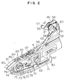
- Fig. 2 is an enlarged perspective view which illustrates an essential portion of the apparatus and
- Fig. 3 is a front elevational view which illustrates the same. Since the structure arranged in such a manner that a taped electronic group 5 constituted by accommodating chip-type electronic elements 1 in recessed portions 2a of a carrier tape 2 before they are sealed by a cover tape 4 is wound around a reel 6 is the same as the above-described structure, the same reference numerals are given to them and their specific descriptions will be omitted here.
- reel side plates 41 are fastened to an end portion of a body frame 40 which is made of an aluminum alloy or the like.
- Each of the reel side plates 41 has a size which enables the two reels 6 to be fastened in its longitudinal direction.
- the reel side plate 41 has a stepped portion 42 for the purpose of fastening the front and the rear reels 6 while deviating them by a degree corresponding to the width of the carrier tape 2.
- reel shafts 43 and 44 to which the two reels 6 are fastened are secured to the above-described reel side plates 41 so that the reels 6 are rotatably fastened to the reel shafts 43 and 44.
- reel retainers 45 and 46 for holding the corresponding outer surfaces of the reels 6 respectively fastened to the reel shafts 43 and 44 are disposed in the upper portion of an intermediate portion of the reel side plates 41.
- tape guide plates 47 and 48 each of which is formed into a shape to suit the outer surface of the reel 6 are disposed in the lower portion of an intermediate portion of the reel side plate 41.
- a separation plate 49 which halves the width of the body frame 40 is fastened to the top surface of an intermediate portion of the body frame 40.
- a reel shaft 50 is disposed in the upper portion of the above-described separation plate 49 in such a manner that the reel shaft 50 penetrates into the separation plate 49.
- two take-up reels 51 and 52 are rotatably fastened to the two end portions of the reel shaft 50 in such a manner that the two take-up reels 51 and 52 hold the separation plate 49.
- Each of the above-described take-up reels 51 and 52 is formed into a shape having a large flange adjacent to the separation plate 49 so as to form take-up ratchets 53 and 54 each having a gear portion formed on the outer surface of the flange.
- a supporting shaft 55 is disposed in the upper portion of the separation plate 49, the supporting shaft 55 holding two drive levers 56, 57 and two take-up ratchet levers 58 which are pivotally fastened in such a manner that they hold therebetween the separation plate 49.
- the above-described drive levers 56, 57, and the take-up ratchet levers 58 are arranged to act in association with one another by the action of a connection pin 59.
- a feeding ratchet claw 60 is connected to the front portion of each of the above-described take-up ratchet lever 58, the feeding ratchet claws 60 being engaged to the take-up ratchets 53 and 54 of the take-up reels 51 and 52.
- a tension spring 61 is arranged between the take-up ratchet levers 58, the tension spring 61 acting to rotate and restore the drive lever 56 or 57 in a direction designated by an arrow Y2 when the drive lever 56 or 57 is rotated in a direction designated by an arrow Y1.
- reverse-rotation protection claws 62 are disposed on the two sides of the above-described separation plate 49, the reverse-rotation protection claws 62 being always engaged to the take-up ratchets 53 and 54 of the above-described take-up reels 51 and 52 to check the reverse rotation of the take-up reels 51 and 52.
- cover tape guide rollers 63 are disposed on the two sides of an intermediate portion of the above-described separation plate 49, the cover tape guide rollers 63 acting to guide the cover tapes 4.
- a guide plate 64 is disposed on either side of the lower portion of the separation plate 49, the guide plate 64 acting to guide the taped electronic group 5 drawn out from the reel 6 disposed on the front stage.
- connection rings 65 and 66 are respectively connected to the above-described drive levers 56 and 57, the connection rings 65 and 66 extending to a recessed portion 67 formed in the front portion of the body frame 40. That is, the connection rings 65 and 66 pass through a slit 68 formed in the central portion of the top surface of the body frame 40 before the leading portions of the connection rings 65 and 66 are introduced into a recessed portion 67. Then, the above-described leading portions are connected to end portions of the right and left reverse-rotation levers 70 rotatively fastened to the support shaft 69.
- a tension spring 71 is arranged between the above-described reverse-rotation levers 70, the tension spring 71 acting to rotate and restore the reverse-rotation lever 70 after it has been rotated by the rotations of the drive levers 56 and 57 transmitted via the connection rings 65 and 66. Furthermore, a connection lever 72 is connected to the above-described reverse-rotation lever 70. The front portion of the above-described connection lever 72 is connected to a feeding ratchet lever 75 positioned in the recessed portion 67 and fastened together with a feeding ratchet 74 rotatively fastened to a supporting shaft 73.
- the above-described feeding ratchet lever 75 has a ratchet claw 76 to be engaged to the above-described feeding ratchet 74 and acting to intermittently rotate the feeding ratchet 74. Furthermore, a reverse-rotation prevention lever 77 is disposed on the outer surface of the feeding ratchet 74 in such a manner that the reverse-rotation prevention lever 77 is always engaged to the feeding ratchet 74 by the urging force generated by a spring 78.
- a carrier tape feeding ratchet wheel 79 is integrally formed with the above-described feeding ratchet 74 in such a manner that a portion of it projects over the top surface of the leading portion of the body frame 40 so as to convey the carrier tape 2 in such a way that it is engaged to a conveyance hole 3 formed in the carrier tape 2.
- Tape retainers 80 and 81 are fastened to the top surface of the leading portion of the body frame 40, the tape retainers 80 and 81 acting to guide the taped electronic element groups 5 respectively supplied from the reels 6 after they are separated from each other by the separation plate 49 in such a manner that they are engaged to the above-described carrier tape feeding ratchet wheel 79.
- Each of the tape retainers 80 and 81 has a slit 82 and an opening portion 83 so as to take out the cover tape 4 separated from the carrier tape 2 through the above-described slit 82 before it is guided by the above-described cover tape guide roller 63. As a result, the cover tapes 4 are wound around the take-up reels 51 and 52.
- the opening portions 83 respectively formed in the tape retainers 80 and 81 disposed in front of the above-described slits 82 serve as portions through which the chip-type electronic elements 1 accommodated in the recessed portion 2a of the carrier tape 2 by an adsorbing nozzle fastened to an electronic-element fastening apparatus.
- Shutters 84 and 85 are movably disposed on the top surfaces of the tape retainers 80 and 81, the shutters 84 and 85 respectively having fastening cut portions 86 at positions deviated from the width of the carrier tape 2 so as to be fastened to the leading portion of a connection plate 87 connected to the above-described reverse-rotation lever 70.
- the opening portions 83 formed in the tape retainers 80 and 81 are covered when the carrier tape 2 is conveyed by the carrier tape feeding ratchet wheel 79. Therefore, undesirable ejection of the chip-type electronic elements 1 through the recessed portion 2a formed in the carrier tape 2 is prevented.
- the above-described reels 6 are rotatively fastened to the reel shafts 43 and 44 fastened to the reel side plates 41 secured to the end portion of the body frame 40 in the longitudinal direction with respect to the supply direction.
- the conveyance holes 3 formed in the carrier tape 2 are caught to the carrier tape feeding ratchet wheel 79.
- the feeding ratchet lever 75 for driving the ratchet feeding claw 76 to be engaged to the feeding ratchet 74 formed integrally with the carrier tape feeding ratchet wheel 79 is driven in such a manner that the drive levers 56 and 57 are driven by an electronic-element automatic fastening apparatus via the reverse-rotation lever 70 and the connection lever 72 because the connection rings 65 and 66 are operated.
- the drive levers 56 and 57 are rotated in the direction Y1
- the carrier tape 2 is returned by one pitch in the direction opposing the feeding direction.
- the ratchet feeding claw 76 is then introduced into a portion between the teeth of the feeding ratchet 74, the carrier tape 2 is fed by a predetermined pitch by the action of the tension spring 71.
- the above-described cover tape 4 is turned by an angle of about 180° and is taken out in a direction opposite to the direction in which the carrier tape 2 is fed, at the position of the slit 82 positioned in a slightly upstream (adjacent to the reels 6) of the opening portion 83 through which the electronic elements are taken out. Then, the cover tape 4 is separated from the carrier tape 2 before it is wound around the take-up reels 51 and 52.
- the ratchet levers 53 and 54 disposed within the width of the take-up reels 51 and 52 having the same supporting shaft 55 as that of the drive levers 56 and 57 are upwards moved via the connection pin 59 secured to the drive levers 56 and 57.
- the take-up ratchets 53 and 54 disposed on the outer periphery of the flanges of the take-up reels 51 and 52 are returned by one or a plurality of pitches in the reverse direction by the feeding ratchet claw 60.
- the drive levers 56 and 57 are returned in the direction Y2 by the tension spring 71, the take-up reels 51 and 52 are rotated in the winding direction simultaneously with the sequential feeding made by predetermined pitches.
- the structure is arranged in such a manner that one body frame 40 has two systems each of which is composed of the above-described sequential mechanism system, the two sequential mechanism systems being disposed to oppose each other with respect to the fastening surface formed between two the carrier tapes 2.
- the shutters 84 and 85 disposed on the top surfaces of the two individual tape retainers 80 and 81 fastened to the body frame 40 are connected to the above-described drive levers 56 and 57 by the reverse lever 70 and the connection plate 87.
- the opening portion 83 through which the electronic elements are taken out is covered and the carrier tape 2 is fed by predetermined pitches in a state where the chip-type electronic elements 1 are covered by the shutters 84 and 85. Therefore, undesirable pop-out of the chip-type electronic elements 1 from the recessed portion 2a formed in the carrier tape 2 can be prevented.
- the fastening cut portion 86 is formed on the right end surface of each of the shutters 84 and 85 while being deviated from the width of the carrier tape 2.
- the leading portion of the above-described connection plate 87 is inserted into the above-described fastening cut portion 86 and the shutters 84 and 85 are driven. Therefore, the width of the shutter mechanism can be reduced.
- the reels 6 may be disposed as shown in Fig. 4 in such a manner that two reels 6 are longitudinally disposed and another reel is disposed below the two reels 6.
- Another structure as shown in Fig. 5 may be employed in which two reels 6 are disposed vertically.
- a structure as shown in Fig. 6 may be employed in which the take-up reels 51 and 52 are vertically disposed.
- Other structures as shown in Figs. 7 and 8 may be employed in each of which a plurality of reels 6 are disposed in parallel with respect to the supply direction.
- a structure as shown in Fig. 9 may be employed in which the drive levers 56 and 57 are disposed adjacent to the recessed portion 67 formed in the body frame 40.
- a dual-type chip electronic element supplying apparatus can be constituted while making its width which is, as shown in Fig. 10, substantially the same as the width of the related-art chip-type electronic element supply apparatus. Therefore, many and various chip-type electronic elements 1 can be supplied when the structure according to the present invention is used while being combined with the apparatus for automatically mounting electronic-elements.
- the chip-type electronic element supplying apparatus enables an effect to be obtained in that a limit pitch (10 mm) can be realized which is the half of that realize by the related-art chip-type electronic element supplying apparatus (see Figs. 3 and 4). Therefore, an extremely improved chip-type electronic element supplying apparatus with which the mounting tactic of the automatic mounting apparatus can be improved can be provided. Therefore, the apparatus according to the present invention is expected to be used widely in the industrial field and thereby a significant advantage will be obtained.
Abstract
Description
- The present invention relates to a chip-type electronic element supplying apparatus for use in an apparatus for automatically mounting chip-type electronic elements on a printed circuit board.
- Chip-type electronic elements 1a formed variously as shown in Figs. 12A to 12B are accommodated in recessed
portions 2a formed in acarrier tape 2 which has conveyance holes 3 formed at predetermined intervals on either side of thecarrier tape 2 as shown in Fig. 13. Thus, a tapedelectronic element group 5 is supplied to a user in a state where it is covered with acover tape 4 and wound around areel 6. The apparatus (omitted from illustration) for automatically mounting electronic elements is an apparatus arranged to sequentially take out the chip-type electronic elements 1 from thereel 6 so that they are then mounted on a circuit board. The chip-type electronic element supplying apparatus is a portion of the above-described apparatus for automatically mounting electronic elements. - Fig. 14 is a perspective view which illustrates a related-art chip-type electronic element supplying apparatus. Referring to Fig. 14, a
carrier tape 2 taken out from the above-describedreel 6 is guided to a feeding ratchet 25 so that a multiplicity of hookingclaws 26 secured to the above-described feeding ratchet 25 are sequentially fastened to conveyance holes 3 formed in thecarrier tape 2 when the feeding ratchet 25 is rotated. Thecarrier tape 2 is conveyed while being guided along the feeding ratchet 25 by atape retainer 22 disposed above the feeding ratchet 25. The above-describedcover tape 4 is turned by an angle of about 180° and is taken out in a direction opposite to the direction in which thecarrier tape 2 is fed, at a position of a slip D formed in a slightly upstream (adjacent to the reel 6) of an opening portion C which is formed in the above-describedtape retainer 22 and through which the electronic elements are taken out so that thecover tape 4 is separated from itscarrier tape 2. The leading portion of the separatedcover tape 4 is wound around a take-up reel 27. - The above-described opening portion C through which the electronic elements are taken out is opened when a
shutter 20 is moved in a direction designated by an arrow Y₂ which opposes a direction designated by an arrow Y₁ via a reverse-rotation lever 11 disposed between afeeding lever 28 and theshutter 20 by an action of a kicker (omitted from illustration) provided for the apparatus (omitted from illustration) for automatically mounting electronic elements in synchronization with the action of the apparatus for automatically mounting electronic elements. That is, the above-describedshutter 20 is movably fastened to thetape retainer 22 in such a manner that theshutter 20 covers the opening C through which the electronic elements are taken out when thefeeding lever 28 is pulled in the direction Y₂ by atension spring 32. A feeding ratchet lever 14 connected to the above-describedfeeding lever 28 by a connection pin 13 and arranged to act in synchronization with the action of thefeeding lever 28 is moved downwards. As a result, afeeding ratchet claw 16 fastened to the feeding ratchet lever 14 via a supporting point 15 is returned by one pitch in a direction which opposes the direction of the rotation of the above-described feeding ratchet 25. - When the above-described
feeding lever 28 is moved in the direction Y₁, a movable lever 18 having a supportingshaft 17 which is commonly used as the supporting shaft for thefeeding lever 28 is upwards moved via a connection pin 19. Then, a take-up ratchet lever 35 is upwards moved around a rotational shaft 30 of the above-described take-up reel 27 by aconnection rod 24 which establishes a connection between the movable lever 18 and the take-up ratchet lever 35. As a result, a take-up ratchet claw 23 fastened to theratchet lever 35 via a supportingpoint 36 is returned by one or plural pitches in a direction which opposes a direction in which the take-up ratchet 29 is rotated. - In the above-described state in which the opening portion C through which the electronic elements are taken out is opened, an operation of adsorbing the electronic elements and an operation of mounting the same on the printed circuit board (omitted from illustration) are performed by a vacuum adsorbing head (omitted from illustration). Since, the above-described manufacturing process is not relevant to the structure of the chip-type electronic element supplying apparatus, this process is omitted here.
- When the pushing force given to the
feeding lever 28 from the above-described kicker is released in a state shown in Fig. 14, thefeeding lever 28 is returned in the direction Y₂ by the urging force of thetension spring 32. As a result, the feeding ratchet lever 14 is moved upwards and thefeeding ratchet claw 26 upwards pushes the feeding ratchet 25 in synchronization with the above-described upward movement of the feeding ratchet lever 14 so that the feeding ratchet 25 is rotated by a predetermined number of pitches in the tape feeding direction. Then, the hookingclaw 26 secured to the feeding ratchet 25 conveys thecarrier tape 2 by a predetermined number of pitches in the direction Y₁. At this time, theshutter 20 is, similarly to thecarrier tape 2, moved in the direction Y₁ via the reverse-rotation lever 11. As a result, a state where the opening portion C through which the electronic elements are taken out is covered by theshutter 20 is realized. Therefore, thecarrier tape 2 is moved in a state where the above-described electronic elements 1 are covered with theshutter 20. As a result, undesirable pop-out of the chip-type electronic elements 1 from therecessed portions 2a of thecarrier tape 2 can be prevented. - On the other hand, the
feeding ratchet 29 is rotated in a direction designated by an arrow shown in Fig. 14 by the take-up ratchet claw 23 when the above-describedfeeding lever 28 is returned. Thecover tape 4 separated at the slit D is wound by a take-up reel 27 to which thefeeding ratchet 29 is secured by a predetermined length (a length corresponding to a predetermined pitch of feeding of the carrier tape 2). At this time, the movable lever 18 is downwards moved when thefeeding lever 28 is returned in the direction Y₂. During the above-described movement process, the movable lever 18 is given the urging force determined by the tension spring so as to keep an interval from the connection pin 19. - As described above, the structure is constituted in such a manner that predetermined rotational force is always given to the take-
up reel 27 by thetension spring 31 via theconnection rod 24, the feeding ratchet claw 23 and thefeeding ratchet 29 to separate thecover tape 4. - Furthermore, the
reel 6 is inserted into the supportingshaft 8 provided for the body cover 7 so as to be held by aleaf spring 9 from the side surface. Therefore, the horizontal deviation of thereel 6 is prevented and thereel 6 is stably held so that the looseness of thecarrier tape 2 taken place at the time of feeding thereof is prevented.Reference numeral 10 represents a front cover, 21 represents a carrier tape receiving plate and 12 represents a carrier tape discharge port. - Recently, there is a desire of reducing (in particular, reducing the space between the supply apparatuses) the thickness of the chip-type electronic element supplying apparatus in order to improve the mounting tactic of the apparatus for automatically mounting electronic elements. Therefore, the related-art chip-type electronic element supplying apparatus constituted as shown in Fig. 13 encounters a problem in that there is a limit present in reducing the thickness of the supply apparatus due to the unsatisfactory rigidity of the body of the supply apparatus and thereby the electronic elements cannot stably be supplied.
- An object of the present invention is to provide a chip-type electronic element supplying apparatus capable of overcoming the above-described conventional problems and thereby capable of improving the mounting tactic.
- In order to achieve the above-described object, according to the present invention, there is provided a chip-type electronic element supplying apparatus comprising: a body frame; a plurality of reels to each of which is constituted by applying a cover tape to a carrier tape having accommodating portions that accommodate chip-type electronic elements at predetermined intervals and wound up; reel side plates which are disposed at an end portion of the body frame and to which a plurality of the reels are rotatively fastened; a recessed portion which is formed in another end portion of the body frame and in which tape feeding mechanisms, each of which has a feeding claw which is engaged to the carrier tape carrying the taped electronic elements and taken out from the reel in order to intermittently convey the carrier tape, are disposed by the number corresponding to the number of the reels; tape retainers disposed above the feeding mechanism; a cover tape take-up portion for taking out the cover tape separated from the carrier tape by means of a cut portion to a portion of the taper retainer to take up the cover tape, the cover-tape take-up portion being disposed in an intermediate portion of the body frame; and an element taking-out portion which is disposed in the front portion of the tape retainer and through which the chip-type electronic elements are taken out from the carrier tape.
- As a result of the above-described structure, the necessity of reducing the thickness of the chip-type electronic element supplying apparatus can be eliminated and thereby the rigidity of the body frame can be maintained satisfactorily strong, causing an effect to be obtained in that the mounting tactics can be improved.
- Other and further objects, features and advantages of the invention will appear more fully from the following description.
-
- Fig. 1 is a perspective view which illustrates a chip-type electronic element supplying apparatus according to the present invention;
- Fig. 2 is an enlarged perspective view which illustrates an essential portion of the same;
- Fig. 3 is a front elevational view which illustrates an essential portion of the same;
- Fig. 4 is a schematic view which illustrates another embodiment of the present invention;
- Fig. 5 is a schematic view which illustrates another embodiment of the present invention;
- Fig. 6 is a schematic view which illustrates another embodiment of the present invention;
- Fig. 7 is a plain layout view which illustrates the arrangement of the reels according to another embodiment of the present invention;
- Fig. 8 is a plain layout view which illustrates the arrangement of the reels according to another embodiment of the present invention;
- Fig. 9 is a schematic view which illustrates another embodiment of the present invention;
- Fig. 10 is a plan view which illustrates the width of the apparatus according to the present invention;
- Fig. 11 is a plan view which illustrates a conventional dual-type apparatus;
- Figs. 12a to Fig. 12d are perspective views which illustrate the chip-type electronic elements;
- Fig. 13 is a perspective view which illustrates a state in which the chip-type electronic elements are covered with a tape; and
- Fig. 14 is a perspective view which illustrates a conventional chip-type electronic element supplying apparatus.
- Preferred embodiments of the present invention will now be described. Fig. 1 is a perspective view which illustrates an embodiment of a chip-type electronic element supplying apparatus according to the present invention. Fig. 2 is an enlarged perspective view which illustrates an essential portion of the apparatus and Fig. 3 is a front elevational view which illustrates the same. Since the structure arranged in such a manner that a taped
electronic group 5 constituted by accommodating chip-type electronic elements 1 in recessedportions 2a of acarrier tape 2 before they are sealed by acover tape 4 is wound around areel 6 is the same as the above-described structure, the same reference numerals are given to them and their specific descriptions will be omitted here. - Referring to Figs. 1 to 3,
reel side plates 41 are fastened to an end portion of abody frame 40 which is made of an aluminum alloy or the like. Each of thereel side plates 41 has a size which enables the tworeels 6 to be fastened in its longitudinal direction. Furthermore, thereel side plate 41 has a steppedportion 42 for the purpose of fastening the front and therear reels 6 while deviating them by a degree corresponding to the width of thecarrier tape 2. Furthermore,reel shafts reels 6 are fastened are secured to the above-describedreel side plates 41 so that thereels 6 are rotatably fastened to thereel shafts reel retainers reels 6 respectively fastened to thereel shafts reel side plates 41. Furthermore,tape guide plates reel 6 are disposed in the lower portion of an intermediate portion of thereel side plate 41. - Furthermore, a
separation plate 49 which halves the width of thebody frame 40 is fastened to the top surface of an intermediate portion of thebody frame 40. In addition, a reel shaft 50 is disposed in the upper portion of the above-describedseparation plate 49 in such a manner that the reel shaft 50 penetrates into theseparation plate 49. Furthermore, two take-upreels reels separation plate 49. Each of the above-described take-upreels separation plate 49 so as to form take-up ratchets 53 and 54 each having a gear portion formed on the outer surface of the flange. - In addition, a supporting
shaft 55 is disposed in the upper portion of theseparation plate 49, the supportingshaft 55 holding twodrive levers separation plate 49. The above-described drive levers 56, 57, and the take-up ratchet levers 58 are arranged to act in association with one another by the action of aconnection pin 59. Furthermore, afeeding ratchet claw 60 is connected to the front portion of each of the above-described take-upratchet lever 58, the feeding ratchetclaws 60 being engaged to the take-up ratchets 53 and 54 of the take-upreels tension spring 61 is arranged between the take-up ratchet levers 58, thetension spring 61 acting to rotate and restore thedrive lever drive lever - Furthermore, reverse-
rotation protection claws 62 are disposed on the two sides of the above-describedseparation plate 49, the reverse-rotation protection claws 62 being always engaged to the take-up ratchets 53 and 54 of the above-described take-upreels reels tape guide rollers 63 are disposed on the two sides of an intermediate portion of the above-describedseparation plate 49, the covertape guide rollers 63 acting to guide thecover tapes 4. Furthermore, aguide plate 64 is disposed on either side of the lower portion of theseparation plate 49, theguide plate 64 acting to guide the tapedelectronic group 5 drawn out from thereel 6 disposed on the front stage. - In addition, connection rings 65 and 66 are respectively connected to the above-described drive levers 56 and 57, the connection rings 65 and 66 extending to a recessed
portion 67 formed in the front portion of thebody frame 40. That is, the connection rings 65 and 66 pass through aslit 68 formed in the central portion of the top surface of thebody frame 40 before the leading portions of the connection rings 65 and 66 are introduced into a recessedportion 67. Then, the above-described leading portions are connected to end portions of the right and left reverse-rotation levers 70 rotatively fastened to thesupport shaft 69. Atension spring 71 is arranged between the above-described reverse-rotation levers 70, thetension spring 71 acting to rotate and restore the reverse-rotation lever 70 after it has been rotated by the rotations of the drive levers 56 and 57 transmitted via the connection rings 65 and 66. Furthermore, aconnection lever 72 is connected to the above-described reverse-rotation lever 70. The front portion of the above-describedconnection lever 72 is connected to afeeding ratchet lever 75 positioned in the recessedportion 67 and fastened together with afeeding ratchet 74 rotatively fastened to a supportingshaft 73. The above-describedfeeding ratchet lever 75 has aratchet claw 76 to be engaged to the above-describedfeeding ratchet 74 and acting to intermittently rotate thefeeding ratchet 74. Furthermore, a reverse-rotation prevention lever 77 is disposed on the outer surface of thefeeding ratchet 74 in such a manner that the reverse-rotation prevention lever 77 is always engaged to thefeeding ratchet 74 by the urging force generated by aspring 78. - In addition, a carrier tape feeding
ratchet wheel 79 is integrally formed with the above-describedfeeding ratchet 74 in such a manner that a portion of it projects over the top surface of the leading portion of thebody frame 40 so as to convey thecarrier tape 2 in such a way that it is engaged to a conveyance hole 3 formed in thecarrier tape 2.Tape retainers body frame 40, thetape retainers electronic element groups 5 respectively supplied from thereels 6 after they are separated from each other by theseparation plate 49 in such a manner that they are engaged to the above-described carrier tape feedingratchet wheel 79. Each of thetape retainers slit 82 and anopening portion 83 so as to take out thecover tape 4 separated from thecarrier tape 2 through the above-describedslit 82 before it is guided by the above-described covertape guide roller 63. As a result, thecover tapes 4 are wound around the take-upreels - The opening
portions 83 respectively formed in thetape retainers slits 82 serve as portions through which the chip-type electronic elements 1 accommodated in the recessedportion 2a of thecarrier tape 2 by an adsorbing nozzle fastened to an electronic-element fastening apparatus.Shutters tape retainers shutters carrier tape 2 so as to be fastened to the leading portion of aconnection plate 87 connected to the above-described reverse-rotation lever 70. As a result, the openingportions 83 formed in thetape retainers carrier tape 2 is conveyed by the carrier tape feedingratchet wheel 79. Therefore, undesirable ejection of the chip-type electronic elements 1 through the recessedportion 2a formed in thecarrier tape 2 is prevented. - Then, the operation of the apparatus thus-constituted will now be described.
- First, the above-described
reels 6 are rotatively fastened to thereel shafts reel side plates 41 secured to the end portion of thebody frame 40 in the longitudinal direction with respect to the supply direction. In order to feed the tapedelectronic group 5 wound around thereel 6 by a predetermined quantity, the conveyance holes 3 formed in thecarrier tape 2 are caught to the carrier tape feedingratchet wheel 79. Thefeeding ratchet lever 75 for driving theratchet feeding claw 76 to be engaged to thefeeding ratchet 74 formed integrally with the carrier tape feedingratchet wheel 79 is driven in such a manner that the drive levers 56 and 57 are driven by an electronic-element automatic fastening apparatus via the reverse-rotation lever 70 and theconnection lever 72 because the connection rings 65 and 66 are operated. When the drive levers 56 and 57 are rotated in the direction Y₁, thecarrier tape 2 is returned by one pitch in the direction opposing the feeding direction. When theratchet feeding claw 76 is then introduced into a portion between the teeth of thefeeding ratchet 74, thecarrier tape 2 is fed by a predetermined pitch by the action of thetension spring 71. In association with the above-described sequential feeding mechanism, the above-describedcover tape 4 is turned by an angle of about 180° and is taken out in a direction opposite to the direction in which thecarrier tape 2 is fed, at the position of theslit 82 positioned in a slightly upstream (adjacent to the reels 6) of the openingportion 83 through which the electronic elements are taken out. Then, thecover tape 4 is separated from thecarrier tape 2 before it is wound around the take-upreels reels shaft 55 as that of the drive levers 56 and 57 are upwards moved via theconnection pin 59 secured to the drive levers 56 and 57. Thus, the take-up ratchets 53 and 54 disposed on the outer periphery of the flanges of the take-upreels feeding ratchet claw 60. Furthermore, when the drive levers 56 and 57 are returned in the direction Y₂ by thetension spring 71, the take-upreels body frame 40 has two systems each of which is composed of the above-described sequential mechanism system, the two sequential mechanism systems being disposed to oppose each other with respect to the fastening surface formed between two thecarrier tapes 2. - When the
carrier tape 2 is fed by predetermined pitches by the above-describedfeeding ratchet 74, theshutters individual tape retainers body frame 40 are connected to the above-described drive levers 56 and 57 by thereverse lever 70 and theconnection plate 87. As a result, the openingportion 83 through which the electronic elements are taken out is covered and thecarrier tape 2 is fed by predetermined pitches in a state where the chip-type electronic elements 1 are covered by theshutters portion 2a formed in thecarrier tape 2 can be prevented. Furthermore, the fastening cut portion 86 is formed on the right end surface of each of theshutters carrier tape 2. The leading portion of the above-describedconnection plate 87 is inserted into the above-described fastening cut portion 86 and theshutters - A variety of modifications to the above-described embodiment may be employed. The
reels 6 may be disposed as shown in Fig. 4 in such a manner that tworeels 6 are longitudinally disposed and another reel is disposed below the tworeels 6. Another structure as shown in Fig. 5 may be employed in which tworeels 6 are disposed vertically. A structure as shown in Fig. 6 may be employed in which the take-upreels reels 6 are disposed in parallel with respect to the supply direction. In addition, a structure as shown in Fig. 9 may be employed in which the drive levers 56 and 57 are disposed adjacent to the recessedportion 67 formed in thebody frame 40. - As described above, according to the present invention, a dual-type chip electronic element supplying apparatus can be constituted while making its width which is, as shown in Fig. 10, substantially the same as the width of the related-art chip-type electronic element supply apparatus. Therefore, many and various chip-type electronic elements 1 can be supplied when the structure according to the present invention is used while being combined with the apparatus for automatically mounting electronic-elements.
- As described above, the chip-type electronic element supplying apparatus according to the present invention enables an effect to be obtained in that a limit pitch (10 mm) can be realized which is the half of that realize by the related-art chip-type electronic element supplying apparatus (see Figs. 3 and 4). Therefore, an extremely improved chip-type electronic element supplying apparatus with which the mounting tactic of the automatic mounting apparatus can be improved can be provided. Therefore, the apparatus according to the present invention is expected to be used widely in the industrial field and thereby a significant advantage will be obtained.
- Although the invention has been described in its preferred form with a certain degree of particularly, it is understood that the present disclosure of the preferred form has been changed in the details of construction and the combination and arrangement of parts may be resorted to without departing from the spirit and the scope of the invention as hereinafter claimed.
Claims (5)
- A chip-type electronic element supplying apparatus comprising:
a body frame;
a plurality of reels to each of which a taped electronic element group, which is constituted by applying a cover tape to a carrier tape having accommodating portions which accommodate chip-type electronic elements at predetermined intervals, is wound;
reel side plates which are disposed at an end portion of said body frame and to which a plurality of said reels are rotatively fastened;
a recessed portion which is formed in another end portion of said body frame and in which tape feeding mechanisms, each of which has a feeding claw which is engaged to said carrier tape of said taped electronic elements taken out from said reel to intermittently convey said carrier tape, are disposed by the number corresponding to the number of said reels;
tape retainers disposed above said feeding mechanism;
a cover tape take-up portion for taking out said cover tape separated from said carrier tape by means of a cut portion to a portion of said tape retainer to take up said cover tape, said cover-tape take-up portion being disposed in an intermediate portion of said body frame; and
an element taking-out portion which is disposed in the front portion of said tape retainer and through which said chip-type electronic elements are taken out from said carrier tape. - A chip-type electronic element supplying apparatus according to Claim 1, wherein a drive lever for driving said feeding mechanism is disposed within the width of each taped element at an intermediate portion of said body frame.
- A chip-type electronic element supplying apparatus according to Claim 1, wherein take-up reels each of which is arranged in such a manner that the outer portion of at least either of its flanges is formed into a gear-like shape are used.
- A chip-type electronic element supplying apparatus according to Claim 3, wherein a drive mechanism for a take-up ratchet composed of said flange of said take-up reel of said cover-tape take-up portion is disposed within the width of said take-up reel of said cover tape take-up portion.
- A chip-type electronic element supplying apparatus according to Claim 1, wherein a connection plate for shutters for opening/closing an opening portion of an element taking-out portion is fastened to said tape retainer at a position deviated from the width of said tape for said taped electronic elements.
Applications Claiming Priority (2)
| Application Number | Priority Date | Filing Date | Title |
|---|---|---|---|
| JP3005692A JPH07114319B2 (en) | 1991-01-22 | 1991-01-22 | Chip type electronic parts supply device |
| JP5692/91 | 1991-01-22 |
Publications (2)
| Publication Number | Publication Date |
|---|---|
| EP0496586A1 true EP0496586A1 (en) | 1992-07-29 |
| EP0496586B1 EP0496586B1 (en) | 1996-01-10 |
Family
ID=11618157
Family Applications (1)
| Application Number | Title | Priority Date | Filing Date |
|---|---|---|---|
| EP92300514A Expired - Lifetime EP0496586B1 (en) | 1991-01-22 | 1992-01-21 | Chip-type electronic element supplying apparatus |
Country Status (4)
| Country | Link |
|---|---|
| US (1) | US5299902A (en) |
| EP (1) | EP0496586B1 (en) |
| JP (1) | JPH07114319B2 (en) |
| DE (1) | DE69207439T2 (en) |
Cited By (9)
| Publication number | Priority date | Publication date | Assignee | Title |
|---|---|---|---|---|
| EP0938255A2 (en) * | 1998-02-19 | 1999-08-25 | FUJI MACHINE Mfg. Co., Ltd. | Electric-component supplying method and apparatus |
| EP0967849A2 (en) * | 1998-06-24 | 1999-12-29 | FUJI MACHINE Mfg. Co., Ltd. | Electric-component supplying unit |
| WO2002041681A1 (en) * | 2000-11-14 | 2002-05-23 | Koninklijke Philips Electronics N.V. | Device for supplying electronic components to a pick-up position. |
| EP1265474A1 (en) * | 1999-11-05 | 2002-12-11 | Matsushita Electric Industrial Co., Ltd. | Method and device for part feeding and part mounting device using the method and device |
| WO2003026374A2 (en) * | 2001-09-19 | 2003-03-27 | Mydata Automation Ab | System for handling components at a component mounting machine |
| EP1307083A1 (en) * | 2000-06-30 | 2003-05-02 | Matsushita Electric Industrial Co., Ltd. | Part feeder |
| EP1981326A3 (en) * | 2007-04-11 | 2011-07-06 | ASM Assembly Systems GmbH & Co. KG | Allocation between package uptake compartment and component by means of guide element |
| EP2112067A3 (en) * | 2008-04-22 | 2013-11-06 | J+P Maschinenbau GmbH | Device for guiding a clip belt and assembly of the device |
| CN103407775A (en) * | 2013-06-19 | 2013-11-27 | 昆山市烽禾升精密机械有限公司 | Feeding machine |
Families Citing this family (58)
| Publication number | Priority date | Publication date | Assignee | Title |
|---|---|---|---|---|
| US5449265A (en) * | 1994-02-15 | 1995-09-12 | Zierick Manufacturing Corporation | Feeder and method of supplying a continuous strip of surface mount contacts to pick-and-place machine |
| US5605430A (en) * | 1994-02-15 | 1997-02-25 | Zierick Manufacturing Corporation | Feeder and method of supplying a continuous strip of surface mount contacts to surface mounting equipment |
| JP3404431B2 (en) * | 1994-07-04 | 2003-05-06 | 富士機械製造株式会社 | Electronic component supply cartridge and electronic component supply / extraction device |
| US5454900A (en) * | 1994-08-10 | 1995-10-03 | Telford Industries Pte Ltd. | Detaping apparatus |
| US5976955A (en) * | 1995-01-04 | 1999-11-02 | Micron Technology, Inc. | Packaging for bare dice employing EMR-sensitive adhesives |
| US5873691A (en) * | 1995-05-11 | 1999-02-23 | Fuji Machine Mfg. Co., Ltd. | Electronic-component supplying system |
| JP3493564B2 (en) * | 1995-07-21 | 2004-02-03 | 日本テトラパック株式会社 | Small parts supply device and small parts connected body |
| US5885044A (en) * | 1995-07-21 | 1999-03-23 | Tetra Laval Holdings & Finance S.A. | Parts supplying apparatus and parts array |
| JPH0955599A (en) * | 1995-08-12 | 1997-02-25 | Denso Corp | Electronic device mounter |
| US6691400B1 (en) * | 1995-12-15 | 2004-02-17 | Matsushita Electric Industrial Co., Ltd. | High speed electronic parts mounting apparatus having mounting heads which alternately mount components on a printed circuit board |
| JPH1041687A (en) * | 1996-07-19 | 1998-02-13 | Matsushita Electric Ind Co Ltd | Electronic part feeder |
| US5725140A (en) * | 1996-09-09 | 1998-03-10 | Amistar Corporation | Tape feeder for a surface mount placement system |
| JP3749585B2 (en) * | 1997-01-17 | 2006-03-01 | 松下電器産業株式会社 | Parts taping method and apparatus |
| US6082954A (en) | 1997-02-21 | 2000-07-04 | Summit Holding Two, Inc. | Tape feeders and systems using the same |
| JPH10313195A (en) * | 1997-05-12 | 1998-11-24 | Fuji Mach Mfg Co Ltd | Rotary circuit components feeder and feed or circuit components |
| JP3809251B2 (en) * | 1997-07-09 | 2006-08-16 | 富士機械製造株式会社 | Circuit component supply method and supply system |
| JP3935579B2 (en) * | 1997-10-29 | 2007-06-27 | 富士機械製造株式会社 | Cover tape feeding device, cover tape processing device and feeder unit |
| JP2002508603A (en) * | 1998-03-26 | 2002-03-19 | シーメンス アクチエンゲゼルシヤフト | Supply module for automatic mounting machines for electrical components |
| JPH11347850A (en) * | 1998-06-02 | 1999-12-21 | Fujitsu Ltd | Carrying device and semiconductor manufacturing device |
| JP4014296B2 (en) * | 1998-06-24 | 2007-11-28 | 富士機械製造株式会社 | Taping electrical component feeder and electrical component supply method |
| ATE288673T1 (en) * | 1998-12-22 | 2005-02-15 | Mydata Automation Ab | METHOD FOR TRANSMITTING COMPONENT CARRIER TAPE INFORMATION TO A COMPONENT PLACING APPARATUS AND DEVICE THEREFOR |
| JP2000196291A (en) * | 1998-12-25 | 2000-07-14 | Matsushita Electric Ind Co Ltd | Electronic component supply equipment |
| US6162007A (en) * | 1999-01-14 | 2000-12-19 | Witte; Stefan | Apparatus for feeding electronic component tape |
| US6601729B1 (en) * | 1999-03-26 | 2003-08-05 | Papp Enterprises, Llc | Automated portable medication radial dispensing apparatus and method using a carrier tape |
| US6402452B1 (en) | 1999-04-26 | 2002-06-11 | Hover-Davis, Inc. | Carrier tape feeder with cover tape parting |
| US6332536B2 (en) | 1999-11-03 | 2001-12-25 | Solectron Corporation | Component tape including a printed component count |
| US6779726B1 (en) | 1999-11-03 | 2004-08-24 | Solectron Corporation | Method and apparatus for controlling a production operation using printed information on a component tape |
| US6368045B1 (en) * | 2000-04-05 | 2002-04-09 | Delaware Capital Formation, Inc. | Multiple index tape feeder and method |
| DE10020749A1 (en) * | 2000-04-27 | 2001-11-15 | Siemens Ag | Feeding device for electrical components accommodated in belts |
| US6502783B1 (en) | 2000-08-15 | 2003-01-07 | Micron Technology, Inc. | Carrier tape recycling apparatus and method of recycling carrier tape |
| US6524881B1 (en) * | 2000-08-25 | 2003-02-25 | Micron Technology, Inc. | Method and apparatus for marking a bare semiconductor die |
| US6474527B2 (en) * | 2000-12-14 | 2002-11-05 | Hover-Davis, Inc. | Multiple-pitch tape feeder with multiple peel positions |
| SE522521C2 (en) * | 2001-09-07 | 2004-02-10 | Mydata Automation Ab | Procedure, systems and arrangements for managing component tapes |
| US7169685B2 (en) | 2002-02-25 | 2007-01-30 | Micron Technology, Inc. | Wafer back side coating to balance stress from passivation layer on front of wafer and be used as die attach adhesive |
| JP3901030B2 (en) * | 2002-06-18 | 2007-04-04 | 松下電器産業株式会社 | Tape feeder |
| US7296963B2 (en) * | 2002-08-08 | 2007-11-20 | Intel Corporation | Multi-row passive component carrier tape |
| US7472737B1 (en) * | 2003-01-15 | 2009-01-06 | Leannoux Properties Ag L.L.C. | Adjustable micro device feeder |
| CA2493268A1 (en) * | 2005-01-19 | 2006-07-19 | Robert James Douglas Reeves | Lock with integral pump |
| ITFI20050232A1 (en) * | 2005-11-14 | 2007-05-15 | Lcm S R L | MULTIPLE LINEAR LOADER FOR SMD ELECTRONIC COMPONENT AUTOMATIC POSITIONING MACHINES |
| JP2008041732A (en) * | 2006-08-02 | 2008-02-21 | Matsushita Electric Ind Co Ltd | Tape feeder |
| JP4820728B2 (en) * | 2006-10-03 | 2011-11-24 | ヤマハ発動機株式会社 | Component supply device and surface mounter |
| US7850040B2 (en) * | 2006-10-23 | 2010-12-14 | Hover-Davis, Inc. | Component tape feeder |
| KR20080082071A (en) * | 2007-03-07 | 2008-09-11 | 삼성테크윈 주식회사 | Tape feeder |
| JP4271721B2 (en) * | 2008-05-10 | 2009-06-03 | 富士機械製造株式会社 | Feeder for supplying circuit components |
| KR101563306B1 (en) * | 2009-01-19 | 2015-10-27 | 한화테크윈 주식회사 | Apparatus for supplying electronic parts and chip mounter having the same |
| JP5357743B2 (en) | 2009-12-26 | 2013-12-04 | 富士機械製造株式会社 | Electronic circuit component supply device |
| JP2012069669A (en) * | 2010-09-22 | 2012-04-05 | Fuji Mach Mfg Co Ltd | Tape feeder, component supplying device and component supplying method |
| JP6114509B2 (en) * | 2012-06-28 | 2017-04-12 | ヤマハ発動機株式会社 | Component supply device and component mounting device |
| JP5980594B2 (en) * | 2012-06-29 | 2016-08-31 | ヤマハ発動機株式会社 | Reel stocker and electronic parts supply cart |
| KR102003870B1 (en) | 2012-08-06 | 2019-07-25 | 한화정밀기계 주식회사 | Feeder of carrier tape for chip mounter |
| WO2014025115A1 (en) * | 2012-08-06 | 2014-02-13 | Samsung Techwin Co., Ltd | Carrier tape feeder for chip mounter |
| JP5684219B2 (en) * | 2012-12-05 | 2015-03-11 | ヤマハ発動機株式会社 | Jam prevention mechanism when cutting tape |
| US9420736B2 (en) * | 2013-02-15 | 2016-08-16 | Panasonic Intellectual Property Management Co., Ltd. | Component supplying apparatus and component supplying method |
| JP5535380B2 (en) * | 2013-08-09 | 2014-07-02 | 富士機械製造株式会社 | Tape feeder |
| US10052858B2 (en) * | 2014-03-12 | 2018-08-21 | Edo Segal | Interlocking object construction units |
| WO2017098628A1 (en) * | 2015-12-10 | 2017-06-15 | 富士機械製造株式会社 | Reel holding device |
| KR102188295B1 (en) * | 2016-11-10 | 2020-12-08 | 야마하하쓰도키 가부시키가이샤 | Parts supply device, surface mount machine, and parts supply method |
| JP7256705B2 (en) * | 2019-06-25 | 2023-04-12 | ファナック株式会社 | Robot hands and robots |
Citations (5)
| Publication number | Priority date | Publication date | Assignee | Title |
|---|---|---|---|---|
| DE2949196A1 (en) * | 1978-12-26 | 1980-07-03 | Murata Manufacturing Co | RECEIVING DEVICE FOR ELECTRONIC COMPONENTS IN CHIP SHAPE AND METHOD FOR THE SERIAL PROVISION OF SUCH COMPONENTS FOR MANUFACTURING PROCESSES OR THE LIKE. |
| EP0013979A1 (en) * | 1979-01-25 | 1980-08-06 | Matsushita Electric Industrial Co., Ltd. | Electronic parts mounting apparatus |
| GB2169262A (en) * | 1984-12-17 | 1986-07-09 | Usm Corp | Stripping mechanism for electrical component tape feeder |
| US4620655A (en) * | 1984-05-21 | 1986-11-04 | Hitachi, Ltd. | Apparatus for supplying taped parts |
| EP0277732A2 (en) * | 1987-02-05 | 1988-08-10 | Dynapert Limited | Component supply means |
Family Cites Families (10)
| Publication number | Priority date | Publication date | Assignee | Title |
|---|---|---|---|---|
| JPS6012799A (en) * | 1983-07-01 | 1985-01-23 | 三洋電機株式会社 | Remaining amount detector of chip-shaped electronic part |
| JPS62111825A (en) * | 1985-11-06 | 1987-05-22 | Fuji Kikai Seizo Kk | Method of extracting electronic parts from carrier tape |
| JPS62144255U (en) * | 1986-02-28 | 1987-09-11 | ||
| US4735341A (en) * | 1986-05-12 | 1988-04-05 | Universal Instruments Corporation | Feeder for electrical component supply tapes |
| JPH0770858B2 (en) * | 1987-01-19 | 1995-07-31 | 三洋電機株式会社 | Parts feeder |
| JPH0691343B2 (en) * | 1987-01-20 | 1994-11-14 | 松下電器産業株式会社 | Electronic component supply device |
| JPH0192154A (en) * | 1987-09-30 | 1989-04-11 | Sony Corp | Mechanism for feeding taping parts |
| US5020959A (en) * | 1989-04-14 | 1991-06-04 | Universal Instruments Corporation | Adjustable shutter for containment of electrical components in tape feeders |
| US5191693A (en) * | 1989-12-29 | 1993-03-09 | Canon Kabushiki Kaisha | Tape type work conveying method and conveying apparatus |
| JPH03206693A (en) * | 1990-01-08 | 1991-09-10 | Matsushita Electric Ind Co Ltd | Taping parts feeder |
-
1991
- 1991-01-22 JP JP3005692A patent/JPH07114319B2/en not_active Expired - Lifetime
-
1992
- 1992-01-21 EP EP92300514A patent/EP0496586B1/en not_active Expired - Lifetime
- 1992-01-21 DE DE69207439T patent/DE69207439T2/en not_active Expired - Lifetime
- 1992-01-21 US US07/823,570 patent/US5299902A/en not_active Expired - Lifetime
Patent Citations (5)
| Publication number | Priority date | Publication date | Assignee | Title |
|---|---|---|---|---|
| DE2949196A1 (en) * | 1978-12-26 | 1980-07-03 | Murata Manufacturing Co | RECEIVING DEVICE FOR ELECTRONIC COMPONENTS IN CHIP SHAPE AND METHOD FOR THE SERIAL PROVISION OF SUCH COMPONENTS FOR MANUFACTURING PROCESSES OR THE LIKE. |
| EP0013979A1 (en) * | 1979-01-25 | 1980-08-06 | Matsushita Electric Industrial Co., Ltd. | Electronic parts mounting apparatus |
| US4620655A (en) * | 1984-05-21 | 1986-11-04 | Hitachi, Ltd. | Apparatus for supplying taped parts |
| GB2169262A (en) * | 1984-12-17 | 1986-07-09 | Usm Corp | Stripping mechanism for electrical component tape feeder |
| EP0277732A2 (en) * | 1987-02-05 | 1988-08-10 | Dynapert Limited | Component supply means |
Cited By (21)
| Publication number | Priority date | Publication date | Assignee | Title |
|---|---|---|---|---|
| EP0938255A3 (en) * | 1998-02-19 | 2000-06-14 | FUJI MACHINE Mfg. Co., Ltd. | Electric-component supplying method and apparatus |
| US6199738B1 (en) | 1998-02-19 | 2001-03-13 | Fuji Machine Mfg. Co., Ltd. | Electric-component supplying method and apparatus |
| EP0938255A2 (en) * | 1998-02-19 | 1999-08-25 | FUJI MACHINE Mfg. Co., Ltd. | Electric-component supplying method and apparatus |
| EP0967849A2 (en) * | 1998-06-24 | 1999-12-29 | FUJI MACHINE Mfg. Co., Ltd. | Electric-component supplying unit |
| EP0967849A3 (en) * | 1998-06-24 | 2000-08-23 | FUJI MACHINE Mfg. Co., Ltd. | Electric-component supplying unit |
| EP1265474A1 (en) * | 1999-11-05 | 2002-12-11 | Matsushita Electric Industrial Co., Ltd. | Method and device for part feeding and part mounting device using the method and device |
| EP1265474A4 (en) * | 1999-11-05 | 2004-11-10 | Matsushita Electric Ind Co Ltd | Method and device for part feeding and part mounting device using the method and device |
| EP1307083A1 (en) * | 2000-06-30 | 2003-05-02 | Matsushita Electric Industrial Co., Ltd. | Part feeder |
| EP1307083A4 (en) * | 2000-06-30 | 2006-12-13 | Matsushita Electric Ind Co Ltd | Part feeder |
| WO2002041681A1 (en) * | 2000-11-14 | 2002-05-23 | Koninklijke Philips Electronics N.V. | Device for supplying electronic components to a pick-up position. |
| US6705376B2 (en) | 2000-11-14 | 2004-03-16 | Koninklijke Philips Electronics N.V. | Device for supplying electronic components to a pick-up position |
| WO2003026374A3 (en) * | 2001-09-19 | 2003-10-09 | Mydata Automation Ab | System for handling components at a component mounting machine |
| US6773542B2 (en) | 2001-09-19 | 2004-08-10 | Mydata Automation Ab | System for handling components at a component mounting machine |
| EP1298977A1 (en) * | 2001-09-19 | 2003-04-02 | Mydata Automation AB | System for handling components at a component mounting machine |
| US6948541B2 (en) | 2001-09-19 | 2005-09-27 | Mydata Automation Ab | System for handling components at a component mounting machine |
| WO2003026374A2 (en) * | 2001-09-19 | 2003-03-27 | Mydata Automation Ab | System for handling components at a component mounting machine |
| CN1315363C (en) * | 2001-09-19 | 2007-05-09 | 麦德塔自动化股份有限公司 | System for handling components at a component mounting machine |
| EP1626618A3 (en) * | 2001-09-19 | 2008-04-30 | Mydata Automation AB | Tape guide, arrangement and system for guiding component tapes |
| EP1981326A3 (en) * | 2007-04-11 | 2011-07-06 | ASM Assembly Systems GmbH & Co. KG | Allocation between package uptake compartment and component by means of guide element |
| EP2112067A3 (en) * | 2008-04-22 | 2013-11-06 | J+P Maschinenbau GmbH | Device for guiding a clip belt and assembly of the device |
| CN103407775A (en) * | 2013-06-19 | 2013-11-27 | 昆山市烽禾升精密机械有限公司 | Feeding machine |
Also Published As
| Publication number | Publication date |
|---|---|
| DE69207439D1 (en) | 1996-02-22 |
| JPH04237194A (en) | 1992-08-25 |
| EP0496586B1 (en) | 1996-01-10 |
| US5299902A (en) | 1994-04-05 |
| DE69207439T2 (en) | 1996-08-22 |
| JPH07114319B2 (en) | 1995-12-06 |
Similar Documents
| Publication | Publication Date | Title |
|---|---|---|
| EP0496586A1 (en) | Chip-type electronic element supplying apparatus | |
| US10257970B2 (en) | Feeder for an electronic component | |
| US10470349B2 (en) | Feeder | |
| US9914609B2 (en) | Feeder | |
| DE69837298T2 (en) | Device for providing components | |
| JP3404431B2 (en) | Electronic component supply cartridge and electronic component supply / extraction device | |
| US3906614A (en) | Method of loading radial lead components on plastic carrier | |
| US3669309A (en) | Machines for sequencing electronic components | |
| JP3002684B2 (en) | Film processing equipment | |
| DE69826846T2 (en) | METHOD AND DEVICE FOR PULVERING COMPONENTS | |
| JP7050220B2 (en) | A method for manufacturing a work machine, a storage body supply device, and a work on which a storage body is attached by the work machine. | |
| US20010002612A1 (en) | Method and apparatus for feeding sheets to be applied to a wiring harness, sheet cutting apparatus and tape adhering apparatus | |
| JP4690220B2 (en) | Tape feeder | |
| EP0460834A1 (en) | Electronic part taking out apparatus | |
| US4213286A (en) | Component sequencing and taping machine | |
| US4338763A (en) | Component sequencing method | |
| JPH05190244A (en) | Connector feeder for connector terminal treating press machine | |
| DE112021007270T5 (en) | Component feeding device and component mounting device | |
| KR100468105B1 (en) | How to Form Electronic Component Housing | |
| KR960005342Y1 (en) | Apparatus for auto-feeding of electronic components | |
| US20020092883A1 (en) | Part feeder | |
| JP2935892B2 (en) | Chip-type electronic component separation and supply device | |
| JPS63177591A (en) | Parts feeder | |
| JP2024019123A (en) | retractable feeder | |
| JPH0682950B2 (en) | Parts feeder |
Legal Events
| Date | Code | Title | Description |
|---|---|---|---|
| PUAI | Public reference made under article 153(3) epc to a published international application that has entered the european phase |
Free format text: ORIGINAL CODE: 0009012 |
|
| AK | Designated contracting states |
Kind code of ref document: A1 Designated state(s): DE FR GB |
|
| 17P | Request for examination filed |
Effective date: 19920819 |
|
| 17Q | First examination report despatched |
Effective date: 19940125 |
|
| GRAA | (expected) grant |
Free format text: ORIGINAL CODE: 0009210 |
|
| AK | Designated contracting states |
Kind code of ref document: B1 Designated state(s): DE FR GB |
|
| REF | Corresponds to: |
Ref document number: 69207439 Country of ref document: DE Date of ref document: 19960222 |
|
| ET | Fr: translation filed | ||
| PLBE | No opposition filed within time limit |
Free format text: ORIGINAL CODE: 0009261 |
|
| STAA | Information on the status of an ep patent application or granted ep patent |
Free format text: STATUS: NO OPPOSITION FILED WITHIN TIME LIMIT |
|
| 26N | No opposition filed | ||
| REG | Reference to a national code |
Ref country code: GB Ref legal event code: IF02 |
|
| PGFP | Annual fee paid to national office [announced via postgrant information from national office to epo] |
Ref country code: GB Payment date: 20080116 Year of fee payment: 17 |
|
| PGFP | Annual fee paid to national office [announced via postgrant information from national office to epo] |
Ref country code: FR Payment date: 20080108 Year of fee payment: 17 |
|
| GBPC | Gb: european patent ceased through non-payment of renewal fee |
Effective date: 20090121 |
|
| REG | Reference to a national code |
Ref country code: FR Ref legal event code: ST Effective date: 20091030 |
|
| PG25 | Lapsed in a contracting state [announced via postgrant information from national office to epo] |
Ref country code: GB Free format text: LAPSE BECAUSE OF NON-PAYMENT OF DUE FEES Effective date: 20090121 |
|
| PG25 | Lapsed in a contracting state [announced via postgrant information from national office to epo] |
Ref country code: FR Free format text: LAPSE BECAUSE OF NON-PAYMENT OF DUE FEES Effective date: 20090202 |
|
| PGFP | Annual fee paid to national office [announced via postgrant information from national office to epo] |
Ref country code: DE Payment date: 20110119 Year of fee payment: 20 |
|
| REG | Reference to a national code |
Ref country code: DE Ref legal event code: R071 Ref document number: 69207439 Country of ref document: DE |
|
| REG | Reference to a national code |
Ref country code: DE Ref legal event code: R071 Ref document number: 69207439 Country of ref document: DE |
|
| PG25 | Lapsed in a contracting state [announced via postgrant information from national office to epo] |
Ref country code: DE Free format text: LAPSE BECAUSE OF EXPIRATION OF PROTECTION Effective date: 20120122 |