EP0497573B1 - Pipe closure device - Google Patents
Pipe closure device Download PDFInfo
- Publication number
- EP0497573B1 EP0497573B1 EP92300742A EP92300742A EP0497573B1 EP 0497573 B1 EP0497573 B1 EP 0497573B1 EP 92300742 A EP92300742 A EP 92300742A EP 92300742 A EP92300742 A EP 92300742A EP 0497573 B1 EP0497573 B1 EP 0497573B1
- Authority
- EP
- European Patent Office
- Prior art keywords
- tube
- closure
- closure member
- screw thread
- cylindrical surface
- Prior art date
- Legal status (The legal status is an assumption and is not a legal conclusion. Google has not performed a legal analysis and makes no representation as to the accuracy of the status listed.)
- Expired - Lifetime
Links
Images

Classifications
-
- B—PERFORMING OPERATIONS; TRANSPORTING
- B29—WORKING OF PLASTICS; WORKING OF SUBSTANCES IN A PLASTIC STATE IN GENERAL
- B29C—SHAPING OR JOINING OF PLASTICS; SHAPING OF MATERIAL IN A PLASTIC STATE, NOT OTHERWISE PROVIDED FOR; AFTER-TREATMENT OF THE SHAPED PRODUCTS, e.g. REPAIRING
- B29C66/00—General aspects of processes or apparatus for joining preformed parts
- B29C66/90—Measuring or controlling the joining process
- B29C66/97—Checking completion of joining or correct joining by using indications on at least one of the joined parts
-
- B—PERFORMING OPERATIONS; TRANSPORTING
- B29—WORKING OF PLASTICS; WORKING OF SUBSTANCES IN A PLASTIC STATE IN GENERAL
- B29C—SHAPING OR JOINING OF PLASTICS; SHAPING OF MATERIAL IN A PLASTIC STATE, NOT OTHERWISE PROVIDED FOR; AFTER-TREATMENT OF THE SHAPED PRODUCTS, e.g. REPAIRING
- B29C65/00—Joining or sealing of preformed parts, e.g. welding of plastics materials; Apparatus therefor
- B29C65/02—Joining or sealing of preformed parts, e.g. welding of plastics materials; Apparatus therefor by heating, with or without pressure
- B29C65/34—Joining or sealing of preformed parts, e.g. welding of plastics materials; Apparatus therefor by heating, with or without pressure using heated elements which remain in the joint, e.g. "verlorenes Schweisselement"
- B29C65/3404—Joining or sealing of preformed parts, e.g. welding of plastics materials; Apparatus therefor by heating, with or without pressure using heated elements which remain in the joint, e.g. "verlorenes Schweisselement" characterised by the type of heated elements which remain in the joint
- B29C65/342—Joining or sealing of preformed parts, e.g. welding of plastics materials; Apparatus therefor by heating, with or without pressure using heated elements which remain in the joint, e.g. "verlorenes Schweisselement" characterised by the type of heated elements which remain in the joint comprising at least a single wire, e.g. in the form of a winding
-
- B—PERFORMING OPERATIONS; TRANSPORTING
- B29—WORKING OF PLASTICS; WORKING OF SUBSTANCES IN A PLASTIC STATE IN GENERAL
- B29C—SHAPING OR JOINING OF PLASTICS; SHAPING OF MATERIAL IN A PLASTIC STATE, NOT OTHERWISE PROVIDED FOR; AFTER-TREATMENT OF THE SHAPED PRODUCTS, e.g. REPAIRING
- B29C65/00—Joining or sealing of preformed parts, e.g. welding of plastics materials; Apparatus therefor
- B29C65/02—Joining or sealing of preformed parts, e.g. welding of plastics materials; Apparatus therefor by heating, with or without pressure
- B29C65/34—Joining or sealing of preformed parts, e.g. welding of plastics materials; Apparatus therefor by heating, with or without pressure using heated elements which remain in the joint, e.g. "verlorenes Schweisselement"
- B29C65/3472—Joining or sealing of preformed parts, e.g. welding of plastics materials; Apparatus therefor by heating, with or without pressure using heated elements which remain in the joint, e.g. "verlorenes Schweisselement" characterised by the composition of the heated elements which remain in the joint
- B29C65/3476—Joining or sealing of preformed parts, e.g. welding of plastics materials; Apparatus therefor by heating, with or without pressure using heated elements which remain in the joint, e.g. "verlorenes Schweisselement" characterised by the composition of the heated elements which remain in the joint being metallic
-
- B—PERFORMING OPERATIONS; TRANSPORTING
- B29—WORKING OF PLASTICS; WORKING OF SUBSTANCES IN A PLASTIC STATE IN GENERAL
- B29C—SHAPING OR JOINING OF PLASTICS; SHAPING OF MATERIAL IN A PLASTIC STATE, NOT OTHERWISE PROVIDED FOR; AFTER-TREATMENT OF THE SHAPED PRODUCTS, e.g. REPAIRING
- B29C65/00—Joining or sealing of preformed parts, e.g. welding of plastics materials; Apparatus therefor
- B29C65/56—Joining or sealing of preformed parts, e.g. welding of plastics materials; Apparatus therefor using mechanical means or mechanical connections, e.g. form-fits
- B29C65/561—Joining or sealing of preformed parts, e.g. welding of plastics materials; Apparatus therefor using mechanical means or mechanical connections, e.g. form-fits using screw-threads being integral at least to one of the parts to be joined
-
- B—PERFORMING OPERATIONS; TRANSPORTING
- B29—WORKING OF PLASTICS; WORKING OF SUBSTANCES IN A PLASTIC STATE IN GENERAL
- B29C—SHAPING OR JOINING OF PLASTICS; SHAPING OF MATERIAL IN A PLASTIC STATE, NOT OTHERWISE PROVIDED FOR; AFTER-TREATMENT OF THE SHAPED PRODUCTS, e.g. REPAIRING
- B29C65/00—Joining or sealing of preformed parts, e.g. welding of plastics materials; Apparatus therefor
- B29C65/72—Joining or sealing of preformed parts, e.g. welding of plastics materials; Apparatus therefor by combined operations or combined techniques, e.g. welding and stitching
-
- B—PERFORMING OPERATIONS; TRANSPORTING
- B29—WORKING OF PLASTICS; WORKING OF SUBSTANCES IN A PLASTIC STATE IN GENERAL
- B29C—SHAPING OR JOINING OF PLASTICS; SHAPING OF MATERIAL IN A PLASTIC STATE, NOT OTHERWISE PROVIDED FOR; AFTER-TREATMENT OF THE SHAPED PRODUCTS, e.g. REPAIRING
- B29C65/00—Joining or sealing of preformed parts, e.g. welding of plastics materials; Apparatus therefor
- B29C65/76—Making non-permanent or releasable joints
-
- B—PERFORMING OPERATIONS; TRANSPORTING
- B29—WORKING OF PLASTICS; WORKING OF SUBSTANCES IN A PLASTIC STATE IN GENERAL
- B29C—SHAPING OR JOINING OF PLASTICS; SHAPING OF MATERIAL IN A PLASTIC STATE, NOT OTHERWISE PROVIDED FOR; AFTER-TREATMENT OF THE SHAPED PRODUCTS, e.g. REPAIRING
- B29C66/00—General aspects of processes or apparatus for joining preformed parts
- B29C66/01—General aspects dealing with the joint area or with the area to be joined
- B29C66/05—Particular design of joint configurations
- B29C66/10—Particular design of joint configurations particular design of the joint cross-sections
- B29C66/12—Joint cross-sections combining only two joint-segments; Tongue and groove joints; Tenon and mortise joints; Stepped joint cross-sections
- B29C66/122—Joint cross-sections combining only two joint-segments, i.e. one of the parts to be joined comprising only two joint-segments in the joint cross-section
- B29C66/1222—Joint cross-sections combining only two joint-segments, i.e. one of the parts to be joined comprising only two joint-segments in the joint cross-section comprising at least a lapped joint-segment
-
- B—PERFORMING OPERATIONS; TRANSPORTING
- B29—WORKING OF PLASTICS; WORKING OF SUBSTANCES IN A PLASTIC STATE IN GENERAL
- B29C—SHAPING OR JOINING OF PLASTICS; SHAPING OF MATERIAL IN A PLASTIC STATE, NOT OTHERWISE PROVIDED FOR; AFTER-TREATMENT OF THE SHAPED PRODUCTS, e.g. REPAIRING
- B29C66/00—General aspects of processes or apparatus for joining preformed parts
- B29C66/01—General aspects dealing with the joint area or with the area to be joined
- B29C66/05—Particular design of joint configurations
- B29C66/10—Particular design of joint configurations particular design of the joint cross-sections
- B29C66/12—Joint cross-sections combining only two joint-segments; Tongue and groove joints; Tenon and mortise joints; Stepped joint cross-sections
- B29C66/122—Joint cross-sections combining only two joint-segments, i.e. one of the parts to be joined comprising only two joint-segments in the joint cross-section
- B29C66/1224—Joint cross-sections combining only two joint-segments, i.e. one of the parts to be joined comprising only two joint-segments in the joint cross-section comprising at least a butt joint-segment
-
- B—PERFORMING OPERATIONS; TRANSPORTING
- B29—WORKING OF PLASTICS; WORKING OF SUBSTANCES IN A PLASTIC STATE IN GENERAL
- B29C—SHAPING OR JOINING OF PLASTICS; SHAPING OF MATERIAL IN A PLASTIC STATE, NOT OTHERWISE PROVIDED FOR; AFTER-TREATMENT OF THE SHAPED PRODUCTS, e.g. REPAIRING
- B29C66/00—General aspects of processes or apparatus for joining preformed parts
- B29C66/50—General aspects of joining tubular articles; General aspects of joining long products, i.e. bars or profiled elements; General aspects of joining single elements to tubular articles, hollow articles or bars; General aspects of joining several hollow-preforms to form hollow or tubular articles
- B29C66/51—Joining tubular articles, profiled elements or bars; Joining single elements to tubular articles, hollow articles or bars; Joining several hollow-preforms to form hollow or tubular articles
- B29C66/53—Joining single elements to tubular articles, hollow articles or bars
- B29C66/534—Joining single elements to open ends of tubular or hollow articles or to the ends of bars
-
- B—PERFORMING OPERATIONS; TRANSPORTING
- B29—WORKING OF PLASTICS; WORKING OF SUBSTANCES IN A PLASTIC STATE IN GENERAL
- B29C—SHAPING OR JOINING OF PLASTICS; SHAPING OF MATERIAL IN A PLASTIC STATE, NOT OTHERWISE PROVIDED FOR; AFTER-TREATMENT OF THE SHAPED PRODUCTS, e.g. REPAIRING
- B29C66/00—General aspects of processes or apparatus for joining preformed parts
- B29C66/90—Measuring or controlling the joining process
- B29C66/97—Checking completion of joining or correct joining by using indications on at least one of the joined parts
- B29C66/976—Checking completion of joining or correct joining by using indications on at least one of the joined parts by the use of an indicator pin, e.g. being integral with one of the parts to be joined
-
- F—MECHANICAL ENGINEERING; LIGHTING; HEATING; WEAPONS; BLASTING
- F16—ENGINEERING ELEMENTS AND UNITS; GENERAL MEASURES FOR PRODUCING AND MAINTAINING EFFECTIVE FUNCTIONING OF MACHINES OR INSTALLATIONS; THERMAL INSULATION IN GENERAL
- F16L—PIPES; JOINTS OR FITTINGS FOR PIPES; SUPPORTS FOR PIPES, CABLES OR PROTECTIVE TUBING; MEANS FOR THERMAL INSULATION IN GENERAL
- F16L47/00—Connecting arrangements or other fittings specially adapted to be made of plastics or to be used with pipes made of plastics
- F16L47/02—Welded joints; Adhesive joints
- F16L47/03—Welded joints with an electrical resistance incorporated in the joint
-
- F—MECHANICAL ENGINEERING; LIGHTING; HEATING; WEAPONS; BLASTING
- F16—ENGINEERING ELEMENTS AND UNITS; GENERAL MEASURES FOR PRODUCING AND MAINTAINING EFFECTIVE FUNCTIONING OF MACHINES OR INSTALLATIONS; THERMAL INSULATION IN GENERAL
- F16L—PIPES; JOINTS OR FITTINGS FOR PIPES; SUPPORTS FOR PIPES, CABLES OR PROTECTIVE TUBING; MEANS FOR THERMAL INSULATION IN GENERAL
- F16L55/00—Devices or appurtenances for use in, or in connection with, pipes or pipe systems
- F16L55/10—Means for stopping flow from or in pipes or hoses
- F16L55/115—Caps
- F16L55/1152—Caps fixed by screwing or by means of a screw-threaded ring
-
- B—PERFORMING OPERATIONS; TRANSPORTING
- B29—WORKING OF PLASTICS; WORKING OF SUBSTANCES IN A PLASTIC STATE IN GENERAL
- B29C—SHAPING OR JOINING OF PLASTICS; SHAPING OF MATERIAL IN A PLASTIC STATE, NOT OTHERWISE PROVIDED FOR; AFTER-TREATMENT OF THE SHAPED PRODUCTS, e.g. REPAIRING
- B29C65/00—Joining or sealing of preformed parts, e.g. welding of plastics materials; Apparatus therefor
- B29C65/02—Joining or sealing of preformed parts, e.g. welding of plastics materials; Apparatus therefor by heating, with or without pressure
- B29C65/34—Joining or sealing of preformed parts, e.g. welding of plastics materials; Apparatus therefor by heating, with or without pressure using heated elements which remain in the joint, e.g. "verlorenes Schweisselement"
- B29C65/3468—Joining or sealing of preformed parts, e.g. welding of plastics materials; Apparatus therefor by heating, with or without pressure using heated elements which remain in the joint, e.g. "verlorenes Schweisselement" characterised by the means for supplying heat to said heated elements which remain in the join, e.g. special electrical connectors of windings
Definitions
- This invention relates to pipe joints and in particular is concerned with so-called saddle fittings for making branch connections to a main pipe of thermoplastic material such as polyethylene.
- the known saddle fittings currently in use comprise a generally semi-cylindrical thermoplastic saddle portion with a concave surface of a curvature complementary to the external dimension of the main pipe to which it is to be fastened by welding.
- the saddle portion At a substantially central position the saddle portion includes a hole, and an integral tube which is connected to the saddle portion around the hole and projects essentially radially from the convex surface of the saddle portion.
- a lateral spigot providing a connection for attachment of the branch pipe.
- the saddle fitting to the main pipe it can be provided with a resistance heating coil located at the concave surface of the saddle portion and extending around the hole therein, and contacts for connecting the heating wire to a suitable source of electric current.
- thermoplastic material of the main pity and saddle portion at their abutting surfaces, to melt so that upon subsequent cooling the main pipe and saddle portion are fused securely together.
- a cutter is advanced along the tube of the saddle fitting so that its leading cutting edge passes through the hole in the saddle portion and severs a circular hole through the wall of the main pipe.
- the tube and the cutter are provided with complementary screw threads to facilitate the advancement and cutting action of the cutter by rotation of the cutter by means of an appropriate tool engaged therewith.
- a closure such as a plug or cap adapted for sealing engagement with the free end of the tube.
- closures normally used for sealing the end of the saddle fitting tube are detachably mounted on the tube end, such as by a screw-threaded connection as shown in DE-U-8521528.7.
- This is advantageous since, for example, if a joint is found unsatisfactory during testing because the main pipe has not been cut through correctly, the closure can be removed and replaced again after repeating the cutting operation. On the other hand it means the closure can also be removed subsequent to satisfactory testing and should it not be re-applied correctly the pipe joint could leak, whereas no fault was indicated during testing.
- a closure in the form of a plug with a spring ring which engages an annular groove within the tube to lock the plug fixedly in place.
- This construction prevents removal of the plug after it has been inserted, but means the plug cannot be removed for checking purposes if tests on the joint give unsatisfactory results. Furthermore, it means the plug must be supplied detached from the fitting, which carries the inherent risk that it will be lost or mislaid in the field before the saddle jointing procedure is completed.
- the present invention provides a solution to these drawbacks and resides in a closure member for the cutter guide tube of a pipe saddle fitting, comprising means for secure but releasable engagement of the closure member with said tube, an electrical resistance heating wire incorporated in a thermoplastic portion of the member at a surface thereof arranged for contact with a surface of the tube, and electric contact means for supplying a electric current to the heating wire for fastening the closure permanently to the tube by welding.
- the closure member of the inventions retains all the benefits of a selectively detachable closure, but when a completed joint has been satisfactorily tested it can be permanently fixed in place so that the closure cannot be tampered with.
- the closure member may be a cap shaped to fit over the end of the tube, but could comprise a plug adapted to fit within an end portion of the tube.
- the releasable engagement means comprises a screw thread.
- a closure plug it can be externally threaded for cooperation with the same screw thread as provided in the tube for advancing the cutter.
- the heating coil can be located closely adjacent the threaded surface of the closure since the threaded surfaces of the closure and tube will be in close cooperation and help to ensure a secure weld. However, in a preferred construction the heating coil is located at a cylindrical surface axially spaced from the screw thread for ease of manufacture.
- the closure member depicted in the drawings comprises a cup shaped body 1 of thermoplastic material. Integral with the body and located diametrically opposite each other are a pair of socket housings 2 accommodating central contact pins 3 which have their lower ends embedded in the material of the body.
- the cavity defined within the cap is cylindrical and shaped for cooperation with the exterior of the cutter guide tube of an electro-fusion saddle fitting (not shown). It includes an inner section 5 with a screw thread for releasable cooperation with a complementary screw thread on the tube. The end wall of this threaded section has an annular groove in which an O ring seal 4 is accommodated.
- the cavity also includes a lower or outer section 6 with a generally smooth cylindrical surface and embedded in the material of the body closely adjacent this surface is an electrical resistance heating coil 8, the ends of which are respectively connected to the contact pins 3.
- a coil of coated wire can be wound onto a mandrel and the body injection moulded over the mandrel so that the wire becomes embedded into the material of the body.
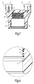
- the small groove 9 seen in Fig. 4 is that left by a flange formed on the mandrel for holding the wire coil in place during the moulding process.
- the cap By virtue of the screw thread the cap can be releasably yet securely attached to a saddle fitting. Thus, it can be secured to the fitting during storage and transit yet is easily detached, e.g. to enable insertion and subsequent withdrawal of the cutter. It may be re-applied to seal closed the end of the fitting tube for testing purposes, the seal 4 assisting the fluid tightness of the cap when it is screwed on to the fitting, and when ready the closure can be fixed permanently in place by welding the closure to the tube by connecting the contact pins 3 to a suitable source of electric current, the welded join then providing a reliable permanent seal.
- closure cap also includes an indicator to indicate that the closure cap has been welded in place.
- a circular groove 10 is formed in the side wall of the cap, the groove terminating near the heating coil and surrounding a peg 11 integral with the body. The pressure built up during the welding operation causes the peg 11 to be forced outwardly and to project from the cap, thereby to provide the required indication.
- a screw thread is not essential and other form of mechanical fastening may be used to secure the cap releasably to the fitting, such as a bayonet type fastening, although the fitting will need to be suitably adapted to receive the cap.
Abstract
Description
- This invention relates to pipe joints and in particular is concerned with so-called saddle fittings for making branch connections to a main pipe of thermoplastic material such as polyethylene.
- The known saddle fittings currently in use comprise a generally semi-cylindrical thermoplastic saddle portion with a concave surface of a curvature complementary to the external dimension of the main pipe to which it is to be fastened by welding. At a substantially central position the saddle portion includes a hole, and an integral tube which is connected to the saddle portion around the hole and projects essentially radially from the convex surface of the saddle portion. Connected to the tube intermediate its ends is a lateral spigot providing a connection for attachment of the branch pipe. For welding the saddle fitting to the main pipe it can be provided with a resistance heating coil located at the concave surface of the saddle portion and extending around the hole therein, and contacts for connecting the heating wire to a suitable source of electric current. The heat generated by the welding current flowing through the heating coil causes the thermoplastic material of the main pity and saddle portion, at their abutting surfaces, to melt so that upon subsequent cooling the main pipe and saddle portion are fused securely together. In order to open up communication with the interior of the main pipe a cutter is advanced along the tube of the saddle fitting so that its leading cutting edge passes through the hole in the saddle portion and severs a circular hole through the wall of the main pipe. Conveniently, the tube and the cutter are provided with complementary screw threads to facilitate the advancement and cutting action of the cutter by rotation of the cutter by means of an appropriate tool engaged therewith. When the hole has been cut through the main pipe the cutter is withdrawn and the outer end of the tube is closed off by a closure, such as a plug or cap adapted for sealing engagement with the free end of the tube. When the branch pipe has been correctly secured to the connection spigot the resultant pipe joint is ready for testing prior to use.
- The closures normally used for sealing the end of the saddle fitting tube are detachably mounted on the tube end, such as by a screw-threaded connection as shown in DE-U-8521528.7. This is advantageous since, for example, if a joint is found unsatisfactory during testing because the main pipe has not been cut through correctly, the closure can be removed and replaced again after repeating the cutting operation. On the other hand it means the closure can also be removed subsequent to satisfactory testing and should it not be re-applied correctly the pipe joint could leak, whereas no fault was indicated during testing.
- In GB-A-1408844 there is disclosed a closure in the form of a plug with a spring ring which engages an annular groove within the tube to lock the plug fixedly in place. This construction prevents removal of the plug after it has been inserted, but means the plug cannot be removed for checking purposes if tests on the joint give unsatisfactory results. Furthermore, it means the plug must be supplied detached from the fitting, which carries the inherent risk that it will be lost or mislaid in the field before the saddle jointing procedure is completed.
- The present invention provides a solution to these drawbacks and resides in a closure member for the cutter guide tube of a pipe saddle fitting, comprising means for secure but releasable engagement of the closure member with said tube, an electrical resistance heating wire incorporated in a thermoplastic portion of the member at a surface thereof arranged for contact with a surface of the tube, and electric contact means for supplying a electric current to the heating wire for fastening the closure permanently to the tube by welding.
- The closure member of the inventions retains all the benefits of a selectively detachable closure, but when a completed joint has been satisfactorily tested it can be permanently fixed in place so that the closure cannot be tampered with.
- The closure member may be a cap shaped to fit over the end of the tube, but could comprise a plug adapted to fit within an end portion of the tube. Conveniently the releasable engagement means comprises a screw thread. In the case of a closure plug it can be externally threaded for cooperation with the same screw thread as provided in the tube for advancing the cutter.
- The heating coil can be located closely adjacent the threaded surface of the closure since the threaded surfaces of the closure and tube will be in close cooperation and help to ensure a secure weld. However, in a preferred construction the heating coil is located at a cylindrical surface axially spaced from the screw thread for ease of manufacture.
- An embodiment of the invention is described below by way of example with reference to the accompanying drawings, in which:-
- Figure 1 is an axial section through a closure according to the invention;
- Figure 2 is a front elevation of the closure;
- Figure 3 is a aide elevation shown partially in section; and
- Figure 4 shows a detail of Figure 1 on an enlarged scale.
- The closure member depicted in the drawings comprises a cup
shaped body 1 of thermoplastic material. Integral with the body and located diametrically opposite each other are a pair ofsocket housings 2 accommodatingcentral contact pins 3 which have their lower ends embedded in the material of the body. The cavity defined within the cap is cylindrical and shaped for cooperation with the exterior of the cutter guide tube of an electro-fusion saddle fitting (not shown). It includes aninner section 5 with a screw thread for releasable cooperation with a complementary screw thread on the tube. The end wall of this threaded section has an annular groove in which an O ring seal 4 is accommodated. The cavity also includes a lower orouter section 6 with a generally smooth cylindrical surface and embedded in the material of the body closely adjacent this surface is an electricalresistance heating coil 8, the ends of which are respectively connected to thecontact pins 3. - In a manner known per se for production of electro-fusion sleeve fittings, a coil of coated wire can be wound onto a mandrel and the body injection moulded over the mandrel so that the wire becomes embedded into the material of the body. The small groove 9 seen in Fig. 4 is that left by a flange formed on the mandrel for holding the wire coil in place during the moulding process.
- By virtue of the screw thread the cap can be releasably yet securely attached to a saddle fitting. Thus, it can be secured to the fitting during storage and transit yet is easily detached, e.g. to enable insertion and subsequent withdrawal of the cutter. It may be re-applied to seal closed the end of the fitting tube for testing purposes, the seal 4 assisting the fluid tightness of the cap when it is screwed on to the fitting, and when ready the closure can be fixed permanently in place by welding the closure to the tube by connecting the
contact pins 3 to a suitable source of electric current, the welded join then providing a reliable permanent seal. - As shown the closure cap also includes an indicator to indicate that the closure cap has been welded in place. A
circular groove 10 is formed in the side wall of the cap, the groove terminating near the heating coil and surrounding a peg 11 integral with the body. The pressure built up during the welding operation causes the peg 11 to be forced outwardly and to project from the cap, thereby to provide the required indication. - A screw thread is not essential and other form of mechanical fastening may be used to secure the cap releasably to the fitting, such as a bayonet type fastening, although the fitting will need to be suitably adapted to receive the cap.
Claims (8)
- A closure member for the cutter guide tube of a pipe saddle fitting, comprising means for secure but releasable engagement of the closure member with said tube, characterised in that an electrical resistance heating wire (8) is incorporated in a thermoplastic portion of the member at a surface (6) thereof arranged for contact with the tube, and is connected to electric contact means (3) for supplying current to the heating wire for fastening the closure permanently to the tube by welding.
- A closure member according to claim 1, wherein the means for securing the member releasably to the tube comprises a screw thread.
- A closure member according to claim 1 or 2, wherein the heating wire is positioned at a substantially cylindrical surface (6) of the member.
- A closure according to claim 2 and claim 3, wherein said cylindrical surface (6) is spaced axially from the screw thread.
- A closure member according to claim 4, wherein the member is a cap with an internal cavity having an inner section (5) formed with the screw thread and an outer section (6) defining the cylindrical surface.
- A closure member according to any one of claims 1 to 5, wherein the member comprises a body (1) of thermoplastic material including an integral weld indicator (10, 11).
- A closure member according to any one of claims 1 to 6, wherein the contact means comprises a pair of contacts (3) housed within respective shrouds (2).
- A pipe saddle fitting having a cutter guide tube equipped with a closure member as defined in any one of claims 1 to 7 for sealing closed the free end of the tube.
Applications Claiming Priority (2)
| Application Number | Priority Date | Filing Date | Title |
|---|---|---|---|
| GB9101914 | 1991-01-29 | ||
| GB919101914A GB9101914D0 (en) | 1991-01-29 | 1991-01-29 | Pipe joints |
Publications (2)
| Publication Number | Publication Date |
|---|---|
| EP0497573A1 EP0497573A1 (en) | 1992-08-05 |
| EP0497573B1 true EP0497573B1 (en) | 1995-01-04 |
Family
ID=10689179
Family Applications (1)
| Application Number | Title | Priority Date | Filing Date |
|---|---|---|---|
| EP92300742A Expired - Lifetime EP0497573B1 (en) | 1991-01-29 | 1992-01-29 | Pipe closure device |
Country Status (10)
| Country | Link |
|---|---|
| US (1) | US5255942A (en) |
| EP (1) | EP0497573B1 (en) |
| AT (1) | ATE116726T1 (en) |
| AU (1) | AU641841B2 (en) |
| DE (2) | DE69201061T2 (en) |
| DK (1) | DK0497573T3 (en) |
| ES (1) | ES2069376T3 (en) |
| FR (1) | FR2672106B3 (en) |
| GB (2) | GB9101914D0 (en) |
| IT (1) | IT227453Y1 (en) |
Families Citing this family (17)
| Publication number | Priority date | Publication date | Assignee | Title |
|---|---|---|---|---|
| AU660669B2 (en) * | 1991-04-19 | 1995-07-06 | Sekisui Kagaku Kogyo Kabushiki Kaisha | Pipe connecting member |
| GB2282102B (en) * | 1993-09-06 | 1998-02-04 | Uponor Aldyl Ltd | Improvements in or relating to pipe fittings |
| DE4437249A1 (en) * | 1994-10-18 | 1996-04-25 | Freytag Ludwig Gmbh & Co Kg | Plastics pipeline pressure testing seal |
| US5835679A (en) | 1994-12-29 | 1998-11-10 | Energy Converters, Inc. | Polymeric immersion heating element with skeletal support and optional heat transfer fins |
| US6263158B1 (en) | 1999-05-11 | 2001-07-17 | Watlow Polymer Technologies | Fibrous supported polymer encapsulated electrical component |
| US6188051B1 (en) | 1999-06-01 | 2001-02-13 | Watlow Polymer Technologies | Method of manufacturing a sheathed electrical heater assembly |
| US6392208B1 (en) | 1999-08-06 | 2002-05-21 | Watlow Polymer Technologies | Electrofusing of thermoplastic heating elements and elements made thereby |
| US6433317B1 (en) | 2000-04-07 | 2002-08-13 | Watlow Polymer Technologies | Molded assembly with heating element captured therein |
| US6392206B1 (en) | 2000-04-07 | 2002-05-21 | Waltow Polymer Technologies | Modular heat exchanger |
| US6519835B1 (en) | 2000-08-18 | 2003-02-18 | Watlow Polymer Technologies | Method of formable thermoplastic laminate heated element assembly |
| US6539171B2 (en) | 2001-01-08 | 2003-03-25 | Watlow Polymer Technologies | Flexible spirally shaped heating element |
| US6524018B2 (en) * | 2001-03-01 | 2003-02-25 | Hon Hai Precision Ind. Co., Ltd. | Optical assembly |
| GB2516301B (en) | 2013-07-18 | 2016-06-08 | Pioneer Lining Tech Ltd | Improved electrofusion fitting methods |
| FR3030676A1 (en) * | 2014-12-23 | 2016-06-24 | Vallourec Oil & Gas France | DEVICE FOR PROTECTING AN END OF A FLEXIBLE TUBULAR THREADED JOINT COMPONENT |
| USD757232S1 (en) | 2015-02-12 | 2016-05-24 | Electrolux Home Products, Inc. | Plug for an auxiliary inlet of a garbage disposal |
| CN105587960A (en) * | 2015-06-18 | 2016-05-18 | 崔文亮 | Hot-melting connection assembly and connecting method thereof |
| DE102017126250A1 (en) * | 2017-11-09 | 2019-05-09 | Westnetz Gmbh | Fitting system for introducing a glass fiber transport line into a gas line, system with such a fitting system and method for laying a fiber optic transport line |
Family Cites Families (15)
| Publication number | Priority date | Publication date | Assignee | Title |
|---|---|---|---|---|
| US2495615A (en) * | 1944-04-17 | 1950-01-24 | Round Root Corp | Welded coupling |
| US2736335A (en) * | 1953-03-23 | 1956-02-28 | Claude H Webber | Tapping and cutoff connection to plastic fluid pressure main |
| US3583458A (en) * | 1969-05-26 | 1971-06-08 | Allan A Costa | Miniature plastic containers |
| US3784235A (en) * | 1971-10-08 | 1974-01-08 | Us Navy | Tubular adhesive joint with snap lock |
| CH528697A (en) * | 1972-02-08 | 1972-09-30 | Rollmaplast Ag Kunststoffrohr | Electrically weldable tapping fitting made of thermoplastic material |
| US4059291A (en) * | 1974-09-13 | 1977-11-22 | Polva Nederland B. V. | Branch connection |
| US4018246A (en) * | 1975-06-02 | 1977-04-19 | Watsco, Inc. | Line tap valve |
| GB1544441A (en) * | 1976-02-18 | 1979-04-19 | Polva Nederland Bv | Method of and device for manufacturing a component of synthetic material and a resistance element |
| FR2519578A1 (en) * | 1981-07-01 | 1983-07-18 | Sam Innovation Tech | PLASTIC DEVICE FOR REALIZING PERFORATION IN A PLASTIC UNDERLYING ELEMENT, METHOD OF MANUFACTURING SUCH A DEVICE AND ITS IMPLEMENTATION FOR PERFORMING PIPELINE DERIVATIONS |
| US4622087A (en) * | 1983-02-18 | 1986-11-11 | The Victaulic Company Plc | Method of making weldable pipe fittings |
| MC1581A1 (en) * | 1983-12-02 | 1985-02-04 | Toutelectric | METHOD FOR CONTROLLING THE WELDING TIME |
| US4708374A (en) * | 1984-07-30 | 1987-11-24 | Naco Industries, Inc. | Plastic Tee fitting |
| ATE32132T1 (en) * | 1984-08-08 | 1988-02-15 | Fischer Ag Georg | DRILLING PIECE MADE OF WELDABLE PLASTIC. |
| US5150922A (en) * | 1989-01-11 | 1992-09-29 | Osaka Gas Co., Ltd. | Electrofusion joint and hot water supply header using the same |
| DE3928843A1 (en) * | 1989-08-31 | 1991-03-14 | Friedrichsfeld Gmbh | Block for fitment for attachment to pipe - consists of stopper, sealing-ring, socket and internally threaded insert |
-
1991
- 1991-01-29 GB GB919101914A patent/GB9101914D0/en active Pending
-
1992
- 1992-01-23 US US07/824,533 patent/US5255942A/en not_active Expired - Fee Related
- 1992-01-28 AU AU10517/92A patent/AU641841B2/en not_active Ceased
- 1992-01-28 IT IT92TO000016U patent/IT227453Y1/en active IP Right Grant
- 1992-01-29 DE DE69201061T patent/DE69201061T2/en not_active Expired - Fee Related
- 1992-01-29 DE DE9201048U patent/DE9201048U1/de not_active Expired - Lifetime
- 1992-01-29 DK DK92300742.1T patent/DK0497573T3/en active
- 1992-01-29 FR FR929200963A patent/FR2672106B3/en not_active Expired - Fee Related
- 1992-01-29 GB GB9201924A patent/GB2252384B/en not_active Expired - Fee Related
- 1992-01-29 AT AT92300742T patent/ATE116726T1/en not_active IP Right Cessation
- 1992-01-29 ES ES92300742T patent/ES2069376T3/en not_active Expired - Lifetime
- 1992-01-29 EP EP92300742A patent/EP0497573B1/en not_active Expired - Lifetime
Also Published As
| Publication number | Publication date |
|---|---|
| ES2069376T3 (en) | 1995-05-01 |
| ITTO920016V0 (en) | 1992-01-28 |
| FR2672106A3 (en) | 1992-07-31 |
| DE69201061D1 (en) | 1995-02-16 |
| ITTO920016U1 (en) | 1993-07-28 |
| GB9201924D0 (en) | 1992-03-18 |
| AU1051792A (en) | 1992-08-06 |
| GB2252384B (en) | 1994-06-01 |
| ATE116726T1 (en) | 1995-01-15 |
| EP0497573A1 (en) | 1992-08-05 |
| DK0497573T3 (en) | 1995-03-13 |
| GB9101914D0 (en) | 1991-03-13 |
| DE69201061T2 (en) | 1995-05-11 |
| US5255942A (en) | 1993-10-26 |
| GB2252384A (en) | 1992-08-05 |
| AU641841B2 (en) | 1993-09-30 |
| FR2672106B3 (en) | 1993-01-15 |
| IT227453Y1 (en) | 1997-12-15 |
| DE9201048U1 (en) | 1992-07-23 |
Similar Documents
| Publication | Publication Date | Title |
|---|---|---|
| EP0497573B1 (en) | Pipe closure device | |
| US4176274A (en) | Method of coupling plastic pipes by welding and a connection piece for coupling same | |
| CA1260663A (en) | Electrofusion coupler | |
| JPH08247373A (en) | Socket member and pipe connecting member | |
| US4958857A (en) | Welding seal assembly | |
| PL182820B1 (en) | Leak-tight union piece | |
| EP2178691B1 (en) | Electrofusion fitting | |
| EP0594361B1 (en) | Branch pipe connection | |
| US6521072B1 (en) | Method of coupling profile wall thermoplastic pipes | |
| US6198081B1 (en) | Welding sleeve of thermoplastic material with indicator | |
| JP2011117563A (en) | Electric fusion joint | |
| KR100227402B1 (en) | Connecting element for a pipe lining and method of producing same | |
| JPH05196188A (en) | Closing device and pipe saddle fixture | |
| US3270114A (en) | Method of molding material to one end of a preformed thermoplastic tube | |
| JP2000055281A (en) | Electric fusing coupler and its protective cap | |
| JPH08270873A (en) | Electric fusion joint | |
| JP2005163960A (en) | Cap with purge port | |
| JPH09242970A (en) | Electrically fused joint | |
| JPH0979470A (en) | Electric fusion branch pipe coupling | |
| JPH08135875A (en) | Electro-fusion coupling | |
| JP2676494B2 (en) | Electrofusion joint joint fitting retaining method | |
| JPH06207698A (en) | Pipe line blocking cap | |
| JPH0147677B2 (en) | ||
| JP2000179777A (en) | Snap tap with fused saddle | |
| JPS5715923A (en) | Testing method for welding of socket |
Legal Events
| Date | Code | Title | Description |
|---|---|---|---|
| PUAI | Public reference made under article 153(3) epc to a published international application that has entered the european phase |
Free format text: ORIGINAL CODE: 0009012 |
|
| AK | Designated contracting states |
Kind code of ref document: A1 Designated state(s): AT BE DE DK ES FR GB IT NL PT SE |
|
| 17P | Request for examination filed |
Effective date: 19930119 |
|
| 17Q | First examination report despatched |
Effective date: 19940301 |
|
| RBV | Designated contracting states (corrected) |
Designated state(s): AT BE DE DK ES FR IT NL PT SE |
|
| GRAA | (expected) grant |
Free format text: ORIGINAL CODE: 0009210 |
|
| AK | Designated contracting states |
Kind code of ref document: B1 Designated state(s): AT BE DE DK ES FR IT NL PT SE |
|
| PG25 | Lapsed in a contracting state [announced via postgrant information from national office to epo] |
Ref country code: BE Effective date: 19950104 Ref country code: AT Effective date: 19950104 |
|
| REF | Corresponds to: |
Ref document number: 116726 Country of ref document: AT Date of ref document: 19950115 Kind code of ref document: T |
|
| ITF | It: translation for a ep patent filed |
Owner name: JACOBACCI & PERANI S.P.A. |
|
| PGFP | Annual fee paid to national office [announced via postgrant information from national office to epo] |
Ref country code: DE Payment date: 19950121 Year of fee payment: 4 |
|
| PGFP | Annual fee paid to national office [announced via postgrant information from national office to epo] |
Ref country code: FR Payment date: 19950124 Year of fee payment: 4 |
|
| PGFP | Annual fee paid to national office [announced via postgrant information from national office to epo] |
Ref country code: DK Payment date: 19950125 Year of fee payment: 4 |
|
| PGFP | Annual fee paid to national office [announced via postgrant information from national office to epo] |
Ref country code: NL Payment date: 19950131 Year of fee payment: 4 Ref country code: ES Payment date: 19950131 Year of fee payment: 4 |
|
| REF | Corresponds to: |
Ref document number: 69201061 Country of ref document: DE Date of ref document: 19950216 |
|
| REG | Reference to a national code |
Ref country code: DK Ref legal event code: T3 |
|
| ET | Fr: translation filed | ||
| PG25 | Lapsed in a contracting state [announced via postgrant information from national office to epo] |
Ref country code: SE Effective date: 19950404 Ref country code: PT Effective date: 19950404 |
|
| REG | Reference to a national code |
Ref country code: ES Ref legal event code: FG2A Ref document number: 2069376 Country of ref document: ES Kind code of ref document: T3 |
|
| PLBE | No opposition filed within time limit |
Free format text: ORIGINAL CODE: 0009261 |
|
| STAA | Information on the status of an ep patent application or granted ep patent |
Free format text: STATUS: NO OPPOSITION FILED WITHIN TIME LIMIT |
|
| 26N | No opposition filed | ||
| PG25 | Lapsed in a contracting state [announced via postgrant information from national office to epo] |
Ref country code: DK Effective date: 19960129 |
|
| REG | Reference to a national code |
Ref country code: DK Ref legal event code: EBP |
|
| PG25 | Lapsed in a contracting state [announced via postgrant information from national office to epo] |
Ref country code: ES Free format text: LAPSE BECAUSE OF NON-PAYMENT OF DUE FEES Effective date: 19960130 |
|
| PG25 | Lapsed in a contracting state [announced via postgrant information from national office to epo] |
Ref country code: NL Effective date: 19960801 |
|
| PG25 | Lapsed in a contracting state [announced via postgrant information from national office to epo] |
Ref country code: FR Effective date: 19960930 |
|
| NLV4 | Nl: lapsed or anulled due to non-payment of the annual fee |
Effective date: 19960801 |
|
| PG25 | Lapsed in a contracting state [announced via postgrant information from national office to epo] |
Ref country code: DE Effective date: 19961001 |
|
| REG | Reference to a national code |
Ref country code: FR Ref legal event code: ST |
|
| REG | Reference to a national code |
Ref country code: ES Ref legal event code: FD2A Effective date: 19990301 |
|
| PG25 | Lapsed in a contracting state [announced via postgrant information from national office to epo] |
Ref country code: IT Free format text: LAPSE BECAUSE OF NON-PAYMENT OF DUE FEES;WARNING: LAPSES OF ITALIAN PATENTS WITH EFFECTIVE DATE BEFORE 2007 MAY HAVE OCCURRED AT ANY TIME BEFORE 2007. THE CORRECT EFFECTIVE DATE MAY BE DIFFERENT FROM THE ONE RECORDED. Effective date: 20050129 |