EP0498674A2 - Moving picture image encoder - Google Patents
Moving picture image encoder Download PDFInfo
- Publication number
- EP0498674A2 EP0498674A2 EP92301064A EP92301064A EP0498674A2 EP 0498674 A2 EP0498674 A2 EP 0498674A2 EP 92301064 A EP92301064 A EP 92301064A EP 92301064 A EP92301064 A EP 92301064A EP 0498674 A2 EP0498674 A2 EP 0498674A2
- Authority
- EP
- European Patent Office
- Prior art keywords
- step size
- quantization step
- unit time
- data
- preset value
- Prior art date
- Legal status (The legal status is an assumption and is not a legal conclusion. Google has not performed a legal analysis and makes no representation as to the accuracy of the status listed.)
- Ceased
Links
Images


Classifications
-
- H—ELECTRICITY
- H04—ELECTRIC COMMUNICATION TECHNIQUE
- H04N—PICTORIAL COMMUNICATION, e.g. TELEVISION
- H04N19/00—Methods or arrangements for coding, decoding, compressing or decompressing digital video signals
- H04N19/10—Methods or arrangements for coding, decoding, compressing or decompressing digital video signals using adaptive coding
- H04N19/134—Methods or arrangements for coding, decoding, compressing or decompressing digital video signals using adaptive coding characterised by the element, parameter or criterion affecting or controlling the adaptive coding
- H04N19/146—Data rate or code amount at the encoder output
- H04N19/152—Data rate or code amount at the encoder output by measuring the fullness of the transmission buffer
-
- H—ELECTRICITY
- H04—ELECTRIC COMMUNICATION TECHNIQUE
- H04N—PICTORIAL COMMUNICATION, e.g. TELEVISION
- H04N19/00—Methods or arrangements for coding, decoding, compressing or decompressing digital video signals
- H04N19/10—Methods or arrangements for coding, decoding, compressing or decompressing digital video signals using adaptive coding
- H04N19/102—Methods or arrangements for coding, decoding, compressing or decompressing digital video signals using adaptive coding characterised by the element, parameter or selection affected or controlled by the adaptive coding
- H04N19/124—Quantisation
- H04N19/126—Details of normalisation or weighting functions, e.g. normalisation matrices or variable uniform quantisers
-
- H—ELECTRICITY
- H04—ELECTRIC COMMUNICATION TECHNIQUE
- H04N—PICTORIAL COMMUNICATION, e.g. TELEVISION
- H04N19/00—Methods or arrangements for coding, decoding, compressing or decompressing digital video signals
- H04N19/10—Methods or arrangements for coding, decoding, compressing or decompressing digital video signals using adaptive coding
- H04N19/169—Methods or arrangements for coding, decoding, compressing or decompressing digital video signals using adaptive coding characterised by the coding unit, i.e. the structural portion or semantic portion of the video signal being the object or the subject of the adaptive coding
- H04N19/17—Methods or arrangements for coding, decoding, compressing or decompressing digital video signals using adaptive coding characterised by the coding unit, i.e. the structural portion or semantic portion of the video signal being the object or the subject of the adaptive coding the unit being an image region, e.g. an object
- H04N19/172—Methods or arrangements for coding, decoding, compressing or decompressing digital video signals using adaptive coding characterised by the coding unit, i.e. the structural portion or semantic portion of the video signal being the object or the subject of the adaptive coding the unit being an image region, e.g. an object the region being a picture, frame or field
-
- H—ELECTRICITY
- H04—ELECTRIC COMMUNICATION TECHNIQUE
- H04N—PICTORIAL COMMUNICATION, e.g. TELEVISION
- H04N19/00—Methods or arrangements for coding, decoding, compressing or decompressing digital video signals
- H04N19/10—Methods or arrangements for coding, decoding, compressing or decompressing digital video signals using adaptive coding
- H04N19/169—Methods or arrangements for coding, decoding, compressing or decompressing digital video signals using adaptive coding characterised by the coding unit, i.e. the structural portion or semantic portion of the video signal being the object or the subject of the adaptive coding
- H04N19/17—Methods or arrangements for coding, decoding, compressing or decompressing digital video signals using adaptive coding characterised by the coding unit, i.e. the structural portion or semantic portion of the video signal being the object or the subject of the adaptive coding the unit being an image region, e.g. an object
- H04N19/176—Methods or arrangements for coding, decoding, compressing or decompressing digital video signals using adaptive coding characterised by the coding unit, i.e. the structural portion or semantic portion of the video signal being the object or the subject of the adaptive coding the unit being an image region, e.g. an object the region being a block, e.g. a macroblock
-
- H—ELECTRICITY
- H04—ELECTRIC COMMUNICATION TECHNIQUE
- H04N—PICTORIAL COMMUNICATION, e.g. TELEVISION
- H04N19/00—Methods or arrangements for coding, decoding, compressing or decompressing digital video signals
- H04N19/10—Methods or arrangements for coding, decoding, compressing or decompressing digital video signals using adaptive coding
- H04N19/189—Methods or arrangements for coding, decoding, compressing or decompressing digital video signals using adaptive coding characterised by the adaptation method, adaptation tool or adaptation type used for the adaptive coding
- H04N19/196—Methods or arrangements for coding, decoding, compressing or decompressing digital video signals using adaptive coding characterised by the adaptation method, adaptation tool or adaptation type used for the adaptive coding being specially adapted for the computation of encoding parameters, e.g. by averaging previously computed encoding parameters
-
- H—ELECTRICITY
- H04—ELECTRIC COMMUNICATION TECHNIQUE
- H04N—PICTORIAL COMMUNICATION, e.g. TELEVISION
- H04N19/00—Methods or arrangements for coding, decoding, compressing or decompressing digital video signals
- H04N19/60—Methods or arrangements for coding, decoding, compressing or decompressing digital video signals using transform coding
- H04N19/61—Methods or arrangements for coding, decoding, compressing or decompressing digital video signals using transform coding in combination with predictive coding
-
- H—ELECTRICITY
- H04—ELECTRIC COMMUNICATION TECHNIQUE
- H04N—PICTORIAL COMMUNICATION, e.g. TELEVISION
- H04N19/00—Methods or arrangements for coding, decoding, compressing or decompressing digital video signals
- H04N19/10—Methods or arrangements for coding, decoding, compressing or decompressing digital video signals using adaptive coding
- H04N19/134—Methods or arrangements for coding, decoding, compressing or decompressing digital video signals using adaptive coding characterised by the element, parameter or criterion affecting or controlling the adaptive coding
- H04N19/146—Data rate or code amount at the encoder output
Definitions
- the present invention relates to a moving picture image encoding device which encodes a moving picture image signal for transmission at a fixed transmission rate.
- a moving picture image encoding device is disclosed in, for instance, USP No. 4,951,140.
- an interframe difference signal between image signals of one-frame before and after, which are input on a frame-by-frame basis, is produced and then subjected to discrete cosine transform in a DCT (discrete cosine transform) circuit.
- DCT coefficient data output from the DCT circuit is quantized by a quantization circuit and then coded by a variable-length coding circuit. Codes output from the variable-length coding circuit are temporarily stored in a buffer memory. The contents of the buffer memory are read at a fixed transmission rate and sent to a transmission line.
- the quantization step size of the quantization circuit is controlled according to the quantity of codes stored in the buffer memory so that the buffer memory will not overflow. That is, when the buffer content of the buffer memory is not less than a preset value, the quantization step size is made large, thereby decreasing the quantity of codes generated from the variable-length coding circuit. When the buffer content is less than the preset value, the quantization step size is made small, thereby increasing the quantity of codes from the coding circuit. The occurrence of underflow of the buffer memory can be prevented by storing dummy data in the buffer memory.
- the quantization step size of the quantization circuit is feedback-controlled so that the buffer content may fall below a predetermined value.
- the feedback control may cause an oscillatory phenomenon in which the quantization step size varies at short intervals. In case where the oscillatory phenomenon occurs, the quality of a picture reproduced at the decoding side will vary with time. That is, the picture quality deteriorates.
- an input image signal is coded by a first coding circuit and then quantized in accordance with a variable quantization step size by a quantization circuit.
- An output signal of the quantization circuit is variable-length coded by a second coding circuit and the resultant codes are temporarily stored in a buffer memory.
- the quantization step size is controlled by a quantization control circuit according to the quantity of codes stored in the buffer memory.
- the quantization control circuit decrements the quantization step size by a first unit quantity every a first unit time or increments the quantization step size by a second unit quantity every a second unit time shorter than the first unit time when a parameter value related to the quantity of codes stored in the buffer memory is not less than a preset value.
- the quantization step size is decremented every the first unit time in the steady state.
- the quantization step size is incremented every the second unit time shorter than the first unit time.
- the first unit time is selected to be a relatively long period, for example, one frame period of the input image signal, the variation of the quantization step size in the steady state is reduced. Thereby, the variation of the quality of a reproduced picture is also reduced.
- the quantization step size can be incremented immediately when the parameter value becomes equal to or larger than the preset value and thus the quantity of codes generated is decreased rapidly. Thereby, the buffer content can be kept within the preset value, preventing the buffer memory from overflowing.
- a moving picture image encoding device embodying the present invention comprises an A/D converter (analog to digital converter) 2, a subtracter 3, a DCT (discrete cosine transform) circuit 4, a quantization circuit 5, an inverse quantization circuit 6, an inverse DCT circuit 7, an adder 8, a frame memory 9, a variable-length coding circuit 10, a buffer memory 11 and a quantization control circuit 13.
- the quantization control circuit 13 is a circuit which is adapted to generate quantization step size data 14 in order to control the quantization step size of the quantization circuit 5 according to the buffer content of the buffer memory 11. That is, as described later, the quantization control circuit performs non-linear feed-back control to vary an interval of time (period) at which the quantization step size is varied according to whether or not the buffer content is not less than a preset value.
- a moving picture image signal is applied to an input terminal 1 in frame units.
- the image signal is first converted to a digital signal by the A/D converter 2.
- the subtracter 3 produces an interframe difference signal by subtraction of a digital image signal corresponding to each frame and an image signal of one-frame before stored in the frame memory 9.
- the interframe difference signal is subjected to discrete cosine transform in blocks of, for example, 8 ⁇ 8 pixels by the DCT circuit 4.
- the discrete cosine transform is also called the DCT coding and used to eliminate correlation between pixels.
- the DCT circuit 4 outputs DCT coefficient data as coded data.
- the DCT coefficient data is quantized by the quantization circuit 5.
- the quantized data is variable-length coded by the variable length coder 10. Codes output from the variable length coder are temporarily stored in the buffer memory 11.
- the codes stored in the buffer memory 11 are read at a fixed transmission rate for transmission to a transmission line not shown.
- the quantized signal from the quantization circuit 5 is also applied to the inverse quantization circuit 6 which performs the inverse of the operation of the quantization circuit 5, i.e., the inverse quantization.
- a quantization step size data 14 is applied from the quantization control circuit 13 to the inverse quantization circuit 6.
- An output signal of the inverse quantization circuit 6 is subjected to the inverse discrete cosine transform in the IDCT circuit 7.
- the adder 8 adds an output signal of the IDCT circuit 7 and an image signal of one-frame before from the frame memory 9, thereby outputting a local decoded signal.
- the local decoded signal is stored in the frame memory 9 and used to obtain an interframe difference signal with an image signal corresponding to the next frame.
- the quantization control circuit 13 controls the quantization step size of the quantization circuit 5 by means of the non-linear feedback control. To be specific, the quantization control circuit 13 decrements the quantization step size by a first unit quantity every a first unit time.
- the quantization control circuit 13 compares the buffer content of the buffer memory 11 with a suitable preset value and, when the buffer content is equal to or larger than the preset value, increments the quantization step size by a second unit quantity every a second unit time which is shorter than the first unit time.
- the first unit time is selected to be, for example, the time for one frame of image signals (the frame period).
- the second unit time is selected to be, for example, the time for one block of image signals (the block period).
- the quantization step size is decremented slowly at a speed corresponding to the frame period in the steady state where the buffer content is less than the preset value, so that the step size does not vary greatly. This prevents variations of the reproduced picture quality at the decoding side.
- the quantity of codes output from the variable length coding circuit 10 increases. From this it follows that the buffer content increases and reaches the preset value. Then, the quantization step size will be made large in a short time at a speed corresponding to the block period. Thereby, the quantity of codes output from the variable length coding circuit 10 is reduced rapidly, so that the buffer memory 11 is prevented from overflowing.
- the buffer memory 11 can be prevented from underflowing by storing dummy data in it.
- Fig. 2 shows an arrangement of the quantization control circuit 13.
- the quantization control circuit comprises a comparator 21, an AND gate 22 and an up-down counter 23.
- the comparator makes a comparison between the buffer content (BC) of the buffer memory 11 of Fig. 1 and the preset value (PV).
- the AND gate 22 is responsive to the output of the comparator to control the passage of clock pulses CK with the block period.
- the up-down counter 23 has a terminal D connected to receive frame pulses (FP) with the frame period and a terminal U connected to receive the clock pulses CK with the block period from the AND gate 22.
- the up-down counter 23 is responsive to each pulse at the terminal D to count down and to each pulse at the terminal U to count up.
- the quantization step size data 14 is output from an output terminal Q of the up-down counter 23 to the quantization circuit 5 of Fig. 1, thereby controlling the quantization step size of the quantization circuit 5.
- the up-down counter 23 in the steady state where the buffer content BC of the buffer memory 11 is less than the preset value PV, is responsive to the frame pulse FP to count down with each frame, so that its output, i.e., the quantization step size data 14 is decremented by the first unit quantity with each frame.
- the output of the comparator 21 goes high, allowing the clock pulses CK with the block period to pass through the AND gate 22.
- the up-down counter 23 counts up with each of the clock pulses CK and its output, i.e., the quantization step size data 14 is incremented by the second unit quantity with each block.
- the first and second unit quantities are determined by the number of bits of the up-down counter 23. In this case, the first and second unit quantities are made equal to each other.
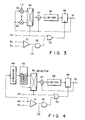
- Fig. 3 shows another arrangement of the quantization control circuit 13, which comprises a comparator 31, an AND gate 32, an OR gate 33, multipliers 34 and 35, a selector 36, an adder 37, a limiter 38 and a register 39.
- the comparator 31 and the AND gate 32 operate in the same manner as the comparator 21 and the AND gate 22, respectively, of Fig. 2.
- the variations (increment and decrement) of the quantization step size can be changed according to the current quantization step size (before variation).
- the multipliers 34 and 35 multiply the current quantization step size 14 by coefficients "-a" and "b", respectively.
- the coefficients "a” and "b” each indicate a positive constant.
- the selector 36 selects the output of the multiplier 34. Otherwise, it selects the output of the multiplier 35.
- the output of the selector 36 is added to the current quantization step size data 14 in the adder 37.
- the output value of the adder 37 is limited by the limiter 38 so that it will not exceed the upper or lower limit value of the quantization step size.
- the output of the limiter 38 is applied to the register 39.
- a value is held in the register 39 which corresponds to the sum of the output of the multiplier 34 and the current quantization step size data, output from the adder 37, and is limited by the limiter 38.
- the value held in the register 39 is output as the quantization step size data 14.
- the quantization step size is incremented by a quantity corresponding to the product of the preceding quantization step size and the coefficient "a".
- the content of the register 39 is replaced with a value which corresponds to the sum of the output of the multiplier 35 and the preceding quantization step size data, output from the adder 37, and is limited by the limiter 38.
- the quantization step size is incremented by a quantity corresponding to the product of the preceding quantization step size and the coefficient "b".
- the decrement value of the quantization step size with each frame when the buffer content is less than the preset value PV corresponds to a value obtained by multiplying the preceding quantization step size by the coefficient "a".
- the larger the current quantization step size the larger this value becomes.
- the increment value of the quantization step size with each block when the buffer content BC is equal to or more than the preset value PV corresponds to a value obtained by multiplying the preceding quantization step size by the coefficient "b". In this case as well, the larger the current quantization step size, the larger this value becomes.
- the quantization step size when, for example, an object in the image stops moving, the quantization step size will become small enough in a short time corresponding to several frame periods, permitting a picture with good definition to be obtained rapidly. Moreover, when the quantization step size becomes small, its variation can be suppressed well and the deterioration of recording picture quality due to the variation of the picture quality can be suppressed. Furthermore, when the object in the image begins moving or moves actively, the quantization step size will become larger in a short time, thus surely preventing the buffer memory 11 from overflowing.
- Fig. 4 illustrates still another arrangement of the quantization control circuit.
- This quantization control circuit is arranged to greatly decrement the quantization step size when the preceding frame is a still picture and comprises a comparator 41, an AND gate 42, an OR gate 43, an averaging circuit 44, an inversenumber circuit 45, a selector 46, an adder 47, a limiter 48 and a register 49.
- the comparator 41, the AND gate 42, the OR gate 43, the adder 47, the limiter 48 and the register 49 are the same as corresponding ones shown in Fig. 3.
- the averaging circuit 44 calculates the time-average value of the buffer content BC, and the inversenumber circuit 45 obtains the reciprocal of the time-average value of the buffer content.
- the selector 46 is responsive to application of the frame pulse FP thereto to select the output of the inverse-number circuit 46. When no frame pulse is applied, the selector 46 selects a "1". As in the case of Fig. 3, the output of the selector 46 is added to the preceding quantization step size 14 in the adder 47, and the output of the adder is limited by the limiter 48 so that it will not exceed the upper and lower limit values of the quantization step size and then entered into the register 49.
- the register 49 holds a value obtained by limiting the sum of the reciprocal of the one-frame average of the buffer content BC and the preceding quantization step size data.
- the value held in the register 49 is output as the quantization step size data 14.
- the comparator 41 allows the clocks CK with the block period to pass through the AND gate 42 and enter the register 49 via the OR gate 43. Thereby, the content of the register 49 is replaced with a value obtained by adding a 1 to the preceding quantization step size in the adder 47 and limiting the sum in the limiter 48, and the quantization step size is incremented by one.
- the quantization control circuit 13 is implemented with specific hardware, it is also possible to implement the same processing as is performed by the circuits of Figs. 2 through 4 with software by using a microprocessor for the quantization control circuit.
- Fig. 5 there is illustrated a flowchart for an algorithm for implementing the function of the circuit of Fig. 3 with software.
- step S3 a check is made, for each block, as to whether or not the buffer content BC is less than the preset value PV (step S3).
- the time interval (the first unit time) at which the quantization step size is decremented is not necessarily required to be one frame period. It may be, for example, half of one frame period or several frame periods. Also, the time interval (the second unit time) at which the quantization step size is incremented is not required to be one block period and may be, for example, several block periods.
- Fig. 6 illustrates a further arrangement of the quantization control circuit 13.
- a preset value generator 24 for generating a variable preset value PV is added to the quantization control circuit shown in Fig. 2.
- the preset value generator 24 is controlled by the quantization step size data 14, so that the preset value PV to be generated varies with the quantization step size. That is, the preset value PV is made large in the steady state where the quantization step size is relatively small, thus making it difficult for the quantization step size to become large even if the buffer content is increased. Conversely, when the quantization step size is relatively large, the preset value PV is made large, thus making it easy for the quantization step size to become large. Therefore, the quantization control circuit of Fig. 6 can enhance the effects of prevention of variations of picture quality due to suppression of variations of the quantization step size in the steady state and prevention of overflow of the buffer memory 11 when the buffer content BC exceeds the preset value PV.
- Fig. 7 illustrates a still further arrangement of the quantization control circuit 13.
- a clock generator 25 is provided which generates clocks CK with a variable period.
- the clock generator 25 is controlled by the quantization step size data 14 in such a way that the smaller the quantization step size, the period of the clocks CK becomes longer.
- This arrangement permits variations of the quantization step size in the steady state where it is small to be suppressed more effectively, thereby preventing variations of picture quality.
- a comparison is made between the buffer content BC and the preset value PV
- use may be made of any other parameter if it is related to the buffer content BC.
- Such parameters include, for example, (a) the residual capacity of the buffer memory 11, (b) the quantity of increase of the buffer content BC, (c) the quantity of codes generated within a block or a fixed time, (d) a parameter of a image signal prior to coding (for example, the variance of an input image signal), etc.
Abstract
Description
- The present invention relates to a moving picture image encoding device which encodes a moving picture image signal for transmission at a fixed transmission rate.
- Progress is being made in the development of videophone and teleconferencing with a background of the preparation of digital communications networks and the advance of digital communications technologies. One of the most important technologies of realizing the videophone and the teleconferencing is moving picture image encoding.
- A moving picture image encoding device is disclosed in, for instance, USP No. 4,951,140. In this moving picture image encoding device, an interframe difference signal between image signals of one-frame before and after, which are input on a frame-by-frame basis, is produced and then subjected to discrete cosine transform in a DCT (discrete cosine transform) circuit. DCT coefficient data output from the DCT circuit is quantized by a quantization circuit and then coded by a variable-length coding circuit. Codes output from the variable-length coding circuit are temporarily stored in a buffer memory. The contents of the buffer memory are read at a fixed transmission rate and sent to a transmission line.
- The quantization step size of the quantization circuit is controlled according to the quantity of codes stored in the buffer memory so that the buffer memory will not overflow. That is, when the buffer content of the buffer memory is not less than a preset value, the quantization step size is made large, thereby decreasing the quantity of codes generated from the variable-length coding circuit. When the buffer content is less than the preset value, the quantization step size is made small, thereby increasing the quantity of codes from the coding circuit. The occurrence of underflow of the buffer memory can be prevented by storing dummy data in the buffer memory.
- In this way, the quantization step size of the quantization circuit is feedback-controlled so that the buffer content may fall below a predetermined value. The feedback control may cause an oscillatory phenomenon in which the quantization step size varies at short intervals. In case where the oscillatory phenomenon occurs, the quality of a picture reproduced at the decoding side will vary with time. That is, the picture quality deteriorates.
- It is an object of the present invention to provide a moving picture image encoding device which permits the buffer content to fall below a preset value without causing a great variation of the quality of a picture reproduced by a decoder.
- According to the present invention, an input image signal is coded by a first coding circuit and then quantized in accordance with a variable quantization step size by a quantization circuit. An output signal of the quantization circuit is variable-length coded by a second coding circuit and the resultant codes are temporarily stored in a buffer memory. The quantization step size is controlled by a quantization control circuit according to the quantity of codes stored in the buffer memory. The quantization control circuit decrements the quantization step size by a first unit quantity every a first unit time or increments the quantization step size by a second unit quantity every a second unit time shorter than the first unit time when a parameter value related to the quantity of codes stored in the buffer memory is not less than a preset value.
- In the present invention, the quantization step size is decremented every the first unit time in the steady state. When the parameter value related to the buffer content becomes equal to or more than the preset value, the quantization step size is incremented every the second unit time shorter than the first unit time. In this case, if the first unit time is selected to be a relatively long period, for example, one frame period of the input image signal, the variation of the quantization step size in the steady state is reduced. Thereby, the variation of the quality of a reproduced picture is also reduced. If the second unit time is selected to be a relatively short period, for example, one block period, on the other hand, the quantization step size can be incremented immediately when the parameter value becomes equal to or larger than the preset value and thus the quantity of codes generated is decreased rapidly. Thereby, the buffer content can be kept within the preset value, preventing the buffer memory from overflowing.
- This invention can be more fully understood from the following detailed description when taken in conjunction with the accompanying drawings, in which:
- Fig. 1 is a block diagram of a moving picture image encoding device according to an embodiment of the present invention;
- Fig. 2 is a block diagram illustrating an arrangement of the quantization control circuit of Fig. 1;
- Fig. 3 is a block diagram illustrating another arrangement of the quantization control circuit of Fig. 1;
- Fig. 4 is a block diagram illustrating still another arrangement of the quantization control circuit of Fig. 1;
- Fig. 5 is a flowchart for an algorithm for implementing the quantization control circuit of Fig. 1 with software;
- Fig. 6 is a block diagram illustrating a further arrangement of the quantization control circuit of Fig. 1; and
- Fig. 7 is a block diagram illustrating a still further arrangement of the quantization control circuit of Fig. 1.
- Referring now to Fig. 1, a moving picture image encoding device embodying the present invention comprises an A/D converter (analog to digital converter) 2, a
subtracter 3, a DCT (discrete cosine transform) circuit 4, aquantization circuit 5, aninverse quantization circuit 6, aninverse DCT circuit 7, anadder 8, a frame memory 9, a variable-length coding circuit 10, abuffer memory 11 and aquantization control circuit 13. Thequantization control circuit 13 is a circuit which is adapted to generate quantizationstep size data 14 in order to control the quantization step size of thequantization circuit 5 according to the buffer content of thebuffer memory 11. That is, as described later, the quantization control circuit performs non-linear feed-back control to vary an interval of time (period) at which the quantization step size is varied according to whether or not the buffer content is not less than a preset value. - Next, the operation of the moving picture image encoding device of the present embodiment will be described. A moving picture image signal is applied to an input terminal 1 in frame units. The image signal is first converted to a digital signal by the A/
D converter 2. Thesubtracter 3 produces an interframe difference signal by subtraction of a digital image signal corresponding to each frame and an image signal of one-frame before stored in the frame memory 9. The interframe difference signal is subjected to discrete cosine transform in blocks of, for example, 8 × 8 pixels by the DCT circuit 4. The discrete cosine transform is also called the DCT coding and used to eliminate correlation between pixels. The DCT circuit 4 outputs DCT coefficient data as coded data. The DCT coefficient data is quantized by thequantization circuit 5. The quantized data is variable-length coded by thevariable length coder 10. Codes output from the variable length coder are temporarily stored in thebuffer memory 11. The codes stored in thebuffer memory 11 are read at a fixed transmission rate for transmission to a transmission line not shown. - The quantized signal from the
quantization circuit 5 is also applied to theinverse quantization circuit 6 which performs the inverse of the operation of thequantization circuit 5, i.e., the inverse quantization. To this end, a quantizationstep size data 14 is applied from thequantization control circuit 13 to theinverse quantization circuit 6. An output signal of theinverse quantization circuit 6 is subjected to the inverse discrete cosine transform in theIDCT circuit 7. Theadder 8 adds an output signal of theIDCT circuit 7 and an image signal of one-frame before from the frame memory 9, thereby outputting a local decoded signal. The local decoded signal is stored in the frame memory 9 and used to obtain an interframe difference signal with an image signal corresponding to the next frame. - In the above process of moving picture image coding, the quantity of codes (which is referred to as the buffer content) stored in the
buffer memory 11 varies according to the quantity of codes generated in the moving picture image coding, that is, the quantity of codes output from thevariable length coder 10. At this point, in order to prevent thebuffer memory 11 from overflowing, thequantization control circuit 13 controls the quantization step size of thequantization circuit 5 by means of the non-linear feedback control. To be specific, thequantization control circuit 13 decrements the quantization step size by a first unit quantity every a first unit time. In addition, thequantization control circuit 13 compares the buffer content of thebuffer memory 11 with a suitable preset value and, when the buffer content is equal to or larger than the preset value, increments the quantization step size by a second unit quantity every a second unit time which is shorter than the first unit time. The first unit time is selected to be, for example, the time for one frame of image signals (the frame period). The second unit time is selected to be, for example, the time for one block of image signals (the block period). - In this way, the quantization step size is decremented slowly at a speed corresponding to the frame period in the steady state where the buffer content is less than the preset value, so that the step size does not vary greatly. This prevents variations of the reproduced picture quality at the decoding side. On the other hand, when the scene changes or an object in the scene makes a large movement, the quantity of codes output from the variable
length coding circuit 10 increases. From this it follows that the buffer content increases and reaches the preset value. Then, the quantization step size will be made large in a short time at a speed corresponding to the block period. Thereby, the quantity of codes output from the variablelength coding circuit 10 is reduced rapidly, so that thebuffer memory 11 is prevented from overflowing. Thebuffer memory 11 can be prevented from underflowing by storing dummy data in it. - Fig. 2 shows an arrangement of the
quantization control circuit 13. In this arrangement, the quantization control circuit comprises acomparator 21, an ANDgate 22 and an up-down counter 23. The comparator makes a comparison between the buffer content (BC) of thebuffer memory 11 of Fig. 1 and the preset value (PV). The ANDgate 22 is responsive to the output of the comparator to control the passage of clock pulses CK with the block period. The up-down counter 23 has a terminal D connected to receive frame pulses (FP) with the frame period and a terminal U connected to receive the clock pulses CK with the block period from the ANDgate 22. The up-down counter 23 is responsive to each pulse at the terminal D to count down and to each pulse at the terminal U to count up. The quantizationstep size data 14 is output from an output terminal Q of the up-down counter 23 to thequantization circuit 5 of Fig. 1, thereby controlling the quantization step size of thequantization circuit 5. - The up-
down counter 23, in the steady state where the buffer content BC of thebuffer memory 11 is less than the preset value PV, is responsive to the frame pulse FP to count down with each frame, so that its output, i.e., the quantizationstep size data 14 is decremented by the first unit quantity with each frame. When the buffer content BC becomes equal to or more than the preset value PV, the output of thecomparator 21 goes high, allowing the clock pulses CK with the block period to pass through the ANDgate 22. As a result, the up-down counter 23 counts up with each of the clock pulses CK and its output, i.e., the quantizationstep size data 14 is incremented by the second unit quantity with each block. The first and second unit quantities are determined by the number of bits of the up-down counter 23. In this case, the first and second unit quantities are made equal to each other. - Fig. 3 shows another arrangement of the
quantization control circuit 13, which comprises acomparator 31, an ANDgate 32, anOR gate 33,multipliers 34 and 35, aselector 36, anadder 37, alimiter 38 and aregister 39. Thecomparator 31 and the ANDgate 32 operate in the same manner as thecomparator 21 and the ANDgate 22, respectively, of Fig. 2. - According to the quantization control circuit of Fig. 3, the variations (increment and decrement) of the quantization step size can be changed according to the current quantization step size (before variation). The
multipliers 34 and 35 multiply the currentquantization step size 14 by coefficients "-a" and "b", respectively. The coefficients "a" and "b" each indicate a positive constant. When supplied with the frame pulses FP, theselector 36 selects the output of the multiplier 34. Otherwise, it selects the output of themultiplier 35. The output of theselector 36 is added to the current quantizationstep size data 14 in theadder 37. The output value of theadder 37 is limited by thelimiter 38 so that it will not exceed the upper or lower limit value of the quantization step size. The output of thelimiter 38 is applied to theregister 39. - When the frame pulse FP is applied, a value is held in the
register 39 which corresponds to the sum of the output of the multiplier 34 and the current quantization step size data, output from theadder 37, and is limited by thelimiter 38. The value held in theregister 39 is output as the quantizationstep size data 14. Thereby, the quantization step size is incremented by a quantity corresponding to the product of the preceding quantization step size and the coefficient "a". When the buffer content BC becomes equal to or more than the preset value PV, the output of thecomparator 31 allows the ANDgate 32 to pass the clock pulses CK with the block period, which are, in turn, applied to theregister 39 via theOR gate 33. Thereby, the content of theregister 39 is replaced with a value which corresponds to the sum of the output of themultiplier 35 and the preceding quantization step size data, output from theadder 37, and is limited by thelimiter 38. As a result, the quantization step size is incremented by a quantity corresponding to the product of the preceding quantization step size and the coefficient "b". - As described above, the decrement value of the quantization step size with each frame when the buffer content is less than the preset value PV corresponds to a value obtained by multiplying the preceding quantization step size by the coefficient "a". The larger the current quantization step size, the larger this value becomes. On the other hand, the increment value of the quantization step size with each block when the buffer content BC is equal to or more than the preset value PV corresponds to a value obtained by multiplying the preceding quantization step size by the coefficient "b". In this case as well, the larger the current quantization step size, the larger this value becomes.
- Therefore, when, for example, an object in the image stops moving, the quantization step size will become small enough in a short time corresponding to several frame periods, permitting a picture with good definition to be obtained rapidly. Moreover, when the quantization step size becomes small, its variation can be suppressed well and the deterioration of recording picture quality due to the variation of the picture quality can be suppressed. Furthermore, when the object in the image begins moving or moves actively, the quantization step size will become larger in a short time, thus surely preventing the
buffer memory 11 from overflowing. - Fig. 4 illustrates still another arrangement of the quantization control circuit. This quantization control circuit is arranged to greatly decrement the quantization step size when the preceding frame is a still picture and comprises a
comparator 41, an ANDgate 42, anOR gate 43, an averagingcircuit 44, aninversenumber circuit 45, aselector 46, anadder 47, alimiter 48 and aregister 49. Thecomparator 41, the ANDgate 42, theOR gate 43, theadder 47, thelimiter 48 and theregister 49 are the same as corresponding ones shown in Fig. 3. - The averaging
circuit 44 calculates the time-average value of the buffer content BC, and theinversenumber circuit 45 obtains the reciprocal of the time-average value of the buffer content. Theselector 46 is responsive to application of the frame pulse FP thereto to select the output of the inverse-number circuit 46. When no frame pulse is applied, theselector 46 selects a "1". As in the case of Fig. 3, the output of theselector 46 is added to the precedingquantization step size 14 in theadder 47, and the output of the adder is limited by thelimiter 48 so that it will not exceed the upper and lower limit values of the quantization step size and then entered into theregister 49. - When the frame pulse FP is applied, the
register 49 holds a value obtained by limiting the sum of the reciprocal of the one-frame average of the buffer content BC and the preceding quantization step size data. The value held in theregister 49 is output as the quantizationstep size data 14. Thereby, when the object in the image is regarded as still, the quantization step size is decremented greatly. That is, when the object in the image stops moving, the quantization step size becomes small enough, so that a picture with good definition can be obtained rapidly. - On the other hand, when the buffer content BC becomes equal to or more than the preset value PV, the
comparator 41 allows the clocks CK with the block period to pass through the ANDgate 42 and enter theregister 49 via theOR gate 43. Thereby, the content of theregister 49 is replaced with a value obtained by adding a 1 to the preceding quantization step size in theadder 47 and limiting the sum in thelimiter 48, and the quantization step size is incremented by one. - Although, in Figs. 2 through 4, the
quantization control circuit 13 is implemented with specific hardware, it is also possible to implement the same processing as is performed by the circuits of Figs. 2 through 4 with software by using a microprocessor for the quantization control circuit. As an example, in Fig. 5 there is illustrated a flowchart for an algorithm for implementing the function of the circuit of Fig. 3 with software. - In the algorithm shown in Fig. 5, the presence or absence of entry of the frame pulse FP is monitored continually (step S1). When a frame pulse FP is entered, the new quantization step size Qnew is decremented in step S2 as follows:

- During a period of time when no frame pulse is entered, a check is made, for each block, as to whether or not the buffer content BC is less than the preset value PV (step S3). When the buffer content BC falls below the preset value PV, the new quantization step size is incremented in step S4 as follows:

- The time interval (the first unit time) at which the quantization step size is decremented is not necessarily required to be one frame period. It may be, for example, half of one frame period or several frame periods. Also, the time interval (the second unit time) at which the quantization step size is incremented is not required to be one block period and may be, for example, several block periods.
- Fig. 6 illustrates a further arrangement of the
quantization control circuit 13. In this arrangement, apreset value generator 24 for generating a variable preset value PV is added to the quantization control circuit shown in Fig. 2. Thepreset value generator 24 is controlled by the quantizationstep size data 14, so that the preset value PV to be generated varies with the quantization step size. That is, the preset value PV is made large in the steady state where the quantization step size is relatively small, thus making it difficult for the quantization step size to become large even if the buffer content is increased. Conversely, when the quantization step size is relatively large, the preset value PV is made large, thus making it easy for the quantization step size to become large. Therefore, the quantization control circuit of Fig. 6 can enhance the effects of prevention of variations of picture quality due to suppression of variations of the quantization step size in the steady state and prevention of overflow of thebuffer memory 11 when the buffer content BC exceeds the preset value PV. - Fig. 7 illustrates a still further arrangement of the
quantization control circuit 13. Aclock generator 25 is provided which generates clocks CK with a variable period. Theclock generator 25 is controlled by the quantizationstep size data 14 in such a way that the smaller the quantization step size, the period of the clocks CK becomes longer. This arrangement permits variations of the quantization step size in the steady state where it is small to be suppressed more effectively, thereby preventing variations of picture quality. - Although, in the examples of the
quantization control circuit 13 described above, a comparison is made between the buffer content BC and the preset value PV, use may be made of any other parameter if it is related to the buffer content BC. Such parameters include, for example, (a) the residual capacity of thebuffer memory 11, (b) the quantity of increase of the buffer content BC, (c) the quantity of codes generated within a block or a fixed time, (d) a parameter of a image signal prior to coding (for example, the variance of an input image signal), etc.
Claims (18)
- A moving picture image encoding device comprising first coding means (3, 4) for coding an input image signal; quantization means (5) for quantizing an output signal of said first coding means in accordance with a variable quantization step size; second coding means (10) for variable-length coding an output signal of said quantization means to output codes; storage means (11) for temporarily storing said codes output from said second coding means; and control means (13) for controlling said quantization step size according to the quantity of codes stored in said storage means,
characterized in that said control means (13) decrements said quantization step size by a first unit quantity every a first unit time or increments said quantization step size by a second unit quantity every a second unit time which is shorter than said first unit time when a parameter value related to the quantity of codes stored in said storage means is not less than a preset value (PV). - A device according to claim 1, characterized in that said first coding means includes means (3) for producing an interframe difference of said input image signal and means (4) for orthogonal transform coding said interframe difference.
- A device according to claim 1, characterized in that said control means (13) includes comparator means (21, 31, 41) for making a comparison between said parameter value and said preset value (PV) and quantization step size data generating means responsive to said comparator means for generating quantization step size data which is decremented by said first unit quantity every said first unit time or incremented by said second unit quantity every said second unit time when said parameter value is not less than said preset value.
- A device according to claim 3, characterized in that said quantization step size generating means includes gate means (22) responsive to said comparator means for controlling the passage of a pulse signal (CK) with a period corresponding to said second unit time and counter means (23) responsive to a pulse signal (FP) with a period corresponding to said first unit time to count down or responsive to said pulse signal (CK) passing through said gate means to count up, thereby outputting quantization step size data.
- A device according to claim 1, characterized in that said control means (13) includes comparator means (31) for making a comparison between said parameter value and said preset value (PV) and quantization step size data generating means responsive to said comparator means for generating quantization step size data which is decremented by a first unit quantity corresponding to a current quantization step size every said first unit time or incremented by a second unit quantity every said second unit time when said parameter value is not less than said preset value.
- A device according to claim 1, characterized in that said control means (13) includes comparator means (31) for making a comparison between said parameter value and said preset value (PV) and quantization step size data generating means responsive to said comparator means for generating quantization step size data which is decremented by a first unit quantity every said first unit time or incremented by a second unit quantity corresponding to a current quantization step size every said second unit time when said parameter value is not less than said preset value.
- A device according to claim 1, characterized in that said control means (13) includes comparator means (31) for making a comparison between said parameter value and said preset value (PV) and quantization step size data generating means responsive to said comparator means for generating quantization step size data which is decremented by a first unit quantity corresponding to a current quantization step size every said first unit time or incremented by a second unit quantity corresponding to a current quantization step size every said second unit time when said parameter value is not less than said preset value.
- A device according to claim 7, characterized in that said quantization step size data generating means comprises first gate means (32) for controlling the passage of a pulse signal (CK) with a period corresponding to said second unit time; second gate means (33) for ANDing an output signal of said first gate means and a pulse signal (FP) with a period corresponding to said first unit time to output a pulse signal; first and second multiplication means (34, 35) for multiplying said current quantization step size data (24) by a first negative coefficient (-a) and a second positive coefficient (b), respectively; selector means (36) for selecting output data of said first multiplication means (34) when said pulse signal (FP) with a period corresponding to said first unit time is applied or output data of said second multiplication means (35) except when said pulse signal (FP) is applied; adder means (37) for adding output data of said selector means 836) and said current quantization step size data (14); limiter means (38) for limiting upper and lower limit values of output data of said adder means; and data holding means (39) for holding output data of said limiter means at times when said pulse signal (FP) with a period corresponding to said first unit time is applied to thereby output said quantization step size data (14).
- A device according to claim 1, characterized in that said control means (13) comprises comparator means (41) for making a comparison between a parameter value related to the quantity of codes stored in said storage means (11) and said preset value (PV); average value calculating means (44) for calculating the average value of said parameter value; reciprocal calculating means (45) for calculating the reciprocal of the average value calculated by said average value calculating means; selector means (46) for selecting output data of said reciprocal calculating means when a pulse signal (FP) with a period corresponding to said first unit time is applied or data with a fixed value except when said pulse signal (FP) is applied; adder means (47) for adding output data of said selector means and said current quantization step size data (14); limiter means (38) for limiting upper and lower limit values of output data of said adder means; and data holding means (39) for holding output data of said limiter means at times when said pulse signal (FP) with a period corresponding to said first unit time is applied to thereby output said quantization step size data (14).
- A device according to claim 1, characterized in that said control means (13) includes means for varying said preset value (PV) according to said quantization step size.
- A device according to claim 1, characterized in that said control means (13) includes means for varying the period corresponding to said second unit time according to said quantization step size.
- A moving picture image encoding device comprising first coding means (3, 4) for coding a image signal, input in frame units, on a block-by-block basis; quantization means (5) for quantizing an output signal of said first coding means in accordance with a variable quantization step size; second coding means (10) for variable-length coding an output signal of said quantization means; storage means (11) for temporarily storing codes generated by said second coding means; and control means (13) for controlling said quantization step size according to the quantity of codes stored in said storage means,
characterized in that said control means (13) decrements said quantization step size every a first unit time corresponding to the frame period or increments said quantization step size every a second unit time corresponding to the block period and shorter than said first unit time. - A device according to claim 12, characterized in that said control means (13) comprises comparator means (21, 31, 41) for making a comparison between a parameter value related to the quantity of codes stored in said storage means and a preset value (PV) and quantization step size data generating means responsive to said comparator means for generating quantization step size data which is decremented by a first unit quantity every said first unit time or incremented by a second unit quantity every said second unit time when said parameter value is not less than said preset value.
- A device according to claim 12, characterized in that said control means (13) comprises comparator means (31) for making a comparison between a parameter value related to the quantity of codes stored in said storage means and a preset value (PV) and quantization step size data generating means responsive to said comparator means for generating quantization step size data which is decremented by a first unit quantity corresponding to a current quantization step size every said first unit time or incremented by a second unit quantity every said second unit time when said parameter value is not less than said preset value.
- A device according to claim 12, characterized in that said control means (13) comprises comparator means (31) for making a comparison between a parameter value related to the quantity of codes stored in said storage means and a preset value (PV) and quantization step size data generating means responsive to said comparator means for generating quantization step size data which is decremented by a first unit quantity every said first unit time or incremented by a second unit quantity corresponding to a current quantization step size every said second unit time when said parameter value is not less than said preset value.
- A device according to claim 12, characterized in that said control means (13) includes comparator means (31) for making a comparison between a parameter value related to the quantity of codes stored in said storage means and a preset value (PV) and quantization step size data generating means responsive to said comparator means for generating quantization step size data which is decremented by a first unit quantity corresponding to a current quantization step size every said first unit time or incremented by a second unit quantity corresponding to a current quantization step size every said second unit time when said parameter value is not less than said preset value.
- A device according to claim 12, characterized in that said control means (13) comprises comparator means (41) for making a comparison between a parameter value related to the quantity of codes stored in said storage means (11) and a preset value (PV); average value calculating means (44) for calculating the average value of said parameter value; reciprocal calculating means (45) for calculating the reciprocal of the average value calculated by said average value calculating means; selector means (46) for selecting output data of said reciprocal calculating means when a pulse signal (FP) with a period corresponding to said first unit time is applied or data with a fixed value except when said pulse signal (FP) is applied; adder means (47) for adding output data of said selector means and current quantization step size data (14); limiter means (38) for limiting upper and lower limit values of output data of said adder means; and data holding means (39) for holding output data of said limiter means at times when said pulse signal (FP) with a period corresponding to said first unit time is applied to thereby output quantization step size data (14).
- A moving picture image encoding method comprising a first step of coding a image signal input in frame units; a second step of quantizing a coded signal in accordance with a variable quantization step size; a third step of variable-length coding a quantized output signal to output codes; a fourth step of temporarily storing said codes generated by said third step; and a fifth step of controlling said quantization step size according to the quantity of codes stored by said fourth step,
characterized in that said fifth step comprises the substeps of (a) decrementing said quantization step size by a first unit quantity at each time when a frame starts; (b) making a comparison between a parameter value related to the quantity of codes stored and a preset value (PV) and (c) incrementing said quantization step size by a second unit quantity every a unit time shorter than the frame period when said parameter value is not less than said preset value.
Applications Claiming Priority (2)
| Application Number | Priority Date | Filing Date | Title |
|---|---|---|---|
| JP17376/91 | 1991-02-08 | ||
| JP3017376A JPH04256298A (en) | 1991-02-08 | 1991-02-08 | Moving picture encoder |
Publications (2)
| Publication Number | Publication Date |
|---|---|
| EP0498674A2 true EP0498674A2 (en) | 1992-08-12 |
| EP0498674A3 EP0498674A3 (en) | 1993-06-30 |
Family
ID=11942293
Family Applications (1)
| Application Number | Title | Priority Date | Filing Date |
|---|---|---|---|
| EP19920301064 Ceased EP0498674A3 (en) | 1991-02-08 | 1992-02-07 | Moving picture image encoder |
Country Status (3)
| Country | Link |
|---|---|
| US (1) | US5274443A (en) |
| EP (1) | EP0498674A3 (en) |
| JP (1) | JPH04256298A (en) |
Cited By (4)
| Publication number | Priority date | Publication date | Assignee | Title |
|---|---|---|---|---|
| EP0739138A2 (en) * | 1995-04-19 | 1996-10-23 | AT&T IPM Corp. | Method and apparatus for matching compressed video signals to a communications channel |
| EP0845908A2 (en) * | 1994-06-17 | 1998-06-03 | Snell & Wilcox Limited | Video compression |
| EP0861002A1 (en) * | 1996-09-06 | 1998-08-26 | Sony Corporation | Method and device for encoding data |
| EP0774869A3 (en) * | 1995-11-16 | 1999-09-29 | Hitachi Denshi Kabushiki Kaisha | Image data coding/decoding system |
Families Citing this family (14)
| Publication number | Priority date | Publication date | Assignee | Title |
|---|---|---|---|---|
| US5355450A (en) | 1992-04-10 | 1994-10-11 | Avid Technology, Inc. | Media composer with adjustable source material compression |
| AU3274593A (en) * | 1991-12-13 | 1993-07-19 | Avid Technology, Inc. | Quantization table adjustment |
| US5515388A (en) * | 1993-03-19 | 1996-05-07 | Sony Corporation | Apparatus and method for preventing repetitive random errors in transform coefficients representing a motion picture signal |
| WO1994024823A1 (en) * | 1993-04-16 | 1994-10-27 | Data Translation, Inc. | Adaptive video compression using variable quantization |
| US5469208A (en) * | 1993-05-26 | 1995-11-21 | Intel Corporation | Dequantization using decrements and multiply |
| KR970000683B1 (en) * | 1993-05-31 | 1997-01-16 | 삼성전자 주식회사 | Resolution adaptive video compression/decompression method and apparatus |
| JP3163880B2 (en) * | 1993-12-16 | 2001-05-08 | 松下電器産業株式会社 | Image compression coding device |
| KR100727787B1 (en) * | 1995-01-25 | 2007-11-09 | 톰슨 | Quantization Circuits for Video Signal Compression Systems |
| US5758181A (en) * | 1996-01-22 | 1998-05-26 | International Business Machines Corporation | Method and system for accelerated presentation of segmented data |
| US6366704B1 (en) | 1997-12-01 | 2002-04-02 | Sharp Laboratories Of America, Inc. | Method and apparatus for a delay-adaptive rate control scheme for the frame layer |
| US6173069B1 (en) | 1998-01-09 | 2001-01-09 | Sharp Laboratories Of America, Inc. | Method for adapting quantization in video coding using face detection and visual eccentricity weighting |
| US6396956B1 (en) | 1998-03-31 | 2002-05-28 | Sharp Laboratories Of America, Inc. | Method and apparatus for selecting image data to skip when encoding digital video |
| JP4319268B2 (en) * | 1998-08-07 | 2009-08-26 | 富士通株式会社 | Video decoding method and apparatus |
| KR20120016991A (en) * | 2010-08-17 | 2012-02-27 | 오수미 | Inter prediction process |
Citations (2)
| Publication number | Priority date | Publication date | Assignee | Title |
|---|---|---|---|---|
| EP0347330A1 (en) * | 1988-06-17 | 1989-12-20 | Thomson-Csf | Method for controlling the filling of the buffer memory of a picture coder, and controlling device for carrying out the method |
| WO1991000671A1 (en) * | 1989-06-30 | 1991-01-10 | Deutsche Thomson-Brandt Gmbh | Signal processing system |
Family Cites Families (11)
| Publication number | Priority date | Publication date | Assignee | Title |
|---|---|---|---|---|
| US4352191A (en) * | 1980-05-19 | 1982-09-28 | Un Chong K | Hybrid companding delta modulation system |
| AU564770B2 (en) * | 1981-07-17 | 1987-08-27 | Nippon Electric Co. Ltd. | Forward and inverse quantization by varying a reference step size |
| CA1277416C (en) * | 1984-08-13 | 1990-12-04 | Akihiro Furukawa | Inter-frame predictive coding apparatus for video signal |
| US4833535A (en) * | 1987-02-04 | 1989-05-23 | Kabushiki Kaisha Toshiba | Image transmission apparatus |
| US4897855A (en) * | 1987-12-01 | 1990-01-30 | General Electric Company | DPCM system with adaptive quantizer having unchanging bin number ensemble |
| US4951140A (en) * | 1988-02-22 | 1990-08-21 | Kabushiki Kaisha Toshiba | Image encoding apparatus |
| US4831439A (en) * | 1988-05-16 | 1989-05-16 | General Electric Company | Refresh system for digital signals with refresh cycle synchronization |
| JPH0828875B2 (en) * | 1989-08-21 | 1996-03-21 | 三菱電機株式会社 | Encoding device and decoding device |
| US5038209A (en) * | 1990-09-27 | 1991-08-06 | At&T Bell Laboratories | Adaptive buffer/quantizer control for transform video coders |
| US5136377A (en) * | 1990-12-11 | 1992-08-04 | At&T Bell Laboratories | Adaptive non-linear quantizer |
| US5113256A (en) * | 1991-02-08 | 1992-05-12 | Zenith Electronics Corporation | Method of perceptually modeling a video image signal |
-
1991
- 1991-02-08 JP JP3017376A patent/JPH04256298A/en active Pending
-
1992
- 1992-02-07 EP EP19920301064 patent/EP0498674A3/en not_active Ceased
- 1992-02-07 US US07/832,449 patent/US5274443A/en not_active Expired - Fee Related
Patent Citations (2)
| Publication number | Priority date | Publication date | Assignee | Title |
|---|---|---|---|---|
| EP0347330A1 (en) * | 1988-06-17 | 1989-12-20 | Thomson-Csf | Method for controlling the filling of the buffer memory of a picture coder, and controlling device for carrying out the method |
| WO1991000671A1 (en) * | 1989-06-30 | 1991-01-10 | Deutsche Thomson-Brandt Gmbh | Signal processing system |
Non-Patent Citations (1)
| Title |
|---|
| INTERNATIONAL CONFERENCE ON COMMUNICATIONS vol. 2, 14 June 1981, DENVER,COLORADO (US) pages 22.5.1 - 22.5.6 WEN-HSIUNG CHEN 'Scene Adaptive Coder.' * |
Cited By (8)
| Publication number | Priority date | Publication date | Assignee | Title |
|---|---|---|---|---|
| EP0845908A2 (en) * | 1994-06-17 | 1998-06-03 | Snell & Wilcox Limited | Video compression |
| EP0845908B1 (en) * | 1994-06-17 | 2003-02-05 | Snell & Wilcox Limited | Compressing a signal combined from compression encoded video signals after partial decoding thereof |
| EP0739138A2 (en) * | 1995-04-19 | 1996-10-23 | AT&T IPM Corp. | Method and apparatus for matching compressed video signals to a communications channel |
| EP0739138A3 (en) * | 1995-04-19 | 1997-11-05 | AT&T IPM Corp. | Method and apparatus for matching compressed video signals to a communications channel |
| EP0774869A3 (en) * | 1995-11-16 | 1999-09-29 | Hitachi Denshi Kabushiki Kaisha | Image data coding/decoding system |
| EP0861002A1 (en) * | 1996-09-06 | 1998-08-26 | Sony Corporation | Method and device for encoding data |
| EP0861002A4 (en) * | 1996-09-06 | 2000-09-06 | Sony Corp | Method and device for encoding data |
| US6348945B1 (en) | 1996-09-06 | 2002-02-19 | Sony Corporation | Method and device for encoding data |
Also Published As
| Publication number | Publication date |
|---|---|
| US5274443A (en) | 1993-12-28 |
| EP0498674A3 (en) | 1993-06-30 |
| JPH04256298A (en) | 1992-09-10 |
Similar Documents
| Publication | Publication Date | Title |
|---|---|---|
| US5274443A (en) | Moving picture image encoder with continuously changing quantization step size | |
| US5739863A (en) | Selection of quantization step size in accordance with predicted quantization noise | |
| KR0153671B1 (en) | Rate controller of hdtv encoder | |
| EP0562787B1 (en) | Image coding method and apparatus | |
| US5038209A (en) | Adaptive buffer/quantizer control for transform video coders | |
| US6823008B2 (en) | Video bitrate control method and device for digital video recording | |
| JP3688730B2 (en) | Quantizer | |
| JP3164647B2 (en) | Video coding method and apparatus | |
| KR920009185B1 (en) | Encoding transmission apparatus of picture image | |
| KR940006737B1 (en) | Picture image coding and decording apparatus | |
| US5986710A (en) | Image encoding method and apparatus for controlling the number of bits generated using quantization activities | |
| US20010007575A1 (en) | Apparatus and method for coding moving picture | |
| EP0660612A2 (en) | Image encoding apparatus | |
| US5241401A (en) | Image signal encoding apparatus and method for controlling quantization step size in accordance with frame skip numbers | |
| JPH0797753B2 (en) | Encoding output data amount control method | |
| KR20010014281A (en) | Transcoding of a data stream | |
| US5521643A (en) | Adaptively coding method and apparatus utilizing variation in quantization step size | |
| KR0152013B1 (en) | Moving estimation device considering variable length coding | |
| EP0427108B1 (en) | Picture coding apparatus | |
| EP0558259A2 (en) | Video signal transmission | |
| US5940131A (en) | Method and apparatus for coding moving pictures | |
| JP3152148B2 (en) | Image coding device | |
| JP3858520B2 (en) | Video encoding apparatus and method | |
| JPH06113271A (en) | Picture signal coding device | |
| KR0159975B1 (en) | Image encoder |
Legal Events
| Date | Code | Title | Description |
|---|---|---|---|
| PUAI | Public reference made under article 153(3) epc to a published international application that has entered the european phase |
Free format text: ORIGINAL CODE: 0009012 |
|
| 17P | Request for examination filed |
Effective date: 19920227 |
|
| AK | Designated contracting states |
Kind code of ref document: A2 Designated state(s): DE FR GB |
|
| PUAL | Search report despatched |
Free format text: ORIGINAL CODE: 0009013 |
|
| AK | Designated contracting states |
Kind code of ref document: A3 Designated state(s): DE FR GB |
|
| 17Q | First examination report despatched |
Effective date: 19950619 |
|
| GRAG | Despatch of communication of intention to grant |
Free format text: ORIGINAL CODE: EPIDOS AGRA |
|
| STAA | Information on the status of an ep patent application or granted ep patent |
Free format text: STATUS: THE APPLICATION HAS BEEN REFUSED |
|
| 18R | Application refused |
Effective date: 19970109 |