EP0499343A2 - Slant plate type compressor - Google Patents
Slant plate type compressor Download PDFInfo
- Publication number
- EP0499343A2 EP0499343A2 EP92201238A EP92201238A EP0499343A2 EP 0499343 A2 EP0499343 A2 EP 0499343A2 EP 92201238 A EP92201238 A EP 92201238A EP 92201238 A EP92201238 A EP 92201238A EP 0499343 A2 EP0499343 A2 EP 0499343A2
- Authority
- EP
- European Patent Office
- Prior art keywords
- balance weight
- plate
- boss
- drive shaft
- disposed
- Prior art date
- Legal status (The legal status is an assumption and is not a legal conclusion. Google has not performed a legal analysis and makes no representation as to the accuracy of the status listed.)
- Granted
Links
Images


Classifications
-
- F—MECHANICAL ENGINEERING; LIGHTING; HEATING; WEAPONS; BLASTING
- F04—POSITIVE - DISPLACEMENT MACHINES FOR LIQUIDS; PUMPS FOR LIQUIDS OR ELASTIC FLUIDS
- F04B—POSITIVE-DISPLACEMENT MACHINES FOR LIQUIDS; PUMPS
- F04B27/00—Multi-cylinder pumps specially adapted for elastic fluids and characterised by number or arrangement of cylinders
- F04B27/08—Multi-cylinder pumps specially adapted for elastic fluids and characterised by number or arrangement of cylinders having cylinders coaxial with, or parallel or inclined to, main shaft axis
- F04B27/0873—Component parts, e.g. sealings; Manufacturing or assembly thereof
- F04B27/0878—Pistons
- F04B27/0882—Pistons piston shoe retaining means
-
- F—MECHANICAL ENGINEERING; LIGHTING; HEATING; WEAPONS; BLASTING
- F16—ENGINEERING ELEMENTS AND UNITS; GENERAL MEASURES FOR PRODUCING AND MAINTAINING EFFECTIVE FUNCTIONING OF MACHINES OR INSTALLATIONS; THERMAL INSULATION IN GENERAL
- F16C—SHAFTS; FLEXIBLE SHAFTS; ELEMENTS OR CRANKSHAFT MECHANISMS; ROTARY BODIES OTHER THAN GEARING ELEMENTS; BEARINGS
- F16C2226/00—Joining parts; Fastening; Assembling or mounting parts
- F16C2226/50—Positive connections
- F16C2226/52—Positive connections with plastic deformation, e.g. caulking or staking
-
- Y—GENERAL TAGGING OF NEW TECHNOLOGICAL DEVELOPMENTS; GENERAL TAGGING OF CROSS-SECTIONAL TECHNOLOGIES SPANNING OVER SEVERAL SECTIONS OF THE IPC; TECHNICAL SUBJECTS COVERED BY FORMER USPC CROSS-REFERENCE ART COLLECTIONS [XRACs] AND DIGESTS
- Y10—TECHNICAL SUBJECTS COVERED BY FORMER USPC
- Y10T—TECHNICAL SUBJECTS COVERED BY FORMER US CLASSIFICATION
- Y10T74/00—Machine element or mechanism
- Y10T74/18—Mechanical movements
- Y10T74/18056—Rotary to or from reciprocating or oscillating
- Y10T74/18296—Cam and slide
- Y10T74/18336—Wabbler type
Landscapes
- Engineering & Computer Science (AREA)
- Mechanical Engineering (AREA)
- General Engineering & Computer Science (AREA)
- Manufacturing & Machinery (AREA)
- Compressors, Vaccum Pumps And Other Relevant Systems (AREA)
- Compressor (AREA)
Abstract
Description
- The present invention relates to a refrigerant compressor, and more particularly, to a slant plate type compressor, such as a wobble plate type compressor for use in an automotive air conditioning system.
- As disclosed in U.S. -A- 4,073,603, and Japanese Patent Application Publication No. 64-29,678, a slant plate type compressor includes a balance weight ring of substantial mass disposed on the nose of the hub or "boss" of the slant plate, in order to balance the slant plate under dynamic operating conditions. The balance weight ring is held in place by means of a retaining ring.
- Figures 1 and 2 show a slant plate type compressor as disclosed in the Japanese application.
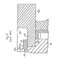
Boss 54 ofslant plate 50 includessmaller diameter portion 54a at an axially rearward end (to the right in Figure 1 and to the top in Figure 2) thereof, resulting in the formation ofannular shoulder 541 forward ofportion 54a. Annularbalance weight ring 500 is mounted aboutsmaller diameter portion 54a, in contact withshoulder 541.Balance weight ring 500 includesannular depression 501 formed at an inner periphery of the axially rearward surface, reducing the thickness ofring 500 at the inner periphery. Relativelythin plate portion 502 remains at the inner periphery ofbalance weight ring 500, forward ofdepression 501. With further reference to Figure 2annular groove 55 is formed in the radially outer peripheral surface ofsmaller diameter portion 54a, andannular snap ring 56 is disposed therein.Snap ring 56 includes annulartapered surface 56a formed at a radially inner portion of the axially rearward surface. Rearwardannular wall 55a ofannular groove 55 slants inwardly (to the left in Figure 2) at an angle generally corresponding to the angle of annulartapered surface 56a ofsnap ring 56 such thatsnap ring 56 may be slidably fitted and retained withingroove 55. The radially outer portion ofsnap ring 56 extends exteriorly ofgroove 55 and contacts thin-plate portion 502 ofbalance weight ring 500.Thin plate portion 502 ofbalance weight ring 500 is retained betweensnap ring 56 andannular shoulder 541. Therefore, balanceweight ring 500 is retained onboss 54. - However, when the compressor operates under unusual or extreme conditions, for example, when the rotational speed of the compressor is extremely high, when the rotational speed of the compressor is suddenly increased, or when refrigerant in the liquid state is present in the compressor, an extremely large force is produced which tends to cause
snap ring 56 to expand in the radially outer direction. As a result,snap ring 56 may slip out ofgroove 55, and out of contact withbalance weight ring 500. Without the retaining contact ofsnap ring 56, balanceweight ring 500 will slip off ofboss 54 and damage the internal elements of the compressor. - A solution to this problem using a second annular member disposed around the snap ring to retain the snap ring in place is claimed in published parent application, EP-A-0366349.
- US-A-4073603 discloses a slant plate type refrigerant compressor comprising a compressor housing including a cylinder block, the cylinder block including a plurality of peripherally disposed cylinders, a crank chamber enclosed within the cylinder block at a location forward of the cylinders, the compressor housing including a suction chamber and a discharge chamber formed therein, a piston slidably fitted within each of the cylinders, a drive mechanism coupled to the pistons to reciprocate the pistons within the cylinders, the drive mechanism including a drive shaft rotatably supported in the housing, the drive mechanism further including coupling means for coupling the drive shaft to the pistons such that rotary motion of the drive shaft is converted into reciprocating motion of the pistons in the cylinders, the coupling means including a slant plate disposed in the drive shaft and having a surface disposed at an inclined angle relative to the drive shaft, the slant plate having a boss, an annular balance weight disposed on the boss, and a retaining means for retaining the balance weight on the slant plate; and according to the present invention, such a compressor is characterised by the retaining means including an annular projection extending axially from the boss, a shoulder being formed about the annular projection, and the balance weight being disposed on the shoulder about the annular projection such that the projection is bent radially outwardly around the radially inner peripheral region of the balance weight to secure the balance weight on the boss of the slant plate.
- In the accompanying drawings:-
- Figure 1 shows a vertical longitudinal sectional view of a slant plate type refrigerant compressor in accordance with the prior art.
- Figure 2 shows an enlarged partial sectional view of the compressor shown in Figure 1 including the balance weight ring and retaining mechanism.
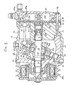
- Figure 3 shows a vertical longitudinal sectional view of a slant plate type refrigerant compressor in accordance with the present invention.
- Figures 4(a) and 4(b), respectively, show an enlarged partial sectional view before and after formation of the retaining mechanism as shown in Figure 3.
- In Figures 3-4, identical reference numerals are used to denote elements which are identical to the similarly numbered elements shown in prior art Figures 1 and 2. Additionally, although
compressor 10 is shown and is described with respect to Figures 3-4 as a wobble plate type compressor, the invention is not limited thereto and is applicable to any type of slant plate type compressor, including both fixed and variable capacity compressors of the wobble or swash plate type. Furthermore, in the following description, the left side of Figure 3, will be referred to as the front or forward side and the right side will be referred to as the rear side. The remaining Figures show views shifted by approximately 90°. The term "axial" refers to a direction parallel to the longitudinal axis of the drive shaft, and the term "radial" refers to the perpendicular direction. Of course all of the reference directions are made for the sake of convenience of description and are not intended to limit the invention in any way. - With reference to Figure 3, the construction of slant
plate type compressor 10 in accordance with the present invention is shown.Compressor 10 includescylindrical housing assembly 20 includingcylinder block 21,front end plate 23 disposed at one end ofcylinder block 21,crank chamber 22 formed betweencylinder block 21 andfront end plate 23, andrear end plate 24 disposed at the opposite end ofcylinder block 21.Front end plate 23 is mounted on the open forward end ofcylinder block 21 by a plurality ofbolts 101 to enclosecrank chamber 22 therein.Rear end plate 24 is mounted oncylinder block 21 at its opposite end by a plurality ofbolts 102. Valveplate 25 is located betweenrear end plate 24 andcylinder block 21.Opening 231 is centrally formed infront end plate 23.Drive shaft 26 is supported by bearing 30 disposed in opening 231.Central bore 210 extends throughcylinder block 21 to a rearward end surface. The inner (rear) end portion ofdrive shaft 26 is rotatably supported by bearing 31 disposed withincentral bore 210 ofcylinder block 21.Valve control mechanism 19 is disposed inbore 210 to the rear ofdrive shaft 26.Cam rotor 40 is fixed ondrive shaft 26 bypin member 261, and rotates withshaft 26. Thrust needle bearing 32 is disposed between the axial inner (rear) end surface offront end plate 23 and the adjacent forward axial end surface ofcam rotor 40.Cam rotor 40 includesarm 41 havingpin member 42 extending therefrom. Slantplate 50 is disposed aboutdrive shaft 26 and includes opening 53 through which driveshaft 26 passes. Slantplate 50 is disposedadjacent cam rotor 40.Slant plate 50 includesarm 51 havingslot 52, andboss 54.Cam rotor 40 andslant plate 50 are connected bypin member 42, which is inserted inslot 52 to create a hinged joint.Pin member 42 is slidable withinslot 52 to allow adjustment of the angular position ofslant plate 50 with respect to the longitudinal axis ofdrive shaft 26. - Wobble
plate 60 is mounted aboutboss 54 ofslant plate 50 throughbearings 61 and 62 so thatslant plate 50 is rotatable with respect thereto. Rotational motion ofslant plate 50 causes nutational motion ofwobble plate 60. Forkshaped slider 63 is attached to the outer peripheral end ofwobble plate 60 and is slidably mounted on slidingrail 64 held betweenfront end plate 23 andcylinder block 21. Fork shapedslider 63 prevents rotation ofwobble plate 60 andwobble plate 60 reciprocates alongrail 64 whencam rotor 40 andslant plate 50 rotate.Cylinder block 21 includes a plurality of peripherally locatedcylinder chambers 70 in whichpistons 71 reciprocate. Eachpiston 71 is connected towobble plate 60 at a peripheral location by acorresponding connecting rod 72. Nutational motion ofwobble plate 60 causespistons 71 to reciprocate incylinders 70 to compress refrigerant therein. -
Rear end plate 24 includes peripherally locatedannular suction chamber 241 and centrally locateddischarge chamber 251. Valveplate 25 is located betweencylinder block 21 andrear end plate 24 and includes a plurality of valvedsuction ports 242 linkingsuction chamber 241 withrespective cylinders 70. Valveplate 25 also includes a plurality ofvalved discharge ports 252 linkingdischarge chamber 251 withrespective cylinders 70.Suction ports 242 anddischarge ports 252 are provided with suitable reed valves as described in U.S. -A-4,011,029.Suction chamber 241 includes inlet portion 241 a which is connected to an evaporator of the external cooling circuit (not shown).Discharge chamber 251 is provided withoutlet portion 251 a connected to a condenser of the cooling circuit (not shown).Gaskets cylinder block 21 and the inner surface ofvalve plate 25, and the outer surface ofvalve plate 25 andrear end plate 24, respectively, to seal the mating surfaces ofcylinder block 21,valve plate 25 andrear end plate 24. -
Communication path 600links crank chamber 22 andsuction chamber 241 and includescentral bore 210 andpassageway 150.Valve control mechanism 19 controls the opening and closing ofcommunication path 600 in order to vary the capacity of the compressor, as disclosed in Japanese Patent Application Publication No. 01- 142,276. During operation ofcompressor 10,drive shaft 26 is rotated by the engine of the vehicle throughelectromagnetic clutch 300.Cam rotor 40 is rotated withdrive shaft 26, rotatingslant plate 50 as well, causingwobble plate 60 to nutate. Nutational motion ofwobble plate 60 reciprocatespistons 71 in theirrespective cylinders 70. Aspistons 71 are reciprocated, refrigerant gas which is introduced intosuction chamber 241 through inlet portion 241a, flows into eachcylinder 70 throughsuction ports 242 and is compressed therein. The compressed refrigerant gas is discharged intodischarge chamber 251 from eachcylinder 70 throughdischarge ports 252, and therefrom into the cooling circuit throughoutlet portion 251 a. The capacity ofcompressor 10 may be adjusted to maintain a constant pressure insuction chamber 241 in response to a change in the heat load of the evaporator, or a change in the rotating speed of the compressor. The capacity of the compressor is adjusted by changing the angle of the slant plate with respect to a plane perpendicular to the axis of the drive shaft. This angle is dependent upon the crank chamber pressure. An increase in crank chamber pressure decreases the slant angle of the slant plate and the wobble plate, decreasing the capacity of the compressor. A decrease in the crank chamber pressure increases the angle of the slant plate and the wobble plate and thus increases the capacity of the compressor. In the compressor shown in Fig. 3,variable capacity mechanism 19 acts in response to the crank chamber pressure, such that the acting point is modified according to the discharge pressure, to control the link between the crank and suction chambers, to adjust the crank chamber pressure and thereby change the slant angle ofslant plate 50 and vary the operating capacity of the compressor. Of course other types of variable displacement mechanisms, or none at all may be used in compressors according to the present invention. - With reference to Figures 3 and 4a-4b, a slant plate type compressor including a retaining mechanism in accordance with the present invention is shown. Balance
ring retaining mechanism 82 includesannular projection 549 integrally formed with and extending fromboss 54 ofslant plate 50.Shoulder 542 is formed onboss 54, aroundprojection 549.Thin plate portion 502 ofbalance weight ring 500 is disposed onshoulder 542 ofboss 54.Projection 549 is bent to extend around the radially inner periphery of annularthin plate portion 502 ofbalance weight ring 500, to securebalance weight ring 500 onboss 54. With reference to Figures 4-(a)-4(b), the formation of retaining mechanism 81 is shown.Boss 54 is formed such thatannular projection 549 extends substantially axially from the rear surface, formingannular shoulder 542 exteriorly thereof.Annular projection 549 is relatively thin and is made of a soft metal, for example, untempered iron, such that it may be bent by a press work (not shown). The outer diameter ofannular projection 549 is selected to be slightly smaller than the inner diameter ofbalance weight ring 500 such thatthin plate portion 502 may be disposed onshoulder 542. Afterthin plate portion 502 is disposed onshoulder 542,annular projection 549 is bent radially outwardly bymold 100 of the press work so as to clampthin plate portion 502 againstshoulder 542. Since the need for a snap ring is eliminated,balance weight ring 500 is securely retained onslant plate 50, even when the compressor operates under unusual conditions.
Claims (5)
Applications Claiming Priority (5)
| Application Number | Priority Date | Filing Date | Title |
|---|---|---|---|
| JP138134/88 | 1988-10-25 | ||
| JP13813688U JPH0338458Y2 (en) | 1988-10-25 | 1988-10-25 | |
| JP1988138134U JPH082471Y2 (en) | 1988-10-25 | 1988-10-25 | Variable capacity compressor |
| JP138136/88 | 1988-10-25 | ||
| EP89310709A EP0366349B1 (en) | 1988-10-25 | 1989-10-18 | Slant plate type compressor |
Related Parent Applications (1)
| Application Number | Title | Priority Date | Filing Date |
|---|---|---|---|
| EP89310709.4 Division | 1989-10-18 |
Publications (3)
| Publication Number | Publication Date |
|---|---|
| EP0499343A2 true EP0499343A2 (en) | 1992-08-19 |
| EP0499343A3 EP0499343A3 (en) | 1993-03-31 |
| EP0499343B1 EP0499343B1 (en) | 1994-09-14 |
Family
ID=26471255
Family Applications (4)
| Application Number | Title | Priority Date | Filing Date |
|---|---|---|---|
| EP92201238A Expired - Lifetime EP0499343B1 (en) | 1988-10-25 | 1989-10-18 | Slant plate type compressor |
| EP89310709A Expired - Lifetime EP0366349B1 (en) | 1988-10-25 | 1989-10-18 | Slant plate type compressor |
| EP92201235A Expired - Lifetime EP0499341B1 (en) | 1988-10-25 | 1989-10-18 | Slant plate type compressor |
| EP92201237A Expired - Lifetime EP0499342B1 (en) | 1988-10-25 | 1989-10-18 | Slant plate type compressor |
Family Applications After (3)
| Application Number | Title | Priority Date | Filing Date |
|---|---|---|---|
| EP89310709A Expired - Lifetime EP0366349B1 (en) | 1988-10-25 | 1989-10-18 | Slant plate type compressor |
| EP92201235A Expired - Lifetime EP0499341B1 (en) | 1988-10-25 | 1989-10-18 | Slant plate type compressor |
| EP92201237A Expired - Lifetime EP0499342B1 (en) | 1988-10-25 | 1989-10-18 | Slant plate type compressor |
Country Status (7)
| Country | Link |
|---|---|
| US (2) | US5062772A (en) |
| EP (4) | EP0499343B1 (en) |
| KR (1) | KR970003247B1 (en) |
| CN (1) | CN1017272B (en) |
| AU (5) | AU622494B2 (en) |
| CA (1) | CA2001119C (en) |
| DE (4) | DE68920053T2 (en) |
Cited By (1)
| Publication number | Priority date | Publication date | Assignee | Title |
|---|---|---|---|---|
| US9279325B2 (en) | 2012-11-08 | 2016-03-08 | General Electric Company | Turbomachine wheel assembly having slotted flanges |
Families Citing this family (9)
| Publication number | Priority date | Publication date | Assignee | Title |
|---|---|---|---|---|
| DE4211695C2 (en) * | 1991-04-08 | 1996-11-14 | Zexel Corp | Swash plate compressor |
| JP3026518B2 (en) * | 1991-07-03 | 2000-03-27 | サンデン株式会社 | Variable capacity rocking plate compressor |
| DE4405034A1 (en) * | 1994-02-17 | 1995-08-24 | Audi Ag | Axial piston swash plate compressor |
| JPH09151846A (en) * | 1995-11-30 | 1997-06-10 | Sanden Corp | Variable displacement cam plate type compressor |
| JPH11201033A (en) * | 1998-01-12 | 1999-07-27 | Sanden Corp | Swash plate type compressor |
| US6823768B2 (en) | 2001-11-22 | 2004-11-30 | Sanden Corporation | Nitrided surface layer on a swash plate boss |
| US8091240B2 (en) | 2007-07-04 | 2012-01-10 | Nsk Ltd. | Assembling method of bearing unit |
| JP5065158B2 (en) * | 2008-06-02 | 2012-10-31 | サンデン株式会社 | Swing plate type variable capacity compressor |
| DE102015217443A1 (en) * | 2015-09-11 | 2017-03-30 | Bosch Mahle Turbo Systems Gmbh & Co. Kg | bearing housing |
Citations (8)
| Publication number | Priority date | Publication date | Assignee | Title |
|---|---|---|---|---|
| DE1079577B (en) * | 1956-07-14 | 1960-04-14 | Friedrich Wilhelm Kiekert | Method and tool for producing a fixed connection between a sheet metal wall and a bushing provided with a flange |
| FR2224649A1 (en) * | 1973-04-04 | 1974-10-31 | Borg Warner | |
| FR2362285A1 (en) * | 1976-02-06 | 1978-03-17 | Borg Warner | AXIAL PISTON COMPRESSOR WITH VARIABLE CYLINDER |
| FR2371252A1 (en) * | 1976-11-22 | 1978-06-16 | Letang & Remy Ets | Reinforcing plate fixture for sheet metal - has stepped punch forced through both parts to form hollow rivet from metal sheet |
| GB2003991A (en) * | 1977-09-12 | 1979-03-21 | Borg Warner | Variable capacity wobble plate compressor |
| EP0102691A1 (en) * | 1982-08-02 | 1984-03-14 | Diesel Kiki Co., Ltd. | Variable displacement compressor |
| JPS59131022A (en) * | 1983-01-14 | 1984-07-27 | Toshiba Corp | Hollow rotary device |
| GB2208242A (en) * | 1987-07-20 | 1989-03-15 | Sanden Corp | Wobble plate type compressor |
Family Cites Families (23)
| Publication number | Priority date | Publication date | Assignee | Title |
|---|---|---|---|---|
| US2182740A (en) * | 1937-12-18 | 1939-12-05 | Internat Supply Company | Counterbalance for crankshafts |
| US2776627A (en) * | 1952-07-10 | 1957-01-08 | Vickers Inc | Power transmission |
| US3055100A (en) * | 1957-07-01 | 1962-09-25 | Zeller Corp | Method of forming interlocking joint between telescoped members |
| US3183848A (en) * | 1962-05-09 | 1965-05-18 | Hydro Kinetics Inc | Cartridge type pumping apparatus |
| US3246577A (en) * | 1963-12-23 | 1966-04-19 | Sundstrand Corp | Piston return mechanism |
| US4008005A (en) * | 1974-07-31 | 1977-02-15 | Sankyo Electric Company, Limited | Refrigerant compressor |
| IT1060943B (en) * | 1975-03-13 | 1982-09-30 | Central Automotive Ind | REFRIGERANT GAS COMPRESSOR WITH LUBRICATION SYSTEM FOR AIR CONDITIONERS OF VEHICLES AND OTHER |
| DE2611218A1 (en) * | 1976-03-17 | 1977-10-06 | Kugelfischer G Schaefer & Co | FORM AND FORCE-LOCKING CONNECTION OF ROLLER BEARING PARTS WITH SURROUNDING PARTS |
| JPS53410A (en) * | 1976-06-23 | 1978-01-06 | Sanden Corp | Swinging type compressor |
| JPS54108009A (en) * | 1978-02-10 | 1979-08-24 | Sanden Corp | Oscillating compressor |
| JPS5823029Y2 (en) * | 1978-07-01 | 1983-05-17 | サンデン株式会社 | cooling compressor |
| NL7900076A (en) * | 1979-01-05 | 1980-07-08 | Philips Nv | DRIVING FOR A MACHINE WITH PISTON AND REVERSE PISTONS WITH VARIABLE STROKE. |
| DE3326491A1 (en) * | 1983-07-22 | 1985-02-07 | Skf Kugellagerfabriken Gmbh, 8720 Schweinfurt | METHOD AND DEVICE FOR FIXING MACHINE PARTS |
| JPH0646018B2 (en) * | 1985-01-23 | 1994-06-15 | 株式会社日立製作所 | Fuel atomizer |
| US4771676A (en) * | 1986-05-19 | 1988-09-20 | Toshiba Kikai Kabushiki Kaisha | Hydraulic transmission device |
| JPS6316177A (en) * | 1986-07-08 | 1988-01-23 | Sanden Corp | Variable displacement type compressor |
| JPS6351172U (en) * | 1986-09-19 | 1988-04-06 | ||
| JPH0223829Y2 (en) * | 1987-05-19 | 1990-06-28 | ||
| JP2511056B2 (en) * | 1987-07-23 | 1996-06-26 | サンデン株式会社 | Variable capacity swash plate compressor |
| JPS6429679A (en) * | 1987-07-24 | 1989-01-31 | Sanden Corp | Capacity variable swash plate type compressor |
| JPH01142276A (en) * | 1987-11-27 | 1989-06-05 | Sanden Corp | Variable displacement swash-plate type compressor |
| JP2503569B2 (en) * | 1988-02-24 | 1996-06-05 | 株式会社豊田自動織機製作所 | Wobble type compressor drive controller |
| US4893994A (en) * | 1989-05-25 | 1990-01-16 | General Motors Corporation | Guide assembly and guide shoe for a variable angle wobble plate compressor |
-
1989
- 1989-10-18 EP EP92201238A patent/EP0499343B1/en not_active Expired - Lifetime
- 1989-10-18 DE DE68920053T patent/DE68920053T2/en not_active Expired - Fee Related
- 1989-10-18 DE DE8989310709T patent/DE68905750T2/en not_active Expired - Fee Related
- 1989-10-18 EP EP89310709A patent/EP0366349B1/en not_active Expired - Lifetime
- 1989-10-18 EP EP92201235A patent/EP0499341B1/en not_active Expired - Lifetime
- 1989-10-18 DE DE68918954T patent/DE68918954T2/en not_active Expired - Fee Related
- 1989-10-18 EP EP92201237A patent/EP0499342B1/en not_active Expired - Lifetime
- 1989-10-18 DE DE68918290T patent/DE68918290T2/en not_active Expired - Fee Related
- 1989-10-20 US US07/424,691 patent/US5062772A/en not_active Expired - Lifetime
- 1989-10-20 AU AU43608/89A patent/AU622494B2/en not_active Ceased
- 1989-10-20 CA CA002001119A patent/CA2001119C/en not_active Expired - Fee Related
- 1989-10-24 KR KR1019890015253A patent/KR970003247B1/en not_active IP Right Cessation
- 1989-10-25 CN CN89108230A patent/CN1017272B/en not_active Expired
-
1991
- 1991-05-23 US US07/705,056 patent/US5106271A/en not_active Expired - Lifetime
-
1992
- 1992-01-22 AU AU10390/92A patent/AU631757B2/en not_active Ceased
- 1992-01-22 AU AU10389/92A patent/AU631756B2/en not_active Ceased
- 1992-01-22 AU AU10388/92A patent/AU1038892A/en not_active Abandoned
- 1992-01-22 AU AU10391/92A patent/AU631758B2/en not_active Ceased
Patent Citations (8)
| Publication number | Priority date | Publication date | Assignee | Title |
|---|---|---|---|---|
| DE1079577B (en) * | 1956-07-14 | 1960-04-14 | Friedrich Wilhelm Kiekert | Method and tool for producing a fixed connection between a sheet metal wall and a bushing provided with a flange |
| FR2224649A1 (en) * | 1973-04-04 | 1974-10-31 | Borg Warner | |
| FR2362285A1 (en) * | 1976-02-06 | 1978-03-17 | Borg Warner | AXIAL PISTON COMPRESSOR WITH VARIABLE CYLINDER |
| FR2371252A1 (en) * | 1976-11-22 | 1978-06-16 | Letang & Remy Ets | Reinforcing plate fixture for sheet metal - has stepped punch forced through both parts to form hollow rivet from metal sheet |
| GB2003991A (en) * | 1977-09-12 | 1979-03-21 | Borg Warner | Variable capacity wobble plate compressor |
| EP0102691A1 (en) * | 1982-08-02 | 1984-03-14 | Diesel Kiki Co., Ltd. | Variable displacement compressor |
| JPS59131022A (en) * | 1983-01-14 | 1984-07-27 | Toshiba Corp | Hollow rotary device |
| GB2208242A (en) * | 1987-07-20 | 1989-03-15 | Sanden Corp | Wobble plate type compressor |
Non-Patent Citations (1)
| Title |
|---|
| PATENT ABSTRACTS OF JAPAN vol. 8, no. 258 (M-340)(1695) 27 November 1984 & JP-A-59 131 022 ( TOSHIBA ) * |
Cited By (1)
| Publication number | Priority date | Publication date | Assignee | Title |
|---|---|---|---|---|
| US9279325B2 (en) | 2012-11-08 | 2016-03-08 | General Electric Company | Turbomachine wheel assembly having slotted flanges |
Also Published As
Similar Documents
| Publication | Publication Date | Title |
|---|---|---|
| EP0410453B1 (en) | Lubricating mechanism for a piston assembly of a slant plate type compressor | |
| EP0372913B1 (en) | Wobble plate compressor | |
| EP0486257B1 (en) | Slant plate type compressor with variable capacity control mechanism | |
| EP0318316B1 (en) | Slant plate type compressor with variable displacement mechanism | |
| US4960366A (en) | Slant plate type compressor with variable displacement mechanism | |
| EP0292288B1 (en) | Variable displacement compressor with biased inclined member | |
| EP0405878B1 (en) | Slant plate type compressor with variable displacement mechanism | |
| EP0845593B1 (en) | Slant plate type compressor with variable capacity control mechanism | |
| US4913627A (en) | Wobble plate type compressor with variable displacement mechanism | |
| EP0653563B1 (en) | Slant plate type compressor with variable displacement mechanism | |
| EP0499343B1 (en) | Slant plate type compressor | |
| US5255569A (en) | Slant plate type compressor with variable displacement mechanism | |
| EP0339897B1 (en) | Slant plate type compressor with variable displacement mechanism | |
| EP0318976B1 (en) | Slant plate type compressor with variable displacement mechanism | |
| EP0844389B1 (en) | Swash plate compressor | |
| US5299918A (en) | Bearing for compressor drive shaft | |
| US6378417B1 (en) | Swash plate compressor in which an opening edge of each cylinder bore has a plurality of chamferred portions |
Legal Events
| Date | Code | Title | Description |
|---|---|---|---|
| PUAI | Public reference made under article 153(3) epc to a published international application that has entered the european phase |
Free format text: ORIGINAL CODE: 0009012 |
|
| AC | Divisional application: reference to earlier application |
Ref document number: 366349 Country of ref document: EP |
|
| AK | Designated contracting states |
Kind code of ref document: A2 Designated state(s): DE FR GB IT SE |
|
| PUAL | Search report despatched |
Free format text: ORIGINAL CODE: 0009013 |
|
| AK | Designated contracting states |
Kind code of ref document: A3 Designated state(s): DE FR GB IT SE |
|
| 17P | Request for examination filed |
Effective date: 19930924 |
|
| 17Q | First examination report despatched |
Effective date: 19940103 |
|
| GRAA | (expected) grant |
Free format text: ORIGINAL CODE: 0009210 |
|
| AC | Divisional application: reference to earlier application |
Ref document number: 366349 Country of ref document: EP |
|
| AK | Designated contracting states |
Kind code of ref document: B1 Designated state(s): DE FR GB IT SE |
|
| ET | Fr: translation filed | ||
| REF | Corresponds to: |
Ref document number: 68918290 Country of ref document: DE Date of ref document: 19941020 |
|
| ITF | It: translation for a ep patent filed |
Owner name: JACOBACCI CASETTA & PERANI S.P.A. |
|
| EAL | Se: european patent in force in sweden |
Ref document number: 92201238.0 |
|
| PLBE | No opposition filed within time limit |
Free format text: ORIGINAL CODE: 0009261 |
|
| STAA | Information on the status of an ep patent application or granted ep patent |
Free format text: STATUS: NO OPPOSITION FILED WITHIN TIME LIMIT |
|
| 26N | No opposition filed | ||
| PGFP | Annual fee paid to national office [announced via postgrant information from national office to epo] |
Ref country code: SE Payment date: 20011005 Year of fee payment: 13 |
|
| PGFP | Annual fee paid to national office [announced via postgrant information from national office to epo] |
Ref country code: FR Payment date: 20011010 Year of fee payment: 13 |
|
| PGFP | Annual fee paid to national office [announced via postgrant information from national office to epo] |
Ref country code: GB Payment date: 20011017 Year of fee payment: 13 |
|
| PGFP | Annual fee paid to national office [announced via postgrant information from national office to epo] |
Ref country code: DE Payment date: 20011105 Year of fee payment: 13 |
|
| REG | Reference to a national code |
Ref country code: GB Ref legal event code: IF02 |
|
| PG25 | Lapsed in a contracting state [announced via postgrant information from national office to epo] |
Ref country code: GB Free format text: LAPSE BECAUSE OF NON-PAYMENT OF DUE FEES Effective date: 20021018 |
|
| PG25 | Lapsed in a contracting state [announced via postgrant information from national office to epo] |
Ref country code: SE Free format text: LAPSE BECAUSE OF NON-PAYMENT OF DUE FEES Effective date: 20021019 |
|
| PG25 | Lapsed in a contracting state [announced via postgrant information from national office to epo] |
Ref country code: DE Free format text: LAPSE BECAUSE OF NON-PAYMENT OF DUE FEES Effective date: 20030501 |
|
| EUG | Se: european patent has lapsed | ||
| GBPC | Gb: european patent ceased through non-payment of renewal fee |
Effective date: 20021018 |
|
| PG25 | Lapsed in a contracting state [announced via postgrant information from national office to epo] |
Ref country code: FR Free format text: LAPSE BECAUSE OF NON-PAYMENT OF DUE FEES Effective date: 20030630 |
|
| REG | Reference to a national code |
Ref country code: FR Ref legal event code: ST |
|
| PG25 | Lapsed in a contracting state [announced via postgrant information from national office to epo] |
Ref country code: IT Free format text: LAPSE BECAUSE OF NON-PAYMENT OF DUE FEES;WARNING: LAPSES OF ITALIAN PATENTS WITH EFFECTIVE DATE BEFORE 2007 MAY HAVE OCCURRED AT ANY TIME BEFORE 2007. THE CORRECT EFFECTIVE DATE MAY BE DIFFERENT FROM THE ONE RECORDED. Effective date: 20051018 |