EP0507269A2 - Writing device for storing handwriting - Google Patents
Writing device for storing handwriting Download PDFInfo
- Publication number
- EP0507269A2 EP0507269A2 EP92105599A EP92105599A EP0507269A2 EP 0507269 A2 EP0507269 A2 EP 0507269A2 EP 92105599 A EP92105599 A EP 92105599A EP 92105599 A EP92105599 A EP 92105599A EP 0507269 A2 EP0507269 A2 EP 0507269A2
- Authority
- EP
- European Patent Office
- Prior art keywords
- writing
- handwriting
- writing device
- storing
- set forth
- Prior art date
- Legal status (The legal status is an assumption and is not a legal conclusion. Google has not performed a legal analysis and makes no representation as to the accuracy of the status listed.)
- Granted
Links
Images


Classifications
-
- G—PHYSICS
- G06—COMPUTING; CALCULATING OR COUNTING
- G06F—ELECTRIC DIGITAL DATA PROCESSING
- G06F3/00—Input arrangements for transferring data to be processed into a form capable of being handled by the computer; Output arrangements for transferring data from processing unit to output unit, e.g. interface arrangements
- G06F3/01—Input arrangements or combined input and output arrangements for interaction between user and computer
- G06F3/03—Arrangements for converting the position or the displacement of a member into a coded form
- G06F3/033—Pointing devices displaced or positioned by the user, e.g. mice, trackballs, pens or joysticks; Accessories therefor
- G06F3/038—Control and interface arrangements therefor, e.g. drivers or device-embedded control circuitry
- G06F3/0386—Control and interface arrangements therefor, e.g. drivers or device-embedded control circuitry for light pen
-
- G—PHYSICS
- G06—COMPUTING; CALCULATING OR COUNTING
- G06F—ELECTRIC DIGITAL DATA PROCESSING
- G06F3/00—Input arrangements for transferring data to be processed into a form capable of being handled by the computer; Output arrangements for transferring data from processing unit to output unit, e.g. interface arrangements
- G06F3/01—Input arrangements or combined input and output arrangements for interaction between user and computer
- G06F3/03—Arrangements for converting the position or the displacement of a member into a coded form
- G06F3/033—Pointing devices displaced or positioned by the user, e.g. mice, trackballs, pens or joysticks; Accessories therefor
- G06F3/0354—Pointing devices displaced or positioned by the user, e.g. mice, trackballs, pens or joysticks; Accessories therefor with detection of 2D relative movements between the device, or an operating part thereof, and a plane or surface, e.g. 2D mice, trackballs, pens or pucks
- G06F3/03545—Pens or stylus
-
- G—PHYSICS
- G06—COMPUTING; CALCULATING OR COUNTING
- G06V—IMAGE OR VIDEO RECOGNITION OR UNDERSTANDING
- G06V10/00—Arrangements for image or video recognition or understanding
- G06V10/10—Image acquisition
- G06V10/12—Details of acquisition arrangements; Constructional details thereof
Definitions
- the present invention relates to a novel writing device for storing handwriting.
- the information is generally written as characters, figures and the like on paper and the like using a writing device such as a ball point pen, a propelling pencil and the like, then the paper and the like are preserved.
- an inputting device such as a keyboard, a mouse, a digitizer, a touch panel, a light-pen and the like are provided for inputting representations of human intention in an electric processing apparatus such as a computer and the like.
- a writing device represented by a pen is used as one means for communicating one's mind to another person.
- the writing device can be used by any person. But information written by the writing device cannot be directly input to an electric processing apparatus such as a computer and the like. A disadvantage arises that a character recognition apparatus, a keyboard or the like additionally is required.
- an input device for a computer utilizing processings may be various devices such as a keyboard, a mouse, a digitizer, a pen utilized input apparatus or the like, as has been mentioned earlier.
- the input device is not sufficiently convenient for supporting a noting which is a result of writing in the ordinary behavior of a man.
- An electric memorandum device is useful in supporting the noting function but is quite different from writing information resulting from using the writing device. That is, a writing device such as a pen, a pencil, a writing brush or the like is the most superior device because a man can use the writing device with ease.
- An input device is required having the similar advantage as of the writing device. When the writing device is employed to write information on paper, the paper on which information are written can easily handed to another person. Further, the thinking of man is remarkably influenced by language and expressions. There is strong demand for a device which can be used for handing a thinking process to another person, accordingly.
- a writing device for storing handwriting comprises; writing means, handwriting detection means for detecting a locus of a character, a figure and the like which is written by the writing means, storing means for storing the detected locus, and casing means for housing the writing means, the handwriting detection means and the storing means therein.
- the writing means may be a writing device means such as a pencil, a pen, a ball point pen, a crayon, a piece of chalk and the like for writing a thin line or a thick line.
- the writing device means may include water-color ink, oil based ink, water base paint, oil paint or the like.
- the writing device means may have an arrangement such that a writing section at its edge is exchangeable, or a writing section at its edge is able to be delivered outwardly.
- the ink, the paint or the like may be housed in a cartridge or may be directly supplied to the writing section.
- the line may be colored with an arbitrary color. In this case, it is preferable that the handwriting detection means detect the arbitrary color.
- a character, a figure or the like is written on paper and the like by grasping the casing of the writing means.
- the character, a locus of the figure or the like is detected by the handwriting detection means.
- the detected locus is stored by the storing means.
- the handwriting detection means include an optical sensor for optically detecting handwriting written on paper or the like, a stress sensor such as a piezoelectric transducer, a strain gauge and the like for detecting force applied to the writing means during a writing operation and locus detection means for detecting the locus of the writing means based on signals output from the optical sensor and the stress sensor.
- a stress sensor such as a piezoelectric transducer, a strain gauge and the like for detecting force applied to the writing means during a writing operation
- locus detection means for detecting the locus of the writing means based on signals output from the optical sensor and the stress sensor.
- the locus of the writing means is detected by the locus detection means based on signals output from the stress sensor and/or the optical sensor.
- the locus detection means based on signals output from the optical sensor. Consequently, the locus from beginning to end is detected without interruption, even when the writing means is separated from the paper or the like during handwriting.
- the optical sensor may include a lens, an optical fiber and a charge coupled device chip (hereinafter referred to as CCD chip).
- the optical sensor may include three lenses which are disposed at every 120 degrees in shifted positions with respect to the writing means.
- the optical sensor may include a lens which surrounds the writing means and a CCD chip which also surrounds the writing means.
- the optical sensor may include only a CCD chip which surrounds the writing means.
- the writing device for storing handwriting include at least one pair of lenses which are disposed synmetrically with respect to the writing means, a CCD chip and image compensation means for obtaining an image of the edge of the writing means based on image signals corresponding to each lens obtained by the CCD chip.
- the handwriting detection means may include an optical sensor and locus detection means.
- the handwriting detection means may be a gyrocompass.
- the writing means may be means to draw lines using ink which includes a magnetic substance and the handwriting detection means may be a magnetic sensor.
- the casing means includes two casing part means which are removably connected to one another and the storing means is housed in one of the casing part means.
- the writing means, the handwriting detection means and the storing means are housed in the casing means.
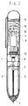
- Figure 1 is a cross-sectional view showing an inner mechanism of a writing device for storing handwriting according to a first embodiment of the present invention.
- a core 2 of a ball point pen is provided in the center of a lower portion of a cylindrical casing 1.
- the core 2 is arranged to move freely outwardly and inwardly of the casing through an opening 5 which is formed at the bottom edge of the casing 1, by a coil spring 3 and an operative projection 4.
- Three lenses 6x, 6y and 6z ( Figure 2) are provided at the bottom edge of the casing 1.
- Three lenses are projected outward and are arranged at every 120 degrees with respect to the core 2. Light collected by these lenses 6x, 6y and 6z is guided by optical fibers 7 to a lens 9 which is disposed with respect to a circuit board 8 housed in an inner upper portion of the casing 1.
- Piezoelectric transducers 13x, 13y and 13z are provided at the bottom edge of the casing 1. Three piezoelectric transducers 13x, 13y and 13z contact the core 2 and are arranged at every 120 degrees with respect to the core 2. Strain signals output from the piezoelectric transducers 13x, 13y and 13z are transmitted and input in the electrical circuitry section 12 through lead wires 14.
- the electrical circuitry section 12 includes standard timing pulse generation circuitry and counting circuitry which measure and record the passage of time during which strain signals are generated by the piezoelectric transducers 13x, 13y and 13z.
- Reference numerals 15 and 16 indicate a battery and a power switch, respectively.
- Figure 3 shows a circuit arrangement of the electrical circuitry section 12.
- the electrical circuitry section 12 includes handwriting detection circuitry 21, handwriting compression circuitry 22, a handwriting storing section 23 and a read out control section 24.
- the handwriting detection circuitry 21 detects the locus of the ball point pen based on signals output from an optical sensor 17 which includes lenses 6x, 6y and 6z, the optical fibers 7, the lens 9 and the CCD chip 10, and a sensor 13 which includes piezoelectric transducers 13x, 13y and 13z. More particularly, for example, the moving direction of the writing device can be detected based on signals output from the piezoelectric transducers 13x, 13y and 13z. The moving direction of the writing device can also be detected based on images obtained by the optical sensor 17.
- the distance moved by the writing device can be detected based on a continuing time period of a predetermined combination of the signals output from the piezoelectric transducers 13x, 13y and 13z.
- the distance moved by the writing device can also be detected based on images obtained by the optical sensor 17.
- the handwriting compression circuitry 22 compresses a detected signal indicative of handwriting.
- the handwriting storing section 23 stores the compressed signal indicative of handwriting.
- the read out control section 24 reads out the compressed signal indicative of handwriting and outputts therefrom.
- the core 2 is apart from the paper 25 and moves in upper direction to write the remaining portion
- the moving direction and the moving distance, under the condition that the core 2 is apart from the paper 25, are detected by the optical sensor 17.
- a viewing region of the optical sensor 17 is illustrated by a circle A
- the prior written locus is illustrated by a line B having an end point a and the next contacting point is illustrated by a point b .
- the relative position and distance of the point b with respect to the end point a is detected by the optical sensor 17.
- the handwriting detection circuitry 21 detects a series of handwriting including the contacted portion and non-contacted portion based on signals output from the sensor 13 and the optical sensor 17.
- the handwriting detection signal is compressed by thinning or the like by the handwriting compression circuitry 22 and the compressed handwriting signal is stored in the handwriting storing section 23 sequentially.
- the writing device When the writing device is employed, it is sufficient to bring only the writing device even when a man goes anywhere such as on his way to store contents as they are which are written on paper or the like because the writing device stores handwriting of characters, figures and the like in the handwriting storing section 23 which is incorporated in the writing device 1. It is preferable that a switch or the like is further provided for indicating punctuation of a character, figure or the like.
- Figure 7 is a cross-sectional view showing an inner mechanism of a writing device for storing handwriting according to a second embodiment of the present invention, while figure 8 is a bottom view thereof.
- the writing device shown in fig. 7 differs from the embodiment shown in fig. 1 in that a CCD chip 10 having smaller size is employed, the circuit board 8 is disposed horizontally, and the lens 9 is disposed beneath the circuit board 8. The lens 9 is opposite to the CCD chip 10, in the vertical direction.
- the writing device shown in fig. 7 can be smaller in size than the writing device shown in fig. 1 which has a large upper portion due to its large size CCD chip 10.
- the writer can reproduce the original characters, figures and the like to some degree by displaying or printing out the handwriting read out from the handwriting storing section 23.
- the original characters, figures and the like can be perfectly reproduced by supplying the handwriting read out from the handwriting storing section 23 to an apparatus 30 which is shown in fig. 9.
- the apparatus 30 includes a read out section 31, a handwriting reproduction section 32, a character recognition section 33, a figure recognition section 34 and an image processing section 35.
- the read out section 31 reads data representative of handwriting out from the writing device 1.
- the handwriting reproduction section 32 perfectly reproduces data representative of the original handwriting based on the read out data.
- the character recognition section 33, the figure recognition section 34 and the image processing section 35 cooperate or selectively operate to securely reproduce meaning information in the read out data.
- the reproduced meaning information are input in a computer 36 or an electic noting apparatus 37. That is, the contents stored in the handwriting storing section 23 of the writing device 1 can be input, as they are, to an electric processing apparatus such as a computer without any keyboard, character input apparatus or the like.
- Figure 10 is a cross-sectional view showing a mechanism at a bottom edge portion of a writing device for storing handwriting according to a third embodiment of the present invention.
- the writing device for storing handwriting has a simplified optical arrangement as follows.
- a casing 41 of the writing device has an opening 42 at its bottom edge.
- a light collecting lens 43 is provided in the opening 42, the lens 43 having a through hole at its optical central axis so as to have a ring shape.
- a light receiving device 44 such as a CCD chip or the like is provided above lens 43 in a close position with respect to the light collecting lens 43.
- the light receiving device 44 has a through hole at its optical central axis so as to have a ring shape.
- a core 45 of a ball point pen is disposed in the casing 41 in a manner so that it is movable out and in with respect to the opening 42 through the light collecting lens 43 and the light receiving device 44.
- the light receiving device 44 receives light and transforms the received light to electrical signals which are guided to the electrical circuitry section 12 through lead wires 46.
- an image within a predetermined region surrounding the leading edge of the ball point pen is obtained by the light collecting lens 43 and the light receiving device 44.
- the locus of the leading edge of the ball point pen is optically detected and stored based on the image.
- the embodiment overcomes disadvantages such as difficulty in connecting optical fibers at a narrow spaced portion of the writing device and the like because signals output from the light receiving device 44 are transmitted to the electrical circuitry section 12 through lead wires 46.
- Figure 11(A) is a cross-sectional view showing a mechanism at a bottom edge portion of a writing device for storing handwriting according to a fourth embodiment of the present invention.
- the embodiment differs from the embodiment shown in fig. 10 in that the light collecting lens 43 is omitted. That is, the light receiving device 44 such as a CCD chip or the like is provided in the opening 42, the light receiving device 44 having a through hole at its optical central axis so as to have a ring shape (refer to fig. 11(B)).
- the core 45 of a ball point pen is disposed in the casing 41 in a manner so that it is movable out and in with respect to the opening 42 through the light receiving device 44. Electrical signals output from the light receiving device 44 are guided to the electrical circuitry section 12 through lead wires 46.
- the light receiving device 44 may have three fan-shaped light receiving components 44a, 44b and 44c which are combined to form a ring shape as a whole (refer to fig. 11(C)).
- Figure 12 is a cross-sectional view showing a mechanism at a bottom edge portion of a writing device for storing handwriting according to a fifth embodiment of the present invention.
- a casing 51 of the writing device has an opening 52 at its bottom edge and a core 53 of a ball point pen in a manner so that it is movable out and in with respect to the opening 52.
- Two light collecting lenses 54a and 54b are provided at the bottom edge portion of the casing 51 in a projected outward manner.
- the two light collecting lenses 54a and 54b are synmetrically disposed with respect to the core 53.
- Optical signals representative of handwriting received by these lenses 54a and 54b are guided to a light receiving face of a light receiving device such as a CCD chip or the like which is disposed over the lenses 54a and 54b through two bandled optical fibers 55a and 55b.
- the lenses 54a and 54b have dead angles due to the core 53 of the ball point pen (refer to hatching portions in fig. 13). But the dead angles are compensated by overlapping images obtained by corresponding lenses 54a and 54b so as to obtain an image corresponding to the leading edge portion of the core 53. Handwriting of the core 53 is sufficiently stored in the handwriting storing section 23.
- Figure 14(A) is a plan view showing a mechanism at a bottom edge portion of a writing device for storing handwriting according to a sixth embodiment of the present invention, while figure 14(B) is a side view thereof.
- Fig. 14(A) illustrates only a core 61 of a ball point pen, an x-piezoelectric transducer 62x and a y-piezoelectric transducer 62y.
- the x-piezoelectric transducer 62x and the y-piezoelectric transducer 62y are disposed at a 90 degrees shifted position with respect to one another and with respect to the core 61 (z-axis).
- the x-piezoelectric transducer 62x and the y-piezoelectric transducer 62y are push-pull type piezoelectric transducers and sensitive to stress caused by pushing and pulling. Strain within 360 degrees with respect to the core 61 (z-axis) are detectable by these piezoelectric transducers 62x and 62y.
- Piezoelectric transducers 62x and 62y are disposed in an inclined condition with respect to the z-axis. Components in the z-axis direction are accordingly detected as stress signals even when handwriting is obtained without moving the core 61 in a x-axis direction and a y-axis direction on paper, such as by making a dot.
- Figure 15 is a cross-sectional view showing an inner arrangement at a top edge portion of a writing device for storing handwriting according to a seventh embodiment of the present invention.
- the writing device includes a cylindrical casing 71 and an upper casing 72 which is removably mounted to the top portion of the cylindrical casing 71.
- the upper casing 72 includes a handwriting storing section 73 therein which has a connecting plug 74 at one body.
- the connecting plug 74 is inserted to a connecter 75 provided at the top edge of the cylindrical casing 71 so as to electrically connect the handwriting storing section 73 with an electrical circuitry section housed in the cylindrical casing 71.
- the upper casing 72 is a removable cartridge-type casing for removably mounting the handwriting storing section 73.
- the handwriting storing section 73 can be replaced with a new one when the handwriting storing section 73 fully stores handwriting. Consequently, the handwriting in a long sentence and/or figure can be stored without being limited by the memory capacity of the handwriting storing section 73.
- a gyrocompass also may be used to detect handwriting.
- moving of the writing device can be detected nevertheless, whether the writing device contacts with paper or the like or not.
- the locus of the core of the writing device can be detected by utilizing the rotation of a ball of a ball point pen, flowing quantity of ink, or reaction at the leading edge of the writing device.
Abstract
Description
- The present invention relates to a novel writing device for storing handwriting.
- When a lot of information is to be kept with ease, the information is generally written as characters, figures and the like on paper and the like using a writing device such as a ball point pen, a propelling pencil and the like, then the paper and the like are preserved.
- On the other hand, an inputting device such as a keyboard, a mouse, a digitizer, a touch panel, a light-pen and the like are provided for inputting representations of human intention in an electric processing apparatus such as a computer and the like.
- A writing device represented by a pen is used as one means for comunicating one's mind to another person. The writing device can be used by any person. But information written by the writing device cannot be directly input to an electric processing apparatus such as a computer and the like. A disadvantage arises that a character recognition apparatus, a keyboard or the like additionally is required.
- At present, an input device for a computer utilizing processings may be various devices such as a keyboard, a mouse, a digitizer, a pen utilized input apparatus or the like, as has been mentioned earlier. But the input device is not sufficiently convenient for supporting a noting which is a result of writing in the ordinary behavior of a man. An electric memorandum device is useful in supporting the noting function but is quite different from writing information resulting from using the writing device. That is, a writing device such as a pen, a pencil, a writing brush or the like is the most superior device because a man can use the writing device with ease. An input device is required having the similar advantage as of the writing device. When the writing device is employed to write information on paper, the paper on which information are written can easily handed to another person. Further, the thinking of man is remarkably influenced by language and expressions. There is strong demand for a device which can be used for handing a thinking process to another person, accordingly.
- It is an object of the present invention to store handwriting in a writing device.
- It is another object of the present invention to store handwriting so that it can be input to a computer and the like.
- It is a further object of the present invention to store handwriting for allowing outputting of spacially expressed handwriting in time sequential written order.
- It is a still further object of the present invention not to decrease the simplicity in using a writing device.
- It is yet a further object of the present invention not to require paper or the like for storing handwriting.
- To perform the objects above-mentioned, a writing device for storing handwriting according to the present invention comprises;
writing means,
handwriting detection means for detecting a locus of a character, a figure and the like which is written by the writing means,
storing means for storing the detected locus, and
casing means for housing the writing means, the handwriting detection means and the storing means therein. - The writing means may be a writing device means such as a pencil, a pen, a ball point pen, a crayon, a piece of chalk and the like for writing a thin line or a thick line. The writing device means may include water-color ink, oil based ink, water base paint, oil paint or the like. The writing device means may have an arrangement such that a writing section at its edge is exchangeable, or a writing section at its edge is able to be delivered outwardly. The ink, the paint or the like may be housed in a cartridge or may be directly supplied to the writing section. The line may be colored with an arbitrary color. In this case, it is preferable that the handwriting detection means detect the arbitrary color.
- When the writing device is employed, a character, a figure or the like is written on paper and the like by grasping the casing of the writing means. The character, a locus of the figure or the like is detected by the handwriting detection means. The detected locus is stored by the storing means. An advantage arises in that only the writing device for storing handwriting is required to be preserved and paper on which characters, figures and the like have been recorded is not required to be preserved because handwriting is stored in the writing device. Further, data stored in the storing means can be transferred to an electric processing apparatus by coupling the storing means with the electric processing apparatus. The stored data can be reproduced by the electric processing apparatus in a time sequential manner so as to reproduce the thinking process of a man at the time he recorded the characters, figures and the like.
- It is preferable that the handwriting detection means include an optical sensor for optically detecting handwriting written on paper or the like, a stress sensor such as a piezoelectric transducer, a strain gauge and the like for detecting force applied to the writing means during a writing operation and locus detection means for detecting the locus of the writing means based on signals output from the optical sensor and the stress sensor.
- In this case, when the writing means is pressed to paper or the like, the locus of the writing means is detected by the locus detection means based on signals output from the stress sensor and/or the optical sensor. On the other hand, when the writing means is apart from paper or the like, the locus of the writing means is detected by the locus detection means based on signals output from the optical sensor. Consequently, the locus from beginning to end is detected without interruption, even when the writing means is separated from the paper or the like during handwriting.
- The optical sensor may include a lens, an optical fiber and a charge coupled device chip (hereinafter referred to as CCD chip). The optical sensor may include three lenses which are disposed at every 120 degrees in shifted positions with respect to the writing means. The optical sensor may include a lens which surrounds the writing means and a CCD chip which also surrounds the writing means. The optical sensor may include only a CCD chip which surrounds the writing means.
- It is also preferable that the writing device for storing handwriting include at least one pair of lenses which are disposed synmetrically with respect to the writing means, a CCD chip and image compensation means for obtaining an image of the edge of the writing means based on image signals corresponding to each lens obtained by the CCD chip.
- The handwriting detection means may include an optical sensor and locus detection means.
- The handwriting detection means may be a gyrocompass.
- The writing means may be means to draw lines using ink which includes a magnetic substance and the handwriting detection means may be a magnetic sensor.
- It is further preferable that the casing means includes two casing part means which are removably connected to one another and the storing means is housed in one of the casing part means.
- The following advantages are exhibited by the present invention because the writing means, the handwriting detection means and the storing means are housed in the casing means.
- (I) Though the locus of characters, figures and the like are stored as they are, the characters, figures and the like when written on paper or the like by a man on his way can be preserved by preserving only the writing device for storing its handwriting. That is, paper or the like is not required to be preserved, the paper or the like having written characters, figures and the like thereon.
- (II) When the contents of arrangements made on the man's way are to be input in a computer or the like, the stored contents in the writing device for storing handwriting can easily be input, as they are, to a computer or the like without reading the contents on the paper or the like by an image-sensor or the like.
- (III) A man can use the writing device for storing handwriting similar to conventional writing devices. As a result, a man can deal with a computer naturally without having a sense of alienation from the computer.
- (IV) The writing device for storing handwriting sufficiently functions as an input device for a computer because differences between languages are treated by computer software even when a language to be input to the computer varies.
- (V) Conversation can be had by writing between men having different languages or characters from one another by employing the writing device for storing handwriting as an input device for a computer with translating software.
- (VI) Handwriting, existing feelings, anger, pleasure and the like are stored as they are in the drawn sequence. Handwriting, existing feelings, anger, pleasure and the like are reproduced as they are in a drawing sequence.
- (VII) The writing device for storing handwriting stores the handwriting of a man as image information and supports the thinking process of the man, because the initial stage of the thinking process is an image which is not fixed and the image will be fixed and actualized after the thinking becomes deeper.
- (VIII) The writing device for storing its handwriting can be utilized in various technical fields such as research in the psychology of a little child, handwriting judgement, and a communication helping apparatus for a deaf-and-dumb person.
- These and other objectives, features and advantages of the present invention will be more readily understood upon consideration of the present invention, in conjunction with the accompanying drawings.
- Figure 1 is a cross-sectional view showing an inner mechanism of a writing device for storing handwriting according to a first embodiment of the present invention;
- Figure 2 is a bottom view of the writing device shown in Fig. 1;
- Figure 3 is a block diagram showing an arrangement of an electrical circuitry section of the writing device shown in Fig. 1;
- Figure 4 is a diagram useful in understanding stress sensors;
- Figure 5 is a diagram useful in understanding optical sensors;
- Figure 6 is a diagram showing an example of Japanese characters which are being written on paper using the writing device according to the first embodiment of the present invention;
- Figure 7 is a cross-sectional view showing an inner mechanism of a writing device for storing handwriting according to a second embodiment of the present invention;
- Figure 8 is a bottom view of the writing device shown in Fig. 7;
- Figure 9 is a diagram showing an arrangement of a system which reads data out from the writing device according to the second embodiment of the present invention and reproduces characters, figures and the like;
- Figure 10 is a cross-sectional view showing a mechanism at a bottom edge portion of a writing device for storing handwriting according to a third embodiment of the present invention;
- Figure 11(A) is a cross-sectional view showing a mechanism at a bottom edge portion of a writing device for storing handwriting according to a fourth embodiment of the present invention;
- Figure 11(B) is a bottom view of a light receiving device incorporated in the writing device according to the fourth embodiment of the present invention;
- Figure 11(C) is a bottom view of a light receiving device having a modified arrangement, incorporated in the writing device according to the fourth embodiment of the present invention;
- Figure 12 is a cross-sectional view showing a mechanism at a bottom edge portion of a writing device for storing handwriting according to a fifth embodiment of the present invention;
- Figure 13 is a diagram useful in understanding the dead angles of lenses and a compensation function shown in Fig. 12;
- Figure 14(A) is a plan view showing a mechanism at a bottom edge portion of a writing device for storing handwriting according to a sixth embodiment of the present invention;
- Figure 14(B) is a side view of the writing device according to the sixth embodiment of the present invention; and
- Figure 15 is a cross-sectional view showing an inner arrangement at a top edge portion of a writing device for storing handwriting according to a seventh embodiment of the present invention.
- Figure 1 is a cross-sectional view showing an inner mechanism of a writing device for storing handwriting according to a first embodiment of the present invention.
- A
core 2 of a ball point pen is provided in the center of a lower portion of acylindrical casing 1. Thecore 2 is arranged to move freely outwardly and inwardly of the casing through anopening 5 which is formed at the bottom edge of thecasing 1, by acoil spring 3 and anoperative projection 4. Threelenses 6x, 6y and 6z (Figure 2) are provided at the bottom edge of thecasing 1. Three lenses are projected outward and are arranged at every 120 degrees with respect to thecore 2. Light collected by theselenses 6x, 6y and 6z is guided byoptical fibers 7 to alens 9 which is disposed with respect to acircuit board 8 housed in an inner upper portion of thecasing 1. Light guided through thelens 9 is transformed into electrical signals by aCCD chip 10 which is mounted on thecircuit board 8 and the transformed electrical signals are input in anelectrical circuitry section 12 which includesLSI 11 and the like.Piezoelectric transducers 13x, 13y and 13z are provided at the bottom edge of thecasing 1. Threepiezoelectric transducers 13x, 13y and 13z contact thecore 2 and are arranged at every 120 degrees with respect to thecore 2. Strain signals output from thepiezoelectric transducers 13x, 13y and 13z are transmitted and input in theelectrical circuitry section 12 through lead wires 14. Theelectrical circuitry section 12 includes standard timing pulse generation circuitry and counting circuitry which measure and record the passage of time during which strain signals are generated by thepiezoelectric transducers 13x, 13y and 13z.Reference numerals - Figure 3 shows a circuit arrangement of the
electrical circuitry section 12. - The
electrical circuitry section 12 includeshandwriting detection circuitry 21,handwriting compression circuitry 22, ahandwriting storing section 23 and a read outcontrol section 24. Thehandwriting detection circuitry 21 detects the locus of the ball point pen based on signals output from anoptical sensor 17 which includeslenses 6x, 6y and 6z, theoptical fibers 7, thelens 9 and theCCD chip 10, and asensor 13 which includespiezoelectric transducers 13x, 13y and 13z. More particularly, for example, the moving direction of the writing device can be detected based on signals output from thepiezoelectric transducers 13x, 13y and 13z. The moving direction of the writing device can also be detected based on images obtained by theoptical sensor 17. The distance moved by the writing device can be detected based on a continuing time period of a predetermined combination of the signals output from thepiezoelectric transducers 13x, 13y and 13z. The distance moved by the writing device can also be detected based on images obtained by theoptical sensor 17. Thehandwriting compression circuitry 22 compresses a detected signal indicative of handwriting. Thehandwriting storing section 23 stores the compressed signal indicative of handwriting. The read outcontrol section 24 reads out the compressed signal indicative of handwriting and outputts therefrom. - Operations for storing characters, figures and the like using the writing device according to the first embodiment of the present invention are as follows.
- In the description, it is supposed that Japanese characters

and
are to be written onpaper 25 by grasping thewriting device 1 which has itscore 2 projected as is illustrated in Fig. 6. At first, thecore 2 is pressure contacted with thepaper 25 to write the portion
of Japanese character
then the bottom edge of thewriting device 1 is moved in an upper rightward direction. When thecore 2 is contacted with thepaper 25, strain signals output from thepiezoelectric transducers 13x, 13y and 13z vary depending upon contact of thecore 2 with thepaper 25, lack of contact of thecore 2 with thepaper 25 and the moving direction because thepiezoelectric transducers 13x, 13y and 13z are disposed with respect to thecore 2 as is illustrated in Fig. 4. Therefore, the moving direction and the moving distance of thecore 2 can be detected based on the strain signals output from thepiezoelectric transducers 13x, 13y and 13z when thecore 2 is contacted with thepaper 25. - After the portion

is written, thecore 2 is apart from thepaper 25 and moves in upper direction to write the remaining portion
The moving direction and the moving distance, under the condition that thecore 2 is apart from thepaper 25, are detected by theoptical sensor 17. When it is supposed that a viewing region of theoptical sensor 17 is illustrated by a circle A, the prior written locus is illustrated by a line B having an end point a and the next contacting point is illustrated by a point b. The relative position and distance of the point b with respect to the end point a is detected by theoptical sensor 17. Thehandwriting detection circuitry 21 detects a series of handwriting including the contacted portion and non-contacted portion based on signals output from thesensor 13 and theoptical sensor 17. The handwriting detection signal is compressed by thinning or the like by thehandwriting compression circuitry 22 and the compressed handwriting signal is stored in thehandwriting storing section 23 sequentially. - When the writing device is employed, it is sufficient to bring only the writing device even when a man goes anywhere such as on his way to store contents as they are which are written on paper or the like because the writing device stores handwriting of characters, figures and the like in the
handwriting storing section 23 which is incorporated in thewriting device 1. It is preferable that a switch or the like is further provided for indicating punctuation of a character, figure or the like. - Figure 7 is a cross-sectional view showing an inner mechanism of a writing device for storing handwriting according to a second embodiment of the present invention, while figure 8 is a bottom view thereof.
- The writing device shown in fig. 7 differs from the embodiment shown in fig. 1 in that a
CCD chip 10 having smaller size is employed, thecircuit board 8 is disposed horizontally, and thelens 9 is disposed beneath thecircuit board 8. Thelens 9 is opposite to theCCD chip 10, in the vertical direction. - The writing device shown in fig. 7 can be smaller in size than the writing device shown in fig. 1 which has a large upper portion due to its large
size CCD chip 10. - When the
writing device 1 shown in fig. 7 is employed, the writer can reproduce the original characters, figures and the like to some degree by displaying or printing out the handwriting read out from thehandwriting storing section 23. The original characters, figures and the like can be perfectly reproduced by supplying the handwriting read out from thehandwriting storing section 23 to an apparatus 30 which is shown in fig. 9. - The apparatus 30 includes a read out
section 31, ahandwriting reproduction section 32, acharacter recognition section 33, afigure recognition section 34 and animage processing section 35. The read outsection 31 reads data representative of handwriting out from thewriting device 1. Thehandwriting reproduction section 32 perfectly reproduces data representative of the original handwriting based on the read out data. Thecharacter recognition section 33, thefigure recognition section 34 and theimage processing section 35 cooperate or selectively operate to securely reproduce meaning information in the read out data. The reproduced meaning information are input in acomputer 36 or anelectic noting apparatus 37. That is, the contents stored in thehandwriting storing section 23 of thewriting device 1 can be input, as they are, to an electric processing apparatus such as a computer without any keyboard, character input apparatus or the like. - Figure 10 is a cross-sectional view showing a mechanism at a bottom edge portion of a writing device for storing handwriting according to a third embodiment of the present invention.
- The writing device for storing handwriting has a simplified optical arrangement as follows.
- A
casing 41 of the writing device has anopening 42 at its bottom edge. Alight collecting lens 43 is provided in theopening 42, thelens 43 having a through hole at its optical central axis so as to have a ring shape. Alight receiving device 44 such as a CCD chip or the like is provided abovelens 43 in a close position with respect to thelight collecting lens 43. Thelight receiving device 44 has a through hole at its optical central axis so as to have a ring shape. Acore 45 of a ball point pen is disposed in thecasing 41 in a manner so that it is movable out and in with respect to theopening 42 through thelight collecting lens 43 and thelight receiving device 44. Thelight receiving device 44 receives light and transforms the received light to electrical signals which are guided to theelectrical circuitry section 12 throughlead wires 46. - When this embodiment is employed, an image within a predetermined region surrounding the leading edge of the ball point pen is obtained by the
light collecting lens 43 and thelight receiving device 44. The locus of the leading edge of the ball point pen is optically detected and stored based on the image. - The embodiment overcomes disadvantages such as difficulty in connecting optical fibers at a narrow spaced portion of the writing device and the like because signals output from the
light receiving device 44 are transmitted to theelectrical circuitry section 12 throughlead wires 46. - Figure 11(A) is a cross-sectional view showing a mechanism at a bottom edge portion of a writing device for storing handwriting according to a fourth embodiment of the present invention.
- The embodiment differs from the embodiment shown in fig. 10 in that the
light collecting lens 43 is omitted. That is, thelight receiving device 44 such as a CCD chip or the like is provided in theopening 42, thelight receiving device 44 having a through hole at its optical central axis so as to have a ring shape (refer to fig. 11(B)). Thecore 45 of a ball point pen is disposed in thecasing 41 in a manner so that it is movable out and in with respect to theopening 42 through thelight receiving device 44. Electrical signals output from thelight receiving device 44 are guided to theelectrical circuitry section 12 throughlead wires 46. - The
light receiving device 44 may have three fan-shapedlight receiving components - Figure 12 is a cross-sectional view showing a mechanism at a bottom edge portion of a writing device for storing handwriting according to a fifth embodiment of the present invention.
- A
casing 51 of the writing device has anopening 52 at its bottom edge and acore 53 of a ball point pen in a manner so that it is movable out and in with respect to theopening 52. Twolight collecting lenses casing 51 in a projected outward manner. The twolight collecting lenses core 53. Optical signals representative of handwriting received by theselenses lenses optical fibers - The
lenses core 53 of the ball point pen (refer to hatching portions in fig. 13). But the dead angles are compensated by overlapping images obtained by correspondinglenses core 53. Handwriting of thecore 53 is sufficiently stored in thehandwriting storing section 23. - Figure 14(A) is a plan view showing a mechanism at a bottom edge portion of a writing device for storing handwriting according to a sixth embodiment of the present invention, while figure 14(B) is a side view thereof.
- Fig. 14(A) illustrates only a
core 61 of a ball point pen, anx-piezoelectric transducer 62x and a y-piezoelectric transducer 62y. Thex-piezoelectric transducer 62x and the y-piezoelectric transducer 62y are disposed at a 90 degrees shifted position with respect to one another and with respect to the core 61 (z-axis). Thex-piezoelectric transducer 62x and the y-piezoelectric transducer 62y are push-pull type piezoelectric transducers and sensitive to stress caused by pushing and pulling. Strain within 360 degrees with respect to the core 61 (z-axis) are detectable by thesepiezoelectric transducers 62x and 62y. -
Piezoelectric transducers 62x and 62y are disposed in an inclined condition with respect to the z-axis. Components in the z-axis direction are accordingly detected as stress signals even when handwriting is obtained without moving the core 61 in a x-axis direction and a y-axis direction on paper, such as by making a dot. - Figure 15 is a cross-sectional view showing an inner arrangement at a top edge portion of a writing device for storing handwriting according to a seventh embodiment of the present invention.
- The writing device includes a
cylindrical casing 71 and anupper casing 72 which is removably mounted to the top portion of thecylindrical casing 71. Theupper casing 72 includes ahandwriting storing section 73 therein which has a connectingplug 74 at one body. When theupper casing 72 is mounted to thecylindrical casing 71, the connectingplug 74 is inserted to aconnecter 75 provided at the top edge of thecylindrical casing 71 so as to electrically connect thehandwriting storing section 73 with an electrical circuitry section housed in thecylindrical casing 71. That is, theupper casing 72 is a removable cartridge-type casing for removably mounting thehandwriting storing section 73. - When this embodiment is employed, the
handwriting storing section 73 can be replaced with a new one when thehandwriting storing section 73 fully stores handwriting. Consequently, the handwriting in a long sentence and/or figure can be stored without being limited by the memory capacity of thehandwriting storing section 73. - In the foregoing embodiments, it is described that an optical sensor and/or piezoelectric transducers are employed for detecting handwriting, a gyrocompass also may be used to detect handwriting. When a gyrocompass is employed, moving of the writing device can be detected nevertheless, whether the writing device contacts with paper or the like or not. The locus of the core of the writing device can be detected by utilizing the rotation of a ball of a ball point pen, flowing quantity of ink, or reaction at the leading edge of the writing device.
- The terms and expressions which have been employed are used as terms of description and not of limitation, and there is no intention, in the use of such terms and expressions, to exclude equivalents of the features shown and described, or portions thereof, it being recognized that various modifications are possible within the scope of the invention as claimed.
Claims (10)
- A writing device for storing handwriting comprising:
writing means (2, 45, 53, 61);
handwriting detection means (6x, 6y, 6z, 7, 9, 10, 13, 13x, 13y, 13z, 17, 21, 42, 43, 44, 44a, 44b, 44c, 54a, 54b, 55a, 55b, 62x, 62y) for detecting a locus of a character written by said writing means (2, 45, 53, 61); and
storing means (23, 73) for storing the detected locus . - A writing device as set forth in claim 1, wherein said handwriting detection means (6x, 6y, 6z, 7, 9, 10, 13, 13x, 13y, 13z, 17, 21, 42, 43, 44, 44a, 44b, 44c, 54a, 54b, 55a, 55b, 62x, 62y) includes an optical sensor (17) for optically detecting written handwriting, a stress sensor (13) for detecting force applied to said writing means (2, 45, 53, 61) during a writing operation, and locus detection means (21) for detecting the locus of said writing means (2, 45, 53, 61) based on signals output from said optical sensor (17) and said stress sensor (13).
- A writing device as set forth in claim 2, wherein said optical sensor (17) includes a lens (6x, 6y, 6z), an optical fiber (7) and a charge coupled device chip (10).
- A writing device as set forth in claim 2 or 3, wherein said optical sensor (17) includes three lenses (6x, 6y, 6z) which are disposed at every 120 degrees in shifted positions with respect to said writing means (2).
- A writing device as set forth in one of claims 2 to 4, wherein said optical sensor (17) includes a lens (43) which surrounds said writing means (45) and a CCD chip (44) which also surrounds said writing means (45).
- A writing device as set forth in claim 2, wherein said optical sensor (17) includes a CCD chip (44) which surrounds said writing means (45).
- A writing device as set forth in one of claims 1 to 6, wherein said handwriting detection means (6x, 6y, 6z, 7, 9, 10, 13, 13x, 13y, 13z, 17, 21, 42, 43, 44, 44a, 44b, 44c, 54a, 54b, 55a, 55b, 62x, 62y) includes at least one pair of lenses (54a, 54b) which are disposed synmetrically with respect to said writing means (53), a CCD chip (10) and image compensation means (21) for obtaining an image of the leading edge of said writing means (53) based on image signals corresponding to each lens (54a, 54b) obtained by said CCD chip (10).
- A writing device as set forth in one of claims 1 to 7, wherein said handwriting detection means (6x, 6y, 6z, 7, 9, 10, 13, 13x, 13y, 13z, 17, 21, 42, 43, 44, 44a, 44b, 44c, 54a, 54b, 55a, 55b, 62x, 62y) includes an optical sensor (21) and locus detection means (21).
- A writing device as set forth in one of claims 1 to 8, comprising
casing means (1, 71, 72) for housing said writing means (2, 45, 53, 61), said handwriting detection means (6x, 6y, 6z, 7, 9, 10, 13, 13x, 13y, 13z, 17, 21, 42, 43, 44, 44a, 44b, 44c, 54a, 54b, 55a, 55b, 62x, 62y) and said storing means (23, 73) therein. - A writing device as set forth in claim 9, wherein said casing means (1) is arranged with two casing part means (71, 72) which are removably mountable to one another and said handwriting storing means (73) is housed in one of said casing part means (72).
Applications Claiming Priority (4)
| Application Number | Priority Date | Filing Date | Title |
|---|---|---|---|
| JP6815091 | 1991-04-01 | ||
| JP68150/91 | 1991-04-01 | ||
| JP18854/92 | 1992-02-04 | ||
| JP1885492 | 1992-02-04 |
Publications (3)
| Publication Number | Publication Date |
|---|---|
| EP0507269A2 true EP0507269A2 (en) | 1992-10-07 |
| EP0507269A3 EP0507269A3 (en) | 1993-03-17 |
| EP0507269B1 EP0507269B1 (en) | 1995-08-30 |
Family
ID=26355587
Family Applications (1)
| Application Number | Title | Priority Date | Filing Date |
|---|---|---|---|
| EP92105599A Expired - Lifetime EP0507269B1 (en) | 1991-04-01 | 1992-04-01 | Writing device for storing handwriting |
Country Status (5)
| Country | Link |
|---|---|
| US (1) | US5215397A (en) |
| EP (1) | EP0507269B1 (en) |
| JP (1) | JP2726594B2 (en) |
| KR (1) | KR920020310A (en) |
| DE (1) | DE69204336T2 (en) |
Cited By (12)
| Publication number | Priority date | Publication date | Assignee | Title |
|---|---|---|---|---|
| GB2270740A (en) * | 1992-08-21 | 1994-03-23 | Pen Corp Ltd | Computer input pen. |
| EP0669594A2 (en) * | 1994-02-24 | 1995-08-30 | YASHIMA ELECTRIC CO., Ltd. | Writing device for detecting handwriting |
| EP0681725A1 (en) * | 1993-02-01 | 1995-11-15 | WOLFE, Edward A. | Image communication apparatus |
| EP0693739A2 (en) * | 1994-07-13 | 1996-01-24 | YASHIMA ELECTRIC CO., Ltd. of ISHIHARA NOGAMI | Method and apparatus capable of storing and reproducing handwriting |
| US5748808A (en) * | 1994-07-13 | 1998-05-05 | Yashima Electric Co., Ltd. | Image reproducing method and apparatus capable of storing and reproducing handwriting |
| EP0856810A1 (en) * | 1997-01-29 | 1998-08-05 | YASHIMA ELECTRIC CO., Ltd. | Handwriting detecting and storing apparatus |
| WO1999022338A1 (en) * | 1997-10-28 | 1999-05-06 | British Telecommunications Public Limited Company | Portable computers |
| GB2343867A (en) * | 1998-11-21 | 2000-05-24 | Connor Edward O | Digital ballpoint pen with motion sensing of ball and ink supply |
| GB2350450A (en) * | 1999-07-24 | 2000-11-29 | Lewis Jones | Pen-like data storer |
| US6456749B1 (en) | 1998-02-27 | 2002-09-24 | Carnegie Mellon University | Handheld apparatus for recognition of writing, for remote communication, and for user defined input templates |
| GB2377607A (en) * | 2001-07-10 | 2003-01-15 | Surrey Advanced Control Ltd | Analysing and displaying motion of hand held instrument |
| WO2014106655A1 (en) * | 2013-01-07 | 2014-07-10 | Walloth Christian | Pen-shaped handheld instrument |
Families Citing this family (61)
| Publication number | Priority date | Publication date | Assignee | Title |
|---|---|---|---|---|
| JP3103928B2 (en) * | 1991-12-27 | 2000-10-30 | 株式会社日立製作所 | Portable pen input device and pen input computer system |
| US5566248A (en) * | 1993-05-10 | 1996-10-15 | Apple Computer, Inc. | Method and apparatus for a recognition editor and routine interface for a computer system |
| IL108566A0 (en) * | 1994-02-04 | 1994-05-30 | Baron Research & Dev Company L | Handwriting input apparatus using more than one sensing technique |
| US5781661A (en) * | 1994-06-29 | 1998-07-14 | Nippon Telegraph And Telephone Corporation | Handwritting information detecting method and apparatus detachably holding writing tool |
| EP0717367B1 (en) * | 1994-12-16 | 2001-08-29 | Hyundai Electronics America | Digitizer stylus apparatus and method |
| JP3606969B2 (en) * | 1995-10-18 | 2005-01-05 | 株式会社リコー | Pen-type input device |
| US6081261A (en) * | 1995-11-01 | 2000-06-27 | Ricoh Corporation | Manual entry interactive paper and electronic document handling and processing system |
| JPH09146691A (en) * | 1995-11-17 | 1997-06-06 | Hitachi Ltd | Information processor |
| US6259043B1 (en) | 1996-01-23 | 2001-07-10 | International Business Machines Corporation | Methods, systems and products pertaining to a digitizer for use in paper based record systems |
| EP0887753B1 (en) * | 1996-11-15 | 2007-10-24 | Toho Business Management Center | Business management system |
| US6779178B1 (en) | 1997-03-07 | 2004-08-17 | Signature Mail. Com, Llc | System and method for personalizing electronic mail messages |
| US6188392B1 (en) | 1997-06-30 | 2001-02-13 | Intel Corporation | Electronic pen device |
| AU9115498A (en) * | 1997-08-27 | 1999-03-16 | Cybermarche, Inc. | A method and apparatus for handwriting capture, storage, and ind exing |
| US6201903B1 (en) | 1997-09-30 | 2001-03-13 | Ricoh Company, Ltd. | Method and apparatus for pen-based faxing |
| US6181329B1 (en) | 1997-12-23 | 2001-01-30 | Ricoh Company, Ltd. | Method and apparatus for tracking a hand-held writing instrument with multiple sensors that are calibrated by placing the writing instrument in predetermined positions with respect to the writing surface |
| WO2000011596A1 (en) | 1998-08-18 | 2000-03-02 | Digital Ink, Inc. | Handwriting device with detection sensors for absolute and relative positioning |
| US7268774B2 (en) * | 1998-08-18 | 2007-09-11 | Candledragon, Inc. | Tracking motion of a writing instrument |
| US6731270B2 (en) * | 1998-10-21 | 2004-05-04 | Luidia Inc. | Piezoelectric transducer for data entry device |
| US7721948B1 (en) * | 1999-05-25 | 2010-05-25 | Silverbrook Research Pty Ltd | Method and system for online payments |
| US7197174B1 (en) * | 1999-09-15 | 2007-03-27 | Intel Corporation | Magnetic ink encoding pen |
| US6348914B1 (en) * | 1999-10-05 | 2002-02-19 | Raja S. Tuli | Writing device for storing handwriting |
| US6474888B1 (en) * | 1999-10-25 | 2002-11-05 | Silverbrook Research Pty Ltd. | Universal pen with code sensor |
| AU2628301A (en) * | 2000-01-06 | 2001-07-16 | Zen Optical Technology Llc | Pen-based handwritten character recognition and storage system |
| US6603464B1 (en) * | 2000-03-03 | 2003-08-05 | Michael Irl Rabin | Apparatus and method for record keeping and information distribution |
| US20040064414A1 (en) * | 2000-06-30 | 2004-04-01 | Kia Silverbrook | Method and system for banking coded self-identifying forms |
| WO2002064380A1 (en) * | 2001-02-15 | 2002-08-22 | Mitsubishi Pencil Kabushikikaisha | Writing implement |
| US7203383B2 (en) * | 2001-02-22 | 2007-04-10 | Thinkpen Llc | Handwritten character recording and recognition device |
| US6422775B1 (en) * | 2001-03-23 | 2002-07-23 | Intel Corporation | Digital messaging pen |
| US7257255B2 (en) * | 2001-11-21 | 2007-08-14 | Candledragon, Inc. | Capturing hand motion |
| US7102625B2 (en) * | 2002-05-14 | 2006-09-05 | Woods Peter N | Note and sketch transcription device, system, and method |
| US6952046B2 (en) * | 2002-06-19 | 2005-10-04 | Foster-Miller, Inc. | Electronic and optoelectronic component packaging technique |
| JP2004038840A (en) * | 2002-07-08 | 2004-02-05 | Fujitsu Ltd | Device, system, and method for managing memorandum image |
| US7203384B2 (en) * | 2003-02-24 | 2007-04-10 | Electronic Scripting Products, Inc. | Implement for optically inferring information from a planar jotting surface |
| US7088440B2 (en) * | 2003-12-22 | 2006-08-08 | Electronic Scripting Products, Inc. | Method and apparatus for determining absolute position of a tip of an elongate object on a plane surface with invariant features |
| US20050156915A1 (en) * | 2004-01-16 | 2005-07-21 | Fisher Edward N. | Handwritten character recording and recognition device |
| US9229540B2 (en) | 2004-01-30 | 2016-01-05 | Electronic Scripting Products, Inc. | Deriving input from six degrees of freedom interfaces |
| US7826641B2 (en) * | 2004-01-30 | 2010-11-02 | Electronic Scripting Products, Inc. | Apparatus and method for determining an absolute pose of a manipulated object in a real three-dimensional environment with invariant features |
| US8542219B2 (en) * | 2004-01-30 | 2013-09-24 | Electronic Scripting Products, Inc. | Processing pose data derived from the pose of an elongate object |
| US7961909B2 (en) | 2006-03-08 | 2011-06-14 | Electronic Scripting Products, Inc. | Computer interface employing a manipulated object with absolute pose detection component and a display |
| CA2576010C (en) * | 2004-08-03 | 2011-07-26 | Silverbrook Research Pty Ltd | Head mounted display with wave front modulator |
| US20070273674A1 (en) * | 2005-03-18 | 2007-11-29 | Searete Llc, A Limited Liability Corporation | Machine-differentiatable identifiers having a commonly accepted meaning |
| US8599174B2 (en) | 2005-03-18 | 2013-12-03 | The Invention Science Fund I, Llc | Verifying a written expression |
| US7809215B2 (en) | 2006-10-11 | 2010-10-05 | The Invention Science Fund I, Llc | Contextual information encoded in a formed expression |
| US8340476B2 (en) | 2005-03-18 | 2012-12-25 | The Invention Science Fund I, Llc | Electronic acquisition of a hand formed expression and a context of the expression |
| US7672512B2 (en) | 2005-03-18 | 2010-03-02 | Searete Llc | Forms for completion with an electronic writing device |
| US20060212430A1 (en) | 2005-03-18 | 2006-09-21 | Searete Llc, A Limited Liability Corporation Of The State Of Delaware | Outputting a saved hand-formed expression |
| US8640959B2 (en) | 2005-03-18 | 2014-02-04 | The Invention Science Fund I, Llc | Acquisition of a user expression and a context of the expression |
| US8229252B2 (en) | 2005-03-18 | 2012-07-24 | The Invention Science Fund I, Llc | Electronic association of a user expression and a context of the expression |
| WO2007019600A1 (en) * | 2005-08-19 | 2007-02-22 | Silverbrook Research Pty Ltd | An electronic stylus with a force re-directing coupling |
| US20070109271A1 (en) * | 2005-11-14 | 2007-05-17 | Phison Electronics Corp. | [a portable storage device with handwritten input device] |
| US7755026B2 (en) * | 2006-05-04 | 2010-07-13 | CandleDragon Inc. | Generating signals representative of sensed light that is associated with writing being done by a user |
| US20080166175A1 (en) * | 2007-01-05 | 2008-07-10 | Candledragon, Inc. | Holding and Using an Electronic Pen and Paper |
| US8149227B2 (en) * | 2008-04-03 | 2012-04-03 | Livescribe, Inc. | Removing click and friction noise in a writing device |
| US20090257315A1 (en) * | 2008-04-10 | 2009-10-15 | Penandfree Co., Ltd. | Position tracing signal generator unit and input system having the same |
| US8366338B2 (en) * | 2008-06-23 | 2013-02-05 | Silverbrook Research Pty Ltd | Electronic pen having fast response time |
| TWI457793B (en) * | 2008-08-08 | 2014-10-21 | Ind Tech Res Inst | Real-time motion recognition method and inertia sensing and trajectory |
| TWI526886B (en) * | 2013-08-23 | 2016-03-21 | 恆顥科技股份有限公司 | Light-energy stylus and a method of operating the same |
| US20150116290A1 (en) * | 2013-10-25 | 2015-04-30 | Livescribe Inc. | Combined activation mechanism of retractable marker and power status for an electronic pen |
| TW201602847A (en) | 2014-02-12 | 2016-01-16 | 富號科技有限公司 | Apparatus for recognizing handwritten notes |
| US11577159B2 (en) | 2016-05-26 | 2023-02-14 | Electronic Scripting Products Inc. | Realistic virtual/augmented/mixed reality viewing and interactions |
| CN111999927B (en) * | 2020-09-15 | 2022-06-21 | 业成科技(成都)有限公司 | Electronic handwriting board and handwriting restoration method |
Citations (4)
| Publication number | Priority date | Publication date | Assignee | Title |
|---|---|---|---|---|
| DE3143383A1 (en) * | 1980-11-10 | 1982-09-16 | ASEA AB, 72183 Västerås | DEVICE FOR WRITING AND READING WRITING SIMULTANEOUSLY |
| DE3225526A1 (en) * | 1982-07-08 | 1984-01-12 | Fraunhofer Ges Forschung | Acquisition system for hand-written text |
| WO1987002804A1 (en) * | 1985-11-05 | 1987-05-07 | National Research Development Corporation | Method and apparatus for capturing information in drawing or writing |
| US4751741A (en) * | 1984-07-19 | 1988-06-14 | Casio Computer Co., Ltd. | Pen-type character recognition apparatus |
Family Cites Families (14)
| Publication number | Priority date | Publication date | Assignee | Title |
|---|---|---|---|---|
| US3906444A (en) * | 1973-10-11 | 1975-09-16 | Stanford Research Inst | Special pen and system for handwriting recognition |
| US4141073A (en) * | 1977-08-08 | 1979-02-20 | Tan Lu Jan | Keyless electronic calculating pen |
| US4241409A (en) * | 1977-12-30 | 1980-12-23 | Nolf Jean Marie | Hand held pen-size calculator |
| JPS5520575A (en) * | 1978-07-31 | 1980-02-14 | Fujitsu Ltd | Information input pen |
| US4217649A (en) * | 1978-10-11 | 1980-08-12 | Doundoulakis George J | Digitizer for locating the position of a stylus point on a writing surface |
| FR2527362B1 (en) * | 1982-05-18 | 1987-10-30 | Serina Dominique | METHOD AND DEVICE FOR INPUT AND PROCESSING OF CLEAR TRACKED DATA |
| US4513437A (en) * | 1982-06-30 | 1985-04-23 | International Business Machines Corporation | Data input pen for Signature Verification |
| JPS61120285A (en) * | 1984-11-16 | 1986-06-07 | Casio Comput Co Ltd | Writing type data input device |
| JPS61217821A (en) * | 1985-03-22 | 1986-09-27 | Kawaguchiko Seimitsu Kk | X-y coordinate input device |
| SE450604B (en) * | 1986-04-28 | 1987-07-06 | Eric Rothfjell | PROCEDURE FOR A SIGNATURE VERIFICATION DEVICE |
| JPS63223815A (en) * | 1987-03-12 | 1988-09-19 | Matsushita Electric Ind Co Ltd | Pen type coordinate input device |
| US4896543A (en) * | 1988-11-15 | 1990-01-30 | Sri International, Inc. | Three-axis force measurement stylus |
| JPH02191016A (en) * | 1989-01-20 | 1990-07-26 | Meiko Shokai:Kk | Handwritten character inputting/recognizing device |
| TW200425889A (en) * | 2004-07-08 | 2004-12-01 | Jenn-Hae Luo | Sealed dropper loaded with medicine solution |
-
1992
- 1992-03-27 JP JP7055992A patent/JP2726594B2/en not_active Expired - Fee Related
- 1992-03-30 US US07/859,680 patent/US5215397A/en not_active Expired - Fee Related
- 1992-03-30 KR KR1019920005212A patent/KR920020310A/en not_active Application Discontinuation
- 1992-04-01 EP EP92105599A patent/EP0507269B1/en not_active Expired - Lifetime
- 1992-04-01 DE DE69204336T patent/DE69204336T2/en not_active Expired - Fee Related
Patent Citations (4)
| Publication number | Priority date | Publication date | Assignee | Title |
|---|---|---|---|---|
| DE3143383A1 (en) * | 1980-11-10 | 1982-09-16 | ASEA AB, 72183 Västerås | DEVICE FOR WRITING AND READING WRITING SIMULTANEOUSLY |
| DE3225526A1 (en) * | 1982-07-08 | 1984-01-12 | Fraunhofer Ges Forschung | Acquisition system for hand-written text |
| US4751741A (en) * | 1984-07-19 | 1988-06-14 | Casio Computer Co., Ltd. | Pen-type character recognition apparatus |
| WO1987002804A1 (en) * | 1985-11-05 | 1987-05-07 | National Research Development Corporation | Method and apparatus for capturing information in drawing or writing |
Cited By (21)
| Publication number | Priority date | Publication date | Assignee | Title |
|---|---|---|---|---|
| GB2270740A (en) * | 1992-08-21 | 1994-03-23 | Pen Corp Ltd | Computer input pen. |
| EP0681725A4 (en) * | 1993-02-01 | 1998-04-15 | Wolfe Edward A | Image communication apparatus. |
| EP0681725A1 (en) * | 1993-02-01 | 1995-11-15 | WOLFE, Edward A. | Image communication apparatus |
| EP0669594A2 (en) * | 1994-02-24 | 1995-08-30 | YASHIMA ELECTRIC CO., Ltd. | Writing device for detecting handwriting |
| EP0669594A3 (en) * | 1994-02-24 | 1996-09-25 | Yashima Denki Kk | Writing device for detecting handwriting. |
| US5960124A (en) * | 1994-07-13 | 1999-09-28 | Yashima Electric Co., Ltd. | Image reproducing method for reproducing handwriting |
| EP0693739A3 (en) * | 1994-07-13 | 1997-06-11 | Yashima Denki Kk | Method and apparatus capable of storing and reproducing handwriting |
| US5748808A (en) * | 1994-07-13 | 1998-05-05 | Yashima Electric Co., Ltd. | Image reproducing method and apparatus capable of storing and reproducing handwriting |
| EP0693739A2 (en) * | 1994-07-13 | 1996-01-24 | YASHIMA ELECTRIC CO., Ltd. of ISHIHARA NOGAMI | Method and apparatus capable of storing and reproducing handwriting |
| EP0856810A1 (en) * | 1997-01-29 | 1998-08-05 | YASHIMA ELECTRIC CO., Ltd. | Handwriting detecting and storing apparatus |
| US6031936A (en) * | 1997-01-29 | 2000-02-29 | Yashima Electric Co., Ltd. | Handwriting detecting and storing apparatus |
| WO1999022338A1 (en) * | 1997-10-28 | 1999-05-06 | British Telecommunications Public Limited Company | Portable computers |
| US6456749B1 (en) | 1998-02-27 | 2002-09-24 | Carnegie Mellon University | Handheld apparatus for recognition of writing, for remote communication, and for user defined input templates |
| US6628847B1 (en) | 1998-02-27 | 2003-09-30 | Carnegie Mellon University | Method and apparatus for recognition of writing, for remote communication, and for user defined input templates |
| US8036498B2 (en) | 1998-02-27 | 2011-10-11 | Zivio Technologies LLC | Method and apparatus for recognition of writing, for remote communication, and for user defined input templates |
| GB2343867A (en) * | 1998-11-21 | 2000-05-24 | Connor Edward O | Digital ballpoint pen with motion sensing of ball and ink supply |
| GB2350450A (en) * | 1999-07-24 | 2000-11-29 | Lewis Jones | Pen-like data storer |
| WO2001008084A1 (en) * | 1999-07-24 | 2001-02-01 | Lewis Jones | Data storer |
| GB2377607A (en) * | 2001-07-10 | 2003-01-15 | Surrey Advanced Control Ltd | Analysing and displaying motion of hand held instrument |
| WO2014106655A1 (en) * | 2013-01-07 | 2014-07-10 | Walloth Christian | Pen-shaped handheld instrument |
| CN104981817A (en) * | 2013-01-07 | 2015-10-14 | 克里斯琴.瓦罗思 | Pen-shaped handheld instrument |
Also Published As
| Publication number | Publication date |
|---|---|
| EP0507269A3 (en) | 1993-03-17 |
| DE69204336T2 (en) | 1996-04-04 |
| JP2726594B2 (en) | 1998-03-11 |
| KR920020310A (en) | 1992-11-21 |
| JPH05278390A (en) | 1993-10-26 |
| DE69204336D1 (en) | 1995-10-05 |
| US5215397A (en) | 1993-06-01 |
| EP0507269B1 (en) | 1995-08-30 |
Similar Documents
| Publication | Publication Date | Title |
|---|---|---|
| EP0507269B1 (en) | Writing device for storing handwriting | |
| EP0615209B1 (en) | Information input device, position information holding device, and position recognizing system including them | |
| US6104388A (en) | Handwriting input device | |
| US6556694B2 (en) | Digitizer stylus containing handwriting data | |
| US6191777B1 (en) | Portable graphic computer apparatus | |
| US5774602A (en) | Writing device for storing handwriting | |
| US4670751A (en) | Eraser for electronic blackboard | |
| US6507342B1 (en) | Information processing apparatus | |
| EP0692759A2 (en) | Writing device for storing handwriting | |
| US4706192A (en) | Input apparatus for entering base sequence information of the gene | |
| JPH0836452A (en) | Writing pen and writing pen device | |
| JP2004303254A (en) | Electronic document handling system, electronic document handling method, and writing instrument | |
| GB2117154A (en) | Hand-written character recognition device | |
| CN107729894A (en) | Intelligent page number detection method and detection means | |
| JP2003114754A (en) | Device for inputting hand-written information | |
| JP3708169B2 (en) | Pen-type input device | |
| JP3327057B2 (en) | Pen-type input device | |
| JP3064876B2 (en) | Memory pen | |
| JPH0137022B2 (en) | ||
| JPH0384669A (en) | Pocket electronic dictionary | |
| CN215814247U (en) | Scanning pen integrating laser pen function | |
| JP2001105786A (en) | Memory pen | |
| KR200244379Y1 (en) | Electronic pen for graphic tablet | |
| JPH0830370A (en) | Memory pen | |
| JPS6363190A (en) | Information storage and display device using cd-rom |
Legal Events
| Date | Code | Title | Description |
|---|---|---|---|
| PUAI | Public reference made under article 153(3) epc to a published international application that has entered the european phase |
Free format text: ORIGINAL CODE: 0009012 |
|
| AK | Designated contracting states |
Kind code of ref document: A2 Designated state(s): DE FR GB |
|
| PUAL | Search report despatched |
Free format text: ORIGINAL CODE: 0009013 |
|
| AK | Designated contracting states |
Kind code of ref document: A3 Designated state(s): DE FR GB |
|
| 17P | Request for examination filed |
Effective date: 19930518 |
|
| 17Q | First examination report despatched |
Effective date: 19940510 |
|
| GRAA | (expected) grant |
Free format text: ORIGINAL CODE: 0009210 |
|
| AK | Designated contracting states |
Kind code of ref document: B1 Designated state(s): DE FR GB |
|
| ET | Fr: translation filed | ||
| REF | Corresponds to: |
Ref document number: 69204336 Country of ref document: DE Date of ref document: 19951005 |
|
| PLBE | No opposition filed within time limit |
Free format text: ORIGINAL CODE: 0009261 |
|
| STAA | Information on the status of an ep patent application or granted ep patent |
Free format text: STATUS: NO OPPOSITION FILED WITHIN TIME LIMIT |
|
| 26N | No opposition filed | ||
| REG | Reference to a national code |
Ref country code: GB Ref legal event code: IF02 |
|
| REG | Reference to a national code |
Ref country code: FR Ref legal event code: TP |
|
| REG | Reference to a national code |
Ref country code: GB Ref legal event code: 732E |
|
| PGFP | Annual fee paid to national office [announced via postgrant information from national office to epo] |
Ref country code: DE Payment date: 20080430 Year of fee payment: 17 |
|
| PGFP | Annual fee paid to national office [announced via postgrant information from national office to epo] |
Ref country code: FR Payment date: 20080418 Year of fee payment: 17 |
|
| PGFP | Annual fee paid to national office [announced via postgrant information from national office to epo] |
Ref country code: GB Payment date: 20080423 Year of fee payment: 17 |
|
| GBPC | Gb: european patent ceased through non-payment of renewal fee |
Effective date: 20090401 |
|
| REG | Reference to a national code |
Ref country code: FR Ref legal event code: ST Effective date: 20091231 |
|
| PG25 | Lapsed in a contracting state [announced via postgrant information from national office to epo] |
Ref country code: DE Free format text: LAPSE BECAUSE OF NON-PAYMENT OF DUE FEES Effective date: 20091103 |
|
| PG25 | Lapsed in a contracting state [announced via postgrant information from national office to epo] |
Ref country code: FR Free format text: LAPSE BECAUSE OF NON-PAYMENT OF DUE FEES Effective date: 20091222 Ref country code: GB Free format text: LAPSE BECAUSE OF NON-PAYMENT OF DUE FEES Effective date: 20090401 |