EP0507460A1 - Compensated transition for spacecraft attitude control - Google Patents
Compensated transition for spacecraft attitude control Download PDFInfo
- Publication number
- EP0507460A1 EP0507460A1 EP92302068A EP92302068A EP0507460A1 EP 0507460 A1 EP0507460 A1 EP 0507460A1 EP 92302068 A EP92302068 A EP 92302068A EP 92302068 A EP92302068 A EP 92302068A EP 0507460 A1 EP0507460 A1 EP 0507460A1
- Authority
- EP
- European Patent Office
- Prior art keywords
- thruster
- spacecraft
- firing
- nutation
- pulse
- Prior art date
- Legal status (The legal status is an assumption and is not a legal conclusion. Google has not performed a legal analysis and makes no representation as to the accuracy of the status listed.)
- Granted
Links
- 230000007704 transition Effects 0.000 title abstract description 15
- 238000010304 firing Methods 0.000 claims abstract description 29
- 238000000034 method Methods 0.000 claims abstract description 21
- 238000013016 damping Methods 0.000 claims description 14
- 238000010348 incorporation Methods 0.000 claims description 2
- 239000013589 supplement Substances 0.000 abstract 1
- 239000013598 vector Substances 0.000 description 17
- 238000010586 diagram Methods 0.000 description 8
- 238000012937 correction Methods 0.000 description 4
- 238000004364 calculation method Methods 0.000 description 3
- 230000006872 improvement Effects 0.000 description 3
- 230000007246 mechanism Effects 0.000 description 3
- 238000009987 spinning Methods 0.000 description 3
- 238000013139 quantization Methods 0.000 description 2
- 230000001052 transient effect Effects 0.000 description 2
- 239000006227 byproduct Substances 0.000 description 1
- 230000008859 change Effects 0.000 description 1
- 238000006243 chemical reaction Methods 0.000 description 1
- 238000002485 combustion reaction Methods 0.000 description 1
- 230000000694 effects Effects 0.000 description 1
- 239000000446 fuel Substances 0.000 description 1
- 238000012886 linear function Methods 0.000 description 1
- 238000002360 preparation method Methods 0.000 description 1
- 230000004044 response Effects 0.000 description 1
- 238000012163 sequencing technique Methods 0.000 description 1
- 230000006641 stabilisation Effects 0.000 description 1
- 238000011105 stabilization Methods 0.000 description 1
- 239000003381 stabilizer Substances 0.000 description 1
- 230000000087 stabilizing effect Effects 0.000 description 1
- 230000001960 triggered effect Effects 0.000 description 1
Images


Classifications
-
- B—PERFORMING OPERATIONS; TRANSPORTING
- B64—AIRCRAFT; AVIATION; COSMONAUTICS
- B64G—COSMONAUTICS; VEHICLES OR EQUIPMENT THEREFOR
- B64G1/00—Cosmonautic vehicles
- B64G1/22—Parts of, or equipment specially adapted for fitting in or to, cosmonautic vehicles
- B64G1/24—Guiding or controlling apparatus, e.g. for attitude control
- B64G1/38—Guiding or controlling apparatus, e.g. for attitude control damping of oscillations, e.g. nutation dampers
-
- B—PERFORMING OPERATIONS; TRANSPORTING
- B64—AIRCRAFT; AVIATION; COSMONAUTICS
- B64G—COSMONAUTICS; VEHICLES OR EQUIPMENT THEREFOR
- B64G1/00—Cosmonautic vehicles
- B64G1/22—Parts of, or equipment specially adapted for fitting in or to, cosmonautic vehicles
- B64G1/24—Guiding or controlling apparatus, e.g. for attitude control
- B64G1/244—Spacecraft control systems
-
- B—PERFORMING OPERATIONS; TRANSPORTING
- B64—AIRCRAFT; AVIATION; COSMONAUTICS
- B64G—COSMONAUTICS; VEHICLES OR EQUIPMENT THEREFOR
- B64G1/00—Cosmonautic vehicles
- B64G1/22—Parts of, or equipment specially adapted for fitting in or to, cosmonautic vehicles
- B64G1/24—Guiding or controlling apparatus, e.g. for attitude control
- B64G1/26—Guiding or controlling apparatus, e.g. for attitude control using jets
Definitions
- This invention relates to a method of damping nutational motion in satellites and other spacecraft systems, and more particularly to providing a smooth transition from a station-keeping mode in which the spacecraft is under thruster control to an on-orbit operational status in which control is maintained using momentum wheels to make small orientational corrections.
- a method for eliminating nutation in a three-axis stabilized spacecraft (1) employing internal momentum wheels (3) as an attitude stabilizer. Nutation damping is effected using a closed loop control system in which the momentum wheels (3) work in conjunction with spacecraft thrusters (5).
- This invention discloses two advancements over the prior art. The first advancement is the addition of a thruster compensation mechanism (81,83) to the conventional transition mode control system. The second improvement is the incorporation of a modified deadbeat thruster timing sequence, in which the nutating spacecraft (1) is brought under on-orbit control within three pulses of the thrusters (5).
- the thruster compensation mechanism (81,83) comprises a method of correcting thruster (5) inefficiencies which occur in extremely short duration firings, often used in attitude control. During short pulsing periods, fuel is inadequately mixed in the combustion chamber, resulting in power loss.
- the method consists of equating empirical data on thruster (5) inefficiencies to a polynomial expression and using this polynomial to compensate the error correction coefficients in the solution of the control system equations.
- the second advancement presented is the disclosure of a modified thruster (5) sequence for stopping nutation and orienting the spacecraft (1) for on-orbit operation.
- the prior art teaches that a deadbeat sequence of two pulses is theoretically sufficient for transition from the station-keeping mode to on-orbit operation.
- nonlinearities of the dynamic system and non-idealities in the control mechanism require three or more pulsings for complete transition within the requirements of on-orbit operation.
- a first pulse (31) is used to minimize nonlinear spacecraft dynamics and to permit orientation using two additional adjustment pulses (35,39) which act as a deadbeat sequence.
- Figure 1 illustrates a conventional orbiting satellite 1. Under normal on-orbit operation, attitude control is maintained through one or more spinning momentum wheels 3. Each momentum wheel 3 is rigidly attached to frame 2 of the satellite 1 and provides inertial stability, represented by a perpendicular momentum vector 7, which in the example shown in FIG. 1, points along the -Y 7 direction. Small changes in satellite 1 orientation can be effected by changing the speed of one or more momentum wheels 3 and thereby redirecting momentum vector 7.
- satellite 1 Periodically, satellite 1 is commanded into a station-keeping mode in order to adjust the orbit or trajectory of operation.
- This station-keeping mode is implemented using one or more thrusters 5 which fire for a set duration to adjust the orbit of satellite 1.
- a byproduct of the station-keeping mode is the introduction of various attitudinal perturbations produced by the thruster 5 forces. Among these disturbances is the tendency of satellite 1 to develop a nutational motion about its pitch or Y-axis 6.
- This nutational motion can be understood by imagining the application of a momentary perpendicular force to the rotational axis of a spinning top or gyroscope. The perpendicular force will cause the top to begin to nutate around the axis of its new momentum vector.
- the satellite's nutation prevents momentum wheel 3 from controlling the attitude, since the momentum of the nutation greatly exceeds the momentum capability of control wheel 3.
- the goal of the transition mode correction sequence is to utilize short pulses of thruster 5 creating impulses to stop the nutation and to orient momentum vector 7 in a desired direction, such that attitudinal control by momentum wheel 3 can be resumed.
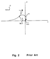
- Figure 2 shows a graphical representation of this transition mode, where H(0) represents the initial center 13 of the tip of momentum vector 7 in the X-Z plane nutating along an initial circular nutation path 15. From the example above, this graph can also be thought of as representing the view looking down on the nutating gyroscope along the momentum axis as momentum vector 7 traces the path of nutation.
- the spacecraft origin 11 formed by the intersection of the X (roll) and Z (yaw) axes including biases if desired, represents the desired momentum vector 7 position which, when achieved, will enable momentum wheel 3 to control spacecraft 1 stability during on-orbit mode operation.
- the present invention makes use of a compensated thruster 5 control system as well as a modified deadbeat sequence to more accurately and efficiently shift momentum vector 7 from any initial position to origin 11 in three thruster 5 firings.
- the modified deadbeat sequence is graphically illustrated in FIG. 3.
- spacecraft 1 nutation is represented by a momentum vector 7 tracing an initial nutation path 15 within the X-Z plane about an initial center of momentum 13.
- the first pulsing in this modified sequence occurs anywhere on this path after a fixed filter stabilization period in the control logic.
- thrusters 5 are pulsed for the exact duration necessary to eliminate most of the nutation and move the center of momentum from initial center 13 to approximately the first firing point 17.
- This first pulsing serves two purposes: first, momentum vector 7 is moved closer to the origin; second, the nutation is minimized, linearizing the dynamic system, and thus allowing more accurate calculation of the final deadbeat pulse firings remaining to create the remaining origin-intercept vectors.
- the 2nd pulse width calculation is allowed several seconds to stabilize, before a second firing initiates the nutational trajectory 20.
- the second firing causes the center of momentum to shift from first firing point 17 to the center of momentum 22 along the nutational trajectory 20, which is designed to intersect origin 11 in one-half of the nutation period.
- a final third pulse is delivered at the origin 11 to bring the nutation to a halt at a point where momentum wheel 3 control is possible. Additional firings should not be necessary, since dynamic nonlinearities were minimized by the first firing and the finest resolution of sensing and actuating has already been achieved.
- Figure 4 shows a time-sequenced flow diagram of the disclosed transition mode.
- spacecraft 1 enters a transition mode 27 in which nutational motion is damped in preparation for on-orbit mode 43.
- the first step of the transition mode is a first wait period 29 in which the calculated pulse widths are allowed to reach a steady state. This first wait 29 nominally takes between 6 and 10 seconds.
- the first pulse 31 is then fired, transferring nutation path 15 to the first transient nutation path 20.
- a second wait 33 of 6 to 10 seconds is interjected to allow the calculated pulse widths to stabilize. In a sequence, the second pulse is fired, with more accurate pulse widths calculation, transferring the nutation path to a circular transient nutation path 204.
- a third wait 37 of one-half of a nutation period is required to allow the nutation path to intercept origin 11, at which time a third pulse 39 is fired, killing the nutational movement and stopping momentum vector 7 at origin 11.
- a fourth wait 41 of approximately one second is introduced to allow thruster 5 transients to settle. Conversion to an operational on-orbit mode 43 automatically follows the successful damping and spacecraft 1 orientation transition.
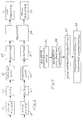
- Figure 5 shows the prior art transition control system which also forms the basis for thruster 5 compensation improvement of the present invention.
- error calculator 55 receives information relating to roll/yaw rates and yaw position from Digital Integrating Rate Assembly (DIRA) 51 and information relating to spacecraft 1 roll position from earth sensor 53.
- Error calculator 55 produces a pair of error coefficients which are ultimately used to determine thruster 5 pulse duration times for yaw and roll thrusters 71,73, respectively.
- Error calculator 55 produces yaw momentum error 57 and roll momentum error 59 and transmits these coefficients into a pair of low pass noise filters 61,63.
- DIRA Digital Integrating Rate Assembly
- noise filters 61,63 are multiplied by weighting factors 65,67 consisting of inertia components (I) divided by torque components (T). These coefficients are then quantized and advanced to thruster control timer 69 and used to control yaw and roll thrusters 71,73.
- a feedback network is present by way of spacecraft dynamics 75.
- the compensated thruster control system of the present invention is shown in FIG. 6.
- error coefficients are filtered in noise filters 61,63.
- the outputs of noise filters 61, 63 are then applied respectively to inertial and torque weighting factors in blocks 65 and 67.
- These are applied to thruster compensators 81, 83, wherein empirical information relating to the non-idealities of the averaged thruster's 5 performance is applied to the error coefficients.
- These coefficients are quantized in blocks 85,87, and these new error coefficients are implemented in a modified timing sequencer 89.
- This modified timing sequencer calculates and transmits firing durations in yaw and roll thrusters 71, 73, respectively.
- n represents the order of the polynomial function L(EPW).
- the value of n is chosen large enough to produce a close approximation of the emperical thruster 5 performance. Values between 3 and 6 are typical in the preferred embodiment of the present invention.
- this Loss function mathematically describes the thruster 5 non-idealities experienced at short firing durations, typically less than 40 msec.
- the object of the thruster 5 compensation is to generate a corresponding compensation function C which, when multiplied by the Loss equation, L(EPW), cancels the effects of the thruster 5 non-idealities.
- the equation is necessarily recursive since, in the region of non-ideality, the thruster 5 performance improves nonlinearly as pulsewidths increase.
- the compensation function implemented within the thruster 5 compensation block 81,83 can be expressed by the equation: where C(IPW) is in msec. Alternatively, piecewise linear segments can be used to approximate the polynomial in a numerically efficient method. In the preferred embodiment, IPW's of interest range from 2 msec. to 40 msec. Additional logic is provided to fix C at a constant value for IPW's less than 2 msec. and for IPW's greater than 40 msec.
- Figure 7 shows a flow chart for the method used in calculating the compensated thruster 5 coefficients.
- Block 91 refers to the generation of thruster 5 loss data based on empirical information taken from the individual thruster motors. This empirical data includes thruster 5 impulse as a function of burn time. This thruster 5 loss data is then used to create a derating model from which polynomial loss function coefficients can be generated as shown in step 93. The loss function coefficients are then used to solve a polynomial compensation function in step 95, from which compensation coefficients can be extracted. Alternatively the coefficients can be implemented in spacecraft as a piece-wise linear functions before quantization.
Abstract
Description
- This application incorporates by reference subject matter contained in U.S. Patent Number 4,931,942 issued to Garg et al. on June 5, 1990.
- This invention relates to a method of damping nutational motion in satellites and other spacecraft systems, and more particularly to providing a smooth transition from a station-keeping mode in which the spacecraft is under thruster control to an on-orbit operational status in which control is maintained using momentum wheels to make small orientational corrections.
- The improvements described in this disclosure incorporate by reference the subject matter described in U.S. Patent No. 4,931,942 issued to Garg et al. on June 5, 1990. The Garg patent describes a method for controlling nutational motion during spacecraft transition from a station-keeping mode to an on-orbit mode using a feedback control system to control multiple thruster pulse firings. Although the problems of thruster non-idealities and orbital dynamic nonlinearities were raised, no solutions were offered beyond convergence to stability through successive feedback controlled thruster pulses.
- U.S. Patent No. 4,289,051 issued to Goschel relates to the stabilizing of a satellite relative to the three major axes prior to the point in time when the satellite is to change orbits, whereupon the engine system for reaching the new orbit is switched on. No separate nutation-damping scheme is disclosed.
- U.S. Patent No. 4,537,375 issued to Chan describes a method of pre-biasing individual thruster motors to compensate for motor offsets and mismatches. The damping of nutational motion is not addressed.
- U.S. Patent No. 4,725,024 issued to Vorlicek describes a method for spinning-up a three-axis controlled spacecraft. Nutational motion compensation is not described.
- U.S. Patent No. 4,759,957 issued to Hubert et al. discloses a method for simultaneously processing and nutation-damping a spinning spacecraft that includes thruster firing in response to feedback from angular momentum gyros. This patent has no disclosure of the subject three-pulse thruster firing scheme, nor does it address the topic of thruster compensation.
- Other patents uncovered which contain additional information on the general topics of nutation, attenuation, correction in spacecraft systems and the like are as follows:
U.S. Patent No. Inventor 3,624,367 Hamilton, et al. 3,643,897 Johnson, Jr. 3,866,025 Cavanagh 3,937,423 Johansen 3,944,172 Becker 3,984,071 Fleming 3,997,137 Phillips 4,023,752 Pistiner, et al. 4,174,819 Bruederle, et al. 4,370,716 Armieux 4,386,750 Hoffman 4,521,855 Lehner, et al. - In accordance with the present invention, a method is provided for eliminating nutation in a three-axis stabilized spacecraft (1) employing internal momentum wheels (3) as an attitude stabilizer. Nutation damping is effected using a closed loop control system in which the momentum wheels (3) work in conjunction with spacecraft thrusters (5). This invention discloses two advancements over the prior art. The first advancement is the addition of a thruster compensation mechanism (81,83) to the conventional transition mode control system. The second improvement is the incorporation of a modified deadbeat thruster timing sequence, in which the nutating spacecraft (1) is brought under on-orbit control within three pulses of the thrusters (5).
- The thruster compensation mechanism (81,83) comprises a method of correcting thruster (5) inefficiencies which occur in extremely short duration firings, often used in attitude control. During short pulsing periods, fuel is inadequately mixed in the combustion chamber, resulting in power loss. The method consists of equating empirical data on thruster (5) inefficiencies to a polynomial expression and using this polynomial to compensate the error correction coefficients in the solution of the control system equations.
- The second advancement presented is the disclosure of a modified thruster (5) sequence for stopping nutation and orienting the spacecraft (1) for on-orbit operation. The prior art teaches that a deadbeat sequence of two pulses is theoretically sufficient for transition from the station-keeping mode to on-orbit operation. In practice, nonlinearities of the dynamic system and non-idealities in the control mechanism require three or more pulsings for complete transition within the requirements of on-orbit operation. Using the three thruster (5) firing technique disclosed below, a first pulse (31) is used to minimize nonlinear spacecraft dynamics and to permit orientation using two additional adjustment pulses (35,39) which act as a deadbeat sequence.
-
- Figure 1 is a schematic representation of a prior art satellite orbiting in a three-dimensional vector space;
- Figure 2 is a diagram showing the prior art damping of the momentum vector in the X-Z plane by deadbeat impulse firing of a three-axis stabilized satellite;
- Figure 3 is a diagram showing the damping of transverse momentum of the present invention by deadbeat impulse firing of a three-axis stabilized
spacecraft 1; - Figure 4 is a flow diagram showing the modified thruster sequence steps of the present invention;
- Figure 5 is a schematic diagram of the prior art nutational damping control system;
- Figure 6 is a schematic diagram of the thruster compensation and sequencing section of the nutational damping control system of the present invention; and
- Figure 7 is a flow diagram showing the thruster loss compensation algorithm of the present invention.
- Figure 1 illustrates a conventional orbiting
satellite 1. Under normal on-orbit operation, attitude control is maintained through one or more spinningmomentum wheels 3. Eachmomentum wheel 3 is rigidly attached toframe 2 of thesatellite 1 and provides inertial stability, represented by aperpendicular momentum vector 7, which in the example shown in FIG. 1, points along the -Y 7 direction. Small changes insatellite 1 orientation can be effected by changing the speed of one ormore momentum wheels 3 and thereby redirectingmomentum vector 7. - Periodically,
satellite 1 is commanded into a station-keeping mode in order to adjust the orbit or trajectory of operation. This station-keeping mode is implemented using one ormore thrusters 5 which fire for a set duration to adjust the orbit ofsatellite 1. A byproduct of the station-keeping mode is the introduction of various attitudinal perturbations produced by thethruster 5 forces. Among these disturbances is the tendency ofsatellite 1 to develop a nutational motion about its pitch or Y-axis 6. This nutational motion can be understood by imagining the application of a momentary perpendicular force to the rotational axis of a spinning top or gyroscope. The perpendicular force will cause the top to begin to nutate around the axis of its new momentum vector. The satellite's nutation preventsmomentum wheel 3 from controlling the attitude, since the momentum of the nutation greatly exceeds the momentum capability ofcontrol wheel 3. - The goal of the transition mode correction sequence is to utilize short pulses of
thruster 5 creating impulses to stop the nutation and to orientmomentum vector 7 in a desired direction, such that attitudinal control bymomentum wheel 3 can be resumed. Figure 2 shows a graphical representation of this transition mode, where H(0) represents theinitial center 13 of the tip ofmomentum vector 7 in the X-Z plane nutating along an initialcircular nutation path 15. From the example above, this graph can also be thought of as representing the view looking down on the nutating gyroscope along the momentum axis asmomentum vector 7 traces the path of nutation. Thespacecraft origin 11, formed by the intersection of the X (roll) and Z (yaw) axes including biases if desired, represents the desiredmomentum vector 7 position which, when achieved, will enablemomentum wheel 3 to controlspacecraft 1 stability during on-orbit mode operation. - The prior art teaches that in the ideal system, deadbeat nutation damping allows the initial center of
momentum 13 to be moved toorigin 11 in two pulses ofthrusters 5 from any arbitrary initial condition. The first pulse is triggered as thespacecraft 1 nutates topoint 17. This first firing creates anutational trajectory 20 ofmomentum vector 7 which will cross theorigin 11. At the point of intersection of the X and Z axes,thrusters 5 are fired a second time to stopmomentum vector 7 atorigin 11. At this point, the nutational component is eliminated andmomentum vector 7 will be controllable by themomentum wheels 3. U.S. Patent 4,931,942 teaches additional firings near theorigin 11 to compensate for non-idealities which may prevent exact intersection withorigin 11. - The present invention makes use of a compensated
thruster 5 control system as well as a modified deadbeat sequence to more accurately and efficiently shiftmomentum vector 7 from any initial position toorigin 11 in threethruster 5 firings. The modified deadbeat sequence is graphically illustrated in FIG. 3. As in the prior art diagram of FIG. 2,spacecraft 1 nutation is represented by amomentum vector 7 tracing aninitial nutation path 15 within the X-Z plane about an initial center ofmomentum 13. After the mode is initiated by ground command, the first pulsing in this modified sequence occurs anywhere on this path after a fixed filter stabilization period in the control logic. At thisfiring point thrusters 5 are pulsed for the exact duration necessary to eliminate most of the nutation and move the center of momentum frominitial center 13 to approximately thefirst firing point 17. This first pulsing serves two purposes: first,momentum vector 7 is moved closer to the origin; second, the nutation is minimized, linearizing the dynamic system, and thus allowing more accurate calculation of the final deadbeat pulse firings remaining to create the remaining origin-intercept vectors. - Following the first firing, the 2nd pulse width calculation is allowed several seconds to stabilize, before a second firing initiates the
nutational trajectory 20. The second firing causes the center of momentum to shift fromfirst firing point 17 to the center ofmomentum 22 along thenutational trajectory 20, which is designed to intersectorigin 11 in one-half of the nutation period. A final third pulse is delivered at theorigin 11 to bring the nutation to a halt at a point wheremomentum wheel 3 control is possible. Additional firings should not be necessary, since dynamic nonlinearities were minimized by the first firing and the finest resolution of sensing and actuating has already been achieved. - Figure 4 shows a time-sequenced flow diagram of the disclosed transition mode. Following the completion of station-keeping
mode 25,spacecraft 1 enters atransition mode 27 in which nutational motion is damped in preparation for on-orbit mode 43. The first step of the transition mode is afirst wait period 29 in which the calculated pulse widths are allowed to reach a steady state. Thisfirst wait 29 nominally takes between 6 and 10 seconds. Thefirst pulse 31 is then fired, transferringnutation path 15 to the firsttransient nutation path 20. Asecond wait 33 of 6 to 10 seconds is interjected to allow the calculated pulse widths to stabilize. In a sequence, the second pulse is fired, with more accurate pulse widths calculation, transferring the nutation path to a circular transient nutation path 204. Athird wait 37 of one-half of a nutation period is required to allow the nutation path to interceptorigin 11, at which time athird pulse 39 is fired, killing the nutational movement and stoppingmomentum vector 7 atorigin 11. Afourth wait 41 of approximately one second is introduced to allowthruster 5 transients to settle. Conversion to an operational on-orbit mode 43 automatically follows the successful damping andspacecraft 1 orientation transition. - Figure 5 shows the prior art transition control system which also forms the basis for
thruster 5 compensation improvement of the present invention. At the completion of the station-keeping maneuver, error calculator 55 receives information relating to roll/yaw rates and yaw position from Digital Integrating Rate Assembly (DIRA) 51 and information relating tospacecraft 1 roll position fromearth sensor 53. Error calculator 55 produces a pair of error coefficients which are ultimately used to determinethruster 5 pulse duration times for yaw and rollthrusters yaw momentum error 57 and rollmomentum error 59 and transmits these coefficients into a pair of low pass noise filters 61,63. The outputs of noise filters 61,63 are multiplied byweighting factors 65,67 consisting of inertia components (I) divided by torque components (T). These coefficients are then quantized and advanced tothruster control timer 69 and used to control yaw and rollthrusters spacecraft dynamics 75. - The compensated thruster control system of the present invention is shown in FIG. 6. As in the prior art, error coefficients are filtered in noise filters 61,63. The outputs of noise filters 61, 63 are then applied respectively to inertial and torque weighting factors in
blocks 65 and 67. These are applied tothruster compensators 81, 83, wherein empirical information relating to the non-idealities of the averaged thruster's 5 performance is applied to the error coefficients. These coefficients are quantized inblocks timing sequencer 89. This modified timing sequencer calculates and transmits firing durations in yaw and rollthrusters - Prior to installing
thrusters 5 on thespacecraft 1, experimental burn data is collected by operatingthrusters 5 over a range of burn durations, while recordingthruster 5 impulse as a function of duration. In the preferred embodiment of the present invention data for burn periods of between 0 and 64 msec. is generally collected. This empirical data is used to derive a polynomial approximation of the form where L(EPW)
represents the Loss (L≦1) or efficiency of thethruster 5 as a function of the electrical pulsewidth in msec. - The positive, non-zero, integer n represents the order of the polynomial function L(EPW). The value of n is chosen large enough to produce a close approximation of the
emperical thruster 5 performance. Values between 3 and 6 are typical in the preferred embodiment of the present invention. - As discussed above this Loss function mathematically describes the
thruster 5 non-idealities experienced at short firing durations, typically less than 40 msec. The object of thethruster 5 compensation is to generate a corresponding compensation function C which, when multiplied by the Loss equation, L(EPW), cancels the effects of thethruster 5 non-idealities. Such a function C of the Idealized Pulsewidth (IPW) can be found by applying the Loss coefficients L₁, ...Ln to solve for a set of corresponding compensation coefficients C₁, ...Cn using the relationship:

where

The equation is necessarily recursive since, in the region of non-ideality, thethruster 5 performance improves nonlinearly as pulsewidths increase. The compensation function implemented within thethruster 5compensation block 81,83 can be expressed by the equation:
where C(IPW) is in msec. Alternatively, piecewise linear segments can be used to approximate the polynomial in a numerically efficient method. In the preferred embodiment, IPW's of interest range from 2 msec. to 40 msec. Additional logic is provided to fix C at a constant value for IPW's less than 2 msec. and for IPW's greater than 40 msec. - Figure 7 shows a flow chart for the method used in calculating the compensated
thruster 5 coefficients.Block 91 refers to the generation ofthruster 5 loss data based on empirical information taken from the individual thruster motors. This empirical data includesthruster 5 impulse as a function of burn time. Thisthruster 5 loss data is then used to create a derating model from which polynomial loss function coefficients can be generated as shown instep 93. The loss function coefficients are then used to solve a polynomial compensation function instep 95, from which compensation coefficients can be extracted. Alternatively the coefficients can be implemented in spacecraft as a piece-wise linear functions before quantization. The quantization function applied byblock

- The invention has now been explained with reference to specific embodiments. Other embodiments will be apparent to those of ordinary skill in the art in light of this disclosure. Therefore it is not intended that this invention be limited, except as indicated by the appended claims.
Claims (5)
- A method for compensating thruster losses in a nutational damping control system, wherein the method comprises the steps:
generating empirical loss data for at least one thruster;
characterizing the thruster loss data by a polynomial equation of the form:
solving extended pulsewidth times from the recursive equation:

where

and C(IPW) is the compensation function of the idealized pulsewidth (IPW);
quantizing the extended pulsewidth times using the function:

applying the quantized extended pulsewidths to thrusters by incorporation into the nutational damping control system. - The method in claim 1, wherein the step for generating empirical thruster loss data comprises the substeps:
operating the thrusters over a range of burn durations; and
recording thruster impulse as a function of burn duration. - The method in claim 2, wherein the range of burn durations extends from 0 to 64 msec.
- A method for damping nutation in a spacecraft having a control system comprising thrusters and noise filters, by using a modified deadbeat thruster firing sequence, wherein the method comprises the steps:
firing a first thruster pulse to linearize spacecraft motion;
computing direction and duration of a second thruster pulse firing;
allowing the momentum error filter to reach steady state through a short wait period;
firing the second thruster pulse in order to nutate the spacecraft to an origin point of desired on-orbit operation;
waiting one-half of a nutation period as the spacecraft nutates to the origin; and
firing a third thruster pulse to stop nutation when the spacecraft reaches the origin. - The method in claim 4, wherein the firing of the first thruster pulse is preceeded by a short wait period for allowing the calculated coefficients to reach steady state.
Applications Claiming Priority (2)
| Application Number | Priority Date | Filing Date | Title |
|---|---|---|---|
| US07/679,655 US5222023A (en) | 1991-04-02 | 1991-04-02 | Compensated transition for spacecraft attitude control |
| US679655 | 1991-04-02 |
Publications (2)
| Publication Number | Publication Date |
|---|---|
| EP0507460A1 true EP0507460A1 (en) | 1992-10-07 |
| EP0507460B1 EP0507460B1 (en) | 1995-05-17 |
Family
ID=24727796
Family Applications (1)
| Application Number | Title | Priority Date | Filing Date |
|---|---|---|---|
| EP92302068A Expired - Lifetime EP0507460B1 (en) | 1991-04-02 | 1992-03-11 | Compensated transition for spacecraft attitude control |
Country Status (5)
| Country | Link |
|---|---|
| US (1) | US5222023A (en) |
| EP (1) | EP0507460B1 (en) |
| JP (1) | JP2623402B2 (en) |
| CA (1) | CA2062308C (en) |
| DE (1) | DE69202507T2 (en) |
Cited By (1)
| Publication number | Priority date | Publication date | Assignee | Title |
|---|---|---|---|---|
| EP0752366A1 (en) * | 1995-07-03 | 1997-01-08 | Space Systems / Loral, Inc. | Post transition momentum management |
Families Citing this family (24)
| Publication number | Priority date | Publication date | Assignee | Title |
|---|---|---|---|---|
| WO1992003339A1 (en) * | 1990-08-22 | 1992-03-05 | Microcosm, Inc. | Satellite orbit maintenance system |
| US5687084A (en) * | 1992-05-26 | 1997-11-11 | Microcosm, Inc. | Satellite orbit maintenance system |
| US5395076A (en) * | 1993-03-19 | 1995-03-07 | Martin Marietta Corporation | Spacecraft velocity change maneuvers by variable arcjets |
| US5459669A (en) * | 1994-02-14 | 1995-10-17 | Space Systems/Loral, Inc. | Control system and method for spacecraft attitude control |
| US6068217A (en) * | 1996-10-16 | 2000-05-30 | Space Systems/Loral, Inc. | Method to reorient a spacecraft using only initial single axis attitude knowledge |
| US6000661A (en) * | 1996-10-16 | 1999-12-14 | Space Systems/Loral, Inc. | Autonomous spacecraft payload base motion estimation and correction |
| US5996942A (en) * | 1996-10-16 | 1999-12-07 | Space Systems/Loral, Inc. | Autonomous solar torque management |
| US6023291A (en) * | 1996-10-16 | 2000-02-08 | Space Systems/Loral, Inc. | Satellite camera attitude determination and image navigation by means of earth edge and landmark measurement |
| WO1998032657A1 (en) | 1997-01-27 | 1998-07-30 | Space Systems/Loral, Inc. | Spacecraft attitude control system using low thrust thrusters |
| US5957411A (en) | 1997-01-31 | 1999-09-28 | Space Systems/Loral, Inc. | Method using double thruster firings to deadbeat flexible solar array structural oscillations |
| US6108593A (en) * | 1997-07-09 | 2000-08-22 | Hughes Electronics Corporation | Method and apparatus for estimating attitude sensor bias in a satellite |
| DE60032681T2 (en) * | 1999-08-13 | 2007-10-18 | Hughes Electronics Corp., El Segundo | Orbit control of a spacecraft upon feedback of the position of the orbit |
| ES2180367B1 (en) * | 2000-03-01 | 2004-04-01 | Centro De Investigacion De Tecnicas Aeroespaciales, S.A. (Cenita) | NEW PROCEDURE TO MODIFY THE TRAJECTORY OF A MOBILE OR PARTICULAR BODY. |
| US6340138B1 (en) * | 2000-05-08 | 2002-01-22 | Hughes Electronics Corporation | Stationkeeping method utilizing open-loop thruster pulses and closed-loop authority limited momentum storage devices |
| ES2171355B1 (en) * | 2000-10-10 | 2003-12-01 | Cenita S A | A SYSTEM AND A METHOD FOR MODIFYING AND CONTROLLING ENGINEER TRAVELS IN SPACES OR AIR NAVIGATION, AND TO MODIFY INERT BODY PATHWAYS THAT TRAVEL THROUGH SPACE. |
| DE10342866A1 (en) * | 2003-09-15 | 2005-04-21 | Eads Astrium Gmbh | Method for determining the position of a spacecraft with the aid of a direction vector and a total twist measurement |
| US6921049B2 (en) * | 2003-11-18 | 2005-07-26 | The Boeing Company | System for counteracting a disturbance in a spacecraft |
| US7437222B2 (en) * | 2005-07-28 | 2008-10-14 | The Boeing Company | Gimbal disturbance calibration and compenstion |
| KR100837138B1 (en) | 2006-07-18 | 2008-06-11 | 한국과학기술원 | Method for Dynamic Control Allocation to Shape Spacecraft Attitude Control Command |
| US8019493B1 (en) * | 2007-07-20 | 2011-09-13 | Lockheed Martin Corporation | Spacecraft thruster torque feedforward calibration system |
| US8763957B1 (en) * | 2012-10-08 | 2014-07-01 | Space Systems/Loral, Llc | Spacecraft transfer orbit techniques |
| US10501211B1 (en) * | 2015-12-17 | 2019-12-10 | Space Systems/Loral, Llc | Pre and post orbit maneuver pulses to reduce flexural oscillations |
| CN109649689B (en) * | 2018-12-07 | 2021-10-01 | 北京空间飞行器总体设计部 | Limited thrust orbital transfer gravity loss calculation method and thrust calculation device |
| CN113060306B (en) * | 2021-03-31 | 2022-02-08 | 中国空气动力研究与发展中心设备设计与测试技术研究所 | Multi-pulse intersection iterative guidance method and device for limited thrust and electronic equipment |
Citations (4)
| Publication number | Priority date | Publication date | Assignee | Title |
|---|---|---|---|---|
| EP0119810A2 (en) * | 1983-03-12 | 1984-09-26 | British Aerospace Public Limited Company | Nutation damping |
| US4504032A (en) * | 1982-03-10 | 1985-03-12 | Rca Corporation | Control of nutation in a spacecraft |
| EP0341130A1 (en) * | 1988-04-26 | 1989-11-08 | AEROSPATIALE Société Nationale Industrielle | Method for slewing the inertial moment of a spinning body in space up to a given direction |
| EP0347585A1 (en) * | 1988-05-26 | 1989-12-27 | Space Systems / Loral, Inc. | Transition control system for spacecraft attitude control |
Family Cites Families (17)
| Publication number | Priority date | Publication date | Assignee | Title |
|---|---|---|---|---|
| US3643897A (en) * | 1968-10-18 | 1972-02-22 | Communications Satellite Corp | Nutation correction system for spin-stabilized satellite |
| US3624367A (en) * | 1968-11-12 | 1971-11-30 | Gen Electric | Self-optimized and adaptive attitude control system |
| US3866025A (en) * | 1972-03-17 | 1975-02-11 | Rca Corp | Spacecraft attitude control system |
| US3944172A (en) * | 1972-04-14 | 1976-03-16 | Erno Raumfahrttechnik Gmbh | Attitude control for space vehicle |
| US4023752A (en) * | 1973-12-10 | 1977-05-17 | Rca Corporation | Elimination of residual spacecraft nutation due to propulsive torques |
| US3997137A (en) * | 1973-12-10 | 1976-12-14 | Rca Corporation | Minimization of residual spacecraft nutation due to disturbing torques |
| US3937423A (en) * | 1974-01-25 | 1976-02-10 | Hughes Aircraft Company | Nutation and roll error angle correction means |
| US3984071A (en) * | 1974-08-29 | 1976-10-05 | Trw Inc. | Satellite nutation attenuation apparatus |
| DE2642061C2 (en) * | 1976-09-18 | 1983-11-24 | Messerschmitt-Bölkow-Blohm GmbH, 8000 München | Position control and orbit change method for a three-axis stabilizable satellite, in particular for a geostationary satellite and device for carrying out the method |
| DE2732201C2 (en) * | 1977-07-16 | 1983-01-13 | Messerschmitt-Bölkow-Blohm GmbH, 8000 München | Regulator for the attitude stabilization of a satellite |
| FR2447320A1 (en) * | 1979-01-23 | 1980-08-22 | Matra | IMPROVEMENTS TO ACTIVE NUTATION DAMPING METHODS AND DEVICES FOR SPATIAL VEHICLE |
| US4386750A (en) * | 1980-08-29 | 1983-06-07 | The United States Of America As Represented By The Administrator Of The National Aeronautics And Space Administration | Method of damping nutation motion with minimum spin axis attitude disturbance |
| US4521855A (en) * | 1981-07-27 | 1985-06-04 | Ford Aerospace & Communications Corporation | Electronic on-orbit roll/yaw satellite control |
| US4537375A (en) * | 1983-04-21 | 1985-08-27 | Ford Aerospace & Communications Corporation | Method and apparatus for thruster transient control |
| US4758957A (en) * | 1985-05-17 | 1988-07-19 | General Electric Company | Spacecraft stabilization system and method |
| US4725024A (en) * | 1985-11-15 | 1988-02-16 | Ford Aerospace & Communications Corporation | Method for spinning up a three-axis controlled spacecraft |
| US5098041A (en) * | 1990-06-07 | 1992-03-24 | Hughes Aircraft Company | Attitude control system for momentum-biased spacecraft |
-
1991
- 1991-04-02 US US07/679,655 patent/US5222023A/en not_active Expired - Fee Related
-
1992
- 1992-03-04 CA CA002062308A patent/CA2062308C/en not_active Expired - Fee Related
- 1992-03-11 EP EP92302068A patent/EP0507460B1/en not_active Expired - Lifetime
- 1992-03-11 DE DE69202507T patent/DE69202507T2/en not_active Expired - Fee Related
- 1992-04-02 JP JP4108387A patent/JP2623402B2/en not_active Expired - Lifetime
Patent Citations (4)
| Publication number | Priority date | Publication date | Assignee | Title |
|---|---|---|---|---|
| US4504032A (en) * | 1982-03-10 | 1985-03-12 | Rca Corporation | Control of nutation in a spacecraft |
| EP0119810A2 (en) * | 1983-03-12 | 1984-09-26 | British Aerospace Public Limited Company | Nutation damping |
| EP0341130A1 (en) * | 1988-04-26 | 1989-11-08 | AEROSPATIALE Société Nationale Industrielle | Method for slewing the inertial moment of a spinning body in space up to a given direction |
| EP0347585A1 (en) * | 1988-05-26 | 1989-12-27 | Space Systems / Loral, Inc. | Transition control system for spacecraft attitude control |
Non-Patent Citations (2)
| Title |
|---|
| JOURNAL OF GUIDANCE AND CONTROL. vol. 3, no. 4, August 1980, NEW YORK US pages 361 - 368; YUAN, C.S.: 'DEADBEAT NUTATION CONTROLLER FOR MOMENTUM BIAS STABILIZED SPACECRAFT' * |
| PROCEEDINGS OF THE 1989 AMERICAN CONTROL CONFERENCE vol. 3, 23 June 1989, PITTSBURGH (USA) pages 2263 - 2268; EKE,F.O. ET AL.: 'BACKUP NUTATION DAMPING STRATEGY FOR THE GALILEO SPACECRAFT' * |
Cited By (2)
| Publication number | Priority date | Publication date | Assignee | Title |
|---|---|---|---|---|
| EP0752366A1 (en) * | 1995-07-03 | 1997-01-08 | Space Systems / Loral, Inc. | Post transition momentum management |
| US5655735A (en) * | 1995-07-03 | 1997-08-12 | Space Systems Loral, Inc. | Post transition momentum management |
Also Published As
| Publication number | Publication date |
|---|---|
| CA2062308C (en) | 1999-08-03 |
| EP0507460B1 (en) | 1995-05-17 |
| DE69202507T2 (en) | 1996-02-01 |
| JP2623402B2 (en) | 1997-06-25 |
| JPH06135396A (en) | 1994-05-17 |
| US5222023A (en) | 1993-06-22 |
| DE69202507D1 (en) | 1995-06-22 |
| CA2062308A1 (en) | 1992-10-03 |
Similar Documents
| Publication | Publication Date | Title |
|---|---|---|
| EP0507460B1 (en) | Compensated transition for spacecraft attitude control | |
| EP0769736B1 (en) | Method for inclined orbit attitude control for momentum bias spacecraft | |
| US4567564A (en) | Arrangement for the attitude stabilization of flexible vehicles with weakly-dampened structural vibrations and discontinuous control intervention | |
| US5459669A (en) | Control system and method for spacecraft attitude control | |
| US7988097B2 (en) | Precision attitude control system for gimbaled thruster | |
| US5535965A (en) | Three-axis stabilized, earth-oriented satellite and a corresponding sun and earth acquisition process | |
| EP0568209B1 (en) | Spacecraft attitude control and momentum unloading using gimballed and throttled thrusters | |
| US5149022A (en) | Satellite roll and yaw attitude control method | |
| EP0225683B1 (en) | Method for spinning up a three-axis controlled spacecraft | |
| US6296207B1 (en) | Combined stationkeeping and momentum management | |
| CA2041857C (en) | Attitude control system for momentum-biased spacecraft | |
| WO2002057136A1 (en) | Gimbaled thruster control system | |
| EP0251692A2 (en) | Orbit control system for a satellite | |
| EP0861784A2 (en) | Spacecraft attitude control apparatus and method | |
| US5984237A (en) | Delta-V targeting system for three-axis controlled spacecraft | |
| US6347262B1 (en) | Minimum fuel attitude and nutation controller for spinning spacecraft | |
| JP2002046697A (en) | Correcting method for argument of perigee with longitude control for satellite orbiting in inclined elliptic geosynchronous orbit | |
| EP1103464A2 (en) | Spacecraft and appendage stepping methods that improve spacecraft attitude pointing and cancel solar array slew disturbances | |
| Coon et al. | Skylab attitude control system | |
| JP3174174B2 (en) | Satellite attitude control system | |
| EP0544241A1 (en) | Method and apparatus for dynamic precompensation of solar wing stepping motions of a satellite | |
| EP1059577B1 (en) | Time delay compensation for spacecraft motion compensation | |
| Spencer | Automatic magnetic control of a momentum-biased observatory in equatorial orbit | |
| LEE et al. | Space station RCS attitude control system | |
| McEwen | Overview of the Miniature Sensor Technology Integration (MSTI) spacecraft attitude control system |
Legal Events
| Date | Code | Title | Description |
|---|---|---|---|
| PUAI | Public reference made under article 153(3) epc to a published international application that has entered the european phase |
Free format text: ORIGINAL CODE: 0009012 |
|
| AK | Designated contracting states |
Kind code of ref document: A1 Designated state(s): DE FR GB IT |
|
| 17P | Request for examination filed |
Effective date: 19921106 |
|
| 17Q | First examination report despatched |
Effective date: 19940121 |
|
| GRAA | (expected) grant |
Free format text: ORIGINAL CODE: 0009210 |
|
| AK | Designated contracting states |
Kind code of ref document: B1 Designated state(s): DE FR GB IT |
|
| ITF | It: translation for a ep patent filed |
Owner name: JACOBACCI & PERANI S.P.A. |
|
| REF | Corresponds to: |
Ref document number: 69202507 Country of ref document: DE Date of ref document: 19950622 |
|
| ET | Fr: translation filed | ||
| PLBE | No opposition filed within time limit |
Free format text: ORIGINAL CODE: 0009261 |
|
| STAA | Information on the status of an ep patent application or granted ep patent |
Free format text: STATUS: NO OPPOSITION FILED WITHIN TIME LIMIT |
|
| 26N | No opposition filed | ||
| REG | Reference to a national code |
Ref country code: GB Ref legal event code: IF02 |
|
| PGFP | Annual fee paid to national office [announced via postgrant information from national office to epo] |
Ref country code: FR Payment date: 20020221 Year of fee payment: 11 |
|
| PGFP | Annual fee paid to national office [announced via postgrant information from national office to epo] |
Ref country code: GB Payment date: 20020306 Year of fee payment: 11 |
|
| PGFP | Annual fee paid to national office [announced via postgrant information from national office to epo] |
Ref country code: DE Payment date: 20020320 Year of fee payment: 11 |
|
| PG25 | Lapsed in a contracting state [announced via postgrant information from national office to epo] |
Ref country code: GB Free format text: LAPSE BECAUSE OF NON-PAYMENT OF DUE FEES Effective date: 20030311 |
|
| PG25 | Lapsed in a contracting state [announced via postgrant information from national office to epo] |
Ref country code: DE Free format text: LAPSE BECAUSE OF NON-PAYMENT OF DUE FEES Effective date: 20031001 |
|
| GBPC | Gb: european patent ceased through non-payment of renewal fee |
Effective date: 20030311 |
|
| PG25 | Lapsed in a contracting state [announced via postgrant information from national office to epo] |
Ref country code: FR Free format text: LAPSE BECAUSE OF NON-PAYMENT OF DUE FEES Effective date: 20031127 |
|
| REG | Reference to a national code |
Ref country code: FR Ref legal event code: ST |
|
| PG25 | Lapsed in a contracting state [announced via postgrant information from national office to epo] |
Ref country code: IT Free format text: LAPSE BECAUSE OF NON-PAYMENT OF DUE FEES;WARNING: LAPSES OF ITALIAN PATENTS WITH EFFECTIVE DATE BEFORE 2007 MAY HAVE OCCURRED AT ANY TIME BEFORE 2007. THE CORRECT EFFECTIVE DATE MAY BE DIFFERENT FROM THE ONE RECORDED. Effective date: 20050311 |