EP0514044B1 - Cord Retainer - Google Patents
Cord Retainer Download PDFInfo
- Publication number
- EP0514044B1 EP0514044B1 EP92303910A EP92303910A EP0514044B1 EP 0514044 B1 EP0514044 B1 EP 0514044B1 EP 92303910 A EP92303910 A EP 92303910A EP 92303910 A EP92303910 A EP 92303910A EP 0514044 B1 EP0514044 B1 EP 0514044B1
- Authority
- EP
- European Patent Office
- Prior art keywords
- locking means
- wing members
- tube
- cylindrical tube
- cord retainer
- Prior art date
- Legal status (The legal status is an assumption and is not a legal conclusion. Google has not performed a legal analysis and makes no representation as to the accuracy of the status listed.)
- Expired - Lifetime
Links
Images


Classifications
-
- F—MECHANICAL ENGINEERING; LIGHTING; HEATING; WEAPONS; BLASTING
- F16—ENGINEERING ELEMENTS AND UNITS; GENERAL MEASURES FOR PRODUCING AND MAINTAINING EFFECTIVE FUNCTIONING OF MACHINES OR INSTALLATIONS; THERMAL INSULATION IN GENERAL
- F16G—BELTS, CABLES, OR ROPES, PREDOMINANTLY USED FOR DRIVING PURPOSES; CHAINS; FITTINGS PREDOMINANTLY USED THEREFOR
- F16G11/00—Means for fastening cables or ropes to one another or to other objects; Caps or sleeves for fixing on cables or ropes
- F16G11/10—Quick-acting fastenings; Clamps holding in one direction only
- F16G11/101—Quick-acting fastenings; Clamps holding in one direction only deforming the cable by moving a part of the fastener
-
- A—HUMAN NECESSITIES
- A44—HABERDASHERY; JEWELLERY
- A44B—BUTTONS, PINS, BUCKLES, SLIDE FASTENERS, OR THE LIKE
- A44B99/00—Subject matter not provided for in other groups of this subclass
-
- Y—GENERAL TAGGING OF NEW TECHNOLOGICAL DEVELOPMENTS; GENERAL TAGGING OF CROSS-SECTIONAL TECHNOLOGIES SPANNING OVER SEVERAL SECTIONS OF THE IPC; TECHNICAL SUBJECTS COVERED BY FORMER USPC CROSS-REFERENCE ART COLLECTIONS [XRACs] AND DIGESTS
- Y10—TECHNICAL SUBJECTS COVERED BY FORMER USPC
- Y10T—TECHNICAL SUBJECTS COVERED BY FORMER US CLASSIFICATION
- Y10T24/00—Buckles, buttons, clasps, etc.
- Y10T24/39—Cord and rope holders
- Y10T24/3969—Sliding part or wedge
-
- Y—GENERAL TAGGING OF NEW TECHNOLOGICAL DEVELOPMENTS; GENERAL TAGGING OF CROSS-SECTIONAL TECHNOLOGIES SPANNING OVER SEVERAL SECTIONS OF THE IPC; TECHNICAL SUBJECTS COVERED BY FORMER USPC CROSS-REFERENCE ART COLLECTIONS [XRACs] AND DIGESTS
- Y10—TECHNICAL SUBJECTS COVERED BY FORMER USPC
- Y10T—TECHNICAL SUBJECTS COVERED BY FORMER US CLASSIFICATION
- Y10T24/00—Buckles, buttons, clasps, etc.
- Y10T24/39—Cord and rope holders
- Y10T24/3984—Alignable aperture and spring pressed moving element
-
- Y—GENERAL TAGGING OF NEW TECHNOLOGICAL DEVELOPMENTS; GENERAL TAGGING OF CROSS-SECTIONAL TECHNOLOGIES SPANNING OVER SEVERAL SECTIONS OF THE IPC; TECHNICAL SUBJECTS COVERED BY FORMER USPC CROSS-REFERENCE ART COLLECTIONS [XRACs] AND DIGESTS
- Y10—TECHNICAL SUBJECTS COVERED BY FORMER USPC
- Y10T—TECHNICAL SUBJECTS COVERED BY FORMER US CLASSIFICATION
- Y10T403/00—Joints and connections
- Y10T403/57—Distinct end coupler
- Y10T403/5733—Plural opposed sockets
Definitions
- This invention relates to a retainer assembly for retaining in position cords or strings that fasten jackets, sports wear, hoods, shoes and the like.
- a typical prior example comprises a tubular body having registering holes adjacent to opposite ends, a pair of end taps having corresponding holes and adapted to fixedly close the respective ends of the body and a compression spring interposed therebetween, the arrangement being that the taps are brought toward each other axially of the tubular body against the tension of the compression spring until the holes in the tubular body register with the holes in the end taps.
- This type of retainer is disclosed for example in Japanese Laid-Open Utility Model Publications Nos. 57-203809, 63-52412 and 63-117308. The retainer is split into halves, one of which is assembled with the compression spring and one end tap and thereafter joined with the other half portion.
- engaging means provided in the inner surface of the tubular body and in the outer surface of the respective taps are joined together by rotating the taps relative to the tubular body. This assembling procedure is literally tedious and time-consuming.
- FIG. 2-28609 Another prior art device is shown in Japanese Laid-Open Utility Model Publication No. 2-28609 in which there is provided a cord retainer having a tubular body with a centrally located hole, an outer sleeve fixedly connected to one end of the tubular body and an inner sleeve movable within the outer sleeve, the two sleeves having respective holes registrable with the central hole in the tubular body against the tension of a compression coil spring interposed between the sleeves. Assembly of this cord retainer is likewise complex, involving increased numbers of component parts and hence higher cost.
- EP-A-289358 (the embodiment according to figures 1 to 10 inclusive) upon which the preamble of claim 1 is based, discloses a cord retainer which comprises:
- the locking means is integral with the tube and there is only one pair of diametrically aligned holes in the tube and only one end tap.
- the present invention seeks to provide a cord retainer which is relatively simple in construction with few component parts and highly reliable in operation.
- the present invention provides a cord retainer as claimed in claim 1, to which reference is directed.
- the retainer 10 for retaining cords, strings or the like against unintentional displacement relative to an article to which they are attached.
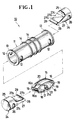
- the retainer 10 herein comprehensively referred to as a cord retainer, comprises a cylindrical tube 11 forming a retainer body which is provided with a pair of elongate or otherwise round holes 12, 12 registering with each other diammetrically across the tube 11 adjacent to one end thereof, and a similar pair of aligned holes 12, 12 adjacent to the opposite end of the tube 11 for receiving a cord C ( Figure 5) or the like.
- the cylindrical tube 11 has annular flanges 13, 13 at the respective ends and a plurality (three in the illustrated embodiment) of annular rims 14 spaced around its central periphery for purposes later described.
- a resilient locking means which comprises a pair of upper and lower wing members 16, 16 interconnected centrally in spaced-apart relation by a connecting post 17 which provides on opposite sides thereof two identical chambers 18, 18 and which extends substantially diammetrically across the interior of tube 11 when the retainer 10 is assembled as shown in Figure 3.
- the upper and lower wing members 16, 16 are bent arcuately inwardly about the connecting post 17 with their respective inwardly directed end flanges 16a, 16a held in closely confronting relation to define therebetween a small gap or slit 19 communicating with corresponding chamber 18 at each of their opposite ends.
- An arcuate rib 20 is formed on the outer surface of each of the upper and lower wing members 16, 16 and extends centrally longitudinally thereof as better shown in Figure 1.
- the connecting post 17 has a pair of lugs 21, 21 projecting laterally from opposite ends thereof and each having a recess 21a.
- the resilient locking means 15 thus constructed is assembled into the cylindrical tube 11, in which instance the arcuate ribs 20, 20 are inserted in diammetrically opposed engaging grooves 22, 22 formed axially in the inner wall of the tube 11, and the recesses 21a, 21a of the lugs 21, 21 are held in receptive engagement with diammetrically opposed pins 23, 23 projecting inwardly from the inner wall of the tube 11 at an angular distance of substantially 90° apart from the engaging grooves 22, 22 as better shown in Figure 2.
- the use of lugs 21, 21 with recesses 21a, 21a for engagement with the pins 23, 23 can be disposed with, if arrangements are made such that the arcuate ribs 20, 20 are clamped under pressure into firm gripping engagement with the engaging grooves 22, 22.
- Each end tap 24 has a barrel portion 25 substantially round in cross section and slightly smaller in diameter than the inside diameter of the cylindrical tube 11 so that the end tap 24 can move within and through the tube 11 in a manner later described.
- the tap 24 has a through bore 26 extending diammetrically across the barrel portion 25 and registrable with the holes 12, 12 of the cylindrical tube 11.
- the tap 24 includes a tapered connecting portion 27 with opposite surfaces 27a, 27a thereof progressively converging from the barrel portion 25 toward a cross-sectionally arrow-headed anchoring portion 28 disposed remotely from the barrel portion 25.
- the anchoring portion 28 has vertical abutments 29 bordering with a reduced terminal end 27b of the tapered connecting portion 27 opposite to a thicker end 27c thereof merging with the barrel portion 25.
- the resilient locking means 15 When assembling the cord retainer 10, the resilient locking means 15 is inserted into and fixed in place within the cylindrical tube 11 in the manner above described, followed by mounting the pair of end taps 24, 24 from opposite ends of the tube 11, in which instance the barrel portion 25 of each tap is pushed axially inward through the tubular body 11 of the retainer 10 until the arrow-headed anchoring portion 28 passes through the slit 19 of the locking means 15 into the chamber 18, urging the slit 19 to spread open against the tension between the upper and lower wing members 16, 16.
- each tap 24 to retract outwardly under the influence of tension exerted by the wing members 16, 16 with the arrow-headed portion 28 snapped in place (with its vertical abutments 29 borne against the inner walls of the end flanges 16a, 16a of the wing members 16, 16), as shown in Figure 3.
- the end taps 24, 24 are released so that the taps 24, 24 are urged to retract or move outwardly away from each other by the tension or closing force of the locking means 15, whereupon the through bores 26, 26 in the respective end taps 24, 24 become displaced with respect to their associated holes 12, 12 in the cylindrical tube 11, leaving the cord C immovably trapped in the retainer 10 as shown in Figure 5.
Description
- This invention relates to a retainer assembly for retaining in position cords or strings that fasten jackets, sports wear, hoods, shoes and the like.
- Retainers or stoppers for such cords or strings have been proposed in different form and construction. A typical prior example comprises a tubular body having registering holes adjacent to opposite ends, a pair of end taps having corresponding holes and adapted to fixedly close the respective ends of the body and a compression spring interposed therebetween, the arrangement being that the taps are brought toward each other axially of the tubular body against the tension of the compression spring until the holes in the tubular body register with the holes in the end taps. This type of retainer is disclosed for example in Japanese Laid-Open Utility Model Publications Nos. 57-203809, 63-52412 and 63-117308. The retainer is split into halves, one of which is assembled with the compression spring and one end tap and thereafter joined with the other half portion. Alternatively, engaging means provided in the inner surface of the tubular body and in the outer surface of the respective taps are joined together by rotating the taps relative to the tubular body. This assembling procedure is literally tedious and time-consuming.
- Another prior art device is shown in Japanese Laid-Open Utility Model Publication No. 2-28609 in which there is provided a cord retainer having a tubular body with a centrally located hole, an outer sleeve fixedly connected to one end of the tubular body and an inner sleeve movable within the outer sleeve, the two sleeves having respective holes registrable with the central hole in the tubular body against the tension of a compression coil spring interposed between the sleeves. Assembly of this cord retainer is likewise complex, involving increased numbers of component parts and hence higher cost.
- EP-A-289358 (the embodiment according to figures 1 to 10 inclusive) upon which the preamble of claim 1 is based, discloses a cord retainer which comprises:
- (i) a cylindrical tube having opposite ends and having a pair of diametrically aligned holes at one of said ends;
- (ii) a resilient locking means having opposite ends, being fixedly mounted in said cylindrical tube and having upper and lower wing members interconnected in spaced-apart relation to provide a chamber, said wing members each having an inwardly directed end flange and each being bent arcuately inwardly, from where said wing members are interconnected towards said end flanges, with said end flanges held in closely confronting relation to define a slit at one of said ends of said locking means; and
- (iii) an end tap having a through bore registrable with said holes of said cylindrical tube and having an arrow-headed portion projecting through said slit for anchoring engagement with said locking means;
said tube being formed as a first component part;
said end tap being formed as a second component part separately from said tube. - However, in the embodiment according to figures 1 to 10 inclusive of EP-A-289358, the locking means is integral with the tube and there is only one pair of diametrically aligned holes in the tube and only one end tap.
- In the embodiment according to figures 1 to 10 inclusive of EP-A-289358, due to the fact that the locking means is integral with the tube, the upper and lower wings would be prevented from spreading apart sufficiently upon depression of the end tap into the tube, if the user were accidentally to grip the front and back of the tube tightly.
- With the foregoing drawbacks of the prior art in view, the present invention seeks to provide a cord retainer which is relatively simple in construction with few component parts and highly reliable in operation.
- The present invention provides a cord retainer as claimed in claim 1, to which reference is directed.
- The above and other advantages and features of the invention will be better understood from the following detailed description of a preferred embodiment, taken in conjunction with the accompanying drawings.
- Figure 1 is an exploded perspective view of an embodiment of a cord retainer provided in accordance with the present invention;
- Figure 2 is a radial cross-sectional view of a portion of the cord retainer of Figure 1;
- Figure 3 is an axial cross-sectional view of the cord retainer shown assembled;
- Figure 4 is a view similar to Figure 3 but showing the cord retainer in one operative position; and
- Figure 5 is a view similar to Figure 4 but showing the cord retainer in another operative position.
- Referring now to the drawings and Figure 1 in particular, there is shown a
retainer 10 for retaining cords, strings or the like against unintentional displacement relative to an article to which they are attached. Theretainer 10, herein comprehensively referred to as a cord retainer, comprises acylindrical tube 11 forming a retainer body which is provided with a pair of elongate or otherwiseround holes tube 11 adjacent to one end thereof, and a similar pair of alignedholes tube 11 for receiving a cord C (Figure 5) or the like. Thecylindrical tube 11 hasannular flanges annular rims 14 spaced around its central periphery for purposes later described. - Designated generally at 15 is a resilient locking means which comprises a pair of upper and
lower wing members post 17 which provides on opposite sides thereof twoidentical chambers tube 11 when theretainer 10 is assembled as shown in Figure 3. The upper andlower wing members post 17 with their respective inwardly directedend flanges corresponding chamber 18 at each of their opposite ends. Anarcuate rib 20 is formed on the outer surface of each of the upper andlower wing members post 17 has a pair oflugs recess 21a. - The resilient locking means 15 thus constructed is assembled into the
cylindrical tube 11, in which instance thearcuate ribs engaging grooves tube 11, and therecesses lugs pins tube 11 at an angular distance of substantially 90° apart from theengaging grooves lugs recesses pins arcuate ribs engaging grooves - Designated generally at 24, 24 are a pair of end taps for closing respective open ends of the
cylindrical tube 11. Eachend tap 24 has abarrel portion 25 substantially round in cross section and slightly smaller in diameter than the inside diameter of thecylindrical tube 11 so that theend tap 24 can move within and through thetube 11 in a manner later described. Thetap 24 has athrough bore 26 extending diammetrically across thebarrel portion 25 and registrable with theholes cylindrical tube 11. Thetap 24 includes a tapered connectingportion 27 withopposite surfaces barrel portion 25 toward a cross-sectionally arrow-headed anchoring portion 28 disposed remotely from thebarrel portion 25. The anchoringportion 28 hasvertical abutments 29 bordering with a reducedterminal end 27b of the tapered connectingportion 27 opposite to athicker end 27c thereof merging with thebarrel portion 25. - When assembling the
cord retainer 10, the resilient locking means 15 is inserted into and fixed in place within thecylindrical tube 11 in the manner above described, followed by mounting the pair ofend taps tube 11, in which instance thebarrel portion 25 of each tap is pushed axially inward through thetubular body 11 of theretainer 10 until the arrow-headed anchoringportion 28 passes through theslit 19 of the locking means 15 into thechamber 18, urging theslit 19 to spread open against the tension between the upper andlower wing members barrel portion 25 causes eachtap 24 to retract outwardly under the influence of tension exerted by thewing members portion 28 snapped in place (with itsvertical abutments 29 borne against the inner walls of theend flanges wing members 16, 16), as shown in Figure 3. - Now when applying the cord C to the
cord retainer 10, the twoend taps headed anchoring portion 28 is brought into abutting engagement with thelug 21 of the locking means 15, in which position the throughbore 26 in thebarrel portion 25 of each end tap 24 registers with the corresponding alignedholes cylindrical tube 11 as shown in Figure 4. After the cord C is passed through the thus registeredholes end taps taps bores respective end taps holes cylindrical tube 11, leaving the cord C immovably trapped in theretainer 10 as shown in Figure 5. - Manipulation of the
end taps annular flanges 13 and theannular rims 14 which can be gripped with the fingers of the user while moving the end taps 24, 24 axially inwardly of thecylindrical tube 11 against the tension of the locking means 15.
Claims (4)
- A cord retainer (10) which comprises:(i) a cylindrical tube (11) having opposite ends and having a pair of diametrically aligned holes (12, 12) at one of said ends;(ii) a resilient locking means (15) having opposite ends, being fixedly mounted in said cylindrical tube (11) and having upper and lower wing members (16, 16) interconnected in spaced-apart relation to provide a chamber (18), said wing members (16, 16) each having an inwardly directed end flange (16a) and each being bent arcuately inwardly, from where said wing members (16, 16) are interconnected towards said end flanges (16a, 16a), with said end flanges (16a, 16a) held in closely confronting relation to define a slit (19) at one of said ends of said locking means (15); and(iii) an end tap (24) having a through bore (26) registrable with said holes (12) of said cylindrical tube (11) and having an arrow-headed portion (28) projecting through said slit (19) for anchoring engagement with said locking means (15);
said tube (11) being formed as a first component part;
said end tap (24) being formed as a second component part separately from said tube (11); characterised in that:(iv) said tube (11) has a second pair of diametrically aligned holes (12, 12) at the end opposite said one end;(v) said upper and lower wing members (16, 16) are interconnected in spaced-apart relation by a connecting post (17) centrally of said wing members (16, 16) so as to provide a second chamber (18), said wing members (16, 16) each having a second inwardly directed end flange (16a) and each being bent arcuately inwardly, from where said wing members (16, 16) are interconnected towards said second end flanges (16a, 16a), with said second end flanges (16a, 16a) held in closely confronting relation to define a second slit (19) at the end opposite said one end of said locking means (15); and(iii) a second end tap (24) having a second through bore (26) registrable with said second pair of holes (12) of said cylindrical tube (11) and having a second arrow-headed portion (28) projecting through said second slit (19) for anchoring engagement with said locking means (15);
said second end tap (24) being formed as a third component part separately from said first and second component parts;
said locking means (15) being formed as a fourth component part separately from said first, second and third component parts. - A cord retainer (10) according to claim 1 characterized in that said cylindrical tube (11) has a plurality of annular rims (14) spaced around its periphery.
- A cord retainer (10) according to claim 1 or 2 characterized in that all of its component parts are made of a plastics material.
- A cord retainer (10) according to claim 1, 2 or 3 characterized in that said end taps (24, 24) each have a tapered connecting portion (27) with opposite surfaces (27a, 27a) thereof progressively converging toward said arrow-headed portion (28).
Applications Claiming Priority (2)
| Application Number | Priority Date | Filing Date | Title |
|---|---|---|---|
| JP1991040142U JP2561565Y2 (en) | 1991-05-01 | 1991-05-01 | Cord stopper |
| JP40142/91 | 1991-05-01 |
Publications (3)
| Publication Number | Publication Date |
|---|---|
| EP0514044A2 EP0514044A2 (en) | 1992-11-19 |
| EP0514044A3 EP0514044A3 (en) | 1992-11-25 |
| EP0514044B1 true EP0514044B1 (en) | 1995-12-27 |
Family
ID=12572529
Family Applications (1)
| Application Number | Title | Priority Date | Filing Date |
|---|---|---|---|
| EP92303910A Expired - Lifetime EP0514044B1 (en) | 1991-05-01 | 1992-04-30 | Cord Retainer |
Country Status (5)
| Country | Link |
|---|---|
| US (1) | US5224245A (en) |
| EP (1) | EP0514044B1 (en) |
| JP (1) | JP2561565Y2 (en) |
| KR (1) | KR940001555Y1 (en) |
| DE (1) | DE69207064T2 (en) |
Families Citing this family (15)
| Publication number | Priority date | Publication date | Assignee | Title |
|---|---|---|---|---|
| JPH0534907U (en) * | 1991-10-17 | 1993-05-14 | 吉田工業株式会社 | Cord stopper |
| JPH0593224U (en) * | 1992-05-20 | 1993-12-21 | 吉田工業株式会社 | Tie |
| US5711032A (en) * | 1994-08-09 | 1998-01-27 | Carpenter; Jake | Locking apparatus for a draw cord |
| JP3254095B2 (en) * | 1995-02-28 | 2002-02-04 | ワイケイケイ株式会社 | String anchor |
| US5967151A (en) * | 1996-01-18 | 1999-10-19 | Beadwear, Inc. | Hair bead stop and method of beading hair |
| US5924178A (en) * | 1998-04-17 | 1999-07-20 | Lazylock Ab | Tightening device for shoelaces and like elongated and pliable elements having free ends |
| IT243966Y1 (en) * | 1998-04-27 | 2002-03-06 | System Plast Snc Marsetti & C | TIGHTENING DEVICE FOR AT LEAST ONE PIN SUPPORT OF BELT CONVEYOR COMPONENTS |
| US5961062A (en) * | 1998-05-21 | 1999-10-05 | Beihl; Amanda Herbst | Retaining cords |
| US6016813A (en) * | 1998-09-04 | 2000-01-25 | Beadwear, Inc. | Bead lock and method of retaining beads |
| US6711785B1 (en) * | 1999-06-04 | 2004-03-30 | Bryan K. Hicks | Lanyard connector and system |
| US20090025616A1 (en) * | 2007-07-23 | 2009-01-29 | Amsafe, Inc. | Air cargo pallets having synthetic cores and associated systems and methods for manufacturing same |
| US20100031477A1 (en) * | 2008-08-05 | 2010-02-11 | Charles Lamar Harrison | Adjustable retainer |
| TW201100031A (en) * | 2009-06-16 | 2011-01-01 | kun-zhong Liu | Shoelace length adjustment device |
| JP5687850B2 (en) * | 2010-06-02 | 2015-03-25 | 株式会社ニフコ | Code lock |
| USD751400S1 (en) * | 2014-04-25 | 2016-03-15 | Designetics, Inc. | Receptacle for inverted containers |
Family Cites Families (15)
| Publication number | Priority date | Publication date | Assignee | Title |
|---|---|---|---|---|
| GB549947A (en) * | 1941-11-14 | 1942-12-15 | Fullerton George Gordon Armstr | Improvements in or relating to rapid releasable couplings |
| US3080867A (en) * | 1958-05-22 | 1963-03-12 | Eichinger Maximilian | Clamping device |
| JPS55101205A (en) * | 1979-01-30 | 1980-08-01 | Yoshihiko Ishiguro | String camping tool |
| GB2066891B (en) * | 1980-01-03 | 1983-07-27 | Oppenheim M J | Cord securing device |
| US4393550A (en) * | 1981-04-20 | 1983-07-19 | James Yang | Safety clasp for the string of footwear |
| JPS57203809A (en) * | 1981-06-09 | 1982-12-14 | Yamaha Motor Co Ltd | Pressure reducing device at starting of engine with cranking starter |
| SE443909B (en) * | 1982-12-16 | 1986-03-17 | Fixfabriken Ab | cord lock |
| US4506417A (en) * | 1983-05-06 | 1985-03-26 | Nifco Inc. | Fastener for string |
| US4622723A (en) * | 1985-03-18 | 1986-11-18 | American Cord & Webbing Co., Inc. | Cord lock |
| JPS6352412A (en) * | 1986-08-22 | 1988-03-05 | Hitachi Ltd | Etching method for thin film |
| JPH053052Y2 (en) * | 1986-09-26 | 1993-01-26 | ||
| JP2618380B2 (en) * | 1986-11-06 | 1997-06-11 | キヤノン電子 株式会社 | Magnetoresistive head and method of manufacturing the same |
| JPH053053Y2 (en) * | 1987-01-23 | 1993-01-26 | ||
| JPH0540731Y2 (en) * | 1987-05-01 | 1993-10-15 | ||
| JPH0228609U (en) * | 1988-08-18 | 1990-02-23 |
-
1991
- 1991-05-01 JP JP1991040142U patent/JP2561565Y2/en not_active Expired - Fee Related
-
1992
- 1992-04-30 KR KR9207319U patent/KR940001555Y1/en not_active IP Right Cessation
- 1992-04-30 EP EP92303910A patent/EP0514044B1/en not_active Expired - Lifetime
- 1992-04-30 DE DE69207064T patent/DE69207064T2/en not_active Expired - Fee Related
- 1992-05-01 US US07/877,227 patent/US5224245A/en not_active Expired - Fee Related
Also Published As
| Publication number | Publication date |
|---|---|
| DE69207064T2 (en) | 1996-08-22 |
| JP2561565Y2 (en) | 1998-01-28 |
| EP0514044A3 (en) | 1992-11-25 |
| EP0514044A2 (en) | 1992-11-19 |
| JPH04125709U (en) | 1992-11-17 |
| KR920020703U (en) | 1992-12-18 |
| KR940001555Y1 (en) | 1994-03-19 |
| DE69207064D1 (en) | 1996-02-08 |
| US5224245A (en) | 1993-07-06 |
Similar Documents
| Publication | Publication Date | Title |
|---|---|---|
| EP0514044B1 (en) | Cord Retainer | |
| US5634244A (en) | Clasp for beaded chains | |
| US5549407A (en) | Locking mechanism for telescoping tubular poles | |
| US6299397B1 (en) | Double ended expansion fastener | |
| US4178023A (en) | Couplings for tubes | |
| US5383259A (en) | Adjustable shock cord end | |
| US7195286B2 (en) | Tube joint | |
| US3633250A (en) | Mechanical connector system including bifurcate hinged connector means | |
| US6039303A (en) | High pressure fluidline connector | |
| US3995897A (en) | Coupling | |
| US20010024594A1 (en) | Locking mechanism for telescopically adjustable extension pole | |
| KR100712030B1 (en) | Instantaneous connection device | |
| JPH01320395A (en) | Hose coupling | |
| EP0173713A1 (en) | Hose clamp | |
| KR20150023276A (en) | Plug connection for fluid lines and holding part for such a plug connection | |
| EP1369632B1 (en) | Means for the connection of two pipes | |
| CA2172753A1 (en) | Quick connect/disconnect coupling | |
| EP0537974B1 (en) | Cord stopper | |
| CA1222784A (en) | Ferrule, coupling and coupling process | |
| US5216780A (en) | Handgrip for link chain | |
| US3205759A (en) | Two-piece molding fastener | |
| US5226769A (en) | Device for the assembly and the rapid disassembly of two parts, one on the other | |
| US5943923A (en) | Retaining device of socket spanner | |
| US4083587A (en) | Split-ring type pipe couplings | |
| US4108507A (en) | Through-wall cable support |
Legal Events
| Date | Code | Title | Description |
|---|---|---|---|
| PUAI | Public reference made under article 153(3) epc to a published international application that has entered the european phase |
Free format text: ORIGINAL CODE: 0009012 |
|
| PUAL | Search report despatched |
Free format text: ORIGINAL CODE: 0009013 |
|
| AK | Designated contracting states |
Kind code of ref document: A2 Designated state(s): DE FR GB IT |
|
| AK | Designated contracting states |
Kind code of ref document: A3 Designated state(s): DE FR GB IT |
|
| 17P | Request for examination filed |
Effective date: 19930212 |
|
| 17Q | First examination report despatched |
Effective date: 19940527 |
|
| RAP1 | Party data changed (applicant data changed or rights of an application transferred) |
Owner name: YKK CORPORATION |
|
| GRAA | (expected) grant |
Free format text: ORIGINAL CODE: 0009210 |
|
| AK | Designated contracting states |
Kind code of ref document: B1 Designated state(s): DE FR GB IT |
|
| ITF | It: translation for a ep patent filed |
Owner name: JACOBACCI & PERANI S.P.A. |
|
| REF | Corresponds to: |
Ref document number: 69207064 Country of ref document: DE Date of ref document: 19960208 |
|
| PGFP | Annual fee paid to national office [announced via postgrant information from national office to epo] |
Ref country code: FR Payment date: 19960328 Year of fee payment: 5 |
|
| ET | Fr: translation filed | ||
| PGFP | Annual fee paid to national office [announced via postgrant information from national office to epo] |
Ref country code: GB Payment date: 19960422 Year of fee payment: 5 |
|
| PGFP | Annual fee paid to national office [announced via postgrant information from national office to epo] |
Ref country code: DE Payment date: 19960531 Year of fee payment: 5 |
|
| PLBE | No opposition filed within time limit |
Free format text: ORIGINAL CODE: 0009261 |
|
| STAA | Information on the status of an ep patent application or granted ep patent |
Free format text: STATUS: NO OPPOSITION FILED WITHIN TIME LIMIT |
|
| 26N | No opposition filed | ||
| PG25 | Lapsed in a contracting state [announced via postgrant information from national office to epo] |
Ref country code: GB Effective date: 19970430 |
|
| GBPC | Gb: european patent ceased through non-payment of renewal fee |
Effective date: 19970430 |
|
| PG25 | Lapsed in a contracting state [announced via postgrant information from national office to epo] |
Ref country code: FR Free format text: LAPSE BECAUSE OF NON-PAYMENT OF DUE FEES Effective date: 19971231 |
|
| PG25 | Lapsed in a contracting state [announced via postgrant information from national office to epo] |
Ref country code: DE Free format text: LAPSE BECAUSE OF NON-PAYMENT OF DUE FEES Effective date: 19980101 |
|
| REG | Reference to a national code |
Ref country code: FR Ref legal event code: ST |
|
| PG25 | Lapsed in a contracting state [announced via postgrant information from national office to epo] |
Ref country code: IT Free format text: LAPSE BECAUSE OF NON-PAYMENT OF DUE FEES;WARNING: LAPSES OF ITALIAN PATENTS WITH EFFECTIVE DATE BEFORE 2007 MAY HAVE OCCURRED AT ANY TIME BEFORE 2007. THE CORRECT EFFECTIVE DATE MAY BE DIFFERENT FROM THE ONE RECORDED. Effective date: 20050430 |