EP0514114B1 - Optical fiber connector having enhanced provisions for interconnection and for prevention of optical and mechanical disconnection - Google Patents
Optical fiber connector having enhanced provisions for interconnection and for prevention of optical and mechanical disconnection Download PDFInfo
- Publication number
- EP0514114B1 EP0514114B1 EP92304238A EP92304238A EP0514114B1 EP 0514114 B1 EP0514114 B1 EP 0514114B1 EP 92304238 A EP92304238 A EP 92304238A EP 92304238 A EP92304238 A EP 92304238A EP 0514114 B1 EP0514114 B1 EP 0514114B1
- Authority
- EP
- European Patent Office
- Prior art keywords
- cap
- ferrule
- barrel
- connector
- optical fiber
- Prior art date
- Legal status (The legal status is an assumption and is not a legal conclusion. Google has not performed a legal analysis and makes no representation as to the accuracy of the status listed.)
- Expired - Lifetime
Links
Images


Classifications
-
- G—PHYSICS
- G02—OPTICS
- G02B—OPTICAL ELEMENTS, SYSTEMS OR APPARATUS
- G02B6/00—Light guides; Structural details of arrangements comprising light guides and other optical elements, e.g. couplings
- G02B6/24—Coupling light guides
- G02B6/36—Mechanical coupling means
- G02B6/38—Mechanical coupling means having fibre to fibre mating means
- G02B6/3807—Dismountable connectors, i.e. comprising plugs
- G02B6/389—Dismountable connectors, i.e. comprising plugs characterised by the method of fastening connecting plugs and sockets, e.g. screw- or nut-lock, snap-in, bayonet type
- G02B6/3893—Push-pull type, e.g. snap-in, push-on
-
- G—PHYSICS
- G02—OPTICS
- G02B—OPTICAL ELEMENTS, SYSTEMS OR APPARATUS
- G02B6/00—Light guides; Structural details of arrangements comprising light guides and other optical elements, e.g. couplings
- G02B6/24—Coupling light guides
- G02B6/36—Mechanical coupling means
- G02B6/38—Mechanical coupling means having fibre to fibre mating means
- G02B6/3807—Dismountable connectors, i.e. comprising plugs
- G02B6/381—Dismountable connectors, i.e. comprising plugs of the ferrule type, e.g. fibre ends embedded in ferrules, connecting a pair of fibres
- G02B6/3826—Dismountable connectors, i.e. comprising plugs of the ferrule type, e.g. fibre ends embedded in ferrules, connecting a pair of fibres characterised by form or shape
- G02B6/3831—Dismountable connectors, i.e. comprising plugs of the ferrule type, e.g. fibre ends embedded in ferrules, connecting a pair of fibres characterised by form or shape comprising a keying element on the plug or adapter, e.g. to forbid wrong connection
-
- G—PHYSICS
- G02—OPTICS
- G02B—OPTICAL ELEMENTS, SYSTEMS OR APPARATUS
- G02B6/00—Light guides; Structural details of arrangements comprising light guides and other optical elements, e.g. couplings
- G02B6/24—Coupling light guides
- G02B6/36—Mechanical coupling means
- G02B6/38—Mechanical coupling means having fibre to fibre mating means
- G02B6/3807—Dismountable connectors, i.e. comprising plugs
- G02B6/3833—Details of mounting fibres in ferrules; Assembly methods; Manufacture
- G02B6/3847—Details of mounting fibres in ferrules; Assembly methods; Manufacture with means preventing fibre end damage, e.g. recessed fibre surfaces
-
- G—PHYSICS
- G02—OPTICS
- G02B—OPTICAL ELEMENTS, SYSTEMS OR APPARATUS
- G02B6/00—Light guides; Structural details of arrangements comprising light guides and other optical elements, e.g. couplings
- G02B6/24—Coupling light guides
- G02B6/36—Mechanical coupling means
- G02B6/38—Mechanical coupling means having fibre to fibre mating means
- G02B6/3807—Dismountable connectors, i.e. comprising plugs
- G02B6/3869—Mounting ferrules to connector body, i.e. plugs
-
- G—PHYSICS
- G02—OPTICS
- G02B—OPTICAL ELEMENTS, SYSTEMS OR APPARATUS
- G02B6/00—Light guides; Structural details of arrangements comprising light guides and other optical elements, e.g. couplings
- G02B6/24—Coupling light guides
- G02B6/36—Mechanical coupling means
- G02B6/38—Mechanical coupling means having fibre to fibre mating means
- G02B6/3807—Dismountable connectors, i.e. comprising plugs
- G02B6/3873—Connectors using guide surfaces for aligning ferrule ends, e.g. tubes, sleeves, V-grooves, rods, pins, balls
- G02B6/3874—Connectors using guide surfaces for aligning ferrule ends, e.g. tubes, sleeves, V-grooves, rods, pins, balls using tubes, sleeves to align ferrules
- G02B6/3878—Connectors using guide surfaces for aligning ferrule ends, e.g. tubes, sleeves, V-grooves, rods, pins, balls using tubes, sleeves to align ferrules comprising a plurality of ferrules, branching and break-out means
-
- G—PHYSICS
- G02—OPTICS
- G02B—OPTICAL ELEMENTS, SYSTEMS OR APPARATUS
- G02B6/00—Light guides; Structural details of arrangements comprising light guides and other optical elements, e.g. couplings
- G02B6/24—Coupling light guides
- G02B6/36—Mechanical coupling means
- G02B6/38—Mechanical coupling means having fibre to fibre mating means
- G02B6/3807—Dismountable connectors, i.e. comprising plugs
- G02B6/3887—Anchoring optical cables to connector housings, e.g. strain relief features
- G02B6/3888—Protection from over-extension or over-compression
-
- G—PHYSICS
- G02—OPTICS
- G02B—OPTICAL ELEMENTS, SYSTEMS OR APPARATUS
- G02B6/00—Light guides; Structural details of arrangements comprising light guides and other optical elements, e.g. couplings
- G02B6/24—Coupling light guides
- G02B6/36—Mechanical coupling means
- G02B6/38—Mechanical coupling means having fibre to fibre mating means
- G02B6/3807—Dismountable connectors, i.e. comprising plugs
- G02B6/3897—Connectors fixed to housings, casing, frames or circuit boards
-
- G—PHYSICS
- G02—OPTICS
- G02B—OPTICAL ELEMENTS, SYSTEMS OR APPARATUS
- G02B6/00—Light guides; Structural details of arrangements comprising light guides and other optical elements, e.g. couplings
- G02B6/24—Coupling light guides
- G02B6/36—Mechanical coupling means
- G02B6/38—Mechanical coupling means having fibre to fibre mating means
- G02B6/3807—Dismountable connectors, i.e. comprising plugs
- G02B6/3833—Details of mounting fibres in ferrules; Assembly methods; Manufacture
- G02B6/3851—Ferrules having keying or coding means
-
- G—PHYSICS
- G02—OPTICS
- G02B—OPTICAL ELEMENTS, SYSTEMS OR APPARATUS
- G02B6/00—Light guides; Structural details of arrangements comprising light guides and other optical elements, e.g. couplings
- G02B6/24—Coupling light guides
- G02B6/36—Mechanical coupling means
- G02B6/38—Mechanical coupling means having fibre to fibre mating means
- G02B6/3807—Dismountable connectors, i.e. comprising plugs
- G02B6/3833—Details of mounting fibres in ferrules; Assembly methods; Manufacture
- G02B6/3854—Ferrules characterised by materials
-
- G—PHYSICS
- G02—OPTICS
- G02B—OPTICAL ELEMENTS, SYSTEMS OR APPARATUS
- G02B6/00—Light guides; Structural details of arrangements comprising light guides and other optical elements, e.g. couplings
- G02B6/24—Coupling light guides
- G02B6/36—Mechanical coupling means
- G02B6/38—Mechanical coupling means having fibre to fibre mating means
- G02B6/3807—Dismountable connectors, i.e. comprising plugs
- G02B6/3887—Anchoring optical cables to connector housings, e.g. strain relief features
- G02B6/38875—Protection from bending or twisting
Definitions
- This invention relates to an optical fiber connector which has enhanced provisions for interconnection and for the prevention of optical and mechanical disconnection.
- Connectors for optical fiber transmission systems are known in the art. Often times it becomes necessary to arrange a plurality of optical fiber connectors in a panel to facilitate multifiber connections.
- a very much used ferrule connector for terminating and connecting two optical fibers is one which is referred to as an ST® connector, ST being a registered trademark of AT&T.
- the ST connector is disclosed, for example, in U.S. patent 4,934,785.
- An ST connector includes a cylindrical plug or ferrule, as it is often called, having a passageway therethrough for receiving an end portion of an optical fiber to be terminated.
- the ferrule which is received in a barrel that is mounted in a cap is spring-loaded. When two of the ferrules are received end-to-end in a coupling sleeve, for example, one or both of the ferrules is moved along its longitudinal axis during the connection process.
- a key which extends radially from the barrel in which an end portion of the ferrule is received is aligned and moved along a keyway in a housing of a coupling as the ferrule is moved into a sleeve disposed within the housing.
- two locking pins which extend radially from the coupling housing are moved into and along camming slots which extend helically from a front end of the cap rearwardly. As the locking pins are moved along the camming slots, the ferrule is moved farther into the sleeve.
- each locking pin When each locking pin reaches an end of its associated camming slot, a craftsperson applies forces to the cap to cause it to move rotatably to cause each locking pin to be aligned with a relatively short locking slot which extends from an inner end of the associated camming slot toward a free end of the cap. This pushing motion followed by a rotary motion is often called a bayonet turn. Also, when each locking pin reaches an innermost end of the associated camming slot, the ferrule is at its farthest point within the sleeve from an entrance thereof.
- Stringent tolerances are needed in order to ensure that the overtravel and return of the ferrule to the optical connection plane are controlled to achieve a proper connection. It is most desirable that the connection be made without the need to bayonet turn or to turn threadably the connector cap as must be done with some presently manufactured ferrule connectors.
- the ferrule upon the application of forces to the cable in a direction transversely of the axis of the connector will result in a turning of the ferrule about a fulcrum located between the center of the sleeve and the end of the cap. This results in a canting of the end face of the ferrule and angular spacing thereof from the other ferrule or device thereby causing an optical disconnection or increased transmission loss.
- a non-optical disconnect feature is built into the connector plug arrangement. See U.S. patent 4,812,009.
- a cap extender extends longitudinally along the optical fiber cable and includes an externally threaded end which is turned into engagement with an internally threaded cable entrance end of the cap.
- the portion of the barrel which extends into the cap extender is provided with an annulus which when the cap extender is threaded completely into the cap engages an inner portion of the cap extender, restraining the barrel and the ferrule from movement.
- the cap extender is used to transfer transverse forces which are applied to the cable from the optical connection and instead transfers them to the connector cap.
- a conically shaped strain relief portion is disposed about and extends beyond the cap extender into engagement with the jacket of the cable.
- the sought after connector should be one which is assembled and secured to a coupling housing with linear motion only.
- an ST connector which is secured to a coupling housing, with the housing mounted in a panel by a pushing motion without the need to turn the connector relative to the housing, and yet is one which prevents decoupling of the ferrule and housing.
- an optical fiber connector as set forth in claim 1.
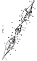
- FIGS. 1 and 2 there are shown perspective and side elevational views of a connector system designated generally by the numeral 20 which accommodates ferrule connectors that terminate optical fibers.
- a ferrule connector or plug assembly is depicted in FIGS. 1, 2 and 3 and is designated generally by the numeral 22.
- Each connector 22 includes a connector subassembly 25 and a shell 27.
- Each of two optical fibers 21 (see FIG. 3) to be connected includes a glass core and cladding, and a coating system, which is well known in the art.
- the optical fiber may be enclosed in a tube 28 of polyvinyl chloride (PVC) to provide what is referred to as a buffered fiber which may be terminated and connected in accordance with this invention.
- PVC polyvinyl chloride
- the connective arrangement of this invention also may be used to connect single fiber cables 30,30' (see again FIG. 1) in which covering the tube 28 is a strength member 29 such as one made of aramid fibrous material, for example, and an outer jacket 31 which may be comprised of PVC.
- the connector system 20 comprises two of the plug assemblies 22,22' which are connected through a coupling 35.
- Corresponding elements of the plug assemblies 22,22' are identified with the same numerals with those on the right as viewed in FIG. 2 being provided with a superscript prime.
- the plug assembly 22 is such that longitudinal axes 38,38' of the assemblies are coaxial.
- plug assemblies 22,22' are shown assembled to a coupling 35 mounted in a panel 37 with a lock washer 32 and a nut 34.
- each plug subassembly 25 comprises an optical fiber ferrule or plug 40, having a passageway 41 (see FIGS. 2 and 3) and being made of a glass, plastic or ceramic material, for example.
- the plug 40 has an outer diameter of about 2.5 mm.
- An end face 39 of the plug 40 includes an opening of the passageway 41.
- the optical fiber coating system, as well as the tube 28, the strength member 29 and the outer jacket 31, is removed from an end portion of an optical fiber 21 prior to its termination with a plug 40. Then the uncoated end portion of the optical fiber is inserted into the passageway 41 of a plug 40. The uncoated end portion of the optical fiber 21 is secured within the passageway 41 of the plug 40 and the end face of the optical fiber is cleaved and polished, for example. This process is repeated with another optical fiber and plug assembly.
- Each connector subassembly 25 also includes a connector body or barrel 42 (see FIGS. 1 and 2) made of a plastic or metallic material, a compression spring 44 and a tubular cap 45 (see also FIGS. 4 and 5) made of a plastic material. It should be observed that the plug 40, the barrel 42 and the cap 45 each has a cylindrical cross-section.
- the barrel 42 includes a separate orienting or alignment key 43 (see FIG. 6) which projects radially from the longitudinal axis 38. Also, an outer surface of the barrel is provided with a longitudinally extending slot 33.
- the barrel 42 includes an intermediate diameter portion 46 (see FIGS. 2 and 6) which extends through an opening 47 in an internally disposed annular lip 48 in the cap 45.
- a retaining washer 49 is disposed in a groove 50 (see FIGS. 3 and 6) and circumscribes the intermediate diameter portion on the outer side of the annular lip 48.
- the spring 44 is disposed about the intermediate diameter portion 46 of the barrel 42 between the annular lip 48 and a large diameter portion 51. As a result of this arrangement, the spring 44 biases the barrel 42 outwardly from the cable to hold the barrel within the cap 45.
- the cap 45 includes two diametrically opposed longitudinally extending slots 53,53' (see also FIGS. 7 and 8) each of which extends from a flanged beveled end 55 of the cap.
- the slot 53 is formed to include a tapered portion 56 which opens to an enlarged generally circular portion 57.
- the remaining portion of the slot 53 is considerably more narrow than the narrowest portion of the tapered portion 56 and terminates at an inner end 58.
- portions of a wall of the cap adjacent to each of the slots 53,53' are increased in thickness to provide a guide rail 59.
- the guide rail 59 is adapted to mate with portions of the shell 27 (see FIGS. 9-12).
- Each guide rail 59 is adapted to become received in an internally facing groove 52 (see FIG. 11 ) of the shell 27 to prevent rotation of the cap relative to the shell.
- the guide rail 59 reinforces the walls which define the associated slot 53.
- the cap 45 also includes a guide pin 61 (see FIG. 7).
- the guide pin 61 is adapted to be received in the longitudinally extending slot 33 (see FIG. 6) in the barrel to guide movement of the barrel relative to the cap 45 and to maintain one orientation of the key 43 relative to the slots 53,53' in the cap.
- an end 65 of the cap which is opposite to the flanged end 55 is threaded externally.
- the threaded portion facilitates securement of the cap to other portions of the connector and provides limits of travel for the shell 27.
- FIGS. 2, 3 and 13 a cap extender which is designated generally by the numeral 60 (see FIGS. 2, 3 and 13).
- the cap extender 60 includes an internally threaded opposite end 62 which is adapted to be secured to the externally threaded end of the cap 45.
- Projecting radially from the opposite end of the cap extender 60 is an annular detent 63.
- Connected to the internally threaded opposite end 62 is a smaller diameter portion 64 which is spaced a sufficient distance from the outer surface of the cable jacket 31 to provide an annular space 66 (see FIGS.
- the cap extender 60 includes provisions for limiting the distance by which the retainer washer 49 is allowed to move from the annular lip 48. This arrangement effectively limits rearward travel of the ferrule 40 which may be caused by inadvertent forces being applied to the cable 30. As a result, optical disconnection of fibers which are terminated by two ferrules is prevented. Optical disconnection is prevented by causing the cap extender to be provided with an annular shoulder 70.
- the shoulder 70 is disposed concentrically within, but spaced from, the externally threaded opposite end 62 of the cap extender 45. The diameter of the shoulder 70 is such that it engages the retaining washer 49 upon movement of the retaining washer to the left as viewed in FIG. 2.
- a cable support portion 75 (see FIG. 3) which may extend from the cap extender 60 along the optical fiber cable 30 in a conically shaped configuration.
- This portion of the plug assembly 22 provides cable strain relief and ensures that the cable can withstand repeated bends in use after interconnection with another cable without undue stresses being imparted to the optical fibers.
- the cable support portion includes two inwardly projecting ribs 76 and 77 which are received in grooves 78 and 79 of the cap extender 60.
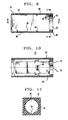
- the connector assembly 22 also includes the shell 27 (see FIGS. 2-3 and 9-12) and which is disposed about the cap 45, the cap extender 60 and the cable support portion 75.
- the shell 27 has a cross section transverse to the longitudinal axis of the connector which is square. Further, the shell 27 is formed to provide a chamber 81 which in cross section is substantially circular for receiving a connector subassembly comprising the cap extender, cap, barrel and ferrule.
- the shell 27 includes an end 82 which includes an inwardly projecting collar 84 and lateral shell portions 86,86' which may be flexed.
- a fulcrum 85 is associated with each portion 86.
- the shell portion 86 includes an externally knurled end portion 88.
- the shell portion 86 is provided with an inwardly facing latch 89 (see also FIG. 12) at each side.
- a shell 27 is caused to become disposed over a cap 45. Then a cap extender 60 is inserted into an opposite end of the shell and turned threadably onto the cap. Of course, a barrel 42, ferrule 40, a compression spring 44 and a retaining washer 49 are caused to become assembled to the cap.
- a connector assembly as is shown in FIG. 3 with the shell 27 being disposed in an unlocked position is moved toward a housing 90 (see FIGS. 1 and 14) of a coupling 35 which is mounted in the panel 37 to cause the ferrule 40 to enter a sleeve 92 which is mounted within the housing.
- the movement is made after the key 43 of the barrel 42 is aligned with a keyway 94 (see FIGS. 1 and 2) in the housing 90.
- pins 96,96' which project radially from the coupling housing are caused to enter the tapered slots 53,53' of the cap 45, the tapered slots 53,53' each being disposed at 90 ° to the key 43.
- each locking pin 96 is greater than the width of an inner portion of the slot 53, such movement causes the walls of the cap to be moved apart. Further movement of the connector assembly 22 causes each pin 96 of the coupling housing to become received in an enlarged opening 57 of the slot 53 (see FIG. 14) in which it is being moved to secure the cap to the coupling housing. As is noted, this assembly of the connector assembly 22 to the coupling housing 90 is accomplished with linear movement only of the assembly relative to the coupling housing.
- a free end of the ferrule 40 may abut a free end of another ferrule, a ferrule 40' which already is in the sleeve (see FIG. 2).
- spring forces cause the left-hand ferrule 40 as viewed in FIG. 2 to urge the other ferrule 40' to the right as viewed in FIG. 2, to a point of equilibrium of the two spring forces whereupon the free ends of the two ferrules are disposed in an optical connection plane 100.
- the end face 39 of the ferrule under the urging of its spring will become disposed to the right of the optical connection plane 100 with the barrel 42 engaging the coupling housing (see FIG. 14).
- each ferrule upon withdrawal of the other is capable of projecting outwardly from its associated cap a first distance X 1 until the enlarged portion 51 of the barrel 42 engages the coupling 35.
- any rearward movement of the ferrule 40 out of the sleeve such as by tensile forces applied to the cable must be limited to a distance less than the first distance X 1 to prevent optical disconnection. This is accomplished by limiting the distance between the retaining washer 49 and the cap extender shoulder 70 when the ferrule is disposed in the sleeve with its free end at the optical connection plane 100 to be a second distance X 2 (see FIG.
- each of cavities 97 and 98 (see FIG. 2) in ends of the coupling housing 90 is substantially the same when the housing is fitted with a sleeve retainer 102.
- Linear alignment of the barrel 42 and the ferrule 40 is maintained relative to the cap by the inwardly projecting guide pin 61 of the cap that is received in and that travels along the longitudinally extending slot 33 in the barrel.
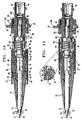
- the user moves the shell 27 slidably from its unlocked position as shown in FIG. 14 to its locked position shown in FIG. 15.
- the shell 27 is moved slidably toward the ferrule end of the connector assembly to cause the collar 84 to become engaged with the flanged end 55 of the cap.
- the detent 63 which is compressed as it is caused to move along the sidewall portion of the shell snap-locks into engagement with the latch 89 (see FIG. 15A) of the shell 27 to lock the cap 45 in position with the coupling housing pins 96,96' disposed in the portions 57,57' of the grooves 53,53' of the cap.
- Pushing the shell forward on the cap provides a mechanical lock and prevents unintentional mechanical decoupling of the connector plug assembly from the coupling housing 90 should the cable inadvertently be subjected to tensile forces.
- the shell has a cross sectional configuration transverse to a longitudinal axis which in a preferred embodiment is square.
- the inner portion of the shell in which is received the cap has a substantially circular cross section.
- the arrangement of this invention locks the shell 27 to the cap 45 and thereby prevents mechanical decoupling of the connector 22 from the coupling housing 90 when tensile or rotational forces are applied to a cable 30. Not only is mechanical decoupling prevented, but also the connector is such that optical disconnection from another connector in the sleeve 92 is prevented.
- Optical disconnection is prevented by the shoulder 70 of the cap extender 60 and its position relative to the retaining washer 49.
- FIG. 3 when the cap extender 60 is turned into the cap 45 and the ferrule 40 is disposed within the sleeve 92, a leading portion of the barrel is spaced from the housing 90. This occurs because with the ferrules 40,40' in engagement with each other at the optical plane in the sleeve 92, the ferrule 40, the ferrule on the left as viewed in FIG. 2, is not biased outwardly by the spring 44 as far as it would be if the associated ferrule was not engaging another ferrule (compare with FIG. 14).
- the retaining washer 49 is spaced from the annular lip 48 of the cap 45. Further, the retaining washer is spaced a distance X 2 from the shoulder 70. What is important is that the distance X 2 by which the ferrule 40 attached to the cable under tension, is less than the distance X 1 which the ferrule 40' can travel under the influence of its associated spring 44' can travel past the optical plane 100 to follow the ferrule 40 should the cable 30 be subjected to a tensile force substantially greater than two pounds. Therefore, when tensile forces are applied to the cable 30, the associated ferrule 40 is caused to move to the left as viewed in FIG. 2.
- the ferrule 40' follows the ferrule 40, remaining in engagement therewith. Then the retaining washer 49 of the ferrule 40 engages the shoulder 70 and because the distance X 1 which the ferrule 40' move is greater than X 2 , the may ferrule 40' is still in engagement with the ferrule 40, thereby preventing optical disconnection. Further movement of the ferrule 40 is prevented because of the engagement by the retaining washer 49 with the shoulder 70.
- the foregoing arrangement is effective when tensile forces are applied to only one cable 30 of a connective arrangement such as when a coupling is mounted in a panel 37 and forces are applied to a cable on one side of the panel. Optical disconnection may occur if tensile forces are applied simultaneously to both sides of the connection arrangement.
- a user depresses the flexible portions 86,86' of the shell adjacent to their knurled ends 88,88'. This causes the portions 86,86' to flex about their associated fulcrums 85,85' to disengage latches 89,89' from the detent 63 of the cap extender. This allows a pulling force which is applied to the cap to cause removal of the connector 22 from the coupling 35.
- the optical fiber connector 20 of this invention may be embodied in a duplex connector 110.
- the duplex connector 110 includes a shell 112 which is rectangular in cross section and which includes two cylindrical cavities each adapted to receive a connector plug subassembly 25. No special coupling or receptacle is required.
- Two connector subassemblies 25 are mounted side-by-side and assembled to two couplings 35 spaced apart a suitable distance.
- connectors which include more than two of the foregoing described connector subassemblies also may be provided.
Description
- This invention relates to an optical fiber connector which has enhanced provisions for interconnection and for the prevention of optical and mechanical disconnection.
- Connectors for optical fiber transmission systems are known in the art. Often times it becomes necessary to arrange a plurality of optical fiber connectors in a panel to facilitate multifiber connections. A very much used ferrule connector for terminating and connecting two optical fibers is one which is referred to as an ST® connector, ST being a registered trademark of AT&T. The ST connector is disclosed, for example, in U.S. patent 4,934,785.
- An ST connector includes a cylindrical plug or ferrule, as it is often called, having a passageway therethrough for receiving an end portion of an optical fiber to be terminated. The ferrule which is received in a barrel that is mounted in a cap is spring-loaded. When two of the ferrules are received end-to-end in a coupling sleeve, for example, one or both of the ferrules is moved along its longitudinal axis during the connection process.
- During the connection process, a key which extends radially from the barrel in which an end portion of the ferrule is received is aligned and moved along a keyway in a housing of a coupling as the ferrule is moved into a sleeve disposed within the housing. At the same time, two locking pins which extend radially from the coupling housing are moved into and along camming slots which extend helically from a front end of the cap rearwardly. As the locking pins are moved along the camming slots, the ferrule is moved farther into the sleeve. When each locking pin reaches an end of its associated camming slot, a craftsperson applies forces to the cap to cause it to move rotatably to cause each locking pin to be aligned with a relatively short locking slot which extends from an inner end of the associated camming slot toward a free end of the cap. This pushing motion followed by a rotary motion is often called a bayonet turn. Also, when each locking pin reaches an innermost end of the associated camming slot, the ferrule is at its farthest point within the sleeve from an entrance thereof.
- Of course, forces applied to a mating second connector to cause its ferrule to be moved into and along the sleeve to its innermost position must be sufficient to overcome spring forces which tend to cause the ferrule of the other first connector to be biased into the sleeve. In fact, when only a first one of the ferrules is disposed within the sleeve, its innermost end extends beyond the transverse centerline of the sleeve. The transverse centerline of the sleeve is referred to as the optical connection plane. This extension past the optical connection plane is referred to as overtravel. As a result, forces must be applied to the second ferrule to overcome the spring forces of the first ferrule to cause it to moved slightly to allow the second ferrule to be moved past the optical connection plane to that position which corresponds to locking pins reaching the innermost ends of the camming slots of the second connector. After the locking pins are aligned with the relatively short locking slots, the craftsperson allows the spring associated with the second ferrule to force the cap rearwardly to cause the relatively short locking slots to be moved along the locking pins to secure the second connector to the coupling housing and to cause the end of the second ferrule to return to the optical connection plane.
- Stringent tolerances are needed in order to ensure that the overtravel and return of the ferrule to the optical connection plane are controlled to achieve a proper connection. It is most desirable that the connection be made without the need to bayonet turn or to turn threadably the connector cap as must be done with some presently manufactured ferrule connectors.
- Another problem with the use of prior art ferrule connectors relates to the potential for optical disconnection of optical fiber end faces or of an optical fiber end face and an optical device to which it is connected. It will be recalled that the connector ferrule is biased outwardly of the cap by a compression spring. Should sufficient force be applied inadvertently axially to the optical fiber cable which is terminated by the ferrule in a direction away from the optical connection, the ferrule will be moved in a direction outwardly from the center of the sleeve, causing effectively a significant optical loss and/or disconnection of the optical fiber end faces or of a fiber end face and a device and hence a significant optical loss and/or disconnection of optical transmission.
- Also, because of the construction of the housing, the ferrule, upon the application of forces to the cable in a direction transversely of the axis of the connector will result in a turning of the ferrule about a fulcrum located between the center of the sleeve and the end of the cap. This results in a canting of the end face of the ferrule and angular spacing thereof from the other ferrule or device thereby causing an optical disconnection or increased transmission loss.
- In another prior art ferrule connector, a non-optical disconnect feature is built into the connector plug arrangement. See U.S. patent 4,812,009. A cap extender extends longitudinally along the optical fiber cable and includes an externally threaded end which is turned into engagement with an internally threaded cable entrance end of the cap. The portion of the barrel which extends into the cap extender is provided with an annulus which when the cap extender is threaded completely into the cap engages an inner portion of the cap extender, restraining the barrel and the ferrule from movement. Further, the cap extender is used to transfer transverse forces which are applied to the cable from the optical connection and instead transfers them to the connector cap. A conically shaped strain relief portion is disposed about and extends beyond the cap extender into engagement with the jacket of the cable.
- One of the problems with this last-described arrangement is that when the cap extender is threaded completely into the cap prior to installation onto the coupling housing, it is impossible to obtain the overtravel needed for each locking pin to travel the complete length of an associated camming slot and be received in a relatively short locking slot. On the other hand, if the non-optical disconnect cap extender is not turned completely into the cap, it becomes somewhat awkward to couple the connector assembly to the coupling housing, as the cap must be grasped by a user to bayonet turn the connector. Holding the cap extender subassembly will cause slipping relative to the cap as forces are applied to the coupling. Furthermore, only one connector having a non-optical disconnect feature may be assembled to a coupling housing in the field. Otherwise, with the cap extenders of both connectors turned threadably completely into associated caps, the last one to be assembled to the housing would cause compressive damage to fiber end faces in the abutting ferrules.
- As should be apparent, some prior art connectors exhibit problems that need to be overcome. In one prior art arrangement, forces applied to one cable in excess of approximately two pounds will cause ferrules to decouple or disconnect at the fiber end faces within a coupling housing. The described arrangement having the non-optical disconnect feature overcomes the problem of optical disconnect by limiting ferrule travel away from the optical connection plane; however, it has several limitations. First, the connector assembly cannot be held by the cap extender and strain relief sub-assembly while pushing and rotating onto the coupling when the cap extender is loosely threaded onto the cap. The cap extender will be turned but the cap will not become locked to the coupling. Secondly, if the cap extender is turned in completely into the cap, the locking pins of the coupling housing cannot travel the complete length of the camming slots, preventing installation of the connector.
- What is needed and what seemingly is not available is a more effective arrangement to prevent optical as well as mechanical disconnection in a ferrule connector arrangement. Also, the sought after connector should be one which is assembled and secured to a coupling housing with linear motion only. What is sought after and what seemingly is not available is an ST connector which is secured to a coupling housing, with the housing mounted in a panel by a pushing motion without the need to turn the connector relative to the housing, and yet is one which prevents decoupling of the ferrule and housing.
- According to the invention, there is provided an optical fiber connector as set forth in claim 1.
-
- FIG. 1 is a perspective view of an optical fiber connection arrangement which includes optical fiber connectors of this invention;
- FIG. 2 is a side elevational view of the optical fiber connection arrangement of FIG. 1;
- FIG. 3 is a side elevational view of a connector of FIG. 1;
- FIG. 4 is a perspective view of a cap of the connector of FIG. 3;
- FIG. 5 is a plan view of the cap of FIG. 4;
- FIG. 6 is a plan view of a barrel of the connector of FIG. 3;
- FIG. 7 is an end view of the cap of FIG. 5 taken along lines 7-7 thereof;
- FIG. 8 is an end section view of the cap of FIG. 5 taken along lines 8-8 thereof;
- FIG. 9 is an elevational view in section of a shell of the connector of FIG. 3;
- FIG. 10 is a plan view in section of the shell of FIG. 9 taken along lines 10-10 thereof;
- FIG. 11 is an end sectional view of the shell of FIG. 9 taken along lines 11-11 thereof;
- FIG. 12 is a detail view of a latch of the shell of FIG. 10;
- FIG. 13 is a side elevational view of a cap extender which includes provisions for limiting movement of the barrel and for facilitating the securement of the shell to the cap extender and the cap;
- FIG. 14 is a side elevational view in section of the connector of FIG. 3 with the shell being in the unlocked position, and with a ferrule thereof being disposed in a coupling housing;
- FIG. 15 is a front elevational view of the connector of FIG. 14 with the shell moved to a locked position;
- FIG. 15A is a detail view of a detent of the cap extender in engagement with a latch of the shell; and
- FIG. 16 is a plan view of a duplex connector.
- Referring now to FIGS. 1 and 2 there are shown perspective and side elevational views of a connector system designated generally by the numeral 20 which accommodates ferrule connectors that terminate optical fibers. A ferrule connector or plug assembly is depicted in FIGS. 1, 2 and 3 and is designated generally by the numeral 22. Each
connector 22 includes aconnector subassembly 25 and ashell 27. - Each of two optical fibers 21 (see FIG. 3) to be connected includes a glass core and cladding, and a coating system, which is well known in the art. The optical fiber may be enclosed in a
tube 28 of polyvinyl chloride (PVC) to provide what is referred to as a buffered fiber which may be terminated and connected in accordance with this invention. The connective arrangement of this invention also may be used to connectsingle fiber cables 30,30' (see again FIG. 1) in which covering thetube 28 is astrength member 29 such as one made of aramid fibrous material, for example, and anouter jacket 31 which may be comprised of PVC. - Referring to FIGS. 1 and 2, it can be seen that the
connector system 20 comprises two of theplug assemblies 22,22' which are connected through acoupling 35. Corresponding elements of theplug assemblies 22,22' are identified with the same numerals with those on the right as viewed in FIG. 2 being provided with a superscript prime. Theplug assembly 22 is such thatlongitudinal axes 38,38' of the assemblies are coaxial. It should be noted that in FIG. 2, plugassemblies 22,22' are shown assembled to acoupling 35 mounted in apanel 37 with alock washer 32 and anut 34. In addition to an end portion of anoptical fiber 21, eachplug subassembly 25 comprises an optical fiber ferrule or plug 40, having a passageway 41 (see FIGS. 2 and 3) and being made of a glass, plastic or ceramic material, for example. Theplug 40 has an outer diameter of about 2.5 mm. An end face 39 of theplug 40 includes an opening of thepassageway 41. - In terminating a
cable 30, the optical fiber coating system, as well as thetube 28, thestrength member 29 and theouter jacket 31, is removed from an end portion of anoptical fiber 21 prior to its termination with aplug 40. Then the uncoated end portion of the optical fiber is inserted into thepassageway 41 of aplug 40. The uncoated end portion of theoptical fiber 21 is secured within thepassageway 41 of theplug 40 and the end face of the optical fiber is cleaved and polished, for example. This process is repeated with another optical fiber and plug assembly. - Each
connector subassembly 25 also includes a connector body or barrel 42 (see FIGS. 1 and 2) made of a plastic or metallic material, a compression spring 44 and a tubular cap 45 (see also FIGS. 4 and 5) made of a plastic material. It should be observed that theplug 40, thebarrel 42 and thecap 45 each has a cylindrical cross-section. Thebarrel 42 includes a separate orienting or alignment key 43 (see FIG. 6) which projects radially from thelongitudinal axis 38. Also, an outer surface of the barrel is provided with alongitudinally extending slot 33. - The
barrel 42 includes an intermediate diameter portion 46 (see FIGS. 2 and 6) which extends through anopening 47 in an internally disposedannular lip 48 in thecap 45. A retainingwasher 49 is disposed in a groove 50 (see FIGS. 3 and 6) and circumscribes the intermediate diameter portion on the outer side of theannular lip 48. The spring 44 is disposed about theintermediate diameter portion 46 of thebarrel 42 between theannular lip 48 and alarge diameter portion 51. As a result of this arrangement, the spring 44 biases thebarrel 42 outwardly from the cable to hold the barrel within thecap 45. - As can be seen in FIGS. 4 and 5, the
cap 45 includes two diametrically opposed longitudinally extendingslots 53,53' (see also FIGS. 7 and 8) each of which extends from a flangedbeveled end 55 of the cap. Also, theslot 53 is formed to include a taperedportion 56 which opens to an enlarged generallycircular portion 57. The remaining portion of theslot 53 is considerably more narrow than the narrowest portion of the taperedportion 56 and terminates at aninner end 58. With this structure, the walled portions of the cap can be flexed to permit entry of a portion of thecoupling 35 into the tapered portion of theslot 53 to allow it to become disposed in theenlarged portion 57. - Also, portions of a wall of the cap adjacent to each of the
slots 53,53' are increased in thickness to provide aguide rail 59. Theguide rail 59 is adapted to mate with portions of the shell 27 (see FIGS. 9-12). Eachguide rail 59 is adapted to become received in an internally facing groove 52 (see FIG. 11 ) of theshell 27 to prevent rotation of the cap relative to the shell. As a dual function, theguide rail 59 reinforces the walls which define the associatedslot 53. - The
cap 45 also includes a guide pin 61 (see FIG. 7). Theguide pin 61 is adapted to be received in the longitudinally extending slot 33 (see FIG. 6) in the barrel to guide movement of the barrel relative to thecap 45 and to maintain one orientation of the key 43 relative to theslots 53,53' in the cap. - Further, as can be seen in FIGS. 4 and 5, an
end 65 of the cap which is opposite to theflanged end 55 is threaded externally. The threaded portion facilitates securement of the cap to other portions of the connector and provides limits of travel for theshell 27. - Facilities also are provided to transfer any lateral forces which are applied to the cable to the
cap 45 instead of allowing them to affect adversely the optical connection. This is accomplished with a cap extender which is designated generally by the numeral 60 (see FIGS. 2, 3 and 13). As is seen in FIGS. 2, 3 and 13, thecap extender 60 includes an internally threadedopposite end 62 which is adapted to be secured to the externally threaded end of thecap 45. Projecting radially from the opposite end of thecap extender 60 is anannular detent 63. Connected to the internally threadedopposite end 62 is asmaller diameter portion 64 which is spaced a sufficient distance from the outer surface of thecable jacket 31 to provide an annular space 66 (see FIGS. 2-3) to allow thestrength member yarn 29 to be arranged in a retroflexed configuration over the cable jacket and secured between a reartubular portion 67 of the barrel 42 (see FIG. 6) and acrimped tubular member 68. Connected to thesmall diameter portion 64 is anend portion 69 which has an inner diameter which is such that theend portion 69 fits snugly over the cable jacket. - The
cap extender 60 includes provisions for limiting the distance by which theretainer washer 49 is allowed to move from theannular lip 48. This arrangement effectively limits rearward travel of theferrule 40 which may be caused by inadvertent forces being applied to thecable 30. As a result, optical disconnection of fibers which are terminated by two ferrules is prevented. Optical disconnection is prevented by causing the cap extender to be provided with anannular shoulder 70. Theshoulder 70 is disposed concentrically within, but spaced from, the externally threadedopposite end 62 of thecap extender 45. The diameter of theshoulder 70 is such that it engages the retainingwasher 49 upon movement of the retaining washer to the left as viewed in FIG. 2. - Completing the
plug subassembly 25, there is shown a cable support portion 75 (see FIG. 3) which may extend from thecap extender 60 along theoptical fiber cable 30 in a conically shaped configuration. This portion of theplug assembly 22 provides cable strain relief and ensures that the cable can withstand repeated bends in use after interconnection with another cable without undue stresses being imparted to the optical fibers. As is seen, the cable support portion includes two inwardly projectingribs grooves cap extender 60. - The
connector assembly 22 also includes the shell 27 (see FIGS. 2-3 and 9-12) and which is disposed about thecap 45, thecap extender 60 and thecable support portion 75. As is seen in FIG. 11, theshell 27 has a cross section transverse to the longitudinal axis of the connector which is square. Further, theshell 27 is formed to provide achamber 81 which in cross section is substantially circular for receiving a connector subassembly comprising the cap extender, cap, barrel and ferrule. As is seen in FIGS. 2-3 and 9, theshell 27 includes anend 82 which includes an inwardly projectingcollar 84 andlateral shell portions 86,86' which may be flexed. Afulcrum 85 is associated with eachportion 86. Theshell portion 86 includes an externallyknurled end portion 88. Also, theshell portion 86 is provided with an inwardly facing latch 89 (see also FIG. 12) at each side. - In the assembly of the connector, a
shell 27 is caused to become disposed over acap 45. Then acap extender 60 is inserted into an opposite end of the shell and turned threadably onto the cap. Of course, abarrel 42,ferrule 40, a compression spring 44 and a retainingwasher 49 are caused to become assembled to the cap. - In use, a connector assembly as is shown in FIG. 3 with the
shell 27 being disposed in an unlocked position is moved toward a housing 90 (see FIGS. 1 and 14) of acoupling 35 which is mounted in thepanel 37 to cause theferrule 40 to enter asleeve 92 which is mounted within the housing. The movement is made after the key 43 of thebarrel 42 is aligned with a keyway 94 (see FIGS. 1 and 2) in thehousing 90. With this alignment, pins 96,96' which project radially from the coupling housing are caused to enter thetapered slots 53,53' of thecap 45, thetapered slots 53,53' each being disposed at 90 ° to the key 43. Inasmuch as the diameter of each lockingpin 96 is greater than the width of an inner portion of theslot 53, such movement causes the walls of the cap to be moved apart. Further movement of theconnector assembly 22 causes eachpin 96 of the coupling housing to become received in anenlarged opening 57 of the slot 53 (see FIG. 14) in which it is being moved to secure the cap to the coupling housing. As is noted, this assembly of theconnector assembly 22 to thecoupling housing 90 is accomplished with linear movement only of the assembly relative to the coupling housing. - When the
connector assembly 22 is secured to a coupling housing, a free end of theferrule 40 may abut a free end of another ferrule, a ferrule 40' which already is in the sleeve (see FIG. 2). In this case, spring forces cause the left-hand ferrule 40 as viewed in FIG. 2 to urge the other ferrule 40' to the right as viewed in FIG. 2, to a point of equilibrium of the two spring forces whereupon the free ends of the two ferrules are disposed in anoptical connection plane 100. Should the other ferrule not yet be disposed in the sleeve, theend face 39 of the ferrule under the urging of its spring will become disposed to the right of theoptical connection plane 100 with thebarrel 42 engaging the coupling housing (see FIG. 14). - When two
ferrules 40,40' are abutted in the coupling sleeve 92 (see FIG. 2), each ferrule upon withdrawal of the other is capable of projecting outwardly from its associated cap a first distance X1 until theenlarged portion 51 of thebarrel 42 engages thecoupling 35. For example, any rearward movement of theferrule 40 out of the sleeve such as by tensile forces applied to the cable must be limited to a distance less than the first distance X1 to prevent optical disconnection. This is accomplished by limiting the distance between the retainingwasher 49 and thecap extender shoulder 70 when the ferrule is disposed in the sleeve with its free end at theoptical connection plane 100 to be a second distance X2 (see FIG. 2) which is less than the first distance X1. It is to be noted that the length of each ofcavities 97 and 98 (see FIG. 2) in ends of thecoupling housing 90 is substantially the same when the housing is fitted with asleeve retainer 102. - Linear alignment of the
barrel 42 and theferrule 40 is maintained relative to the cap by the inwardly projectingguide pin 61 of the cap that is received in and that travels along thelongitudinally extending slot 33 in the barrel. - Then the user moves the
shell 27 slidably from its unlocked position as shown in FIG. 14 to its locked position shown in FIG. 15. Theshell 27 is moved slidably toward the ferrule end of the connector assembly to cause thecollar 84 to become engaged with theflanged end 55 of the cap. At that time, thedetent 63 which is compressed as it is caused to move along the sidewall portion of the shell snap-locks into engagement with the latch 89 (see FIG. 15A) of theshell 27 to lock thecap 45 in position with thecoupling housing pins 96,96' disposed in theportions 57,57' of thegrooves 53,53' of the cap. Pushing the shell forward on the cap provides a mechanical lock and prevents unintentional mechanical decoupling of the connector plug assembly from thecoupling housing 90 should the cable inadvertently be subjected to tensile forces. - It also should be observed from FIG. 11 that the shell has a cross sectional configuration transverse to a longitudinal axis which in a preferred embodiment is square. Of course, the inner portion of the shell in which is received the cap has a substantially circular cross section.
- As mentioned, the arrangement of this invention locks the
shell 27 to thecap 45 and thereby prevents mechanical decoupling of theconnector 22 from thecoupling housing 90 when tensile or rotational forces are applied to acable 30. Not only is mechanical decoupling prevented, but also the connector is such that optical disconnection from another connector in thesleeve 92 is prevented. - Optical disconnection is prevented by the
shoulder 70 of thecap extender 60 and its position relative to the retainingwasher 49. As is seen, in FIG. 3, when thecap extender 60 is turned into thecap 45 and theferrule 40 is disposed within thesleeve 92, a leading portion of the barrel is spaced from thehousing 90. This occurs because with theferrules 40,40' in engagement with each other at the optical plane in thesleeve 92, theferrule 40, the ferrule on the left as viewed in FIG. 2, is not biased outwardly by the spring 44 as far as it would be if the associated ferrule was not engaging another ferrule (compare with FIG. 14). With theferrule 40 in such a position, not only does thebarrel 42 not engage thehousing 90, also the retainingwasher 49 is spaced from theannular lip 48 of thecap 45. Further, the retaining washer is spaced a distance X2 from theshoulder 70. What is important is that the distance X2 by which theferrule 40 attached to the cable under tension, is less than the distance X1 which the ferrule 40' can travel under the influence of its associated spring 44' can travel past theoptical plane 100 to follow theferrule 40 should thecable 30 be subjected to a tensile force substantially greater than two pounds. Therefore, when tensile forces are applied to thecable 30, the associatedferrule 40 is caused to move to the left as viewed in FIG. 2. As this occurs, the ferrule 40' follows theferrule 40, remaining in engagement therewith. Then the retainingwasher 49 of theferrule 40 engages theshoulder 70 and because the distance X1 which the ferrule 40' move is greater than X2, the may ferrule 40' is still in engagement with theferrule 40, thereby preventing optical disconnection. Further movement of theferrule 40 is prevented because of the engagement by the retainingwasher 49 with theshoulder 70. Of course, the foregoing arrangement is effective when tensile forces are applied to only onecable 30 of a connective arrangement such as when a coupling is mounted in apanel 37 and forces are applied to a cable on one side of the panel. Optical disconnection may occur if tensile forces are applied simultaneously to both sides of the connection arrangement. - In order to remove a
connector 22 from acoupling 35, a user depresses theflexible portions 86,86' of the shell adjacent to their knurled ends 88,88'. This causes theportions 86,86' to flex about their associatedfulcrums 85,85' to disengagelatches 89,89' from thedetent 63 of the cap extender. This allows a pulling force which is applied to the cap to cause removal of theconnector 22 from thecoupling 35. - As is seen in FIG. 16, the
optical fiber connector 20 of this invention may be embodied in aduplex connector 110. Theduplex connector 110 includes ashell 112 which is rectangular in cross section and which includes two cylindrical cavities each adapted to receive aconnector plug subassembly 25. No special coupling or receptacle is required. Twoconnector subassemblies 25 are mounted side-by-side and assembled to twocouplings 35 spaced apart a suitable distance. Of course, it should be apparent that connectors which include more than two of the foregoing described connector subassemblies also may be provided.
Claims (4)
- An optical fiber connector assembly for terminating a jacketed optical fiber and adapted to be connected to a second optical fiber connector, said optical fiber connector assembly comprisinga coupling housing (90) enclosing a sleeve (92), and an optical fiber connector (22) comprising a tubular cap (45) which includes an axially extending slot (53) having an enlarged portion (57) spaced inwardly from an entrance thereto, the cap (45) further including a flanged end (55) and an opposite, fiber entry end (65), an annular projecting lip (48) being disposed adjacent said opposite, fiber entry end (65) and projecting towards the inside of the cap (45);a cap extender (60) having an optical fiber entry end (69) and an opposite end (62) connected to the fiber entry end (65) of said cap, the cap extender (60) being for transferring forces applied to the cable to said cap (45),a barrel (42) which is mounted in said cap and biased outwardly therefrom in a direction away from the fiber entry end (65) towards the flanged end (55) of said cap, the barrel (42) extending through an opening (47) defined by said annular projecting lip (48) of said cap (45) and including an enlarged end (51) adjacent to said flanged end (55) of said cap (45), said barrel (42) including a cavity opening to the enlarged end (51) thereof and an outwardly projecting key (43) which is adapted to be received in a keyway (94) of the coupling housing (90); anda ferrule (40) which is mounted in said barrel (42) and having a passageway for receiving an end portion of an optical fiber, the ferrule (40) having an end portion which is disposed in said cavity of said barrel (42), and said ferrule (40) being adapted to be inserted into the sleeve (92) of the coupling housing (90) to abut a second ferrule (40') which terminates a second optical fiber at an optical connection plane (100) within the sleeve (92),wherein said cap (45) is attachable to the coupling housing (90) by relative linear motion between said ferrule (40) and said sleeve (92) to cause said ferrule (40) to become disposed in said sleeve (92),said connector assembly being characterized in thatthe cap (45) has two diametrically opposed slots (53) each extending axially from said flanged end (55) towards the opposite, fiber entry end (65) of said cap (45), an enlarged portion (57) of each said slot (53) being disposed between said flanged end (55) and an inner end (58) of said each slot (53) and being adapted to receive a locking pin (96) of the coupling housing (90) to thereby secure the cap (45) to the coupling housing (90);in that the connector (22) further comprisesa compression spring (44) which is disposed about said barrel (42) between one side of said annular projecting lip (48) of said cap (45) and said enlarged end (51) of said barrel (42) and which is effective to bias said barrel (42) and said ferrule (40) in a direction outwardly from said cap (45), the biasing of the ferrule (40) being such that when the second ferrule (40') is disengaged therefrom within the sleeve (92), said ferrule (40) is urged past said optical connection plane (100) by a first distance (X1); andretention means (49) disposed about said barrel (42) in a predetermined position on the opposite side of said annular projecting lip (48) from said enlarged end (51) to hold said barrel (42) within said cap (45) as forces of said compression spring (44) tend to urge said barrel (42) outwardly and axially from said cap (45); in thatsaid cap extender (60) includes abutment means (70), effective when said cap (45) is secured to the coupling housing (90), and cooperating with said retention means (49), for limiting movement of said barrel (42) with said ferrule (40) in a direction from the opposite end (62) of said cap extender (60) to said fiber entry end (69) thereof to a second distance (X2), which is less than said first distance (X1), so as to cause continued engagement and to maintain optical coupling with a second optical fiber connector in the sleeve (92), said second connector terminating a second optical fiber with said second ferrule (40'), until the movement of said ferrule (40) toward said fiber entry end (69) of said cap extender (60) under tensile forces applied to the jacketed optical fiber has been discontinued, said cap extender (60) further includes detent means (63) adjacent to said opposite, fiber entry end (65) of said cap (45);and in that the connector (22) further comprisesa shell (27) disposed concentrically about and slidably movable with respect to said cap extender (60), said shell having an annular inwardly projecting collar (84) disposed adjacent one end thereof and annular latching means (89) formed between said collar (84) and an opposite end of said shell (27), said shell being movable from an unlocked position wherein said collar (84) is disposed adjacent to said detent means (63) to a locked position wherein said detent means (63) is caused to snap-lock with said latching means (89) and said collar (84) becomes disposed adjacent to said flanged end (55) of said cap (45) to hold said connector such that said ferrule (40) is disposed within the coupling housing (90) and the locking pins (96) of the coupling housing (90) in which said ferrule (40) is disposed are retained within said enlarged portions (57) of said slots (53) in said cap (45).
- The optical fiber connector assembly of claim 1, wherein two said ferrules (40) are adapted to be mounted in a coupling housing mounted in a panel (37) and wherein when tensile forces are applied to an optical fiber cable (30) having a fiber terminated by one of said ferrules (40) to cause retrograde movement of said ferrule, said retrograde movement is limited to a distance which is less than the first distance by which the corresponding second ferrule (40') can move to maintain contact and optical connection with said corresponding second ferrule (40').
- The connector assembly of claim 1, wherein when said ferrule (40) is disposed in the sleeve (92) of the coupling housing in engagement with another ferrule (40'), said barrel is spaced slightly from the coupling housing (90) and said abutment means (70) includes a shoulder which is disposed concentrically within said opposite end (62) of said cap extender (60) and which is adapted to engage said retention means (49) when tensile forces are applied to said cap extender, wherein said barrel includes a portion which extends into said cap extender and is adapted to have a tubular member (68) crimped thereto.
- The connector assembly of claim 3, wherein said shell (27) includes means (86) capable of being moved toward a longitudinal axis of the connector to disconnect said latching means (89) of said shell from said detent means (63) of said cap extender (60) to allow mechanical disconnection of said connector from the coupling.
Applications Claiming Priority (2)
| Application Number | Priority Date | Filing Date | Title |
|---|---|---|---|
| US700018 | 1991-05-14 | ||
| US07/700,018 US5129023A (en) | 1991-05-14 | 1991-05-14 | Optical fiber connector having enhanced provisions for interconnection and for prevention of optical and mechanical disconnection |
Publications (2)
| Publication Number | Publication Date |
|---|---|
| EP0514114A1 EP0514114A1 (en) | 1992-11-19 |
| EP0514114B1 true EP0514114B1 (en) | 1997-11-26 |
Family
ID=24811874
Family Applications (1)
| Application Number | Title | Priority Date | Filing Date |
|---|---|---|---|
| EP92304238A Expired - Lifetime EP0514114B1 (en) | 1991-05-14 | 1992-05-12 | Optical fiber connector having enhanced provisions for interconnection and for prevention of optical and mechanical disconnection |
Country Status (10)
| Country | Link |
|---|---|
| US (1) | US5129023A (en) |
| EP (1) | EP0514114B1 (en) |
| KR (1) | KR920022008A (en) |
| CN (1) | CN1034886C (en) |
| AU (1) | AU643616B2 (en) |
| CA (1) | CA2068553C (en) |
| DE (1) | DE69223273T2 (en) |
| DK (1) | DK0514114T3 (en) |
| ES (1) | ES2109981T3 (en) |
| TW (1) | TW248621B (en) |
Cited By (1)
| Publication number | Priority date | Publication date | Assignee | Title |
|---|---|---|---|---|
| EP1102098A2 (en) * | 1999-11-17 | 2001-05-23 | Delphi Technologies, Inc. | Connector for optical fibres |
Families Citing this family (83)
| Publication number | Priority date | Publication date | Assignee | Title |
|---|---|---|---|---|
| FR2662269B1 (en) * | 1990-05-18 | 1993-06-04 | Thomson Video Equip | OPTICAL CONNECTION SYSTEM AND ITS USE FOR TRANSMISSION OF VIDEO SIGNALS. |
| DE59302988D1 (en) * | 1992-05-20 | 1996-07-25 | Diamond Sa | Connector for an optical fiber |
| US5239602A (en) * | 1992-06-04 | 1993-08-24 | Daniel Hunsberger | Fiber optic connector |
| US5276752A (en) * | 1992-07-29 | 1994-01-04 | Molex Incorporated | Fiber optic connector system |
| US5274729A (en) * | 1992-07-30 | 1993-12-28 | At&T Bell Laboratories | Universal optical fiber buildout system |
| WO1994011767A1 (en) * | 1992-11-06 | 1994-05-26 | Gehri Walter Andre | Plug for a plug-in connector for optical fibres |
| US5285510A (en) * | 1992-12-15 | 1994-02-08 | The Whitaker Corporation | Fiber optic connector |
| GB9307488D0 (en) * | 1993-04-08 | 1993-06-02 | Amp Holland | Optical fibre connector latching mechanism |
| US5436995A (en) * | 1993-05-14 | 1995-07-25 | Nippon Telegraph And Telephone Corporation | Optical fiber connector unit and optical fiber connector |
| US5396572A (en) * | 1993-08-10 | 1995-03-07 | At&T Corp. | Optical fiber connector having a unipartite cap |
| US5432879A (en) * | 1994-05-09 | 1995-07-11 | Augat Inc. | Nondisconnectable FC/PC fiber optic connector assembly |
| US5600746A (en) * | 1995-02-28 | 1997-02-04 | Lucent Technologies Inc. | Patch panel and collar for optical fiber couplers |
| US5679025A (en) * | 1995-09-11 | 1997-10-21 | Amphenol Corporation | Front removable insert |
| USD385849S (en) * | 1995-09-26 | 1997-11-04 | Minnesota Mining And Manufacturing Company | Compact single mode bare fiber connector |
| US5636310A (en) * | 1995-11-01 | 1997-06-03 | Sikorsky Aircraft Corporation | Fiber optic cable adapter for attaching a fiber to a fiber optic connector |
| US5694507A (en) * | 1995-11-01 | 1997-12-02 | Sikorsky Aircraft Corporation | Holder for inserting an optical fiber in a data communication system |
| US5724466A (en) * | 1995-11-16 | 1998-03-03 | Raytheon E-Systems | Ruggedized blind mating connector for optical fibers |
| US5633963A (en) * | 1995-12-12 | 1997-05-27 | Raytheon Company | Optical rotary joint for single and multimode fibers |
| DE19605027C1 (en) * | 1996-02-05 | 1997-07-03 | Siemens Ag | Take up device for optical waveguide |
| AUPN980896A0 (en) * | 1996-05-14 | 1996-06-06 | Kingfisher International Pty. Ltd. | An optical fibre device |
| US5684910A (en) * | 1996-06-24 | 1997-11-04 | Lucent Technologies Inc. | Buffered optical fiber having a strippable buffer layer |
| US6152608A (en) * | 1998-04-10 | 2000-11-28 | Packard Hughes Interconnect Company | Snap lock connector for optical fiber systems |
| US6247851B1 (en) * | 1998-11-06 | 2001-06-19 | Rohm Co., Ltd. | Optical connector employing an optical fiber connector plug |
| ATE305177T1 (en) * | 1999-07-08 | 2005-10-15 | Whitaker Corp | ELECTRICAL CONNECTOR FOR COAXIAL CABLES |
| US6398423B1 (en) | 1999-12-15 | 2002-06-04 | Itt Manufacturing Enterprises, Inc. | Optic fiber retaining system |
| US6648520B2 (en) * | 2001-09-28 | 2003-11-18 | Corning Cable Systems Llc | Fiber optic plug |
| US9239441B2 (en) | 2000-05-26 | 2016-01-19 | Corning Cable Systems Llc | Fiber optic drop cables and preconnectorized assemblies having toning portions |
| AUPS120702A0 (en) * | 2002-03-18 | 2002-04-18 | Kingfisher International Pty. Ltd. | An optical fibre connector system |
| WO2003104870A1 (en) * | 2002-06-06 | 2003-12-18 | Huber+Suhner Ag | Optical plug-in connection |
| US6935789B2 (en) * | 2003-03-11 | 2005-08-30 | Itt Manufacturing Enterprises, Inc. | Fiber optic connector with long terminus movement and moderate length |
| US7011454B2 (en) * | 2003-08-25 | 2006-03-14 | Panduit Corp. | Reversible fiber optic stub fiber connector |
| US6962445B2 (en) | 2003-09-08 | 2005-11-08 | Adc Telecommunications, Inc. | Ruggedized fiber optic connection |
| JP2005189332A (en) * | 2003-12-24 | 2005-07-14 | Three M Innovative Properties Co | Optical connector, optical fiber with connector, optical fiber connecting apparatus and method for connecting optical fiber |
| JP3925933B2 (en) * | 2004-04-02 | 2007-06-06 | 日本航空電子工業株式会社 | Optical connector disassembly jig |
| JP4416591B2 (en) * | 2004-07-16 | 2010-02-17 | スリーエム イノベイティブ プロパティズ カンパニー | Optical connector and optical fiber connection system |
| JP4544928B2 (en) * | 2004-07-16 | 2010-09-15 | スリーエム イノベイティブ プロパティズ カンパニー | Optical connector and optical fiber connection system |
| JP2006108337A (en) * | 2004-10-05 | 2006-04-20 | Chubu Nippon Maruco Kk | Noncontact connector |
| US7241056B1 (en) * | 2006-06-13 | 2007-07-10 | Panduit Corp. | Reversible fiber optic connector |
| US7568844B2 (en) | 2006-08-15 | 2009-08-04 | Corning Cable Systems Llc | Ruggedized fiber optic connector assembly |
| US7985027B2 (en) * | 2006-11-14 | 2011-07-26 | Corning Cable Systems Llc | Adapter assembly for coupling dissimilar fiber optic connectors |
| US7591595B2 (en) * | 2007-01-24 | 2009-09-22 | Adc Telelcommunications, Inc. | Hardened fiber optic adapter |
| US7572065B2 (en) | 2007-01-24 | 2009-08-11 | Adc Telecommunications, Inc. | Hardened fiber optic connector |
| US7744288B2 (en) | 2007-12-11 | 2010-06-29 | Adc Telecommunications, Inc. | Hardened fiber optic connector compatible with hardened and non-hardened fiber optic adapters |
| US8272792B2 (en) * | 2008-09-30 | 2012-09-25 | Corning Cable Systems Llc | Retention bodies for fiber optic cable assemblies |
| US8285096B2 (en) | 2008-09-30 | 2012-10-09 | Corning Cable Systems Llc | Fiber optic cable assemblies and securing methods |
| US8303193B2 (en) * | 2008-09-30 | 2012-11-06 | Corning Cable Systems Llc | Retention bodies for fiber optic cable assemblies |
| JP5448885B2 (en) * | 2010-01-28 | 2014-03-19 | 富士フイルム株式会社 | Medical equipment and endoscope device |
| JP5623621B2 (en) * | 2010-03-19 | 2014-11-12 | コーニング インコーポレイテッド | Optical fiber interface device with positionable cover |
| CN102236128A (en) * | 2010-04-26 | 2011-11-09 | 佳律通信设备(上海)有限公司 | Optical fiber connector protection device |
| JP5439319B2 (en) | 2010-09-06 | 2014-03-12 | 株式会社フジクラ | Optical connector and optical connector insertion / extraction method |
| US8579520B2 (en) * | 2011-02-04 | 2013-11-12 | Ppc Broadband, Inc. | Latching optical digital audio connector and method of use thereof |
| US8939655B2 (en) | 2012-06-29 | 2015-01-27 | Corning Cable Systems Llc | Dust caps, fiber optic connectors, and fiber optic splitter modules incorporating interlocking key features |
| TWM445188U (en) * | 2012-08-10 | 2013-01-11 | Gloriole Electroptic Technology Corp | Optical fibre connection device |
| US9696500B2 (en) | 2012-08-31 | 2017-07-04 | Corning Optical Communications LLC | Female hardened optical connectors for use with hybrid receptacle |
| US9513444B2 (en) | 2013-02-26 | 2016-12-06 | Corning Optical Communications LLC | Female hardened optical connectors for use with male plug connectors |
| US9052469B2 (en) | 2013-04-26 | 2015-06-09 | Corning Cable Systems Llc | Preterminated fiber optic connector sub-assemblies, and related fiber optic connectors, cable assemblies, and methods |
| EP3008502A1 (en) | 2013-06-13 | 2016-04-20 | CommScope, Inc. of North Carolina | Connector for multiple core optical fiber |
| EP3014322B1 (en) | 2013-06-27 | 2018-09-19 | CommScope Connectivity Belgium BVBA | Fiber optic cable anchoring device for use with fiber optic connectors and methods of using the same |
| US10031296B2 (en) * | 2013-07-03 | 2018-07-24 | Nexans | Reversible polarity MPO fiber optic connector with a removable key |
| EP3418786B1 (en) | 2013-11-12 | 2020-04-29 | Huawei Technologies Co., Ltd. | Optical fiber joint and optical fiber connector |
| JP6325901B2 (en) * | 2014-05-30 | 2018-05-16 | 矢崎総業株式会社 | Assembly method |
| CN105278049B (en) * | 2014-07-25 | 2018-02-06 | 鸿富锦精密工业(深圳)有限公司 | The joints of optical fibre |
| MX2018010817A (en) | 2016-03-10 | 2019-01-10 | Corning Optical Communications LLC | Ferrule-based fiber optic connectors with ferrule retraction balancing. |
| EP4016147A1 (en) * | 2016-03-16 | 2022-06-22 | Berk-Tek LLC | Mpo fiber optic connector with polarity reversible by a removable key |
| US10386585B2 (en) * | 2016-05-20 | 2019-08-20 | Multilink Inc. | Attachment apparatus for field installable cable termination systems and method |
| US11187859B2 (en) | 2017-06-28 | 2021-11-30 | Corning Research & Development Corporation | Fiber optic connectors and methods of making the same |
| CN111051946B (en) | 2017-06-28 | 2023-03-07 | 康宁研究与开发公司 | Compact fiber optic connector and cable assembly having multiple connector footprints and method of making same |
| US10359577B2 (en) | 2017-06-28 | 2019-07-23 | Corning Research & Development Corporation | Multiports and optical connectors with rotationally discrete locking and keying features |
| US11300746B2 (en) | 2017-06-28 | 2022-04-12 | Corning Research & Development Corporation | Fiber optic port module inserts, assemblies and methods of making the same |
| CA3068069A1 (en) * | 2017-06-28 | 2019-01-03 | Corning Research & Development Corporation | Fiber optic extender ports, assemblies and methods of making the same |
| US11668890B2 (en) | 2017-06-28 | 2023-06-06 | Corning Research & Development Corporation | Multiports and other devices having optical connection ports with securing features and methods of making the same |
| US11294133B2 (en) | 2019-07-31 | 2022-04-05 | Corning Research & Development Corporation | Fiber optic networks using multiports and cable assemblies with cable-to-connector orientation |
| US11487073B2 (en) | 2019-09-30 | 2022-11-01 | Corning Research & Development Corporation | Cable input devices having an integrated locking feature and assemblies using the cable input devices |
| EP3805827A1 (en) | 2019-10-07 | 2021-04-14 | Corning Research & Development Corporation | Fiber optic terminals and fiber optic networks having variable ratio couplers |
| US11650388B2 (en) | 2019-11-14 | 2023-05-16 | Corning Research & Development Corporation | Fiber optic networks having a self-supporting optical terminal and methods of installing the optical terminal |
| US11536921B2 (en) | 2020-02-11 | 2022-12-27 | Corning Research & Development Corporation | Fiber optic terminals having one or more loopback assemblies |
| CN111679371B (en) * | 2020-05-27 | 2022-05-20 | 中国航天时代电子有限公司 | Polarized light coupling connecting device |
| US11604320B2 (en) | 2020-09-30 | 2023-03-14 | Corning Research & Development Corporation | Connector assemblies for telecommunication enclosures |
| US11927810B2 (en) | 2020-11-30 | 2024-03-12 | Corning Research & Development Corporation | Fiber optic adapter assemblies including a conversion housing and a release member |
| US11686913B2 (en) | 2020-11-30 | 2023-06-27 | Corning Research & Development Corporation | Fiber optic cable assemblies and connector assemblies having a crimp ring and crimp body and methods of fabricating the same |
| US11880076B2 (en) | 2020-11-30 | 2024-01-23 | Corning Research & Development Corporation | Fiber optic adapter assemblies including a conversion housing and a release housing |
| US11947167B2 (en) | 2021-05-26 | 2024-04-02 | Corning Research & Development Corporation | Fiber optic terminals and tools and methods for adjusting a split ratio of a fiber optic terminal |
| US20230417999A1 (en) * | 2022-06-24 | 2023-12-28 | Acon Optics Communications Inc. | Optical-fiber connector with a protective cap and standard connector |
Family Cites Families (9)
| Publication number | Priority date | Publication date | Assignee | Title |
|---|---|---|---|---|
| IL36081A (en) * | 1970-02-16 | 1973-11-28 | Bunker Ramo | An electrical two-part connector |
| US4934785A (en) * | 1983-08-29 | 1990-06-19 | American Telephone And Telegraph Company | Optical fiber connector |
| US4687291A (en) * | 1984-06-08 | 1987-08-18 | Amp Incorporated | Duplex electro-fiber connector assembly |
| US4852963A (en) * | 1987-06-30 | 1989-08-01 | American Telephone And Telegraph Company, At&T Bell Laboratories | Optical fiber biconic connector |
| US4812009A (en) * | 1987-06-30 | 1989-03-14 | American Telephone And Telegraph Company, At&T Bell Laboratories | Optical fiber connector |
| US4834494A (en) * | 1987-07-20 | 1989-05-30 | Corning Glass Works | Expanded beam waveguide connector |
| US4880291A (en) * | 1988-02-04 | 1989-11-14 | American Telephone & Telegraph Company, At&T Bell Laboratories | Optical fiber connector and methods of making |
| IT1228329B (en) * | 1989-02-03 | 1991-06-11 | Sirti Spa | CONNECTOR FOR OPTICAL FIBER CONDUCTORS. |
| FR2646242B1 (en) * | 1989-04-24 | 1991-07-12 | Radiall Sa | OPTICAL FIBER CONNECTION DEVICE AND CONNECTION HOUSING CAPABLE OF RECEIVING SUCH A DEVICE |
-
1991
- 1991-05-14 US US07/700,018 patent/US5129023A/en not_active Expired - Fee Related
-
1992
- 1992-05-12 DE DE69223273T patent/DE69223273T2/en not_active Expired - Fee Related
- 1992-05-12 EP EP92304238A patent/EP0514114B1/en not_active Expired - Lifetime
- 1992-05-12 ES ES92304238T patent/ES2109981T3/en not_active Expired - Lifetime
- 1992-05-12 DK DK92304238T patent/DK0514114T3/en active
- 1992-05-13 AU AU16241/92A patent/AU643616B2/en not_active Ceased
- 1992-05-13 CA CA002068553A patent/CA2068553C/en not_active Expired - Fee Related
- 1992-05-14 KR KR1019920008109A patent/KR920022008A/en active IP Right Grant
- 1992-05-14 CN CN92104859A patent/CN1034886C/en not_active Expired - Fee Related
- 1992-05-15 TW TW081103794A patent/TW248621B/zh active
Cited By (2)
| Publication number | Priority date | Publication date | Assignee | Title |
|---|---|---|---|---|
| EP1102098A2 (en) * | 1999-11-17 | 2001-05-23 | Delphi Technologies, Inc. | Connector for optical fibres |
| EP1102098A3 (en) * | 1999-11-17 | 2004-01-21 | Delphi Technologies, Inc. | Connector for optical fibres |
Also Published As
| Publication number | Publication date |
|---|---|
| CA2068553A1 (en) | 1992-11-15 |
| DE69223273T2 (en) | 1998-04-16 |
| CA2068553C (en) | 1997-11-11 |
| CN1034886C (en) | 1997-05-14 |
| TW248621B (en) | 1995-06-01 |
| DE69223273D1 (en) | 1998-01-08 |
| US5129023A (en) | 1992-07-07 |
| AU1624192A (en) | 1992-11-19 |
| KR920022008A (en) | 1992-12-19 |
| EP0514114A1 (en) | 1992-11-19 |
| ES2109981T3 (en) | 1998-02-01 |
| DK0514114T3 (en) | 1998-08-10 |
| CN1071012A (en) | 1993-04-14 |
| AU643616B2 (en) | 1993-11-18 |
Similar Documents
| Publication | Publication Date | Title |
|---|---|---|
| EP0514114B1 (en) | Optical fiber connector having enhanced provisions for interconnection and for prevention of optical and mechanical disconnection | |
| US4812009A (en) | Optical fiber connector | |
| JP2928101B2 (en) | Fiber optic connectors | |
| EP0156397B1 (en) | Optical fiber connector | |
| US5259052A (en) | High precision optical fiber connectors | |
| US5971626A (en) | Fiber optic connector and connector sleeve assembly | |
| JP3505237B2 (en) | Plug holding device and duplex type optical connector using the same | |
| US7371082B2 (en) | Fiber optic connector and method | |
| US5719977A (en) | Optical connector with immovable ferrule | |
| CA1313783C (en) | Connector assembly having a latching mechanism | |
| US6629782B2 (en) | Tuned fiber optic connector and method | |
| US6318903B1 (en) | Optical fiber connector for backplane | |
| CA2082838C (en) | Hermaphroditic connector for single fiber optical cable | |
| US20100183264A1 (en) | Hardened Fiber Optic Housing and Cable Assembly | |
| US5671310A (en) | Optical fiber connector having an adjustable engaging extent | |
| US11592626B2 (en) | Fiber optic connector with boot-integrated release and related assemblies | |
| US4208092A (en) | Fiber optic multi-cable pair connector | |
| US8337093B2 (en) | Fiber optic connectors and methods for making the same | |
| US9086546B2 (en) | Connector systems having receptacle assembly and plug assembly | |
| US20230244041A1 (en) | Telecommunications connector with latch release mechanism | |
| US20140178006A1 (en) | Fiber optic connectors having a rotatable ferrule holder and methods for making the same | |
| US4867523A (en) | Optical fiber connector including serpentine grooved member actuated by longitudinal forces | |
| US5450514A (en) | Optical waveguide terminating sleeve usable with optical waveguide connectors | |
| JP2515079B2 (en) | Optical fiber connector device | |
| EP0024959B1 (en) | Connector for optical waveguides |
Legal Events
| Date | Code | Title | Description |
|---|---|---|---|
| PUAI | Public reference made under article 153(3) epc to a published international application that has entered the european phase |
Free format text: ORIGINAL CODE: 0009012 |
|
| AK | Designated contracting states |
Kind code of ref document: A1 Designated state(s): DE DK ES FR GB IT NL |
|
| 17P | Request for examination filed |
Effective date: 19930507 |
|
| 17Q | First examination report despatched |
Effective date: 19930805 |
|
| RAP3 | Party data changed (applicant data changed or rights of an application transferred) |
Owner name: AT&T CORP. |
|
| GRAG | Despatch of communication of intention to grant |
Free format text: ORIGINAL CODE: EPIDOS AGRA |
|
| GRAH | Despatch of communication of intention to grant a patent |
Free format text: ORIGINAL CODE: EPIDOS IGRA |
|
| GRAH | Despatch of communication of intention to grant a patent |
Free format text: ORIGINAL CODE: EPIDOS IGRA |
|
| GRAA | (expected) grant |
Free format text: ORIGINAL CODE: 0009210 |
|
| AK | Designated contracting states |
Kind code of ref document: B1 Designated state(s): DE DK ES FR GB IT NL |
|
| ITF | It: translation for a ep patent filed |
Owner name: JACOBACCI & PERANI S.P.A. |
|
| REF | Corresponds to: |
Ref document number: 69223273 Country of ref document: DE Date of ref document: 19980108 |
|
| REG | Reference to a national code |
Ref country code: ES Ref legal event code: FG2A Ref document number: 2109981 Country of ref document: ES Kind code of ref document: T3 |
|
| ET | Fr: translation filed | ||
| REG | Reference to a national code |
Ref country code: DK Ref legal event code: T3 |
|
| PLBE | No opposition filed within time limit |
Free format text: ORIGINAL CODE: 0009261 |
|
| STAA | Information on the status of an ep patent application or granted ep patent |
Free format text: STATUS: NO OPPOSITION FILED WITHIN TIME LIMIT |
|
| 26N | No opposition filed | ||
| PGFP | Annual fee paid to national office [announced via postgrant information from national office to epo] |
Ref country code: FR Payment date: 19990318 Year of fee payment: 8 |
|
| PGFP | Annual fee paid to national office [announced via postgrant information from national office to epo] |
Ref country code: DK Payment date: 19990319 Year of fee payment: 8 |
|
| PGFP | Annual fee paid to national office [announced via postgrant information from national office to epo] |
Ref country code: NL Payment date: 19990324 Year of fee payment: 8 |
|
| PGFP | Annual fee paid to national office [announced via postgrant information from national office to epo] |
Ref country code: GB Payment date: 19990325 Year of fee payment: 8 |
|
| PGFP | Annual fee paid to national office [announced via postgrant information from national office to epo] |
Ref country code: ES Payment date: 19990507 Year of fee payment: 8 |
|
| PGFP | Annual fee paid to national office [announced via postgrant information from national office to epo] |
Ref country code: DE Payment date: 19990630 Year of fee payment: 8 |
|
| PG25 | Lapsed in a contracting state [announced via postgrant information from national office to epo] |
Ref country code: GB Free format text: LAPSE BECAUSE OF NON-PAYMENT OF DUE FEES Effective date: 20000512 Ref country code: DK Free format text: LAPSE BECAUSE OF NON-PAYMENT OF DUE FEES Effective date: 20000512 |
|
| PG25 | Lapsed in a contracting state [announced via postgrant information from national office to epo] |
Ref country code: ES Free format text: THE PATENT HAS BEEN ANNULLED BY A DECISION OF A NATIONAL AUTHORITY Effective date: 20000513 |
|
| PG25 | Lapsed in a contracting state [announced via postgrant information from national office to epo] |
Ref country code: NL Free format text: LAPSE BECAUSE OF NON-PAYMENT OF DUE FEES Effective date: 20001201 |
|
| GBPC | Gb: european patent ceased through non-payment of renewal fee |
Effective date: 20000512 |
|
| REG | Reference to a national code |
Ref country code: DK Ref legal event code: EBP |
|
| PG25 | Lapsed in a contracting state [announced via postgrant information from national office to epo] |
Ref country code: FR Free format text: LAPSE BECAUSE OF NON-PAYMENT OF DUE FEES Effective date: 20010131 |
|
| NLV4 | Nl: lapsed or anulled due to non-payment of the annual fee |
Effective date: 20001201 |
|
| PG25 | Lapsed in a contracting state [announced via postgrant information from national office to epo] |
Ref country code: DE Free format text: LAPSE BECAUSE OF NON-PAYMENT OF DUE FEES Effective date: 20010301 |
|
| REG | Reference to a national code |
Ref country code: FR Ref legal event code: ST |
|
| REG | Reference to a national code |
Ref country code: ES Ref legal event code: FD2A Effective date: 20020204 |
|
| PG25 | Lapsed in a contracting state [announced via postgrant information from national office to epo] |
Ref country code: IT Free format text: LAPSE BECAUSE OF NON-PAYMENT OF DUE FEES Effective date: 20050512 |