EP0517121B1 - Capillary tube assembly including a vented cap - Google Patents
Capillary tube assembly including a vented cap Download PDFInfo
- Publication number
- EP0517121B1 EP0517121B1 EP92109157A EP92109157A EP0517121B1 EP 0517121 B1 EP0517121 B1 EP 0517121B1 EP 92109157 A EP92109157 A EP 92109157A EP 92109157 A EP92109157 A EP 92109157A EP 0517121 B1 EP0517121 B1 EP 0517121B1
- Authority
- EP
- European Patent Office
- Prior art keywords
- cap
- capillary tube
- tube
- plug
- assembly
- Prior art date
- Legal status (The legal status is an assumption and is not a legal conclusion. Google has not performed a legal analysis and makes no representation as to the accuracy of the status listed.)
- Expired - Lifetime
Links
Images

Classifications
-
- B—PERFORMING OPERATIONS; TRANSPORTING
- B65—CONVEYING; PACKING; STORING; HANDLING THIN OR FILAMENTARY MATERIAL
- B65D—CONTAINERS FOR STORAGE OR TRANSPORT OF ARTICLES OR MATERIALS, e.g. BAGS, BARRELS, BOTTLES, BOXES, CANS, CARTONS, CRATES, DRUMS, JARS, TANKS, HOPPERS, FORWARDING CONTAINERS; ACCESSORIES, CLOSURES, OR FITTINGS THEREFOR; PACKAGING ELEMENTS; PACKAGES
- B65D51/00—Closures not otherwise provided for
- B65D51/16—Closures not otherwise provided for with means for venting air or gas
- B65D51/1672—Closures not otherwise provided for with means for venting air or gas whereby venting occurs by manual actuation of the closure or other element
- B65D51/1688—Venting occurring during initial closing or opening of the container, by means of a passage for the escape of gas between the closure and the lip of the container mouth, e.g. interrupted threads
-
- B—PERFORMING OPERATIONS; TRANSPORTING
- B01—PHYSICAL OR CHEMICAL PROCESSES OR APPARATUS IN GENERAL
- B01L—CHEMICAL OR PHYSICAL LABORATORY APPARATUS FOR GENERAL USE
- B01L3/00—Containers or dishes for laboratory use, e.g. laboratory glassware; Droppers
- B01L3/50—Containers for the purpose of retaining a material to be analysed, e.g. test tubes
- B01L3/508—Containers for the purpose of retaining a material to be analysed, e.g. test tubes rigid containers not provided for above
- B01L3/5082—Test tubes per se
-
- B—PERFORMING OPERATIONS; TRANSPORTING
- B65—CONVEYING; PACKING; STORING; HANDLING THIN OR FILAMENTARY MATERIAL
- B65D—CONTAINERS FOR STORAGE OR TRANSPORT OF ARTICLES OR MATERIALS, e.g. BAGS, BARRELS, BOTTLES, BOXES, CANS, CARTONS, CRATES, DRUMS, JARS, TANKS, HOPPERS, FORWARDING CONTAINERS; ACCESSORIES, CLOSURES, OR FITTINGS THEREFOR; PACKAGING ELEMENTS; PACKAGES
- B65D39/00—Closures arranged within necks or pouring openings or in discharge apertures, e.g. stoppers
- B65D39/0005—Closures arranged within necks or pouring openings or in discharge apertures, e.g. stoppers made in one piece
- B65D39/0011—Closures arranged within necks or pouring openings or in discharge apertures, e.g. stoppers made in one piece from natural or synthetic cork, e.g. for wine bottles or the like
-
- B—PERFORMING OPERATIONS; TRANSPORTING
- B01—PHYSICAL OR CHEMICAL PROCESSES OR APPARATUS IN GENERAL
- B01L—CHEMICAL OR PHYSICAL LABORATORY APPARATUS FOR GENERAL USE
- B01L2200/00—Solutions for specific problems relating to chemical or physical laboratory apparatus
- B01L2200/06—Fluid handling related problems
- B01L2200/0684—Venting, avoiding backpressure, avoid gas bubbles
-
- B—PERFORMING OPERATIONS; TRANSPORTING
- B01—PHYSICAL OR CHEMICAL PROCESSES OR APPARATUS IN GENERAL
- B01L—CHEMICAL OR PHYSICAL LABORATORY APPARATUS FOR GENERAL USE
- B01L2300/00—Additional constructional details
- B01L2300/04—Closures and closing means
- B01L2300/046—Function or devices integrated in the closure
- B01L2300/048—Function or devices integrated in the closure enabling gas exchange, e.g. vents
Definitions
- the invention relates to closures for capillary tubes and to vented cap and capillary tube assemblies comprising such tubes.
- Blood samples can be taken with a capillary tube by making a small puncture in a person's finger and then moving an end of the tube into contact with the drop of blood which forms upon the finger.
- the blood is drawn into the tube by capillary action.
- a blood sample can be taken with a syringe and later divided into smaller volumes for testing by inserting the end of one or more capillary tubes into the sample.
- material may be directly aspirated into the capillary tube using a mechanical pipetter.
- Certain tests require that a liquid sample within a capillary tube be centrifuged in order to determine the percentage of solids within the sample.
- Quantitative buffy coat analysis involves the use of a precision-bore glass capillary tube which contains a solid plastic float. Upon centrifugation, the plastic float floats on top of the red blood cells and expands the lengths of the buffy coat layers. Dyes which will later be taken up by specific nucleoproteins may be coated upon the capillary tube, thereby allowing the buffy coat layers to be distinguished.
- Plastic stoppers or caps are preferable to clay seals formed at the ends of capillary tubes from the standpoint of providing a sharp interface. However, they too must generally be applied after a sample has been taken. Great care must accordingly be exercised so that a large part of the sample is not lost. Application of the stopper may further be difficult due to the small sizes of the stopper and capillary tube.
- a vented cap and capillary tube assembly in which the cap is preassembled with the capillary tube is disclosed in US-A-4 589 421.
- a capillary passage being provided in the capillary tube has a collecting and a dispensing orifice at one end of the tube and a second orifice at its other end. The second orifice is covered by the cap placing the capillary passage in open communication with the atmosphere during the collection of liquids.
- a movable cap allows pressure equilization through a vent passage in the cap and allows liquid to fill the capillary passage by means of capillary action.
- Cap and capillary tube are manipulatable to a second position which presents no pressure equilization through the passage.
- the cap for the capillary tube provides a clear interface between it and a liquid sample which may be within the tube.
- the cap allows a liquid to be drawn within a capillary tube by capillary action even while the cap is mounted to the tube.
- the vented cap for a capillary tube has a vented plug which is fully insertable within the tube.
- the capillary tube and vented cap assembly includes means for insuring that the vents are not inadvertently closed off.
- a pre-assembled cap and tube assembly which includes a capillary tube having a pair of open ends and a cap mounted to one of said ends, the cap including a vent for establishing fluid communication between the interior of the capillary tube and the atmosphere when in a first position with respect to the tube, the vent being closed by the tube when the cap is in a second position with respect thereto.
- the cap includes at least one vent groove which adjoins a wall of the capillary tube.
- the groove includes an open end defined by an end surface of the cap and a closed end.
- the cap is movable between the first position where the walls of the capillary tube cover a portion of the groove, thereby allowing air from the tube to be vented therethrough, and the second position wherein the walls of the capillary tube cover the entire groove. Air can no longer be vented through the tube when the cap is in the second position, nor can liquid escape from the capped end of the tube at this time.
- the sample can accordingly be centrifuged or otherwise treated.
- the cap preferably includes an enlarged head and a substantially cylindrical body or plug of reduced diameter.
- One or more substantially longitudinal vent grooves are provided within the cylindrical body.
- the cylindrical body also preferably includes a substantially annular groove adjacent to the enlarged head. The annular groove allows the resilient cap material to be displaced rearwardly during insertion without interfering with the seating of the enlarged head at the end of a tube or vial.
- a sealing ring is also preferably defined by the cylindrical body.
- the vent grooves are preferably formed within both the cylindrical body and a portion of the sealing ring. This allows the bottom of the sealing ring to rest upon an end of a tube without closing the vent grooves.
- a pre-assembled cap and tube assembly wherein the tube has a pair of open ends and the cap is mounted to one of the open ends.
- the cap includes a vent having an inlet portion and an outlet portion for allowing a fluid to pass from inside the tube to the atmosphere.
- the capillary tube 12 includes cylindrical walls made from a transparent material such as glass. One end of the tube is open; the other end includes a cap 14 mounted thereto.
- the tube 12 is constructed to draw a selected amount of liquid or a suspension therein via capillary action or by the application of negative pressure.
- liquid and suspension shall be used interchangeably herein.
- the dimensions of the tube 12 may vary depending upon the properties of the liquid to be drawn therein.
- the cap 14 is best shown in Fig. 1. It includes an enlarged head 16 and a substantially cylindrical body or plug 18 extending therefrom.
- the plug may have a maximum diameter of less than two millimeters if the cap is to be used for closing an end of a certain type of conventional glass capillary tube as used for blood sampling. Other diameters may alternatively be employed depending upon the diameter of the capillary tube to be used therewith.
- the cap is preferably of integral construction, and is made from a resilient, thermoplastic material such as SANTOPRENE (R) thermoplastic rubber, grade 201-73. This material is available from Monsanto Chemical Company of St. Louis, Missouri. A colorant such as titanium dioxide may be mixed with the thermoplastic rubber prior to molding the cap so that a reflective and substantially opaque product is provided.
- the cap may be coated with a silicone oil such as dimethylpolysiloxane.
- Two elongated grooves 20 are provided within the cylindrical plug 18. Each of the grooves runs substantially parallel to the longitudinal axis of the cylindrical plug. The grooves 20 are diametrically opposed to each other. Each includes an inlet portion adjacent to the bottom end of the plug 18.
- An annular groove 22 is defined by the exterior surface of the cylindrical plug 18 where it adjoins the enlarged head 16 of the cap 14.
- the elongate, longitudinal grooves 20 include outlet portions extending partially into the ring 24.
- the end 26 of the plug 18 opposite from the enlarged head 16 is tapered to facilitate its insertion within a capillary tube or the like.
- the taper is defined by a spherical radius between the cylindrical body portion and an end surface of the plug.
- the cap 14 and tube 12 are provided to the user as a pre-assembled construction which allows air to vent through the cap.
- Liquid is drawn into the tube with the cap in this position.
- the open end of the capillary tube is inserted within a liquid, as shown in Figs. 3 and 4.
- Liquid is drawn within the tube via capillary action or via a mechanical pipetter. As the liquid approaches the cap 14, the displaced air within the tube moves through the vent grooves 22 and is vented to the atmosphere.
- each vent groove 20 is closed by the sealing engagement of the sealing ring 24 with the inner wall of the capillary tube 12.
- the lower surface of the enlarged head 16 of the cap 14 abuts against the end surface of the capillary tube, thereby providing an additional seal.
- the annular groove 22 allows the cap to be fully inserted despite the fact that the resilient material from which the cap is made tends to be displaced rearwardly during insertion. If a bulge were formed adjacent to the enlarged head 16 due to such displacement, it would engage the end of the tube and thereby prevent the enlarged head 16 from doing so.
- the assembly 10 as shown in Fig. 5 may be mounted within a centrifuge, if the liquid is blood, to separate the blood components into discrete layers. Different procedures may, of course, be performed with blood or other liquid samples.
- This assembly may be used to advantage in sampling and analyzing blood. It is particularly suitable for facilitating quantitative buffy coat (QBC) analysis and/or hematocrit tests.
- QBC quantitative buffy coat
- the cap being opaque, is easily distinguished from the red blood cells when the blood sample is analyzed.
- the capillary tube 12 if to be used for quantitative buffy coat analysis, is provided as a preassembled device including the cap 14, a plastic float 28, and appropriate coatings within the tube.
- the inner wall of the uncapped end of the tube is preferably coated with an anticoagulent 30.
- a more central portion of the inner wall of the tube is coated with acridine orange 32, which acts as a supravital stain.
- the assembly 10 is constructed by flaming one end of the tube to remove sharp edges and to retain the float within the tube.
- the tube is then coated with the acridine orange, and subsequently with the anticoagulent.
- the float is installed, and the tube is then capped.
- the sealing ring 24 provides two functions, one of which is to provide a seal between the cap 14 and inner wall of the capillary tube as described above.
- the ring also prevents the cap from moving too far into the tube unless intentionally pushed in. Since the cap may be preassembled to the tube, the assembly 10 could be subject to vibrations and other movements during storage or shipment. This could tend to cause the cap to settle further into the tube than originally placed, even though the plug 18 is in frictional engagement with the inner wall of the capillary tube. If the cap moved too far in, the vent grooves would be sealed off. As air in the tube could no longer be displaced through the vent grooves, the tube could not be filled via capillary action.
- the ring 24 has a diameter which is sufficiently large that the lower surface thereof will frictionally engage the top end of the capillary tube 12, slightly deforming the ring. The frictional forces exerted by the ring against the top end of the tube are sufficient that the cap will not move further within the tube unless intentionally pushed. Since the vent grooves 20 extend beyond the lower edge of the ring, the seating of the lower edge of the ring on the end of the capillary tube will not cause them to be sealed off. The assembly 10 may accordingly be used to draw liquid via capillary action.
- the cap is fully inserted in the tube to close off the vent grooves. If the assembly is to be used for performing quantitative buffy coat analysis, the assembly is then subjected to centrifugation to separate the blood into red blood cells, plasma, and an expanded buffy coat between the plasma and red blood cell layers.
- the opaque cap 14 provides a clear interface between it and the red blood cells, while the plastic float causes the layers of platelets, nongranulocytes, and granulocytes to be greatly expanded. These layers can be observed either directly through a magnifier, or by machine.
- the assembly 10 can also be filled with a liquid by inserting the capped end into a liquid sample and aspirating liquid through the vents. The cap would then be pushed into the tube to seal off the vent grooves. This procedure is less preferred than filling the capillary tube by capillary action via the uncapped end of the assembly, as described above.
- vent grooves 20 An important feature of the present invention is the ability of the vent grooves 20 to remain open despite the compressive forces which are exerted by the capillary tube upon the plug 18. Since the dimensions of the cap 14 are very small, the vent grooves are necessarily small. Very little distortion of the plug would be required to close off one or both vent grooves.
- a specific cap shall be described herein for the sole purpose of demonstrating the general size of a cap used for sealing a capillary tube. It will be appreciated that the dimensions of the cap will, of course, vary depending upon the size of the tube or vessel in which it is to be used.
- a cap used for sealing a glass capillary tube of the type used for sampling and analyzing blood may be between about two and two and one half millimeters (0.079-0.098 inches) in length.
- the diameter of the plug is about 1.7 millimeters (0.067-0.069 inches) while that of the enlarged head 16 is about 2.2 millimeters (0.086-0.088 inches).
- Each vent groove has a width of about three quarters of a millimeter (about 0.03 inches) and a maximum depth of about 0.37 millimeters (0.015 inches).
- SANTOPRENE (R) thermoplastic rubber is a relatively soft grade of thermoplastic rubber having a hardness of 73 Shore A under ASTM Test method D2240 conducted at 25°C. The stress-strain curve for this material is elastomeric at ambient temperatures.
- the elastomeric properties of SANTOPRENE (R) thermoplastic rubber allow the plug to frictionally engage the inner wall of a capillary tube so that it is firmly retained by the tube without collapsing the vent grooves.
- SANTOPRENE (R) thermoplastic rubber is also a slippery material, which facilitates inserting the plug within a capillary tube without causing significant distortion. It is sufficiently slippery that coating the cap 14 with silicone oil, as described above, may not always be necessary.
- a capillary tube/cap assembly 100 is provided which includes a cylindrical capillary tube 112 having a pair of open ends.
- a float 28 is positioned within the tube, while a cap 114 is mounted to one end thereof.
- the cap includes a top wall 116, a plug 118 extending from the center of the top wall, and a generally cylindrical, resilient skirt 119 which extends from the periphery of the top wall.
- the plug and skirt are substantially coaxial.
- a plurality of longitudinal grooves 120 are defined within the interior surface of the skirt 119.
- a sealing ring 126 extends radially inwardly from this interior surface. The sealing ring is adapted to rest upon an end surface of the capillary tube when the cap is in the "venting" position.
- the grooves 120 extend partially through the sealing ring, thereby insuring that air can escape through the grooves when this ring is seated upon the end of the capillary tube.
- the cap 114 is pushed forcefully towards the tube in order to seal one end thereof. Once this occurs, the portion of the sealing ring 126 which is above the vent grooves 120 seals the cap against the outer surface of the tube while the plug 118 provides an additional seal by engaging the inner surface of the tube.
- the sealing assemblies employed in the caps 14 shown in Figs. 1 and 6 may be comprised of two parallel rings, the vent grooves extending through the lower of the two rings.
Description
- The invention relates to closures for capillary tubes and to vented cap and capillary tube assemblies comprising such tubes.
- Capillary tubes are small tubes designed for drawing liquid by means of capillary action and retaining such liquid through surface tension and adhesion. They are commonly used for drawing samples of blood, chemical solutions and suspensions, and other such materials. For many applications, the tubes are about several inches (1 inch = 25.4 mm) in length, five millimeters or less in diameter, and have volumes from about ten to five hundred microliters.
- Blood samples can be taken with a capillary tube by making a small puncture in a person's finger and then moving an end of the tube into contact with the drop of blood which forms upon the finger. The blood is drawn into the tube by capillary action. Alternatively, a blood sample can be taken with a syringe and later divided into smaller volumes for testing by inserting the end of one or more capillary tubes into the sample. For convenience, and if an exact metering of the sample is required, material may be directly aspirated into the capillary tube using a mechanical pipetter.
- Certain tests require that a liquid sample within a capillary tube be centrifuged in order to determine the percentage of solids within the sample. Quantitative buffy coat analysis, for example, involves the use of a precision-bore glass capillary tube which contains a solid plastic float. Upon centrifugation, the plastic float floats on top of the red blood cells and expands the lengths of the buffy coat layers. Dyes which will later be taken up by specific nucleoproteins may be coated upon the capillary tube, thereby allowing the buffy coat layers to be distinguished.
- One end of a capillary tube must, of course, be closed prior to mounting it within a centrifuge. Clay has been used to seal capillary tubes, but such seals require careful handling and do not provide a good interface with the sample to be analyzed. Since measuring the height of the liquid sample within the tube may be important, a sharp interface is desirable.
- Plastic stoppers or caps are preferable to clay seals formed at the ends of capillary tubes from the standpoint of providing a sharp interface. However, they too must generally be applied after a sample has been taken. Great care must accordingly be exercised so that a large part of the sample is not lost. Application of the stopper may further be difficult due to the small sizes of the stopper and capillary tube.
- A vented cap and capillary tube assembly in which the cap is preassembled with the capillary tube is disclosed in US-A-4 589 421. In this assembly a capillary passage being provided in the capillary tube has a collecting and a dispensing orifice at one end of the tube and a second orifice at its other end. The second orifice is covered by the cap placing the capillary passage in open communication with the atmosphere during the collection of liquids. In this first position, a movable cap allows pressure equilization through a vent passage in the cap and allows liquid to fill the capillary passage by means of capillary action. Cap and capillary tube are manipulatable to a second position which presents no pressure equilization through the passage. In this second position, a volume of air is enclosed inside the cap which, upon further movement of the cap towards the capillary tube, is forced from the chamber through the capillary passage resulting in a dispensing of liquid in the capillary passage. Although being useful in collection and dispensing a defined amount of liquid, the known assembly does not allow for tests being carried out within the capillary tube.
- It is the object of the present invention to provide a vented cap and capillary tube assembly and a closure for use in such an assembly facilitating the sampling and testing of liquids.
- This object is solved, according to the invention, with the features of claims 1 and 8, respectively.
- It is an advantage of the invention that the cap for the capillary tube provides a clear interface between it and a liquid sample which may be within the tube.
- It is another advantage of the invention that the cap allows a liquid to be drawn within a capillary tube by capillary action even while the cap is mounted to the tube.
- It is another advantage of the invention that the vented cap for a capillary tube has a vented plug which is fully insertable within the tube.
- It is still a further advantage of the invention that the capillary tube and vented cap assembly includes means for insuring that the vents are not inadvertently closed off.
- It is still a further advantage of the invention that the method for drawing the liquid sample into the capillary tube and sealing an end of the tube can be performed in a simple and reliable manner.
- In accordance with the invention, a pre-assembled cap and tube assembly is provided which includes a capillary tube having a pair of open ends and a cap mounted to one of said ends, the cap including a vent for establishing fluid communication between the interior of the capillary tube and the atmosphere when in a first position with respect to the tube, the vent being closed by the tube when the cap is in a second position with respect thereto.
- In a preferred embodiment of the invention, the cap includes at least one vent groove which adjoins a wall of the capillary tube. The groove includes an open end defined by an end surface of the cap and a closed end. The cap is movable between the first position where the walls of the capillary tube cover a portion of the groove, thereby allowing air from the tube to be vented therethrough, and the second position wherein the walls of the capillary tube cover the entire groove. Air can no longer be vented through the tube when the cap is in the second position, nor can liquid escape from the capped end of the tube at this time. The sample can accordingly be centrifuged or otherwise treated.
- The cap preferably includes an enlarged head and a substantially cylindrical body or plug of reduced diameter. One or more substantially longitudinal vent grooves are provided within the cylindrical body. The cylindrical body also preferably includes a substantially annular groove adjacent to the enlarged head. The annular groove allows the resilient cap material to be displaced rearwardly during insertion without interfering with the seating of the enlarged head at the end of a tube or vial.
- A sealing ring is also preferably defined by the cylindrical body. The vent grooves are preferably formed within both the cylindrical body and a portion of the sealing ring. This allows the bottom of the sealing ring to rest upon an end of a tube without closing the vent grooves.
- In use, a pre-assembled cap and tube assembly according to the invention is provided wherein the tube has a pair of open ends and the cap is mounted to one of the open ends. The cap includes a vent having an inlet portion and an outlet portion for allowing a fluid to pass from inside the tube to the atmosphere. By inserting one end of the tube in a liquid while the cap is in a first position where the vent allows liquid to enter the tube via capillary action, and moving the cap to a second position where the vent inlet and/or outlet is covered by a wall of the tube, hence fluid is prevented from exiting the tube through the cap.
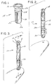
- Fig. 1 is a top perspective view of a vented cap in accordance with the invention;
- Fig. 2 is a top perspective view of a vented cap and capillary tube assembly positioned above a person's finger;
- Fig. 3 is a top perspective view of the assembly shown in Fig. 2 in contact with the finger;
- Fig. 4 is a sectional view taken along line 4-4 of Fig. 3;
- Fig. 5 is a sectional view of the assembly showing the vented cap in a fully inserted position within the capillary tube, the capillary tube being in an inverted position;
- Fig. 6 is a sectional view of an alternative embodiment of a capillary tube assembly according to the invention; and
- Fig. 7 is a perspective view of a cap employed in the assembly shown in Fig. 6.
- A vented cap and a
capillary tube assembly 10 as shown in Figs. 1 and 2-5, respectively, are disclosed herein. Thecapillary tube 12 includes cylindrical walls made from a transparent material such as glass. One end of the tube is open; the other end includes acap 14 mounted thereto. Thetube 12 is constructed to draw a selected amount of liquid or a suspension therein via capillary action or by the application of negative pressure. The terms liquid and suspension shall be used interchangeably herein. The dimensions of thetube 12 may vary depending upon the properties of the liquid to be drawn therein. - The
cap 14 according to the invention is best shown in Fig. 1. It includes an enlargedhead 16 and a substantially cylindrical body orplug 18 extending therefrom. The plug may have a maximum diameter of less than two millimeters if the cap is to be used for closing an end of a certain type of conventional glass capillary tube as used for blood sampling. Other diameters may alternatively be employed depending upon the diameter of the capillary tube to be used therewith. The cap is preferably of integral construction, and is made from a resilient, thermoplastic material such as SANTOPRENE(R) thermoplastic rubber, grade 201-73. This material is available from Monsanto Chemical Company of St. Louis, Missouri. A colorant such as titanium dioxide may be mixed with the thermoplastic rubber prior to molding the cap so that a reflective and substantially opaque product is provided. The cap may be coated with a silicone oil such as dimethylpolysiloxane. - Two
elongated grooves 20 are provided within thecylindrical plug 18. Each of the grooves runs substantially parallel to the longitudinal axis of the cylindrical plug. Thegrooves 20 are diametrically opposed to each other. Each includes an inlet portion adjacent to the bottom end of theplug 18. - An
annular groove 22 is defined by the exterior surface of thecylindrical plug 18 where it adjoins theenlarged head 16 of thecap 14. A protrudingring 24, which is employed as a sealing ring for engaging the inner wall of thetube 12, is also defined by theplug 18. The elongate,longitudinal grooves 20 include outlet portions extending partially into thering 24. - The
end 26 of theplug 18 opposite from theenlarged head 16 is tapered to facilitate its insertion within a capillary tube or the like. The taper is defined by a spherical radius between the cylindrical body portion and an end surface of the plug. - As shown in Figs. 2-3, the
cap 14 andtube 12 are provided to the user as a pre-assembled construction which allows air to vent through the cap. Liquid is drawn into the tube with the cap in this position. The open end of the capillary tube is inserted within a liquid, as shown in Figs. 3 and 4. Liquid is drawn within the tube via capillary action or via a mechanical pipetter. As the liquid approaches thecap 14, the displaced air within the tube moves through thevent grooves 22 and is vented to the atmosphere. - Once a sufficient amount of liquid has been drawn into the
capillary tube 12, thecap 14 is moved to the position shown in Fig. 5. In this position, the outlet portion of eachvent groove 20 is closed by the sealing engagement of the sealingring 24 with the inner wall of thecapillary tube 12. The lower surface of theenlarged head 16 of thecap 14 abuts against the end surface of the capillary tube, thereby providing an additional seal. Theannular groove 22 allows the cap to be fully inserted despite the fact that the resilient material from which the cap is made tends to be displaced rearwardly during insertion. If a bulge were formed adjacent to theenlarged head 16 due to such displacement, it would engage the end of the tube and thereby prevent theenlarged head 16 from doing so. - The
assembly 10 as shown in Fig. 5 may be mounted within a centrifuge, if the liquid is blood, to separate the blood components into discrete layers. Different procedures may, of course, be performed with blood or other liquid samples. - This assembly may be used to advantage in sampling and analyzing blood. It is particularly suitable for facilitating quantitative buffy coat (QBC) analysis and/or hematocrit tests. The cap, being opaque, is easily distinguished from the red blood cells when the blood sample is analyzed.
- The
capillary tube 12, if to be used for quantitative buffy coat analysis, is provided as a preassembled device including thecap 14, aplastic float 28, and appropriate coatings within the tube. The inner wall of the uncapped end of the tube is preferably coated with ananticoagulent 30. A more central portion of the inner wall of the tube is coated withacridine orange 32, which acts as a supravital stain. Theassembly 10 is constructed by flaming one end of the tube to remove sharp edges and to retain the float within the tube. The tube is then coated with the acridine orange, and subsequently with the anticoagulent. The float is installed, and the tube is then capped. - The sealing
ring 24 provides two functions, one of which is to provide a seal between thecap 14 and inner wall of the capillary tube as described above. The ring also prevents the cap from moving too far into the tube unless intentionally pushed in. Since the cap may be preassembled to the tube, theassembly 10 could be subject to vibrations and other movements during storage or shipment. This could tend to cause the cap to settle further into the tube than originally placed, even though theplug 18 is in frictional engagement with the inner wall of the capillary tube. If the cap moved too far in, the vent grooves would be sealed off. As air in the tube could no longer be displaced through the vent grooves, the tube could not be filled via capillary action. In accordance with the invention, thering 24 has a diameter which is sufficiently large that the lower surface thereof will frictionally engage the top end of thecapillary tube 12, slightly deforming the ring. The frictional forces exerted by the ring against the top end of the tube are sufficient that the cap will not move further within the tube unless intentionally pushed. Since thevent grooves 20 extend beyond the lower edge of the ring, the seating of the lower edge of the ring on the end of the capillary tube will not cause them to be sealed off. Theassembly 10 may accordingly be used to draw liquid via capillary action. - Once a desired volume of liquid is drawn into the capillary tube, the cap is fully inserted in the tube to close off the vent grooves. If the assembly is to be used for performing quantitative buffy coat analysis, the assembly is then subjected to centrifugation to separate the blood into red blood cells, plasma, and an expanded buffy coat between the plasma and red blood cell layers. The
opaque cap 14 provides a clear interface between it and the red blood cells, while the plastic float causes the layers of platelets, nongranulocytes, and granulocytes to be greatly expanded. These layers can be observed either directly through a magnifier, or by machine. - The
assembly 10 can also be filled with a liquid by inserting the capped end into a liquid sample and aspirating liquid through the vents. The cap would then be pushed into the tube to seal off the vent grooves. This procedure is less preferred than filling the capillary tube by capillary action via the uncapped end of the assembly, as described above. - An important feature of the present invention is the ability of the
vent grooves 20 to remain open despite the compressive forces which are exerted by the capillary tube upon theplug 18. Since the dimensions of thecap 14 are very small, the vent grooves are necessarily small. Very little distortion of the plug would be required to close off one or both vent grooves. - A specific cap shall be described herein for the sole purpose of demonstrating the general size of a cap used for sealing a capillary tube. It will be appreciated that the dimensions of the cap will, of course, vary depending upon the size of the tube or vessel in which it is to be used. A cap used for sealing a glass capillary tube of the type used for sampling and analyzing blood may be between about two and two and one half millimeters (0.079-0.098 inches) in length. The diameter of the plug is about 1.7 millimeters (0.067-0.069 inches) while that of the
enlarged head 16 is about 2.2 millimeters (0.086-0.088 inches). Each vent groove has a width of about three quarters of a millimeter (about 0.03 inches) and a maximum depth of about 0.37 millimeters (0.015 inches). - The materials from which the cap is made must be carefully chosen so that the plug is not significantly distorted upon its engagement with the inner wall of a capillary tube. It should also be hydrophobic so that air can escape through the vent grooves, but not blood which may contact the cap. The preferred material, SANTOPRENE(R) thermoplastic rubber, is a relatively soft grade of thermoplastic rubber having a hardness of 73 Shore A under ASTM Test method D2240 conducted at 25°C. The stress-strain curve for this material is elastomeric at ambient temperatures. The elastomeric properties of SANTOPRENE(R) thermoplastic rubber allow the plug to frictionally engage the inner wall of a capillary tube so that it is firmly retained by the tube without collapsing the vent grooves. SANTOPRENE(R) thermoplastic rubber is also a slippery material, which facilitates inserting the plug within a capillary tube without causing significant distortion. It is sufficiently slippery that coating the
cap 14 with silicone oil, as described above, may not always be necessary. - An alternative embodiment of the invention is shown in Figs. 6-7. A capillary tube/cap assembly 100 is provided which includes a cylindrical capillary tube 112 having a pair of open ends. A
float 28 is positioned within the tube, while a cap 114 is mounted to one end thereof. The cap includes a top wall 116, a plug 118 extending from the center of the top wall, and a generally cylindrical, resilient skirt 119 which extends from the periphery of the top wall. The plug and skirt are substantially coaxial. - A plurality of longitudinal grooves 120 are defined within the interior surface of the skirt 119. A sealing ring 126 extends radially inwardly from this interior surface. The sealing ring is adapted to rest upon an end surface of the capillary tube when the cap is in the "venting" position. The grooves 120 extend partially through the sealing ring, thereby insuring that air can escape through the grooves when this ring is seated upon the end of the capillary tube.
- The cap 114 is pushed forcefully towards the tube in order to seal one end thereof. Once this occurs, the portion of the sealing ring 126 which is above the vent grooves 120 seals the cap against the outer surface of the tube while the plug 118 provides an additional seal by engaging the inner surface of the tube. It will be appreciated that the sealing assemblies employed in the
caps 14 shown in Figs. 1 and 6 may be comprised of two parallel rings, the vent grooves extending through the lower of the two rings.
Claims (7)
- A vented cap and capillary tube assembly comprising:
a capillary tube (12;112) having a pair of open ends,
a cap (14;114) slidably mounted to one of the ends of said capillary tube (12;112) and
a vent groove (20;120) being positioned such that air within said capillary tube (12;112) can be passed through said vent groove (20;120) to the atmosphere when said cap (14;114) is in a first axial position with respect to said capillary tube (12;112), and wherein said vent groove (20;120) is sealed once said cap (14;114) is slidably moved along the axis of said capillary tube (12;112) to a second position with respect to said capillary tube (12;112),
characterized in that
a float (28) is contained in a cavity of the capillary tube (12;112), said float cooperating with the capillary tube (12;112) to provide a capillary path for drawing in a liquid, and
said cap (14;114) is elastomeric and includes a non-hydrophilic external surface, and
the capillary tube (12;112) is vented through the vent groove (20), the vent groove extending along the elastomeric cap (14;114), allowing the passage of air, but not blood, therethrough when said cap (14) is in the first axial position, said groove (20;120) being sealed by a surface of said capillary tube (12;112). - An assembly as defined in claim 1, wherein said cap (14) includes an enlarged head portion (16) and a substantially cylindrical plug (18) extending from said enlarged head portion (16), said plug (18) extending within one of the ends of said capillary tube (12), the vent groove (20) being defined within the outer surface of said plug (18).
- An assembly as defined in claim 2 wherein said plug (18) includes an area of reduced diameter adjoining said enlarged head portion (16).
- An assembly as defined in claim 2 or 3 wherein said vent groove (20) extends substantially parallel to the longitudinal axis of said plug (18).
- An assembly as defined in one of claims 2-4 wherein said plug (18) includes an annular ring (24) projecting radially therefrom.
- An assembly as defined in claim 1 wherein said cap (114) includes a vent groove (120) defined by an inner surface thereof, said cap (114) further including an integral ring (126) for engaging a wall of said capillary tube (112), said vent groove (120) extending at least partially within said ring (126) such that said vent groove (120) remains open when the bottom surface of said ring (126) engages an end of said capillary tube (112), said vent groove (120) being closed by a portion of said cap (114) and said capillary tube (112) when said cap (114) is fully engaged with said capillary tube (112).
- A closure for a vented cap and capillary tube assembly as defined in one of claims 1-5 comprising:
an integral body including an enlarged head portion (16) and a substantially cylindrical plug (18) extending from said enlarged head portion (16),
vent grooves (20) extending substantially longitudinally with an exterior surface of said plug (18), and
an annular recess (22) is defined by the exterior surface of the cylindrical plug (18) where it adjoins the enlarged head (16) of the cap (14).
Applications Claiming Priority (2)
| Application Number | Priority Date | Filing Date | Title |
|---|---|---|---|
| US07/711,844 US5203825A (en) | 1991-06-07 | 1991-06-07 | Capillary tube assembly including a vented cap |
| US771844 | 2001-01-29 |
Publications (3)
| Publication Number | Publication Date |
|---|---|
| EP0517121A2 EP0517121A2 (en) | 1992-12-09 |
| EP0517121A3 EP0517121A3 (en) | 1993-03-17 |
| EP0517121B1 true EP0517121B1 (en) | 1996-08-14 |
Family
ID=24859768
Family Applications (1)
| Application Number | Title | Priority Date | Filing Date |
|---|---|---|---|
| EP92109157A Expired - Lifetime EP0517121B1 (en) | 1991-06-07 | 1992-05-30 | Capillary tube assembly including a vented cap |
Country Status (6)
| Country | Link |
|---|---|
| US (2) | US5203825A (en) |
| EP (1) | EP0517121B1 (en) |
| JP (1) | JP2878021B2 (en) |
| AU (1) | AU647277B2 (en) |
| CA (1) | CA2070107C (en) |
| DE (1) | DE69212712T2 (en) |
Families Citing this family (64)
| Publication number | Priority date | Publication date | Assignee | Title |
|---|---|---|---|---|
| US5456885A (en) * | 1993-07-12 | 1995-10-10 | Coleman; Charles M. | Fluid collection, separation and dispensing tube |
| US5431280A (en) * | 1994-03-17 | 1995-07-11 | Humagen Fertility Diagnostics Inc. | Closure cap for holding pipets during shipping |
| US5460782A (en) * | 1994-07-18 | 1995-10-24 | Safe-Tec Clinical Products, Inc. | Automatic filling micropipette with dispensing means |
| DE4428434A1 (en) * | 1994-08-11 | 1996-02-15 | Boehringer Ingelheim Kg | Sealing cap and method for filling gas-free containers |
| US5613615A (en) * | 1995-07-26 | 1997-03-25 | Bunzl Plastics, Incorporated | Venting cap for masking |
| DE19615422A1 (en) | 1996-04-19 | 1997-11-20 | Boehringer Ingelheim Kg | Two-chamber cartridge for propellant-free MDIs |
| JP2985816B2 (en) * | 1997-02-04 | 1999-12-06 | 日本電気株式会社 | Liquid sampling device |
| US5855289A (en) * | 1997-04-25 | 1999-01-05 | Beckman Instruments, Inc. | Centrifugally loaded self-sealing integral one-piece cap/closure |
| US6062407A (en) * | 1997-04-25 | 2000-05-16 | Beckman Coulter, Inc. | Centrifugally loaded self-sealing integral one-piece cap/closure |
| US5899349A (en) * | 1997-10-02 | 1999-05-04 | Beckman Instruments, Inc. | Cap/closure having a venting mechanism for use with centrifuge containers |
| US6244022B1 (en) * | 1997-11-26 | 2001-06-12 | The Popstraw Company | Method for packaging a liquid filled container and a capsule therefor |
| US6074883A (en) * | 1998-03-02 | 2000-06-13 | Becton, Dickinson And Company | Method for using disposable blood tube holder |
| DE19851404A1 (en) * | 1998-11-07 | 2000-05-11 | Boehringer Ingelheim Int | Pressure compensation device for a double tank |
| WO2000047115A1 (en) * | 1999-02-10 | 2000-08-17 | Sub-Q, Inc. | Device and method for facilitating hemostasis of a biopsy tract |
| GB9917325D0 (en) | 1999-07-23 | 1999-09-22 | Clinical Diagnostic Chemicals | Apparatus for collecting a liquid sample |
| US7947236B2 (en) | 1999-12-03 | 2011-05-24 | Becton, Dickinson And Company | Device for separating components of a fluid sample |
| FR2804940B1 (en) * | 2000-02-10 | 2002-08-30 | Au Liegeur Ets J Pontneau Deni | CAP FOR BOTTLES WITH SPARKLING WINES AND METHOD FOR MANUFACTURING SUCH A CAP |
| US6513550B1 (en) * | 2001-07-27 | 2003-02-04 | Illinois Took Works Inc. | Two-piece cap for a vent hose |
| US6705349B2 (en) * | 2001-10-22 | 2004-03-16 | General Electric Company | Weep plug |
| US7992725B2 (en) | 2002-05-03 | 2011-08-09 | Biomet Biologics, Llc | Buoy suspension fractionation system |
| US20030205538A1 (en) | 2002-05-03 | 2003-11-06 | Randel Dorian | Methods and apparatus for isolating platelets from blood |
| US7832566B2 (en) | 2002-05-24 | 2010-11-16 | Biomet Biologics, Llc | Method and apparatus for separating and concentrating a component from a multi-component material including macroparticles |
| US7179391B2 (en) * | 2002-05-24 | 2007-02-20 | Biomet Manufacturing Corp. | Apparatus and method for separating and concentrating fluids containing multiple components |
| US7374678B2 (en) * | 2002-05-24 | 2008-05-20 | Biomet Biologics, Inc. | Apparatus and method for separating and concentrating fluids containing multiple components |
| US7845499B2 (en) | 2002-05-24 | 2010-12-07 | Biomet Biologics, Llc | Apparatus and method for separating and concentrating fluids containing multiple components |
| US20060278588A1 (en) | 2002-05-24 | 2006-12-14 | Woodell-May Jennifer E | Apparatus and method for separating and concentrating fluids containing multiple components |
| US7074577B2 (en) * | 2002-10-03 | 2006-07-11 | Battelle Memorial Institute | Buffy coat tube and float system and method |
| US6878046B2 (en) * | 2002-11-08 | 2005-04-12 | Safety-Kleen Systems, Inc. | Cleaning apparatus |
| ATE463202T1 (en) * | 2002-12-30 | 2010-04-15 | Hoffmann La Roche | CAPILLARY TUBE TIP DESIGN TO SUPPORT BLOOD FLOW |
| AU2003267187A1 (en) * | 2003-09-12 | 2005-04-27 | Garry Tsaur | Specimen collector |
| US20050196319A1 (en) * | 2004-03-03 | 2005-09-08 | Hach Company | System and method for providing a reaction surface of a predetermined area for a limited volume |
| US20060134354A1 (en) * | 2004-12-16 | 2006-06-22 | Walters Jay M | Calibration vial stopper with improved security features |
| DE102005029746B4 (en) | 2005-06-24 | 2017-10-26 | Boehringer Ingelheim International Gmbh | atomizer |
| CA2614352A1 (en) * | 2005-07-07 | 2007-01-18 | Rodrigues Fernando Carvalhais | A fixing system for joints, finishing profiles and decorative profiles |
| US8567609B2 (en) | 2006-05-25 | 2013-10-29 | Biomet Biologics, Llc | Apparatus and method for separating and concentrating fluids containing multiple components |
| US7771655B2 (en) * | 2006-07-12 | 2010-08-10 | Bayer Healthcare Llc | Mechanical device for mixing a fluid sample with a treatment solution |
| FR2909975B1 (en) * | 2006-12-13 | 2009-04-17 | Eskiss Packaging Soc Par Actio | BOTTLE FOR RECEIVING A DETERMINED DOSE OF A LIQUID |
| US7806276B2 (en) | 2007-04-12 | 2010-10-05 | Hanuman, Llc | Buoy suspension fractionation system |
| US8328024B2 (en) | 2007-04-12 | 2012-12-11 | Hanuman, Llc | Buoy suspension fractionation system |
| FR2925469B1 (en) * | 2007-12-19 | 2011-10-14 | Coradin Sas | PACKAGING FOR A LIQUID |
| EP2259774B1 (en) | 2008-02-27 | 2012-12-12 | Biomet Biologics, LLC | Methods and compositions for delivering interleukin-1 receptor antagonist |
| WO2009111338A1 (en) | 2008-02-29 | 2009-09-11 | Biomet Manufacturing Corp. | A system and process for separating a material |
| CN102149472B (en) | 2008-07-21 | 2014-08-13 | 贝克顿·迪金森公司 | Density phase separation device |
| AU2009274096B2 (en) | 2008-07-21 | 2012-08-02 | Becton, Dickinson And Company | Density phase separation device |
| MX366109B (en) | 2008-07-21 | 2019-06-26 | Becton Dickinson Co | Density phase separation device. |
| US8187475B2 (en) | 2009-03-06 | 2012-05-29 | Biomet Biologics, Llc | Method and apparatus for producing autologous thrombin |
| US8313954B2 (en) | 2009-04-03 | 2012-11-20 | Biomet Biologics, Llc | All-in-one means of separating blood components |
| CA2662546A1 (en) * | 2009-04-15 | 2010-10-15 | Spartan Bioscience Inc. | Tube for dna reactions |
| NZ596537A (en) | 2009-05-15 | 2014-11-28 | Becton Dickinson Co | Density phase separation device |
| US9011800B2 (en) | 2009-07-16 | 2015-04-21 | Biomet Biologics, Llc | Method and apparatus for separating biological materials |
| US8591391B2 (en) | 2010-04-12 | 2013-11-26 | Biomet Biologics, Llc | Method and apparatus for separating a material |
| US9642956B2 (en) | 2012-08-27 | 2017-05-09 | Biomet Biologics, Llc | Apparatus and method for separating and concentrating fluids containing multiple components |
| US9895418B2 (en) | 2013-03-15 | 2018-02-20 | Biomet Biologics, Llc | Treatment of peripheral vascular disease using protein solutions |
| US9950035B2 (en) | 2013-03-15 | 2018-04-24 | Biomet Biologics, Llc | Methods and non-immunogenic compositions for treating inflammatory disorders |
| US10143725B2 (en) | 2013-03-15 | 2018-12-04 | Biomet Biologics, Llc | Treatment of pain using protein solutions |
| US10208095B2 (en) | 2013-03-15 | 2019-02-19 | Biomet Manufacturing, Llc | Methods for making cytokine compositions from tissues using non-centrifugal methods |
| US20140271589A1 (en) | 2013-03-15 | 2014-09-18 | Biomet Biologics, Llc | Treatment of collagen defects using protein solutions |
| US9694359B2 (en) | 2014-11-13 | 2017-07-04 | Becton, Dickinson And Company | Mechanical separator for a biological fluid |
| EP3573900A1 (en) | 2017-01-24 | 2019-12-04 | Nolato Treff AG Degersheim | Receiving container, method for filling a receiving container, method for transporting receiving containers and use of a receiving container |
| US20210154664A1 (en) * | 2017-05-16 | 2021-05-27 | Agilent Technologies, Inc. | Headspace eliminating microtiter plate lid and method of optically measuring well oxygen concentration through the lid |
| JP6754142B2 (en) * | 2018-08-30 | 2020-09-09 | 株式会社シン・コーポレイション | Capillary sealant and trace sampling device |
| CN113249196A (en) * | 2021-05-06 | 2021-08-13 | 北京谊安和景生物科技有限公司 | Thermal expansion and cold contraction type integrated reaction tube |
| EP4279098A1 (en) * | 2022-05-18 | 2023-11-22 | Terumo Europe NV | Packaged needle assembly |
| WO2023222800A1 (en) | 2022-05-18 | 2023-11-23 | Terumo Europe Nv | Packaged needle assembly |
Family Cites Families (25)
| Publication number | Priority date | Publication date | Assignee | Title |
|---|---|---|---|---|
| US3164279A (en) * | 1965-01-05 | Test tube closure | ||
| US2649245A (en) * | 1947-04-24 | 1953-08-18 | Rudolph Grave Aktiebolag | Concentrating vessel and stopper therefor |
| US2655280A (en) * | 1948-08-12 | 1953-10-13 | Astell Lab Service Company Ltd | Bung or stopper |
| US3297184A (en) * | 1963-11-05 | 1967-01-10 | B D Lab Inc | Cap for culture tubes |
| US3834571A (en) * | 1972-11-20 | 1974-09-10 | Warner Lambert Co | Container closure for lyophilized products |
| US3901402A (en) * | 1973-03-14 | 1975-08-26 | Becton Dickinson Co | Stopper-piston |
| LU70300A1 (en) * | 1974-06-12 | 1976-04-13 | ||
| US3948261A (en) * | 1974-11-27 | 1976-04-06 | American Home Products Corporation | Unit dose container for surface administered vaccines |
| CH603168A5 (en) * | 1975-03-21 | 1978-08-15 | Dematex Dev & Invest | |
| US4204606A (en) * | 1975-03-21 | 1980-05-27 | Dematex Development & Investment Establishment | Tube and stopper combination with venting structure |
| US4049152A (en) * | 1976-01-09 | 1977-09-20 | Makap Limited | Closure caps for vessels |
| US4111326A (en) * | 1976-03-04 | 1978-09-05 | Becton, Dickinson And Company | Closure for air evacuated container |
| US4065018A (en) * | 1976-08-02 | 1977-12-27 | William J. Megowen | Closure means and method |
| US4076142A (en) * | 1977-01-19 | 1978-02-28 | Naz John F | Self-venting bottle closure |
| FR2416848A1 (en) * | 1978-02-08 | 1979-09-07 | Rumpler Jean Jacques | MEDICINAL PRODUCT CONTAINER CAP |
| US4192429A (en) * | 1978-03-02 | 1980-03-11 | Becton, Dickinson And Company | Vented vacuum tube and stopper |
| US4175671A (en) * | 1978-05-01 | 1979-11-27 | Caterpillar Tractor Co. | Breather cap |
| DE2848535C2 (en) * | 1978-11-09 | 1982-12-02 | Walter Sarstedt Kunststoff-Spritzgußwerk, 5223 Nümbrecht | Blood collection device |
| US4293078A (en) * | 1979-11-01 | 1981-10-06 | Becton, Dickinson And Company | Vacuum indicator closure for a blood collection tube |
| DK148782C (en) * | 1980-10-31 | 1986-04-21 | Radiometer As | PROCEDURE AND CLOSURE CAP FOR ANAEROBIC SEALING OF A BLOOD TEST CAPILLAR |
| US4411163A (en) * | 1981-07-27 | 1983-10-25 | American Hospital Supply Corporation | Ventable sample collection device |
| US4589421A (en) * | 1984-03-14 | 1986-05-20 | Syntex (U.S.A.) Inc. | Sampling device |
| US4650083A (en) * | 1985-06-06 | 1987-03-17 | William Lembeck | Safety closure for use in conjunction with bottling of champagne and other sparkling wines |
| GB8626765D0 (en) * | 1986-11-10 | 1986-12-10 | Unilever Plc | Self-sealing closure |
| US4883641A (en) * | 1987-06-26 | 1989-11-28 | Minnesota Mining And Manufacturing Company | Closure and container assembly for biological sterility indicator |
-
1991
- 1991-06-07 US US07/711,844 patent/US5203825A/en not_active Expired - Fee Related
-
1992
- 1992-05-30 EP EP92109157A patent/EP0517121B1/en not_active Expired - Lifetime
- 1992-05-30 DE DE69212712T patent/DE69212712T2/en not_active Expired - Lifetime
- 1992-06-01 AU AU17329/92A patent/AU647277B2/en not_active Ceased
- 1992-06-01 CA CA002070107A patent/CA2070107C/en not_active Expired - Fee Related
- 1992-06-08 JP JP4147379A patent/JP2878021B2/en not_active Expired - Lifetime
-
1993
- 1993-01-21 US US08/007,313 patent/US5325977A/en not_active Expired - Lifetime
Also Published As
| Publication number | Publication date |
|---|---|
| AU1732992A (en) | 1992-12-10 |
| DE69212712D1 (en) | 1996-09-19 |
| EP0517121A3 (en) | 1993-03-17 |
| JP2878021B2 (en) | 1999-04-05 |
| US5203825A (en) | 1993-04-20 |
| EP0517121A2 (en) | 1992-12-09 |
| JPH05172713A (en) | 1993-07-09 |
| CA2070107A1 (en) | 1992-12-08 |
| US5325977A (en) | 1994-07-05 |
| CA2070107C (en) | 1996-03-05 |
| DE69212712T2 (en) | 1997-03-06 |
| AU647277B2 (en) | 1994-03-17 |
Similar Documents
| Publication | Publication Date | Title |
|---|---|---|
| EP0517121B1 (en) | Capillary tube assembly including a vented cap | |
| EP0126390B1 (en) | Fluid transfer method and device | |
| EP1516585B1 (en) | Non-evacuated blood collection tube | |
| EP3320974B1 (en) | Specimen collection container assembly | |
| US5202093A (en) | Sealing cap with a one way valve having semi-cylindrical valve closure springs | |
| CA2211126C (en) | Ball and socket closure | |
| JP2001224982A (en) | Component separating appliance of fluid sample and method for the same | |
| US4055501A (en) | Fluid collection device with phase partitioning means | |
| US5169602A (en) | Resealable conduit and method | |
| GB1559344A (en) | Phase seperation device | |
| JPS5910349A (en) | Cock of analytical container | |
| US4052320A (en) | Telescoping serum separator and dispenser | |
| CA2083489A1 (en) | Method and apparatus for pipetting liquid from a sealed container | |
| CA2271337C (en) | Universal plug | |
| AU8320098A (en) | Ball and socket closure for specimen collection container incorporating an integral flexible seal | |
| AU8320398A (en) | Ball and socket closure for specimen collection container | |
| US3977568A (en) | Biological fluid dispenser for dispensing micro amounts | |
| US6054326A (en) | Fluid testing and analysing device and method | |
| US5249711A (en) | Disposable dispensing pipette | |
| CA1219469A (en) | Liquid sampling apparatus with retention means | |
| EP0732973B1 (en) | A method for collecting small quantities of liquid samples and sample containers for collecting small liquid quantities | |
| US5869158A (en) | Safety sampler | |
| US3626762A (en) | Method and apparatus for filling a capillary tube with liquid | |
| US6601889B2 (en) | Air-tight bailer system | |
| KR890001537B1 (en) | Sampling tube for ruine |
Legal Events
| Date | Code | Title | Description |
|---|---|---|---|
| PUAI | Public reference made under article 153(3) epc to a published international application that has entered the european phase |
Free format text: ORIGINAL CODE: 0009012 |
|
| AK | Designated contracting states |
Kind code of ref document: A2 Designated state(s): BE DE FR GB IT |
|
| PUAL | Search report despatched |
Free format text: ORIGINAL CODE: 0009013 |
|
| AK | Designated contracting states |
Kind code of ref document: A3 Designated state(s): BE DE FR GB IT |
|
| 17P | Request for examination filed |
Effective date: 19930220 |
|
| 17Q | First examination report despatched |
Effective date: 19940725 |
|
| GRAH | Despatch of communication of intention to grant a patent |
Free format text: ORIGINAL CODE: EPIDOS IGRA |
|
| GRAA | (expected) grant |
Free format text: ORIGINAL CODE: 0009210 |
|
| AK | Designated contracting states |
Kind code of ref document: B1 Designated state(s): BE DE FR GB IT |
|
| REF | Corresponds to: |
Ref document number: 69212712 Country of ref document: DE Date of ref document: 19960919 |
|
| ET | Fr: translation filed | ||
| ITF | It: translation for a ep patent filed |
Owner name: ING. C. GREGORJ S.P.A. |
|
| PLBE | No opposition filed within time limit |
Free format text: ORIGINAL CODE: 0009261 |
|
| STAA | Information on the status of an ep patent application or granted ep patent |
Free format text: STATUS: NO OPPOSITION FILED WITHIN TIME LIMIT |
|
| 26N | No opposition filed | ||
| PGFP | Annual fee paid to national office [announced via postgrant information from national office to epo] |
Ref country code: BE Payment date: 20000523 Year of fee payment: 9 |
|
| PG25 | Lapsed in a contracting state [announced via postgrant information from national office to epo] |
Ref country code: BE Free format text: LAPSE BECAUSE OF NON-PAYMENT OF DUE FEES Effective date: 20010531 |
|
| BERE | Be: lapsed |
Owner name: BECTON DICKINSON AND CY Effective date: 20010531 |
|
| REG | Reference to a national code |
Ref country code: GB Ref legal event code: IF02 |
|
| PGFP | Annual fee paid to national office [announced via postgrant information from national office to epo] |
Ref country code: IT Payment date: 20070608 Year of fee payment: 16 |
|
| PGFP | Annual fee paid to national office [announced via postgrant information from national office to epo] |
Ref country code: FR Payment date: 20070530 Year of fee payment: 16 |
|
| REG | Reference to a national code |
Ref country code: FR Ref legal event code: ST Effective date: 20090119 |
|
| PG25 | Lapsed in a contracting state [announced via postgrant information from national office to epo] |
Ref country code: FR Free format text: LAPSE BECAUSE OF NON-PAYMENT OF DUE FEES Effective date: 20080602 |
|
| PG25 | Lapsed in a contracting state [announced via postgrant information from national office to epo] |
Ref country code: IT Free format text: LAPSE BECAUSE OF NON-PAYMENT OF DUE FEES Effective date: 20080530 |
|
| PGFP | Annual fee paid to national office [announced via postgrant information from national office to epo] |
Ref country code: GB Payment date: 20110525 Year of fee payment: 20 |
|
| PGFP | Annual fee paid to national office [announced via postgrant information from national office to epo] |
Ref country code: DE Payment date: 20110527 Year of fee payment: 20 |
|
| REG | Reference to a national code |
Ref country code: DE Ref legal event code: R071 Ref document number: 69212712 Country of ref document: DE |
|
| REG | Reference to a national code |
Ref country code: DE Ref legal event code: R071 Ref document number: 69212712 Country of ref document: DE |
|
| REG | Reference to a national code |
Ref country code: GB Ref legal event code: PE20 Expiry date: 20120529 |
|
| PG25 | Lapsed in a contracting state [announced via postgrant information from national office to epo] |
Ref country code: DE Free format text: LAPSE BECAUSE OF EXPIRATION OF PROTECTION Effective date: 20120531 |
|
| PG25 | Lapsed in a contracting state [announced via postgrant information from national office to epo] |
Ref country code: GB Free format text: LAPSE BECAUSE OF EXPIRATION OF PROTECTION Effective date: 20120529 |