EP0517253B1 - Vehicle passenger restraint device for use in automotive vehicle or the like - Google Patents
Vehicle passenger restraint device for use in automotive vehicle or the like Download PDFInfo
- Publication number
- EP0517253B1 EP0517253B1 EP92109558A EP92109558A EP0517253B1 EP 0517253 B1 EP0517253 B1 EP 0517253B1 EP 92109558 A EP92109558 A EP 92109558A EP 92109558 A EP92109558 A EP 92109558A EP 0517253 B1 EP0517253 B1 EP 0517253B1
- Authority
- EP
- European Patent Office
- Prior art keywords
- circuit
- sec
- output
- signal
- level
- Prior art date
- Legal status (The legal status is an assumption and is not a legal conclusion. Google has not performed a legal analysis and makes no representation as to the accuracy of the status listed.)
- Expired - Lifetime
Links
Images


Classifications
-
- B—PERFORMING OPERATIONS; TRANSPORTING
- B60—VEHICLES IN GENERAL
- B60R—VEHICLES, VEHICLE FITTINGS, OR VEHICLE PARTS, NOT OTHERWISE PROVIDED FOR
- B60R21/00—Arrangements or fittings on vehicles for protecting or preventing injuries to occupants or pedestrians in case of accidents or other traffic risks
- B60R21/01—Electrical circuits for triggering passive safety arrangements, e.g. airbags, safety belt tighteners, in case of vehicle accidents or impending vehicle accidents
- B60R21/013—Electrical circuits for triggering passive safety arrangements, e.g. airbags, safety belt tighteners, in case of vehicle accidents or impending vehicle accidents including means for detecting collisions, impending collisions or roll-over
- B60R21/0132—Electrical circuits for triggering passive safety arrangements, e.g. airbags, safety belt tighteners, in case of vehicle accidents or impending vehicle accidents including means for detecting collisions, impending collisions or roll-over responsive to vehicle motion parameters, e.g. to vehicle longitudinal or transversal deceleration or speed value
-
- B—PERFORMING OPERATIONS; TRANSPORTING
- B60—VEHICLES IN GENERAL
- B60R—VEHICLES, VEHICLE FITTINGS, OR VEHICLE PARTS, NOT OTHERWISE PROVIDED FOR
- B60R21/00—Arrangements or fittings on vehicles for protecting or preventing injuries to occupants or pedestrians in case of accidents or other traffic risks
- B60R21/01—Electrical circuits for triggering passive safety arrangements, e.g. airbags, safety belt tighteners, in case of vehicle accidents or impending vehicle accidents
- B60R21/013—Electrical circuits for triggering passive safety arrangements, e.g. airbags, safety belt tighteners, in case of vehicle accidents or impending vehicle accidents including means for detecting collisions, impending collisions or roll-over
-
- B—PERFORMING OPERATIONS; TRANSPORTING
- B60—VEHICLES IN GENERAL
- B60R—VEHICLES, VEHICLE FITTINGS, OR VEHICLE PARTS, NOT OTHERWISE PROVIDED FOR
- B60R21/00—Arrangements or fittings on vehicles for protecting or preventing injuries to occupants or pedestrians in case of accidents or other traffic risks
- B60R21/01—Electrical circuits for triggering passive safety arrangements, e.g. airbags, safety belt tighteners, in case of vehicle accidents or impending vehicle accidents
- B60R21/015—Electrical circuits for triggering passive safety arrangements, e.g. airbags, safety belt tighteners, in case of vehicle accidents or impending vehicle accidents including means for detecting the presence or position of passengers, passenger seats or child seats, and the related safety parameters therefor, e.g. speed or timing of airbag inflation in relation to occupant position or seat belt use
- B60R21/01512—Passenger detection systems
- B60R21/01542—Passenger detection systems detecting passenger motion
-
- B—PERFORMING OPERATIONS; TRANSPORTING
- B60—VEHICLES IN GENERAL
- B60R—VEHICLES, VEHICLE FITTINGS, OR VEHICLE PARTS, NOT OTHERWISE PROVIDED FOR
- B60R21/00—Arrangements or fittings on vehicles for protecting or preventing injuries to occupants or pedestrians in case of accidents or other traffic risks
- B60R21/01—Electrical circuits for triggering passive safety arrangements, e.g. airbags, safety belt tighteners, in case of vehicle accidents or impending vehicle accidents
- B60R21/015—Electrical circuits for triggering passive safety arrangements, e.g. airbags, safety belt tighteners, in case of vehicle accidents or impending vehicle accidents including means for detecting the presence or position of passengers, passenger seats or child seats, and the related safety parameters therefor, e.g. speed or timing of airbag inflation in relation to occupant position or seat belt use
- B60R21/01558—Electrical circuits for triggering passive safety arrangements, e.g. airbags, safety belt tighteners, in case of vehicle accidents or impending vehicle accidents including means for detecting the presence or position of passengers, passenger seats or child seats, and the related safety parameters therefor, e.g. speed or timing of airbag inflation in relation to occupant position or seat belt use monitoring crash strength
-
- B—PERFORMING OPERATIONS; TRANSPORTING
- B60—VEHICLES IN GENERAL
- B60R—VEHICLES, VEHICLE FITTINGS, OR VEHICLE PARTS, NOT OTHERWISE PROVIDED FOR
- B60R21/00—Arrangements or fittings on vehicles for protecting or preventing injuries to occupants or pedestrians in case of accidents or other traffic risks
- B60R21/01—Electrical circuits for triggering passive safety arrangements, e.g. airbags, safety belt tighteners, in case of vehicle accidents or impending vehicle accidents
- B60R21/017—Electrical circuits for triggering passive safety arrangements, e.g. airbags, safety belt tighteners, in case of vehicle accidents or impending vehicle accidents including arrangements for providing electric power to safety arrangements or their actuating means, e.g. to pyrotechnic fuses or electro-mechanic valves
- B60R21/0173—Diagnostic or recording means therefor
-
- G—PHYSICS
- G01—MEASURING; TESTING
- G01P—MEASURING LINEAR OR ANGULAR SPEED, ACCELERATION, DECELERATION, OR SHOCK; INDICATING PRESENCE, ABSENCE, OR DIRECTION, OF MOVEMENT
- G01P15/00—Measuring acceleration; Measuring deceleration; Measuring shock, i.e. sudden change of acceleration
- G01P15/02—Measuring acceleration; Measuring deceleration; Measuring shock, i.e. sudden change of acceleration by making use of inertia forces using solid seismic masses
- G01P15/08—Measuring acceleration; Measuring deceleration; Measuring shock, i.e. sudden change of acceleration by making use of inertia forces using solid seismic masses with conversion into electric or magnetic values
- G01P15/0891—Measuring acceleration; Measuring deceleration; Measuring shock, i.e. sudden change of acceleration by making use of inertia forces using solid seismic masses with conversion into electric or magnetic values with indication of predetermined acceleration values
-
- G—PHYSICS
- G01—MEASURING; TESTING
- G01P—MEASURING LINEAR OR ANGULAR SPEED, ACCELERATION, DECELERATION, OR SHOCK; INDICATING PRESENCE, ABSENCE, OR DIRECTION, OF MOVEMENT
- G01P21/00—Testing or calibrating of apparatus or devices covered by the preceding groups
-
- B—PERFORMING OPERATIONS; TRANSPORTING
- B60—VEHICLES IN GENERAL
- B60R—VEHICLES, VEHICLE FITTINGS, OR VEHICLE PARTS, NOT OTHERWISE PROVIDED FOR
- B60R21/00—Arrangements or fittings on vehicles for protecting or preventing injuries to occupants or pedestrians in case of accidents or other traffic risks
- B60R21/01—Electrical circuits for triggering passive safety arrangements, e.g. airbags, safety belt tighteners, in case of vehicle accidents or impending vehicle accidents
- B60R2021/01122—Prevention of malfunction
-
- B—PERFORMING OPERATIONS; TRANSPORTING
- B60—VEHICLES IN GENERAL
- B60R—VEHICLES, VEHICLE FITTINGS, OR VEHICLE PARTS, NOT OTHERWISE PROVIDED FOR
- B60R21/00—Arrangements or fittings on vehicles for protecting or preventing injuries to occupants or pedestrians in case of accidents or other traffic risks
- B60R21/01—Electrical circuits for triggering passive safety arrangements, e.g. airbags, safety belt tighteners, in case of vehicle accidents or impending vehicle accidents
- B60R21/013—Electrical circuits for triggering passive safety arrangements, e.g. airbags, safety belt tighteners, in case of vehicle accidents or impending vehicle accidents including means for detecting collisions, impending collisions or roll-over
- B60R2021/01311—Electrical circuits for triggering passive safety arrangements, e.g. airbags, safety belt tighteners, in case of vehicle accidents or impending vehicle accidents including means for detecting collisions, impending collisions or roll-over monitoring the braking system, e.g. ABS
-
- B—PERFORMING OPERATIONS; TRANSPORTING
- B60—VEHICLES IN GENERAL
- B60R—VEHICLES, VEHICLE FITTINGS, OR VEHICLE PARTS, NOT OTHERWISE PROVIDED FOR
- B60R21/00—Arrangements or fittings on vehicles for protecting or preventing injuries to occupants or pedestrians in case of accidents or other traffic risks
- B60R21/01—Electrical circuits for triggering passive safety arrangements, e.g. airbags, safety belt tighteners, in case of vehicle accidents or impending vehicle accidents
- B60R21/013—Electrical circuits for triggering passive safety arrangements, e.g. airbags, safety belt tighteners, in case of vehicle accidents or impending vehicle accidents including means for detecting collisions, impending collisions or roll-over
- B60R2021/01315—Electrical circuits for triggering passive safety arrangements, e.g. airbags, safety belt tighteners, in case of vehicle accidents or impending vehicle accidents including means for detecting collisions, impending collisions or roll-over monitoring occupant displacement
-
- B—PERFORMING OPERATIONS; TRANSPORTING
- B60—VEHICLES IN GENERAL
- B60R—VEHICLES, VEHICLE FITTINGS, OR VEHICLE PARTS, NOT OTHERWISE PROVIDED FOR
- B60R21/00—Arrangements or fittings on vehicles for protecting or preventing injuries to occupants or pedestrians in case of accidents or other traffic risks
- B60R21/01—Electrical circuits for triggering passive safety arrangements, e.g. airbags, safety belt tighteners, in case of vehicle accidents or impending vehicle accidents
- B60R21/015—Electrical circuits for triggering passive safety arrangements, e.g. airbags, safety belt tighteners, in case of vehicle accidents or impending vehicle accidents including means for detecting the presence or position of passengers, passenger seats or child seats, and the related safety parameters therefor, e.g. speed or timing of airbag inflation in relation to occupant position or seat belt use
- B60R21/01512—Passenger detection systems
- B60R21/01544—Passenger detection systems detecting seat belt parameters, e.g. length, tension or height-adjustment
- B60R21/01548—Passenger detection systems detecting seat belt parameters, e.g. length, tension or height-adjustment sensing the amount of belt winded on retractor
Definitions
- the invention relates to a passenger restraint device such as an air-bag as indicated in the precharacterizing part of claim 1.
- Fig. 1 shows a prior art air bag control circuit arrangement which is comprised of a DC source 51, a malfunction inhibitor sensor 52 detonators 53 and 54, and an impact sensor (acceleration switch) arrangement which includes two switches 55 and 56 connected in parallel.
- the malfunction inhibitor switch can take the form of a mercury switch or the like which is responsive to vehicle motion and indicates if the vehicle is at standstill or not.
- Fig. 2 To overcome these problems the arrangement shown in Fig. 2 has been proposed.
- This arrangement is such that the mechanical switch arrangement is replaced with a semi-conductor type acceleration sensor 67, an impact discrimination circuit 68 and a switching arrangement generally denoted by the numeral 613.
- the switching arrangement 613 includes two switching transistors 69 and 610 and two fixed current sources 611 and 612. The switching transistors and the current sources are paired and arranged in series with the detonators 63 and 64 in the illustrated manner.
- the impact discrimination circuit 68 is arranged to determine, based on the analog signal output by the acceleration sensor 7, if a collision which is apt to induced physical harm or death has occurred or not. In the event of an affirmative decision, the circuit 68 applies a voltage to the gates of the switching transistors in a manner which render the same conductive (viz., ON).
- the fixed current sources 611, 612 respond by causing currents to pass through the detonators 63 and 64 and thus induces the deployment of the air-bag or activation of the like type of restraining device.
- Fig. 3 shows another example of air bag control circuitry.
- This arrangement is disclosed in JP-A-49-55031.
- AB denotes an air-bag which is operatively connected with a impact detection type accelerometer or G sensor 71 via a timing circuit arrangement.
- the timing circuit arrangement includes an amplifier 72; a first comparator 74 which compares the output of the amplifier with a first predetermined slice level S1 and acts as a switch; an integrator 76; a second slice level comparator type switch circuit 78, and a pulse generator 710 which is operatively connected with an ignitor or squib 712.
- the latter mentioned element being used to detonate a charge which induces the required rapid gas generation.
- the output of the G sensor 71 is amplified and produces a signal which contains a DC component.
- this DC component containing signal exceeds the first slice level S1 in comparator 74, the device switches and the output is supplied to the integrator 76 which integrates the DC component and supplies the result to the second comparator 78.
- the second comparator 78 switches and produces an output which is supplied to the pulse generator 710 which in turn induces the ignition of the air bag inflation charge.
- Fig. 4 shows a second arrangement which is disclosed in the above mentioned document.
- an impact sensing G sensor 814 is operatively connected with an amplifier 816.
- the output of the amplifier 816 is connected to a slice level switch type circuit arrangement 818 which is arranged to output a signal in the event that the input exceeds a first slice level S1.
- a first integrator circuit 820 is operatively connected with the output terminals of both the amplifier 816 and the first slice level switch 818.
- a second integrator 822 is operatively connected with the output terminal of the first integrator 820 and the output terminal of a second slice level switch type circuit 824 which is arranged, as shown, to receive the output of the first integrator 820.
- a third slice level switch circuit arrangement 826 is connected to the output of the second integrator 822 and arranged to compare the output thereof with a predetermined slice level VK. Upon the slice level being reached, the third slice level switch circuit 826 outputs a signal to a pulse generator 828 which responds by inducing the ignition of an air bag inflation charge.
- Figs. 3 and 4 suffer from the drawbacks that they are unable to adequately distinguish between accidents wherein the initial amount of damage is large and that wherein the initial damage is relatively small for a given period and then rapidly increases. Viz., in the case a vehicle collides directly against a solid wall and the deceleration to which the occupant is subjected increases rapidly, it is very easy to determine that deployment of an air bag is desirable.
- the bag inflated too early, it will tend to be deflating when the passenger comes into contact with the same and thus not be able to provide the required cushioning and passenger movement attenuation. On the other hand, if the inflation of the bag is delayed, it will not be fully inflated at the time the maximum cushioning effect is required.
- Another prior art (US-A-4,975,850) passenger restraint system produces in accordance with an acceleration detector, a signal representing the existing condition of the vehicle. This condition signal is differentiated to produce a jerk signal. Only when the value of the condition signal exceeds a first threshold level a predetermined time period is timed. When the value of the jerk signal exceeds a jerk threshold level, a second signal is produced. Only when the second signal occurs during the predetermined time, a trigger signal is produced for actuating the restraint system. That is, a judgement is carried out as to whether or not the change rate or jerk of the vehicle acceleration is sufficient for actuating the restraint system. Consequently, also this prior art system cannot avoid generation of an erroneously timed activation trigger signal for the restraint device activating means.
- the ampount of damage which has occurred to the vehicle is predicted in response to the output of the acceleration sensing means
- an accelero-meter or G sensor unit 100 is arranged to supply its output to a low pass filter (LPF) 102.
- LPF low pass filter
- the output of LPF 102 is supplied to a first "displacement prediction" section SEC.01 of the system.
- This section comprises an ON/OFF type switch 103 and first and second serially connected partial integrators 104 and 106.
- the output terminal of the switch 103 is also connected with a first coefficient circuit 108.
- a second coefficient circuit 110 is arranged to receive an input from a junction defined between the first and second integrators 104, 106.
- the outputs of the second integrator 106 and the first and second coefficient circuits 108, 110 are supplied to an adder circuit 112.
- a threshold level type comparator or slice level switch 114 is arranged to receive the output (N) of the adder 112 and to output a signal (O) upon a predetermined slice level being exceeded.
- a second "G level" discrimination section SEC.02 of the system comprises first, second, third and fourth comparators 116, 118, 120 & 122 which are arranged in parallel and coupled so as to receive the output of the LPF 102 on their respective inputs.
- the second section further comprises first and second timer circuits 124, 126, an OR gate 128, a NOR gate 130 and first and second multivibrator or flip flop circuits 132, 134, coupled in the illustrated manner.
- the first comparator 116 is arranged to compare the filtered output of the G sensor unit and determine if the voltage level is indicative of a force in excess of 1.0G.
- the output (A) of the first comparator 116 is connected with the set terminal (S) of the first RS flip flop 132 and to the set terminal (S) of the first timer 124.
- the first timer 124 is arranged to respond to the presence of a high level signal on its set terminal in a manner to be triggered in manner to generate a high level signal (D) on its output for 70ms (for example).
- the second comparator 118 is arranged to compare the filtered signal from the G sensor unit and determine if the voltage is indicative of an acceleration of more than 05.G.
- This comparator 118 is arranged to normally output a high level signal (B) and switch a low level one in the event that the 0.5G level is exceeded.
- the output (B) of the second comparator 118 is supplied to the reset terminals (R) of both of the first and second timer circuits 124, 126 and to one of the two input terminals of the OR gate 128.
- the output (L) of the OR gate 128 is connected with reset terminal (R) of the first flip flop circuit 132.
- the outputs (D, F) of the first and second timers 124, 126 are supplied to the NOR gate 130.
- the output (K) of the NOR 130 is supplied to the second of the input terminals of the OR 128.
- the set terminal (S) of the second timer 126 is arranged to receive the output (E) of the third comparator 120.
- the comparator 120 is arranged to produce a high level output signal in the event that the output of the G sensor unit should indicate that the instant acceleration has reached or exceeded a 4.0G magnitude.
- the fourth comparator 122 is arranged to produce a high level in the event that the output of the G sensor unit is indicative of a 10.0G magnitude acceleration.
- the output (G) of the fourth comparator 122 is supplied to the set terminal of the second flip flop circuit 134.
- a third so called “damage discrimination" section SEC.03 of the system comprises: a high pass filter HPF (or alternatively a band pass filter BPF) 136, a "powering" circuit 138 (viz., a circuit which one of squares, cubes etc., the input), an integrator 140 and a threshold level comparator or slice level switch 142, all of which are connected in series.
- the output of the G sensor unit 100 is supplied to the input of the high pass filter HPF 136, while the output of the slice level switch 142 is supplied to the set terminal (R) of the flip flop 144.
- An OR gate 146 is connected to the output (Q) terminals of the flip flops 134, 144 while the reset terminals (R) of the same are connected with the NOR gate 130 to receive the output (K) therefrom.
- the outputs of the slice level switch 114 and the OR gate 146 are supplied to the input terminals of an AND gate 148.
- the output (P) of the AND 148 is supplied with an ignition device 150 used to induce the inflation of an air-bag device AB.
- the output (C) of the first flip flop circuit of the second section SEC.02 is used to open and close the switch 103 and is also applied as a reset for the three integrators 104, 106 and 140.
- the output characteristics of the G sensor unit follow trace 1 (viz., characteristics wherein the G force exceeds the 1.0G level and then tapers off in a manner so as to not exceed the 4.0G level).
- the output (B) of the second comparator 118 switches from a high level to a low one (see corresponding trace B in Fig. 6) This removes the signal which is constantly being applied to the reset terminals of the timers 124 and 126 and thus enables counting to be initiated.
- the output (K) of the NOR gate 130 remains at a high level due to the outputs (D, F) of the two counters 124 and 126 remaining at low levels.
- the output (A) of the first comparator 116 changes to a high level. This sets the flip flop 132 and first counter 124. At this time, as the output (D) of timer 124 assumes a high level, the outputs (K, L) of the NOR 130 and OR 128 change to low levels.
- the high level signal (A) being applied to the set (S) terminal of the first flip flop 132 causes the output (C) thereof to assume a high level. This closes switch 103 and enables the integrators 104, 106 and 140.
- the displacement prediction section SEC.01 is enabled and the first integrator 104 converts the acceleration indicative signal into one indicative of velocity. Subsequently, the second integrator 106 converts the velocity signal into one indicative of displacement. At the same time the acceleration signal is processed in the first coefficient circuit 108 and converted into a signal indicative of displacement. The second coefficient 110 circuit modifies the velocity signal in a manner which also converts the same into a displacement indicative one.
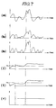
- the signal from the G sensor unit is filtered by the high pass filter 136 and supplied in the form of signal a (see trace (a) of the Fig. 7 timing chart) to the "powering" circuit 138 wherein the signal is self-multiplied one or more times (viz., one of squared, cubed, raised to the power 4 or greater). In this instance the signal is squared.
- the output of the "powering" circuit is supplied to the third integrator 140.
- the integrator 140 is arranged, along with the integrators 106 an 112, to be reset by the signal C assuming a low level (rendered active by the high level of signal C).
- an inverter can be inserted between the output of the flip flop 132 and the reset terminals of the just mentioned integrators.
- the output features a wave form of the nature shown in trace (I), while in the case of full wave rectification the output assumes the form shown in trace (I').
- the effect of the "powering" circuit is such as to attenuate the possibility that the output of the integrator does not hunt back and forth over the slice level and improves the accuracy of the damage accumulation prediction.
- the output (signal r) assumes a high level and sets the flip flop 144.
- the output of the slice level switch in case a squaring circuit is used is shown in solid line. In the case of a full wave rectifier, the output of the slice level switch is as shown in phantom.
- the deployment of the air-bag is controlled by the first and third sections of the system. That is to say, in the event that the level of deceleration which is induced by the collision does not exceed 4.0G level the output of the third comparator 120 remains at a low level and the second timer 126 is not triggered.
- the two timers 124, 126 are arranged so that the timing periods will overlap in the case of a collision of the nature wherein the vehicle has hit a pole or the like which is causing localized damage to the vehicle (viz., is "cutting" through the softer less rigid panels/structure of the vehicle body) and has not yet reached rigid structure (e.g. the engine/transmission, cabin bulkhead etc.,) and life endangering deceleration has not yet be produced.
- the output (I) of the integrator 140 exceeds the slice level of slice level switch 142 and has induced the output (J) of the flip flop 144 to assume a high level and thus cause the level of the OR gate 146 output (M) to go to a high level.
- the AND gate 148 induces the inflation of the air-bag AB.
- the output (G) of the fourth comparator 122 goes to high level and sets the flip flop 134.
- the flip flop 134 output remains at the high level until such time as the output (K) of the NOR gate 130 returns to a high level and resets the same.
- the flip flop 134 will be set and until both of the first and second timers 124, 126 have finished producing high level signals, the level of the OR gate output (M) will be assuredly held at a high level. This bypasses and/or supplements the operation of the third section SEC.03 of the system and provides a high level input (M) to the AND gate 148.
Description
- The invention relates to a passenger restraint device such as an air-bag as indicated in the precharacterizing part of
claim 1. - Fig. 1 shows a prior art air bag control circuit arrangement which is comprised of a
DC source 51, amalfunction inhibitor sensor 52detonators switches 55 and 56 connected in parallel. - The malfunction inhibitor switch can take the form of a mercury switch or the like which is responsive to vehicle motion and indicates if the vehicle is at standstill or not.
- With this arrangement, in the event of a collision, if the either of the
impact sensor switches 55 and 56 are closed (ON) at the same time as themalfunction inhibitor sensor 52 is ON, direct current is supplied from theDC source 51 to thedetonators - However, this arrangement suffers from the drawbacks that as the impact sensor switches 55 and 56 are of the mechanical type, they must precisely made (which increases the cost) and even when precisely manufactured tend not to provide the required level of reliability.
- To overcome these problems the arrangement shown in Fig. 2 has been proposed. This arrangement is such that the mechanical switch arrangement is replaced with a semi-conductor
type acceleration sensor 67, animpact discrimination circuit 68 and a switching arrangement generally denoted by thenumeral 613. In this instance theswitching arrangement 613 includes twoswitching transistors current sources detonators 63 and 64 in the illustrated manner. - The
impact discrimination circuit 68 is arranged to determine, based on the analog signal output by the acceleration sensor 7, if a collision which is apt to induced physical harm or death has occurred or not. In the event of an affirmative decision, thecircuit 68 applies a voltage to the gates of the switching transistors in a manner which render the same conductive (viz., ON). The fixedcurrent sources detonators 63 and 64 and thus induces the deployment of the air-bag or activation of the like type of restraining device. - However, this arrangement suffers from the drawback that, should the impact be of such a nature as to cause the section of wiring indicated by A, to be severed or the insulative wire coating removed in a manner which permits grounding to take place, even though the
switching transistors DC source 61 and thedetonators 63 and 64 has been cut or deteriorated to the point that neither can be ignited. This of course renders the air-bag or like type of restraint device inoperative. - On the other hand, in the event that the sections of wiring B and C between the
detonators 63, 64 and theswitching transistor malfunction inhibitor switch 62 assumes a closed (ON) condition (such as can be caused by vibration induced chatter), it becomes possible for direct current to flow through one or both of thedetonators - Fig. 3 shows another example of air bag control circuitry. This arrangement is disclosed in JP-A-49-55031. In this arrangement AB denotes an air-bag which is operatively connected with a impact detection type accelerometer or
G sensor 71 via a timing circuit arrangement. In this instance the timing circuit arrangement includes anamplifier 72; afirst comparator 74 which compares the output of the amplifier with a first predetermined slice level S1 and acts as a switch; anintegrator 76; a second slice level comparatortype switch circuit 78, and apulse generator 710 which is operatively connected with an ignitor orsquib 712. The latter mentioned element of course being used to detonate a charge which induces the required rapid gas generation. - With this arrangement, the output of the
G sensor 71 is amplified and produces a signal which contains a DC component. When this DC component containing signal exceeds the first slice level S1 incomparator 74, the device switches and the output is supplied to theintegrator 76 which integrates the DC component and supplies the result to thesecond comparator 78. When the integrated value exceeds a second slice level SK, thesecond comparator 78 switches and produces an output which is supplied to thepulse generator 710 which in turn induces the ignition of the air bag inflation charge. - Fig. 4 shows a second arrangement which is disclosed in the above mentioned document. In this arrangement an impact
sensing G sensor 814 is operatively connected with anamplifier 816. The output of theamplifier 816 is connected to a slice level switchtype circuit arrangement 818 which is arranged to output a signal in the event that the input exceeds a first slice level S1. A first integrator circuit 820 is operatively connected with the output terminals of both theamplifier 816 and the firstslice level switch 818. Asecond integrator 822 is operatively connected with the output terminal of the first integrator 820 and the output terminal of a second slice levelswitch type circuit 824 which is arranged, as shown, to receive the output of the first integrator 820. - A third slice level
switch circuit arrangement 826 is connected to the output of thesecond integrator 822 and arranged to compare the output thereof with a predetermined slice level VK. Upon the slice level being reached, the third slicelevel switch circuit 826 outputs a signal to apulse generator 828 which responds by inducing the ignition of an air bag inflation charge. - The arrangements shown in Figs. 3 and 4 suffer from the drawbacks that they are unable to adequately distinguish between accidents wherein the initial amount of damage is large and that wherein the initial damage is relatively small for a given period and then rapidly increases. Viz., in the case a vehicle collides directly against a solid wall and the deceleration to which the occupant is subjected increases rapidly, it is very easy to determine that deployment of an air bag is desirable.
- However, in the case wherein the vehicle collides with a pole (e.g. a steel light pole 30 - 40 cm in diameter) it is highly likely that the pole will "cut" through the paneling and less resilient components of the vehicle and for a given short time causing localized deformation of the bumper, front panels, radiator etc., before coming into contact with the engine or the like rigid structure which will produce very rapid deceleration. In this type of accident it is therefore highly likely that vehicular deceleration is apt to remain at relatively low levels while the pole "cuts" through the front of the vehicle and then suddenly increase to a magnitude sufficient to endanger the life of the driver and/or other occupants. This renders it very difficult to determine just when to deploy an air bag. If the bag inflated too early, it will tend to be deflating when the passenger comes into contact with the same and thus not be able to provide the required cushioning and passenger movement attenuation. On the other hand, if the inflation of the bag is delayed, it will not be fully inflated at the time the maximum cushioning effect is required.
- Therefore, there has hitherto been a demand for a highly reliable circuit which does not exhibit the tendency to produce erroneously timed activation trigger signals, which does not malfunction in response to wiring disconnections and the like, and which can be produced at a reasonable cost.
- Another prior art (US-A-4,975,850) passenger restraint system produces in accordance with an acceleration detector, a signal representing the existing condition of the vehicle. This condition signal is differentiated to produce a jerk signal. Only when the value of the condition signal exceeds a first threshold level a predetermined time period is timed. When the value of the jerk signal exceeds a jerk threshold level, a second signal is produced. Only when the second signal occurs during the predetermined time, a trigger signal is produced for actuating the restraint system. That is, a judgement is carried out as to whether or not the change rate or jerk of the vehicle acceleration is sufficient for actuating the restraint system. Consequently, also this prior art system cannot avoid generation of an erroneously timed activation trigger signal for the restraint device activating means.
- It is the object of the invention to provide a circuit arrangement which is able to accurately time the activation of an air bag or the like type of passenger restraint device.
- This object is solved by the features as claimed in
claim 1. - By means of the particular features of the cumulative damage discrimination circuit the ampount of damage which has occurred to the vehicle is predicted in response to the output of the acceleration sensing means
- Further developments of the invention are claimed in
sub-claims 2 to 5. - Prior art circuit arrangements and an embodiment of the invention are explained in detail in connection with the drawings.
- Figures 1 to 4 show the prior art circuit arrangements which were briefly discussed in the opening paragraphs of the present description,
- Figure 5 shows a block diagram of a circuit arrangement in a preferred embodiment of the invention, and
- Figures 6 and 7 are timing charts which depict the operation of the preferred embodiment.
- In the embodiment as shown in Figure 5 of the drawings an accelero-meter or
G sensor unit 100 is arranged to supply its output to a low pass filter (LPF) 102. The output ofLPF 102 is supplied to a first "displacement prediction" section SEC.01 of the system. This section comprises an ON/OFF type switch 103 and first and second serially connectedpartial integrators switch 103 is also connected with afirst coefficient circuit 108. Asecond coefficient circuit 110 is arranged to receive an input from a junction defined between the first andsecond integrators second integrator 106 and the first andsecond coefficient circuits adder circuit 112. A threshold level type comparator orslice level switch 114 is arranged to receive the output (N) of theadder 112 and to output a signal (O) upon a predetermined slice level being exceeded. - A second "G level" discrimination section SEC.02 of the system comprises first, second, third and
fourth comparators LPF 102 on their respective inputs. The second section further comprises first andsecond timer circuits OR gate 128, aNOR gate 130 and first and second multivibrator orflip flop circuits - In this instance the
first comparator 116 is arranged to compare the filtered output of the G sensor unit and determine if the voltage level is indicative of a force in excess of 1.0G. The output (A) of thefirst comparator 116 is connected with the set terminal (S) of the firstRS flip flop 132 and to the set terminal (S) of thefirst timer 124. Thefirst timer 124 is arranged to respond to the presence of a high level signal on its set terminal in a manner to be triggered in manner to generate a high level signal (D) on its output for 70ms (for example). - The
second comparator 118 is arranged to compare the filtered signal from the G sensor unit and determine if the voltage is indicative of an acceleration of more than 05.G. Thiscomparator 118, as different from the first one, is arranged to normally output a high level signal (B) and switch a low level one in the event that the 0.5G level is exceeded. The output (B) of thesecond comparator 118 is supplied to the reset terminals (R) of both of the first andsecond timer circuits OR gate 128. The output (L) of theOR gate 128 is connected with reset terminal (R) of the firstflip flop circuit 132. - The outputs (D, F) of the first and
second timers gate 130. The output (K) of the NOR 130 is supplied to the second of the input terminals of theOR 128. The set terminal (S) of thesecond timer 126 is arranged to receive the output (E) of thethird comparator 120. In this case thecomparator 120 is arranged to produce a high level output signal in the event that the output of the G sensor unit should indicate that the instant acceleration has reached or exceeded a 4.0G magnitude. - The
fourth comparator 122 is arranged to produce a high level in the event that the output of the G sensor unit is indicative of a 10.0G magnitude acceleration. The output (G) of thefourth comparator 122 is supplied to the set terminal of the secondflip flop circuit 134. - It will be noted that above 0.5, 1.0, 4.0 and 10.0G comparator settings are not fixed and can be changed to other values as required.
- A third so called "damage discrimination" section SEC.03 of the system comprises: a high pass filter HPF (or alternatively a band pass filter BPF) 136, a "powering" circuit 138 (viz., a circuit which one of squares, cubes etc., the input), an
integrator 140 and a threshold level comparator orslice level switch 142, all of which are connected in series. The output of theG sensor unit 100 is supplied to the input of the highpass filter HPF 136, while the output of theslice level switch 142 is supplied to the set terminal (R) of theflip flop 144. - An OR
gate 146 is connected to the output (Q) terminals of theflip flops gate 130 to receive the output (K) therefrom. - The outputs of the
slice level switch 114 and theOR gate 146 are supplied to the input terminals of an ANDgate 148. The output (P) of the AND 148 is supplied with anignition device 150 used to induce the inflation of an air-bag device AB. - In this system, the output (C) of the first flip flop circuit of the second section SEC.02 is used to open and close the
switch 103 and is also applied as a reset for the threeintegrators - It will be noted that it is within the scope of the present invention to connected the
first comparator 116 to theflip flop 132 by way of a delay circuit 151. The reason for this provision is to ensure that theflip flop 132 will be set after a reset has been carried out and remove the chance of two occurring at the same time or even in the wrong order, as might be apt to occur in the case of very rapid deceleration. - As pointed out above it is within the scope of the present invention to replace the high
pass filter HPF 136 with a band pass filter BPF; and/or alternatively replace the "powering"circuit 138 with a full wave rectification circuit. The effect of this latter mentioned replacement will become more clearly understood from the following discussion. - The operation of the above described system is such that when the vehicle is running normally along a road, signal C which is output by the
flip flop 132, assumes a low level and switch remains open (OFF) and the threeintegrators - Assume at this time that the output characteristics of the G sensor unit follow trace 1 (viz., characteristics wherein the G force exceeds the 1.0G level and then tapers off in a manner so as to not exceed the 4.0G level). Under these conditions, as the G value exceeds the 0.5 level the output (B) of the
second comparator 118 switches from a high level to a low one (see corresponding trace B in Fig. 6) This removes the signal which is constantly being applied to the reset terminals of thetimers gate 130 remains at a high level due to the outputs (D, F) of the twocounters OR gate 128 has assumed a low level the presence of high level signal (K) ensures that theflip flop circuit 132 remains in a reset state and thus holds the level of signal (C) applied to theswitch 103 at a low level. Thus, theswitch 103 remains open and the integrators are conditioned to assume a reset state. - Upon the output of the
G sensor unit 100 exceeding the 1.0G level, the output (A) of thefirst comparator 116 changes to a high level. This sets theflip flop 132 andfirst counter 124. At this time, as the output (D) oftimer 124 assumes a high level, the outputs (K, L) of the NOR 130 and OR 128 change to low levels. The high level signal (A) being applied to the set (S) terminal of thefirst flip flop 132 causes the output (C) thereof to assume a high level. This closesswitch 103 and enables theintegrators - Under these conditions the displacement prediction section SEC.01 is enabled and the
first integrator 104 converts the acceleration indicative signal into one indicative of velocity. Subsequently, thesecond integrator 106 converts the velocity signal into one indicative of displacement. At the same time the acceleration signal is processed in thefirst coefficient circuit 108 and converted into a signal indicative of displacement. Thesecond coefficient 110 circuit modifies the velocity signal in a manner which also converts the same into a displacement indicative one. - The three displacement signals which are produced by the
second integration circuit 106 and the first and secondcoefficient circuits 108 & 110, are supplied to theadder 112 which derives a signal indicative of the total displacement. This total displacement value is then supplied to the slicelevel switch circuit 114. - The signal from the G sensor unit is filtered by the
high pass filter 136 and supplied in the form of signal a (see trace (a) of the Fig. 7 timing chart) to the "powering"circuit 138 wherein the signal is self-multiplied one or more times (viz., one of squared, cubed, raised to thepower 4 or greater). In this instance the signal is squared. - It will be noted that this process produces an output having a wave form of the nature shown in trace (b) of Fig. 3. In the event of direct wave rectification is used in place of the squaring circuit the resulting signal exhibits the wave form depicted in trace (b').
- The output of the "powering" circuit is supplied to the
third integrator 140. It will be noted that theintegrator 140 is arranged, along with theintegrators 106 an 112, to be reset by the signal C assuming a low level (rendered active by the high level of signal C). Alternatively, an inverter can be inserted between the output of theflip flop 132 and the reset terminals of the just mentioned integrators. - In the event that the input to the
integrator 140 comes from a squaring circuit, the output features a wave form of the nature shown in trace (I), while in the case of full wave rectification the output assumes the form shown in trace (I'). - As will be appreciated, the effect of the "powering" circuit is such as to attenuate the possibility that the output of the integrator does not hunt back and forth over the slice level and improves the accuracy of the damage accumulation prediction.
- In the event that the integrated value exceeds the slice level of the
slice level switch 142, the output (signal r) assumes a high level and sets theflip flop 144. In Fig. 7(r) the output of the slice level switch in case a squaring circuit is used is shown in solid line. In the case of a full wave rectifier, the output of the slice level switch is as shown in phantom. - Setting of the
flip flop 144 of course induces the output (M) of theOR gate 146 thereof to assume a high level. When both of the outputs (O, M) of theslice level switch 114 and the OR gate assume high levels, the ANDgate 148 opens and the air-bag inflation charge is ignited. - It will be noted that in the event that the G force is determined to not exceed the 4.0G level, the deployment of the air-bag is controlled by the first and third sections of the system. That is to say, in the event that the level of deceleration which is induced by the collision does not exceed 4.0G level the output of the
third comparator 120 remains at a low level and thesecond timer 126 is not triggered. - It should be noted that the two
timers - Thus, in the case wherein the collision is such that the G force which is produced follows
trace 1 the second counter will not be triggered. On the other hand, if the characteristics of the collision are such that the deceleration produced followstrace 4, at the time the C force exceeds the 4.0G level, the operational events of the example depicted in the timing chart of Fig. 2 will occur. Viz., as shown, signals E and F output by thethird comparator 120 and thesecond timer 126 assume high levels. This is such as to maintain the output of the NORgate 130 at a low level past the point in time the output (D) of the first timer drops back to a low level. - In this particular example, slightly before the point in time the G force exceeds 4.0G the output (I) of the
integrator 140 exceeds the slice level ofslice level switch 142 and has induced the output (J) of theflip flop 144 to assume a high level and thus cause the level of theOR gate 146 output (M) to go to a high level. Thus, at the time the output (N) of theadder 112 exceeds the slice level of theswitch circuit 114, the ANDgate 148 induces the inflation of the air-bag AB. - It will be noted that at any time a G force of 10.0G or more, is sensed by the
G sensor unit 100, the output (G) of thefourth comparator 122 goes to high level and sets theflip flop 134. Theflip flop 134 output remains at the high level until such time as the output (K) of the NORgate 130 returns to a high level and resets the same. Thus, even though the G force level may remain above the 10.0G level for only a very short time, theflip flop 134 will be set and until both of the first andsecond timers gate 148. - As will be appreciated from trace (I) of Fig. 3, by setting the slice level Vth with which the output of the
third integrator 140 is compared, it is possible to induce the r signal to assume a high level at the timing indicated in solid line. - The setting of this slice level of course made in accordance with the type of vehicle and the structure of the same.
- Although the above embodiment is described as taking the form of an analog circuit arrangement, it will be understood that it can be readily implemented using appropriate software/programs in a microprocessor. In fact the use of a microprocessor facilitates the minor changes in settings which are required in order to adapt the same circuit to a number of different vehicles and facilitate the data input from various sensors such as those used passenger seat positions and the like.
Claims (5)
- A passenger vehicle restraint system comprising:
means (50) for activating a restraint device (AB);
acceleration sensor means (100) for sensing an acceleration and issuing an analog signal which represents the degree of said acceleration;
circuit means (SEC.01,SEC.02,SEC.03) responsive to said acceleration sensor means (100) for producing an activation trigger signal which is supplied to the restraint device activating means; and
a cumulative damage discrimination circuit (SEC.03) included in said circuit means, which senses the amount of energy produced when the vehicle encounters a collision by treating the analog signal from said acceleration sensor means (100) and issues a damage level signal upon the sensed energy amount exceeding a predetermined level,
characterized in that
said cumulative damage discrimination circuit (SEC.03) includes:
a powering circuit (138) for performing self-multiplication on the output from said acceleration sensor means (100) and producing a control signal; and
comparator means (142) for comparing the control signal produced by the powering circuit (138) with a predetermined level and issuing said damage level signal when the control signal exceeds the predetermined level. - A passenger vehicle restraint system as claimed in claim 1, further including a plurality of comparators (116,118,120,122), each comparator being responsive to a different impact level.
- A passenger vehicle restraint system as claimed in claim 2, in which the comparators (116,118,120,122) are connected in parallel.
- A passenger vehicle restraint system as claimed in claim 1, in which said circuit means further comprises:
an operation timing determination circuit (SEC.02) which determines the timing of operating the restraint device activating means (50) based on the displacement of the body of a passenger upon the vehicle collision, said operation timing determination circuit (SEC.02) being arranged in parallel with said cumulative damage discrimination circuit (SEC.03); and
an AND gate (148) to which the outputs of said cumulative damage discrimination circuit (SEC.03) and said operation timing determination circuit (SEC.02) are supplied, said AND gate (148) issuing an output supplied to the restraint device activating means (150). - A passenger vehicle restraint system as claimed in claim 1, in which said circuit means further comprises:
a displacement prediction discrimination circuit (SEC.01) which predicts the displacement of the body of a passenger upon vehicle collision, said displacement prediction discrimination circuit (SEC.01) being arranged in parallel with said cumulative damage discrimination curcuit (SEC.03); and
an AND gate (148) to which the outputs of said cumulative damage discrimination circuit (SEC.03) and said displacement prediction discrimination circuit are supplied, said AND gate (148) issuing an output supplied to the restraint device activating means (150).
Applications Claiming Priority (6)
| Application Number | Priority Date | Filing Date | Title |
|---|---|---|---|
| JP162401/91 | 1991-06-07 | ||
| JP3162401A JPH04362444A (en) | 1991-06-07 | 1991-06-07 | Vehicle occupant protection device |
| JP5797691U JPH0523752U (en) | 1991-06-28 | 1991-06-28 | Power circuit |
| JP57976/91U | 1991-06-28 | ||
| JP20458491 | 1991-07-22 | ||
| JP204584/91 | 1991-07-22 |
Publications (2)
| Publication Number | Publication Date |
|---|---|
| EP0517253A1 EP0517253A1 (en) | 1992-12-09 |
| EP0517253B1 true EP0517253B1 (en) | 1995-09-27 |
Family
ID=27296448
Family Applications (1)
| Application Number | Title | Priority Date | Filing Date |
|---|---|---|---|
| EP92109558A Expired - Lifetime EP0517253B1 (en) | 1991-06-07 | 1992-06-05 | Vehicle passenger restraint device for use in automotive vehicle or the like |
Country Status (3)
| Country | Link |
|---|---|
| US (1) | US5365114A (en) |
| EP (1) | EP0517253B1 (en) |
| DE (1) | DE69205067T2 (en) |
Families Citing this family (51)
| Publication number | Priority date | Publication date | Assignee | Title |
|---|---|---|---|---|
| US6532408B1 (en) * | 1997-05-29 | 2003-03-11 | Automotive Technologies International, Inc. | Smart airbag system |
| JP2793084B2 (en) * | 1992-05-29 | 1998-09-03 | 三菱電機株式会社 | Starting device for occupant protection device |
| JP2730853B2 (en) * | 1993-10-15 | 1998-03-25 | 富士通テン株式会社 | Airbag electronic control unit |
| JPH07186876A (en) * | 1993-12-27 | 1995-07-25 | Asuko Kk | Control device for safety device for vehicle |
| US5498028A (en) * | 1994-01-04 | 1996-03-12 | Trw Inc. | Method and apparatus for controlling an actuatable restraining device |
| JP2941643B2 (en) * | 1994-04-14 | 1999-08-25 | 三菱自動車工業株式会社 | Starting device for occupant protection device |
| DE4424551A1 (en) * | 1994-07-12 | 1996-01-18 | Autoliv Dev | Trip system for vehicle safety system with acceleration sensor |
| US5504379A (en) * | 1994-09-23 | 1996-04-02 | Trw Vehicle Safety Systems Inc. | Method and apparatus for sensing a vehicle crash using a velocity displacement metric |
| US5646454A (en) * | 1994-09-24 | 1997-07-08 | Robert Bosch Gmbh | Electronic safety device for vehicle occupants including a memory device for storing fault conditions and associated control commands |
| DE19520608A1 (en) * | 1995-06-06 | 1996-12-12 | Siemens Ag | Control arrangement for triggering a restraint in a vehicle in the event of a side impact |
| DE19531899B4 (en) * | 1995-08-30 | 2004-11-25 | Robert Bosch Gmbh | Electronic setup and operating procedures for this |
| JP2973902B2 (en) * | 1995-11-06 | 1999-11-08 | トヨタ自動車株式会社 | Activation control device for occupant protection device |
| US5907198A (en) * | 1996-03-05 | 1999-05-25 | Molex Incorporated | Trickle power supply |
| DE19619412C1 (en) * | 1996-05-14 | 1997-08-28 | Telefunken Microelectron | Triggering passive safety device for occupant of vehicle in crash |
| DE19619414C1 (en) * | 1996-05-14 | 1997-08-21 | Telefunken Microelectron | Passive passenger restraint e.g. airbag release control method for vehicle |
| US6070113A (en) * | 1996-06-21 | 2000-05-30 | Automotive Systems Laboratory, Inc. | Hybrid vehicle crash discrimination system |
| DE19625004A1 (en) * | 1996-06-22 | 1998-01-08 | Daimler Benz Ag | Trigger circuit for an occupant restraint system |
| US6023664A (en) * | 1996-10-16 | 2000-02-08 | Automotive Systems Laboratory, Inc. | Vehicle crash sensing system |
| DE19645079A1 (en) * | 1996-10-31 | 1998-05-07 | Siemens Ag | Control arrangement for an occupant protection system for side impact protection in a vehicle |
| JP3405173B2 (en) * | 1998-02-18 | 2003-05-12 | トヨタ自動車株式会社 | Ignition control method for vehicle occupant protection device |
| DE19815002C2 (en) * | 1998-04-03 | 2003-10-23 | Bosch Gmbh Robert | Method for determining control data for triggering restraint devices in a vehicle |
| US6272412B1 (en) | 1998-11-09 | 2001-08-07 | Ford Global Technologies, Inc. | Passive restraint control system for vehicles |
| US6731023B2 (en) | 2001-03-29 | 2004-05-04 | Autoliv Asp, Inc. | Backup power supply for restraint control module |
| US20050108065A1 (en) * | 2003-11-18 | 2005-05-19 | Dorfstatter Walter A. | Method and system of estimating vehicle damage |
| JP4569114B2 (en) * | 2004-01-28 | 2010-10-27 | 株式会社デンソー | Occupant protection system and determination device |
| KR100755391B1 (en) * | 2005-04-18 | 2007-09-04 | 주식회사 일진글로벌 | Apparatus of Driving Safety Control for Automobile |
| US20070168097A1 (en) * | 2006-01-18 | 2007-07-19 | Automotive Systems Laboratory, Inc. | Discrete hardware safing circuit |
| US9067565B2 (en) | 2006-05-22 | 2015-06-30 | Inthinc Technology Solutions, Inc. | System and method for evaluating driver behavior |
| US8630768B2 (en) | 2006-05-22 | 2014-01-14 | Inthinc Technology Solutions, Inc. | System and method for monitoring vehicle parameters and driver behavior |
| US7899610B2 (en) | 2006-10-02 | 2011-03-01 | Inthinc Technology Solutions, Inc. | System and method for reconfiguring an electronic control unit of a motor vehicle to optimize fuel economy |
| JP4636007B2 (en) * | 2006-11-14 | 2011-02-23 | いすゞ自動車株式会社 | Collision safety control device |
| US8825277B2 (en) * | 2007-06-05 | 2014-09-02 | Inthinc Technology Solutions, Inc. | System and method for the collection, correlation and use of vehicle collision data |
| US8666590B2 (en) | 2007-06-22 | 2014-03-04 | Inthinc Technology Solutions, Inc. | System and method for naming, filtering, and recall of remotely monitored event data |
| US9129460B2 (en) | 2007-06-25 | 2015-09-08 | Inthinc Technology Solutions, Inc. | System and method for monitoring and improving driver behavior |
| US7999670B2 (en) | 2007-07-02 | 2011-08-16 | Inthinc Technology Solutions, Inc. | System and method for defining areas of interest and modifying asset monitoring in relation thereto |
| US9117246B2 (en) | 2007-07-17 | 2015-08-25 | Inthinc Technology Solutions, Inc. | System and method for providing a user interface for vehicle mentoring system users and insurers |
| US8577703B2 (en) | 2007-07-17 | 2013-11-05 | Inthinc Technology Solutions, Inc. | System and method for categorizing driving behavior using driver mentoring and/or monitoring equipment to determine an underwriting risk |
| US8818618B2 (en) | 2007-07-17 | 2014-08-26 | Inthinc Technology Solutions, Inc. | System and method for providing a user interface for vehicle monitoring system users and insurers |
| US7876205B2 (en) | 2007-10-02 | 2011-01-25 | Inthinc Technology Solutions, Inc. | System and method for detecting use of a wireless device in a moving vehicle |
| US8688180B2 (en) | 2008-08-06 | 2014-04-01 | Inthinc Technology Solutions, Inc. | System and method for detecting use of a wireless device while driving |
| US8963702B2 (en) | 2009-02-13 | 2015-02-24 | Inthinc Technology Solutions, Inc. | System and method for viewing and correcting data in a street mapping database |
| US8188887B2 (en) | 2009-02-13 | 2012-05-29 | Inthinc Technology Solutions, Inc. | System and method for alerting drivers to road conditions |
| US8892341B2 (en) | 2009-02-13 | 2014-11-18 | Inthinc Technology Solutions, Inc. | Driver mentoring to improve vehicle operation |
| CN105974571B (en) | 2009-10-28 | 2019-05-28 | 阿兰蒂克微科学股份有限公司 | Micro-imaging |
| US9075225B2 (en) | 2009-10-28 | 2015-07-07 | Alentic Microscience Inc. | Microscopy imaging |
| US20140100710A1 (en) * | 2012-10-05 | 2014-04-10 | Ford Global Technologies | Method and system for determining a primary direction of force resulting from a vehicle collision |
| US9162642B2 (en) | 2012-10-05 | 2015-10-20 | Ford Global Technologies | Method and system for determining a primary direction of force resulting from a vehicle collision |
| US10502666B2 (en) | 2013-02-06 | 2019-12-10 | Alentic Microscience Inc. | Sample processing improvements for quantitative microscopy |
| EP3014330B1 (en) | 2013-06-26 | 2024-01-03 | Alentic Microscience Inc. | Sample processing improvements for microscopy |
| US9172477B2 (en) | 2013-10-30 | 2015-10-27 | Inthinc Technology Solutions, Inc. | Wireless device detection using multiple antennas separated by an RF shield |
| US11034318B2 (en) * | 2019-06-04 | 2021-06-15 | B/E Aerospace, Inc. | Safety system initiator with electronically adjustable fire time |
Family Cites Families (11)
| Publication number | Priority date | Publication date | Assignee | Title |
|---|---|---|---|---|
| US3714627A (en) * | 1971-10-20 | 1973-01-30 | Gen Motors Corp | Vehicle inflatable cushion actuation and monitoring circuit |
| DE2222038C3 (en) * | 1972-05-05 | 1978-07-06 | Messerschmitt-Boelkow-Blohm Gmbh, 8000 Muenchen | Test circuit for the triggering device of a safety device used to protect the occupants of a vehicle during an accident |
| JPS5636093B2 (en) * | 1973-03-16 | 1981-08-21 | ||
| DE3816587A1 (en) * | 1988-05-16 | 1989-11-23 | Messerschmitt Boelkow Blohm | DEVICE FOR TRIGGERING A PASSIVE SAFETY DEVICE |
| JPH0735142B2 (en) * | 1988-05-24 | 1995-04-19 | 日本電装株式会社 | Failure determination device for vehicle occupant protection system |
| EP0434678B2 (en) * | 1988-09-14 | 1998-08-19 | Robert Bosch Gmbh | Air bag system for protection of the occupants of motor vehicles |
| US4958851A (en) * | 1989-05-01 | 1990-09-25 | Automotive Systems Laboratory, Inc. | Air bag firing circuit |
| US5040118A (en) * | 1989-11-06 | 1991-08-13 | Trw Technar Inc. | Apparatus and method employing multiple crash evaluation algorithms and evaluation expertise for actuating a restraint system in a passenger vehicle |
| US4990884A (en) * | 1989-12-12 | 1991-02-05 | Trw Inc. | Method and apparatus for testing an airbag restraint system |
| US5187465A (en) * | 1990-09-27 | 1993-02-16 | Trw Inc. | Method and apparatus for testing a dual airbag passive restraint system |
| US5261694A (en) * | 1991-06-14 | 1993-11-16 | Automotive Systems Laboratory, Inc. | Reconfigurable air bag firing circuit |
-
1992
- 1992-06-05 EP EP92109558A patent/EP0517253B1/en not_active Expired - Lifetime
- 1992-06-05 DE DE69205067T patent/DE69205067T2/en not_active Expired - Fee Related
- 1992-06-08 US US07/894,968 patent/US5365114A/en not_active Expired - Lifetime
Also Published As
| Publication number | Publication date |
|---|---|
| DE69205067T2 (en) | 1996-03-21 |
| EP0517253A1 (en) | 1992-12-09 |
| DE69205067D1 (en) | 1995-11-02 |
| US5365114A (en) | 1994-11-15 |
Similar Documents
| Publication | Publication Date | Title |
|---|---|---|
| EP0517253B1 (en) | Vehicle passenger restraint device for use in automotive vehicle or the like | |
| US5787377A (en) | Air-bag control circuit | |
| JP2619980B2 (en) | Actuating device for passenger restraint device for operating passenger restraint device of passenger car in response to vehicle jerk and method of operating the same | |
| AU695023B2 (en) | Airbag deployment control apparatus for vehicle and the method | |
| US5587906A (en) | Method and apparatus for sensing a vehicle crash condition using velocity enhanced acceleration crash metrics | |
| US5749059A (en) | Apparatus and method for controlling an actuatable restraint device | |
| US4243248A (en) | Air bag system for the protection of the passengers of motor vehicles in case of accidents | |
| US6271747B1 (en) | Method for adjusting the trigger threshold of vehicle occupant protection devices | |
| US5081587A (en) | Control system for actuating vehicle safety devices | |
| US5546307A (en) | Method and apparatus for discriminating vehicle crash conditions | |
| JP2744170B2 (en) | Modifiable airbag ignition circuit | |
| US6125313A (en) | Air-bag control circuit | |
| JPS63503531A (en) | Passenger protection device activation device | |
| KR100521856B1 (en) | Activation control unit and control method thereof for occupant protection apparatus | |
| JPH08230610A (en) | Pedestrian protective device | |
| US5879024A (en) | Air bag deployment inhibitor circuit | |
| US5129673A (en) | Electronic device | |
| US20080172158A1 (en) | Air-bag deployment system | |
| JPH07251701A (en) | Method and device for controlling actuatable protective device | |
| US6109648A (en) | Control unit for an occupant restraint system using adaptive triggering threshold | |
| US5170066A (en) | Single-sensing airbag system with zero power consumption in the "key-off" st | |
| Chan | A treatise on crash sensing for automotive air bag systems | |
| JPH0796816A (en) | Electronic airbag device | |
| JP3633107B2 (en) | Airbag device | |
| JPH04252758A (en) | Collision judgement circuit |
Legal Events
| Date | Code | Title | Description |
|---|---|---|---|
| PUAI | Public reference made under article 153(3) epc to a published international application that has entered the european phase |
Free format text: ORIGINAL CODE: 0009012 |
|
| 17P | Request for examination filed |
Effective date: 19920605 |
|
| AK | Designated contracting states |
Kind code of ref document: A1 Designated state(s): DE FR GB SE |
|
| 17Q | First examination report despatched |
Effective date: 19940509 |
|
| GRAA | (expected) grant |
Free format text: ORIGINAL CODE: 0009210 |
|
| STAA | Information on the status of an ep patent application or granted ep patent |
Free format text: STATUS: THE PATENT HAS BEEN GRANTED |
|
| AK | Designated contracting states |
Kind code of ref document: B1 Designated state(s): DE FR GB SE |
|
| REF | Corresponds to: |
Ref document number: 69205067 Country of ref document: DE Date of ref document: 19951102 |
|
| ET | Fr: translation filed | ||
| PLBE | No opposition filed within time limit |
Free format text: ORIGINAL CODE: 0009261 |
|
| 26N | No opposition filed | ||
| EUG | Se: european patent has lapsed | ||
| REG | Reference to a national code |
Ref country code: GB Ref legal event code: IF02 |
|
| PGFP | Annual fee paid to national office [announced via postgrant information from national office to epo] |
Ref country code: GB Payment date: 20060531 Year of fee payment: 15 |
|
| PGFP | Annual fee paid to national office [announced via postgrant information from national office to epo] |
Ref country code: DE Payment date: 20060601 Year of fee payment: 15 |
|
| PGFP | Annual fee paid to national office [announced via postgrant information from national office to epo] |
Ref country code: SE Payment date: 20060607 Year of fee payment: 15 |
|
| PGFP | Annual fee paid to national office [announced via postgrant information from national office to epo] |
Ref country code: FR Payment date: 20060608 Year of fee payment: 15 |
|
| EUG | Se: european patent has lapsed | ||
| GBPC | Gb: european patent ceased through non-payment of renewal fee |
Effective date: 20070605 |
|
| REG | Reference to a national code |
Ref country code: FR Ref legal event code: ST Effective date: 20080229 |
|
| PG25 | Lapsed in a contracting state [announced via postgrant information from national office to epo] |
Ref country code: DE Free format text: LAPSE BECAUSE OF NON-PAYMENT OF DUE FEES Effective date: 20080101 |
|
| PG25 | Lapsed in a contracting state [announced via postgrant information from national office to epo] |
Ref country code: GB Free format text: LAPSE BECAUSE OF NON-PAYMENT OF DUE FEES Effective date: 20070605 |
|
| PG25 | Lapsed in a contracting state [announced via postgrant information from national office to epo] |
Ref country code: SE Free format text: LAPSE BECAUSE OF NON-PAYMENT OF DUE FEES Effective date: 20070606 |
|
| PG25 | Lapsed in a contracting state [announced via postgrant information from national office to epo] |
Ref country code: FR Free format text: LAPSE BECAUSE OF NON-PAYMENT OF DUE FEES Effective date: 20070702 |