EP0529795A1 - Magnetooptic recording medium - Google Patents
Magnetooptic recording medium Download PDFInfo
- Publication number
- EP0529795A1 EP0529795A1 EP92306650A EP92306650A EP0529795A1 EP 0529795 A1 EP0529795 A1 EP 0529795A1 EP 92306650 A EP92306650 A EP 92306650A EP 92306650 A EP92306650 A EP 92306650A EP 0529795 A1 EP0529795 A1 EP 0529795A1
- Authority
- EP
- European Patent Office
- Prior art keywords
- layer
- layers
- medium according
- recording
- rare earth
- Prior art date
- Legal status (The legal status is an assumption and is not a legal conclusion. Google has not performed a legal analysis and makes no representation as to the accuracy of the status listed.)
- Granted
Links
Images
Classifications
-
- G—PHYSICS
- G11—INFORMATION STORAGE
- G11B—INFORMATION STORAGE BASED ON RELATIVE MOVEMENT BETWEEN RECORD CARRIER AND TRANSDUCER
- G11B11/00—Recording on or reproducing from the same record carrier wherein for these two operations the methods are covered by different main groups of groups G11B3/00 - G11B7/00 or by different subgroups of group G11B9/00; Record carriers therefor
- G11B11/10—Recording on or reproducing from the same record carrier wherein for these two operations the methods are covered by different main groups of groups G11B3/00 - G11B7/00 or by different subgroups of group G11B9/00; Record carriers therefor using recording by magnetic means or other means for magnetisation or demagnetisation of a record carrier, e.g. light induced spin magnetisation; Demagnetisation by thermal or stress means in the presence or not of an orienting magnetic field
- G11B11/105—Recording on or reproducing from the same record carrier wherein for these two operations the methods are covered by different main groups of groups G11B3/00 - G11B7/00 or by different subgroups of group G11B9/00; Record carriers therefor using recording by magnetic means or other means for magnetisation or demagnetisation of a record carrier, e.g. light induced spin magnetisation; Demagnetisation by thermal or stress means in the presence or not of an orienting magnetic field using a beam of light or a magnetic field for recording by change of magnetisation and a beam of light for reproducing, i.e. magneto-optical, e.g. light-induced thermomagnetic recording, spin magnetisation recording, Kerr or Faraday effect reproducing
- G11B11/10582—Record carriers characterised by the selection of the material or by the structure or form
- G11B11/10584—Record carriers characterised by the selection of the material or by the structure or form characterised by the form, e.g. comprising mechanical protection elements
-
- G—PHYSICS
- G11—INFORMATION STORAGE
- G11B—INFORMATION STORAGE BASED ON RELATIVE MOVEMENT BETWEEN RECORD CARRIER AND TRANSDUCER
- G11B11/00—Recording on or reproducing from the same record carrier wherein for these two operations the methods are covered by different main groups of groups G11B3/00 - G11B7/00 or by different subgroups of group G11B9/00; Record carriers therefor
- G11B11/10—Recording on or reproducing from the same record carrier wherein for these two operations the methods are covered by different main groups of groups G11B3/00 - G11B7/00 or by different subgroups of group G11B9/00; Record carriers therefor using recording by magnetic means or other means for magnetisation or demagnetisation of a record carrier, e.g. light induced spin magnetisation; Demagnetisation by thermal or stress means in the presence or not of an orienting magnetic field
- G11B11/105—Recording on or reproducing from the same record carrier wherein for these two operations the methods are covered by different main groups of groups G11B3/00 - G11B7/00 or by different subgroups of group G11B9/00; Record carriers therefor using recording by magnetic means or other means for magnetisation or demagnetisation of a record carrier, e.g. light induced spin magnetisation; Demagnetisation by thermal or stress means in the presence or not of an orienting magnetic field using a beam of light or a magnetic field for recording by change of magnetisation and a beam of light for reproducing, i.e. magneto-optical, e.g. light-induced thermomagnetic recording, spin magnetisation recording, Kerr or Faraday effect reproducing
- G11B11/10582—Record carriers characterised by the selection of the material or by the structure or form
- G11B11/10586—Record carriers characterised by the selection of the material or by the structure or form characterised by the selection of the material
-
- Y—GENERAL TAGGING OF NEW TECHNOLOGICAL DEVELOPMENTS; GENERAL TAGGING OF CROSS-SECTIONAL TECHNOLOGIES SPANNING OVER SEVERAL SECTIONS OF THE IPC; TECHNICAL SUBJECTS COVERED BY FORMER USPC CROSS-REFERENCE ART COLLECTIONS [XRACs] AND DIGESTS
- Y10—TECHNICAL SUBJECTS COVERED BY FORMER USPC
- Y10S—TECHNICAL SUBJECTS COVERED BY FORMER USPC CROSS-REFERENCE ART COLLECTIONS [XRACs] AND DIGESTS
- Y10S428/00—Stock material or miscellaneous articles
- Y10S428/922—Static electricity metal bleed-off metallic stock
- Y10S428/9265—Special properties
- Y10S428/928—Magnetic property
-
- Y—GENERAL TAGGING OF NEW TECHNOLOGICAL DEVELOPMENTS; GENERAL TAGGING OF CROSS-SECTIONAL TECHNOLOGIES SPANNING OVER SEVERAL SECTIONS OF THE IPC; TECHNICAL SUBJECTS COVERED BY FORMER USPC CROSS-REFERENCE ART COLLECTIONS [XRACs] AND DIGESTS
- Y10—TECHNICAL SUBJECTS COVERED BY FORMER USPC
- Y10T—TECHNICAL SUBJECTS COVERED BY FORMER US CLASSIFICATION
- Y10T428/00—Stock material or miscellaneous articles
- Y10T428/12—All metal or with adjacent metals
- Y10T428/12465—All metal or with adjacent metals having magnetic properties, or preformed fiber orientation coordinate with shape
-
- Y—GENERAL TAGGING OF NEW TECHNOLOGICAL DEVELOPMENTS; GENERAL TAGGING OF CROSS-SECTIONAL TECHNOLOGIES SPANNING OVER SEVERAL SECTIONS OF THE IPC; TECHNICAL SUBJECTS COVERED BY FORMER USPC CROSS-REFERENCE ART COLLECTIONS [XRACs] AND DIGESTS
- Y10—TECHNICAL SUBJECTS COVERED BY FORMER USPC
- Y10T—TECHNICAL SUBJECTS COVERED BY FORMER US CLASSIFICATION
- Y10T428/00—Stock material or miscellaneous articles
- Y10T428/12—All metal or with adjacent metals
- Y10T428/12493—Composite; i.e., plural, adjacent, spatially distinct metal components [e.g., layers, joint, etc.]
- Y10T428/12632—Four or more distinct components with alternate recurrence of each type component
-
- Y—GENERAL TAGGING OF NEW TECHNOLOGICAL DEVELOPMENTS; GENERAL TAGGING OF CROSS-SECTIONAL TECHNOLOGIES SPANNING OVER SEVERAL SECTIONS OF THE IPC; TECHNICAL SUBJECTS COVERED BY FORMER USPC CROSS-REFERENCE ART COLLECTIONS [XRACs] AND DIGESTS
- Y10—TECHNICAL SUBJECTS COVERED BY FORMER USPC
- Y10T—TECHNICAL SUBJECTS COVERED BY FORMER US CLASSIFICATION
- Y10T428/00—Stock material or miscellaneous articles
- Y10T428/12—All metal or with adjacent metals
- Y10T428/12493—Composite; i.e., plural, adjacent, spatially distinct metal components [e.g., layers, joint, etc.]
- Y10T428/12771—Transition metal-base component
- Y10T428/12861—Group VIII or IB metal-base component
- Y10T428/12875—Platinum group metal-base component
Definitions
- the invention relates to a magnetooptic recording medium for recording and/or reproducing information by a laser beam or the like by utilizing a magneto-optical effect and, more particularly, to a magnetooptic recording medium of an artificial lattice film system having a good vertical magnetic anisotropy and a high coercive force.
- an amorphous alloy comprising a combination of rare earth element such as Gd, Tb, Dy, or the like and a transition metal element such as Fe, Co, or the like.
- a transition metal element such as Fe, Co, or the like.
- a recording material of the Co-Pt system or Co-Pd system using a platinum group metal such as Pt, Pd, or the like in place of the rare earth element has an excellent corrosion resistance.
- Techniques for raising the coercive force by using those systems as artificial lattice films are disclosed in JP-A-1-98144, JP-A-1-162257, and the like.
- a coercive force of about 100 to 200 Oe is obtained in case of the artificial lattice film of the Co-Pt system and a coercive force of about 500 to 2000 Oe is obtained in case of the artificial lattice film of the Co-Pd system, so that vertical magnetic films are realized.
- the artificial lattice film is what is called a super lattice film or modulation structural film and is a film in which a plurality of layers which are made of different components and have a thickness of several tens of atomic layers or less are regularly repetitively laminated so as to each have a predetermined thickness.
- the conventional magnetooptic recording medium using the foregoing artificial lattice film as a recording layer has a problem such that a magnitude of the coercive force of the recording layer and a magnitude of the vertical magnetic anisotropy are still insufficient to stably execute a magnetooptic recording.
- a magnetooptic recording medium comprising a substrate and a recording layer which is provided on the substrate and is formed by periodically laminating a plurality of fundamental units, wherein each of the fundamental units is constructed by: a first layer made of Co; a second layer made of a material selected from Pt, Pd, and Pt-Pd alloy; a third layer made of Co; and a fourth layer made of one or more kinds of elements selected from Ce, Pr, Nd, Pm, Sm, Eu, Gd, Tb, Dy, Ho, and Er.
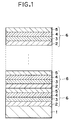
- Fig. 1 is a cross sectional view of an example of a magnetooptic recording medium based on the invention.
- the magnetooptic recording medium shown here is constructed in a manner such that a fundamental unit 6 is formed by sequentially laminating a first Co layer 2 made of Co, a platinum group layer 3 made of a metal selected from Pt, Pd, and Pt-Pd alloy, a second Co layer 4 made of Co, and a rare earth layer 5, an artificial lattice film is formed by repetitively regularly laminating such a fundamental unit 6 a number of times, and the artificial lattice film is used as a recording layer.
- the recording layer is provided on a substrate 1 made of a glass, plastics, or the like.
- the rare earth layer 5 is made of at least one or more kinds of elements selected from Ce, Pr, Nd, Pm, Sm, Eu, Gd, Tb, Dy, Ho, and Er.
- first and second Co layers 2 and 4 are now desirable to set thicknesses of first and second Co layers 2 and 4 to values of about 2 to 30 ⁇ , to set a thickness of platinum group layer 3 to a value of about 3 to 40 ⁇ , and to set a thickness of rare earth layer 5 to a value of about 2 to 30 ⁇ . It is desirable that a thickness of artificial lattice film which has finally been laminated, namely, recording layer is set to a value of about 50 to 800 ⁇ .
- each interface constructing the above artificial lattice film namely, the interfaces among the first and second co layers 2 and 4 and the platinum group layer 3 and the interfaces among the first and second Co layers 2 and 4 and the rare earth layer are flat without mutually mixing the atoms in the layers on both sides.
- a composition modulation structure such that the compositions fluctuate while keeping a predetermined period as a whole although slight disturbances occur in the interfaces.
- the above artificial lattice film can be formed by sputtering, vacuum evaporation deposition, molecular beam epitaxy (MBE), or the like.
- various kinds of elements can be also added in order to raise a thermal stability, to change a Curie temperature, or the like.
- an element to be added into each of the Co layers it is preferable to use at least one kind selected from b, C, Al, Si, P, Ti, V, Fe, Ni, Cu, Ga, Zr, Nb, Mo, In, Sn, and Sb.
- elements which are added into the platinum layer in addition to the elements similar to those in each Co layer, there can be mentioned Cr, Mn, Co, Zn, Y, Rh, Ag, La, Nd, Sm, Eu, Ho, Hf, W, Ir, Au, Pb, Bi, and the like.
- the recording layer is generally formed on a transparent substrate.
- protecting layers using a metal, a semimetal, a semiconductor, or a dielectric material can be provided on both sides of the recording layer.
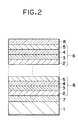
- Fig. 2 is a schematic cross sectional view showing the second embodiment of the invention in which such protecting layers are provided.
- Fig. 2 the same component elements as those shown in Fig. 1 are designated by the same reference numerals and their detailed descriptions are omitted here.
- the second embodiment differs from the first embodiment with respect to a point that a first protecting layer 7 is provided between a recording layer which is constructed by periodically laminating a fundamental unit 6 and the substrate 1 and a second protecting layer 8 is provided on the recording layer.
- a metal, a dielectric material, a semimetal, a semiconductor, or the like can be used as materials of the protecting layers 7 and 8.
- a metal material When a metal material is used as protecting layers, it is preferable to provide a film having a thickness of 5 to 500 ⁇ and made of Cu, Rh, Pd, Ag, Ir, Pt, or Au having a face-centered cubic structure or a film having a thickness of 5 to 500 ⁇ and made of W or the like having a body-centered cubic structure.
- an oxide system compound such as Al2O3, Ta2O5, MgO, SiO2, Fe2O3, ZrO2, Bi2O3, or the like
- a nitride system compound such as ZrN, TiN, Si3N4, AlN, AlSiN, BN, TaN, NbN, or the like, etc.
- a semimetal or a semiconductor it is desirable to provide a film having a thickness of 5 to 5000 ⁇ and made of Si, Ge, ZnSe, SiC, ZnS, or the like.
- a layer having a high reflectance can be also provided.
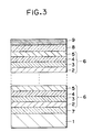
- Fig. 3 is a schematic cross sectional view showing the third embodiment of the invention having such protecting layers.
- the same component elements as those shown in Fig. 2 are designated by the same reference numerals and their detailed descriptions are omitted here.
- the third embodiment differs from the second embodiment with respect to a point that a reflecting layer 9 is further provided on the second protecting layer 8.
- a reflecting layer 9 is further provided on the second protecting layer 8.
- the recording layer is formed by a super thin film of 200 ⁇ or less
- most of the incident light is transmitted through the recording layer.
- the light for recording and reading out enters from the side of the substrate made of a transparent material, by providing the reflecting layer on the side opposite to the recording layer when it is seen from the substrate side, the magneto-optical effect of the light which is transmitted through the recording layer can be sufficiently used.
- a proper metal can be used as such a reflecting layer.
- a structure which is formed by sequentially laminating the first Co layer, platinum group layer, second Co layer, and rare earth layer as mentioned above is used as a fundametnal unit.
- An artificial lattice film is formed by laminating a plurality of such fundamental units.
- a magnetooptic recording medium is formed by using such an artificial lattice film.
- such a magnetooptic recording medium has a large coercive force and a larger vertical magnetic anisotropy in a wide film forming range as compared with those of the conventional artificial lattice film of the Pt-Co system or Pd-Co system.
- Targets of Co, Pt, and Tb each having a diameter of 3 inches are arranged in a magnetron sputtering apparatus, respectively.
- Slide glass substrate is arranged at the position which faces those targets.
- the sputtering is executed under an Ar partial pressure and a condition of a gas pressure of 8 mTorr, thereby forming recording layers made of artificial lattice films onto the slide glass substrate as shown hereinbelow.
- Samples (Examples 1-1 to 1-4) of the magnetooptic recording medium are formed.
- Sputtering processes are simultaneously performed under conditions such that a DC electric power of 0.1A - 300V is applied to the Co target (first target) and a DC electric power of 0.15A - 300V is applied to the Pt target (second target) and a high frequency electric power of 25W is applied to the Tb target (third target).
- a DC electric power of 0.1A - 300V is applied to the Co target (first target) and a DC electric power of 0.15A - 300V is applied to the Pt target (second target) and a high frequency electric power of 25W is applied to the Tb target (third target).
- artificial lattice films using fundamental units each comprising the first to fourth layers are formed on the slide glass substrates.
- the first layer corresponds to the first Co layer.
- the second layer corresponds to the platinum group layer.
- the third layer corresponds to the second Co layer.
- the fourth layer corresponds to the rare earth layer. Film thicknesses of those first to fourth layers and a total film thickness of the artificial lattice
- a saturation magnetization (emu/cc), a coercive force (kOe), a magnetic field (kOe) which is necessary to magnetize and saturate in the direction perpendicular to the film surface, and a Kerr rotational angle (°) from the artificial lattice film surface of each of the samples obtained are measured by using a magnetization measuring device (VSM) of the sample vibrating type and a Kerr effect measuring device using a laser beam of a wavelength of 830 nm.
- VSM magnetization measuring device
- Comparison examples 1-1 to 1-3 An artificial lattice film using a fundamental unit comprising only the first and second layers is formed and samples of the magnetooptic recording medium are formed as Comparison examples 1-1 to 1-3. These Comparison examples correspond to the magnetooptic recording media each of which is made of the conventional artificial lattice film (fundamental unit comprises two layers) of the Co-Pt system. Various kinds of magnetic characteristics are also similarly measured with respect to Comparison examples 1-1 to 1-3. The results are shown in Table 1.
- Samples (Examples 2-1 and 2-2 and Comparison examples 2-1 to 2-7) are formed in a manner similar to Example 1 and Comparison example 1 while changing the materials which are arranged for the targets, film thicknesses of layers, and the like as shown in Table 2.
- the samples formed are also evaluated in a manner similar to Example 1 and Comparison example 1 mentioned above.
- the results are also shown in Table 2.
- "in-plane” in “Remarks” in Table 2 denotes that the sample becomes an in-plane magnetic anisotropic film.
- the fundamental unit comprises four layers and has a construction of the magnetooptic recording medium of the invention.
- the fundamental unit comprises two or three layers and those samples are out of the purview of the invention.
- Comparison examples 2-3 and 2-4 relate to the samples in which rare earth elements which are used in the invention are added to the Co layer of the conventional artificial lattice film of the Co-Pd system.
- the samples of Comparison examples 2-3 and 2-4 are the in-plane anisotropic films.
- Comparison examples 2-5 and 2-6 are formed by adding rare earth elements which are used in the invention into the Pd layer of the conventional artificial lattice film of the Co-Pd system and become the in-plane anisotropic films.
- the fundamental unit of the artificial lattice film comprises three layers which are formed by sequentially laminating the Co layer, platinum group layer, and rare earth layer.
- the sample of comparison example 2-7 is also the in-plane magnetic anisotropic film.
- the reason why the conventional artificial lattice films of the Co-Pt system and Co-Pd system exhibit the vertical magnetic anisotropy is because the film depends on an influence force such as coupling between the atoms in the interface between the Co layer and the Pt or Pd layer, stress distortion in the interface, or the like. It is also known that when a rare earth element is mixed into either one of the layers constructing the conventional artificial lattice film of the Co-Pt system or Co-Pd system or when an intermediate layer made of a rare earth element is inserted between the Co layer and the Pt or Pd layer, the vertical magnetic anisotropy is extinguished. The above phenomena are also shown and will be understood from the results of Comparison examples mentioned above. On the other hand, it is also know that the super thin multi-layer film comprising the Co layer and the rare earth atom layer exhibits a good vertical magnetic anisotropy due to the couplirig between the atoms similar to that mentioned above.
- the Co layer and the platinum group layer construct one pair and the Co layer and the rare earth layer also construct another pair. It is expected that a good vertical magnetic anisotropy is obtained without obstructing the vertical magnetic anisotropy which each pair has. As shown in above Examples, a good vertical magnetic anisotropy can be actually obtained.
- the fundamental unit is formed by sequentially laminating the first Co layer made of Co, platinum group layer made of metal selected from Pt, Pd, and Pt-Pd alloy, second Co layer made of Co, and rare earth layer made of at least one or more kinds of elements selected from Ce, Pr, Nd, Pm, Sm, Eu, Gd, Tb, Dy, Ho, and Er.
- the artificial lattice film which is formed by repetitively laminating such fundamental units is used as a recording layer. Consequently, there are advantages such that the coercive force and the vertical magnetic anisotropy are improved and the magnetooptic recording medium having stable characteristics is derived.
Abstract
Description
- The invention relates to a magnetooptic recording medium for recording and/or reproducing information by a laser beam or the like by utilizing a magneto-optical effect and, more particularly, to a magnetooptic recording medium of an artificial lattice film system having a good vertical magnetic anisotropy and a high coercive force.
- In recent years, as a rewritable high density recording method, a magnetooptic recording medium for performing the recording and reproduction by a semiconductor laser beam or the like is highlighted.
- Hitherto, as a magnetic material which is used in the magnetooptic recording meduim, there is used an amorphous alloy comprising a combination of rare earth element such as Gd, Tb, Dy, or the like and a transition metal element such as Fe, Co, or the like. However, there is a drawback such that the rare earth elements and Fe which construct the amorphous alloy are easily oxidized and a corrosion easily occurs under a hot and humid environment.
- On the other hand, a recording material of the Co-Pt system or Co-Pd system using a platinum group metal such as Pt, Pd, or the like in place of the rare earth element has an excellent corrosion resistance. Techniques for raising the coercive force by using those systems as artificial lattice films are disclosed in JP-A-1-98144, JP-A-1-162257, and the like. According to those techniques, in a range of an extremely thin film thickness of about 200 Å, a coercive force of about 100 to 200 Oe is obtained in case of the artificial lattice film of the Co-Pt system and a coercive force of about 500 to 2000 Oe is obtained in case of the artificial lattice film of the Co-Pd system, so that vertical magnetic films are realized. The artificial lattice film is what is called a super lattice film or modulation structural film and is a film in which a plurality of layers which are made of different components and have a thickness of several tens of atomic layers or less are regularly repetitively laminated so as to each have a predetermined thickness.
- The conventional magnetooptic recording medium using the foregoing artificial lattice film as a recording layer has a problem such that a magnitude of the coercive force of the recording layer and a magnitude of the vertical magnetic anisotropy are still insufficient to stably execute a magnetooptic recording.
- It is an object of the invention to solve the problems of the conventional techniques mentioned above and to provide a magnetooptic recording medium which has enough large coercive force and vertical magnetic anisotropy and can be manufactured under wider film forming conditions.
- The above object of the invention is accomplished by a magnetooptic recording medium comprising a substrate and a recording layer which is provided on the substrate and is formed by periodically laminating a plurality of fundamental units, wherein each of the fundamental units is constructed by: a first layer made of Co; a second layer made of a material selected from Pt, Pd, and Pt-Pd alloy; a third layer made of Co; and a fourth layer made of one or more kinds of elements selected from Ce, Pr, Nd, Pm, Sm, Eu, Gd, Tb, Dy, Ho, and Er.
-
- Fig. 1 is a schematic cross sectional view showing the first embodiment of a magnetooptic recording medium of the invention;
- Fig. 2 is a schematic cross sectional view showing the second embodiment of a magnetooptic recording medium of the invention; and
- Fig. 3 is a schematic cross sectional view showing the third embodiment of a magnetooptic recording medium of the invention.
- Fig. 1 is a cross sectional view of an example of a magnetooptic recording medium based on the invention. The magnetooptic recording medium shown here is constructed in a manner such that a
fundamental unit 6 is formed by sequentially laminating afirst Co layer 2 made of Co, aplatinum group layer 3 made of a metal selected from Pt, Pd, and Pt-Pd alloy, asecond Co layer 4 made of Co, and a rare earth layer 5, an artificial lattice film is formed by repetitively regularly laminating such a fundamental unit 6 a number of times, and the artificial lattice film is used as a recording layer. The recording layer is provided on asubstrate 1 made of a glass, plastics, or the like. The rare earth layer 5 is made of at least one or more kinds of elements selected from Ce, Pr, Nd, Pm, Sm, Eu, Gd, Tb, Dy, Ho, and Er. - It is now desirable to set thicknesses of first and
second Co layers platinum group layer 3 to a value of about 3 to 40 Å, and to set a thickness of rare earth layer 5 to a value of about 2 to 30 Å. It is desirable that a thickness of artificial lattice film which has finally been laminated, namely, recording layer is set to a value of about 50 to 800 Å . - It is desirable that each interface constructing the above artificial lattice film, namely, the interfaces among the first and
second co layers platinum group layer 3 and the interfaces among the first andsecond Co layers - On the other hand, various kinds of elements can be also added in order to raise a thermal stability, to change a Curie temperature, or the like. For instance, as an element to be added into each of the Co layers, it is preferable to use at least one kind selected from b, C, Aℓ, Si, P, Ti, V, Fe, Ni, Cu, Ga, Zr, Nb, Mo, In, Sn, and Sb. As elements which are added into the platinum layer, in addition to the elements similar to those in each Co layer, there can be mentioned Cr, Mn, Co, Zn, Y, Rh, Ag, La, Nd, Sm, Eu, Ho, Hf, W, Ir, Au, Pb, Bi, and the like.
- In case of using the above artificial lattice film as a recording layer of the magnetooptic recording medium, the recording layer is generally formed on a transparent substrate. In this case, protecting layers using a metal, a semimetal, a semiconductor, or a dielectric material can be provided on both sides of the recording layer.
- Fig. 2 is a schematic cross sectional view showing the second embodiment of the invention in which such protecting layers are provided. In Fig. 2, the same component elements as those shown in Fig. 1 are designated by the same reference numerals and their detailed descriptions are omitted here.
- The second embodiment differs from the first embodiment with respect to a point that a first protecting
layer 7 is provided between a recording layer which is constructed by periodically laminating afundamental unit 6 and thesubstrate 1 and a second protectinglayer 8 is provided on the recording layer. A metal, a dielectric material, a semimetal, a semiconductor, or the like can be used as materials of the protectinglayers - When a metal material is used as protecting layers, it is preferable to provide a film having a thickness of 5 to 500 Å and made of Cu, Rh, Pd, Ag, Ir, Pt, or Au having a face-centered cubic structure or a film having a thickness of 5 to 500 Å and made of W or the like having a body-centered cubic structure. In case of using a dielectric material, it is preferable to provide a film having a thickness of 5 to 5000 Å and made of an oxide system compound such as Aℓ₂O₃, Ta₂O₅, MgO, SiO₂, Fe₂O₃, ZrO₂, Bi₂O₃, or the like, a nitride system compound such as ZrN, TiN, Si₃N₄, AℓN, AℓSiN, BN, TaN, NbN, or the like, etc. In case of using a semimetal or a semiconductor, it is desirable to provide a film having a thickness of 5 to 5000 Å and made of Si, Ge, ZnSe, SiC, ZnS, or the like.
- Further, in addition to the above recording layer and protecting layers, a layer having a high reflectance can be also provided. Fig. 3 is a schematic cross sectional view showing the third embodiment of the invention having such protecting layers. In Fig. 2, the same component elements as those shown in Fig. 2 are designated by the same reference numerals and their detailed descriptions are omitted here.
- The third embodiment differs from the second embodiment with respect to a point that a reflecting
layer 9 is further provided on the second protectinglayer 8. For instance, when the recording layer is formed by a super thin film of 200 Å or less, most of the incident light is transmitted through the recording layer. Generally, since the light for recording and reading out enters from the side of the substrate made of a transparent material, by providing the reflecting layer on the side opposite to the recording layer when it is seen from the substrate side, the magneto-optical effect of the light which is transmitted through the recording layer can be sufficiently used. A proper metal can be used as such a reflecting layer. - A structure which is formed by sequentially laminating the first Co layer, platinum group layer, second Co layer, and rare earth layer as mentioned above is used as a fundametnal unit. An artificial lattice film is formed by laminating a plurality of such fundamental units. A magnetooptic recording medium is formed by using such an artificial lattice film. As will be obviously understood from Examples, which will be explained hereinlater, such a magnetooptic recording medium has a large coercive force and a larger vertical magnetic anisotropy in a wide film forming range as compared with those of the conventional artificial lattice film of the Pt-Co system or Pd-Co system.
- Examples of the invention will now be described with reference to Comparison examples and numerical values.
- Targets of Co, Pt, and Tb each having a diameter of 3 inches are arranged in a magnetron sputtering apparatus, respectively. Slide glass substrate is arranged at the position which faces those targets. The sputtering is executed under an Ar partial pressure and a condition of a gas pressure of 8 mTorr, thereby forming recording layers made of artificial lattice films onto the slide glass substrate as shown hereinbelow. Samples (Examples 1-1 to 1-4) of the magnetooptic recording medium are formed.
- Sputtering processes are simultaneously performed under conditions such that a DC electric power of 0.1A - 300V is applied to the Co target (first target) and a DC electric power of 0.15A - 300V is applied to the Pt target (second target) and a high frequency electric power of 25W is applied to the Tb target (third target). By alternately opening and closing shutter plates provided over those targets, artificial lattice films using fundamental units each comprising the first to fourth layers are formed on the slide glass substrates. The first layer corresponds to the first Co layer. The second layer corresponds to the platinum group layer. The third layer corresponds to the second Co layer. The fourth layer corresponds to the rare earth layer. Film thicknesses of those first to fourth layers and a total film thickness of the artificial lattice film as a whole are set as shown in Table 1.
- A saturation magnetization (emu/cc), a coercive force (kOe), a magnetic field (kOe) which is necessary to magnetize and saturate in the direction perpendicular to the film surface, and a Kerr rotational angle (°) from the artificial lattice film surface of each of the samples obtained are measured by using a magnetization measuring device (VSM) of the sample vibrating type and a Kerr effect measuring device using a laser beam of a wavelength of 830 nm.
- An artificial lattice film using a fundamental unit comprising only the first and second layers is formed and samples of the magnetooptic recording medium are formed as Comparison examples 1-1 to 1-3. These Comparison examples correspond to the magnetooptic recording media each of which is made of the conventional artificial lattice film (fundamental unit comprises two layers) of the Co-Pt system. Various kinds of magnetic characteristics are also similarly measured with respect to Comparison examples 1-1 to 1-3. The results are shown in Table 1.
- From the results of Examples 1-1 to 1-4 and Comparison examples 1-1 to 1-3 mentioned above, it will be understood that in case of the sample of the conventional Co-Pt system of each Comparison example, a coercive force is small to be 0.1 to 0.2 kOe and a magnetization component in the in-plane direction is large, so that each of the conventional samples cannot be considered to be a good vertical mangetization film. On the other hand, in case of the samples of Examples 1-1 to 1-4, it will be understood that a coercive force is large and the in-plane magnetization component decreases, so that a good vertical magnetization film is obtained.

- Samples (Examples 2-1 and 2-2 and Comparison examples 2-1 to 2-7) are formed in a manner similar to Example 1 and Comparison example 1 while changing the materials which are arranged for the targets, film thicknesses of layers, and the like as shown in Table 2. The samples formed are also evaluated in a manner similar to Example 1 and Comparison example 1 mentioned above. The results are also shown in Table 2. "in-plane" in "Remarks" in Table 2 denotes that the sample becomes an in-plane magnetic anisotropic film. In each of Examples 2-1 and 2-2, the fundamental unit comprises four layers and has a construction of the magnetooptic recording medium of the invention. In each sample of Comparison examples 2-1 to 2-7, the fundamental unit comprises two or three layers and those samples are out of the purview of the invention.
- In case of Examples 2-1 and 2-2, it will be understood that a coercive force increases and a magnetization component in the in-plane direction decreases, that is, the vertical magnetic anisotropy is improved as compared with Comparison examples 2-1 and 2-2 corresponding to Examples 2-1 and 2-2. On the other hand, Comparison examples 2-3 and 2-4 relate to the samples in which rare earth elements which are used in the invention are added to the Co layer of the conventional artificial lattice film of the Co-Pd system. However, the samples of Comparison examples 2-3 and 2-4 are the in-plane anisotropic films. The samples of Comparison examples 2-5 and 2-6 are formed by adding rare earth elements which are used in the invention into the Pd layer of the conventional artificial lattice film of the Co-Pd system and become the in-plane anisotropic films. In Comparison example 2-7, the fundamental unit of the artificial lattice film comprises three layers which are formed by sequentially laminating the Co layer, platinum group layer, and rare earth layer. However, in such a construction, the sample of comparison example 2-7 is also the in-plane magnetic anisotropic film.


- It is known that the reason why the conventional artificial lattice films of the Co-Pt system and Co-Pd system exhibit the vertical magnetic anisotropy is because the film depends on an influence force such as coupling between the atoms in the interface between the Co layer and the Pt or Pd layer, stress distortion in the interface, or the like. It is also known that when a rare earth element is mixed into either one of the layers constructing the conventional artificial lattice film of the Co-Pt system or Co-Pd system or when an intermediate layer made of a rare earth element is inserted between the Co layer and the Pt or Pd layer, the vertical magnetic anisotropy is extinguished. The above phenomena are also shown and will be understood from the results of Comparison examples mentioned above. On the other hand, it is also know that the super thin multi-layer film comprising the Co layer and the rare earth atom layer exhibits a good vertical magnetic anisotropy due to the couplirig between the atoms similar to that mentioned above.
- With the construction as in the present invention using the fundamental unit comprising four layers in which the first Co layer, platinum group layer made of Pt, Pd, or Pt-Pd alloy, second Co layer, and rare earth layer are laminated, the Co layer and the platinum group layer construct one pair and the Co layer and the rare earth layer also construct another pair. It is expected that a good vertical magnetic anisotropy is obtained without obstructing the vertical magnetic anisotropy which each pair has. As shown in above Examples, a good vertical magnetic anisotropy can be actually obtained.
- With respect to the samples of each of Examples of the invention, a test to dip the samples into the saline solution of 0.1 mol/ℓ for three hours and a test to leave the sample for one week under a temperature of 70°C and a relative humidity of 90 % are executed. Consequently, even after completion of those tests, the coercive force, saturation magnetization, Kerr rotational angle, and the like hardly change. It has been found that a good corrosion resistance and preservation performance can be expected in case of the magnetooptic recording medium according to the invention. Those tests are executed with respect to the samples in each of which the artificial lattice film is exposed on the substrate without forming a protecting layer or the like.
- According to the invention as described above, the fundamental unit is formed by sequentially laminating the first Co layer made of Co, platinum group layer made of metal selected from Pt, Pd, and Pt-Pd alloy, second Co layer made of Co, and rare earth layer made of at least one or more kinds of elements selected from Ce, Pr, Nd, Pm, Sm, Eu, Gd, Tb, Dy, Ho, and Er. The artificial lattice film which is formed by repetitively laminating such fundamental units is used as a recording layer. Consequently, there are advantages such that the coercive force and the vertical magnetic anisotropy are improved and the magnetooptic recording medium having stable characteristics is derived.
Claims (14)
- A magnetooptic recording medium comprising:
a substrate; and
a recording layer which is provided on said substrate and is formed by periodically laminating a plurality of fundamental units,
wherein each of said fundamental units is constructed by
a first layer made of Co,
a second layer made of a material selected from Pt, Pd, and Pt-Pd alloy,
a third layer made of Co, and
a fourth layer made of at least one or more kinds of elements selected from Ce, Pr, Nd, Pm, Sm, Eu, Gd, Tb, Dy, Ho, and Er. - A medium according to claim 1, herein each of said first and third layers has a film thickness in a range of 2 to 30 Å.
- A medium according to claim 1, wherein said second layer has a film thickness in a range of 3 to 40 Å.
- A medium according to claim 1, wherein said fourth layer has a film thickness in a range of 2 to 30 Å.
- A medium according to claim 1, wherein said recording layer has a film thickness in a range of 50 to 800 Å.
- A medium according to claim 1, wherein at least one kind of element selected from B, C, Aℓ, Si, P, Ti, V, Fe, Ni, Cu, Ga, Ge, Zr, Nb, Mo, In, Sn, and Sb is added into said first to third layers.
- A medium according to claim 1, wherein at least one kind of element selected from B, C, Aℓ, Si, P, Ti, V, Fe, Ni, Cu, Ga, Ge, Zr, Nb, Mo, In, Sn, Sb, Cr, Mn, Co, Zn, Y, Rh, Ag, La, Nd, Sm, Eu, Ho, Hf, W, Ir, Au, Pb, and Bi is added into said second layer.
- A medium according to claim 1, further comprising:
a first protecting layer provided between said substrate and said recording layer; and
a second protecting layer provided on said recording layer. - A medium according to claim 8, wherein each of said first and second protecting layers is made of a material selected from Cu, Rh, Pd, Ag, Ir, Pt, Au, W, Aℓ₂O₃, Ta₂O₅, MgO, SiO₂, Fe₂O₃, ZrO₂, Bi₂O₃, ZrN, TiN, Si₃N₄, AℓN, AℓSiN, BN, TaN, NbN, Si, Ge, ZnSe, SiC, and ZnS.
- A medium according to claim 9, wherein each of said first and second protecting layers has a film thickness in a range of 5 to 5000 Å.
- A medium according to claim 1, further comprising a reflecting layer formed on said recording layer.
- A medium according to claim 11, wherein said recording layer has a film thickness of 200 Å or less.
- A recording medium comprising a superlattice including layers of a metal comprising cobalt or the like and layers of a platinum :group metal, characterised in that it comprises also layers of a rare earth metal and in that the rare earth metal layers do not occur between neighbouring cobalt and platinum group layers.
- A method of manufacturing a recording medium comprising forming a superlattice of layers of cobalt, a platinum group metal and a rare earth metal, in which layers of the platinum group metal are provided adjacent layers of cobalt without separating rare earth layers in between.
Applications Claiming Priority (2)
| Application Number | Priority Date | Filing Date | Title |
|---|---|---|---|
| JP3181046A JP3029485B2 (en) | 1991-07-22 | 1991-07-22 | Magneto-optical recording medium |
| JP181046/91 | 1991-07-22 |
Publications (2)
| Publication Number | Publication Date |
|---|---|
| EP0529795A1 true EP0529795A1 (en) | 1993-03-03 |
| EP0529795B1 EP0529795B1 (en) | 1998-04-01 |
Family
ID=16093827
Family Applications (1)
| Application Number | Title | Priority Date | Filing Date |
|---|---|---|---|
| EP92306650A Expired - Lifetime EP0529795B1 (en) | 1991-07-22 | 1992-07-21 | Magnetooptic recording medium |
Country Status (4)
| Country | Link |
|---|---|
| US (1) | US5370945A (en) |
| EP (1) | EP0529795B1 (en) |
| JP (1) | JP3029485B2 (en) |
| DE (1) | DE69224947T2 (en) |
Cited By (1)
| Publication number | Priority date | Publication date | Assignee | Title |
|---|---|---|---|---|
| EP0595636A2 (en) * | 1992-10-29 | 1994-05-04 | Canon Kabushiki Kaisha | Magneto-optical recording medium |
Families Citing this family (3)
| Publication number | Priority date | Publication date | Assignee | Title |
|---|---|---|---|---|
| KR0183938B1 (en) * | 1995-10-28 | 1999-04-15 | 삼성전자주식회사 | Amorphous alloy of light rare earth-transition metal-semimetal, optical recording layer formed of the alloy and optical disk employing the layer |
| US6893542B1 (en) | 1999-09-10 | 2005-05-17 | Seagate Technology Llc | Sputtered multilayer magnetic recording media with ultra-high coercivity |
| JP5479720B2 (en) * | 2008-12-03 | 2014-04-23 | エイチジーエスティーネザーランドビーブイ | Thermally assisted magnetic recording medium |
Citations (5)
| Publication number | Priority date | Publication date | Assignee | Title |
|---|---|---|---|---|
| EP0253282A2 (en) * | 1986-07-18 | 1988-01-20 | Research Development Corporation of Japan | Thin-film having large kerr rotation angle and production process thereof |
| EP0367685A2 (en) * | 1988-10-31 | 1990-05-09 | Eastman Kodak Company | Magnetooptical recording element |
| EP0376375A1 (en) * | 1988-12-24 | 1990-07-04 | Koninklijke Philips Electronics N.V. | Method of thermomagnetic recording of information and optical read-out of the stored information, and also a recording element suitable for use in this method |
| US4992336A (en) * | 1988-06-27 | 1991-02-12 | Fuji Photo Film Co., Ltd. | Magneto-optical recording medium |
| EP0492584A2 (en) * | 1990-12-28 | 1992-07-01 | Sony Corporation | Magneto-optical recording medium |
Family Cites Families (16)
| Publication number | Priority date | Publication date | Assignee | Title |
|---|---|---|---|---|
| US4675767A (en) * | 1983-12-12 | 1987-06-23 | Canon Kabushiki Kaisha | Opto-magnetic recording medium |
| JPS60209942A (en) * | 1984-04-02 | 1985-10-22 | Canon Inc | Thermomagnetic recording medium |
| US4587176A (en) * | 1985-01-14 | 1986-05-06 | E. I. Du Pont De Nemours And Company | Layered coherent structures for magnetic recording |
| US4678721A (en) * | 1986-04-07 | 1987-07-07 | U.S. Philips Corporation | Magnetic recording medium |
| JPS62264463A (en) * | 1986-05-12 | 1987-11-17 | Fuji Photo Film Co Ltd | Magneto-optical recording medium |
| DE3752222T2 (en) * | 1986-07-08 | 1999-03-25 | Canon Kk | Magnetic optical recording medium with the possibility of overwriting with two or more magnetic layers and recording method using this medium |
| JP2561655B2 (en) * | 1987-01-29 | 1996-12-11 | 株式会社日立製作所 | In-plane magnetic recording medium |
| JPH0198144A (en) * | 1987-10-09 | 1989-04-17 | Sony Corp | Magneto-optical recording medium |
| JPH01162257A (en) * | 1987-12-18 | 1989-06-26 | Sony Corp | Magneto-optical recording medium |
| DE3803000A1 (en) * | 1988-02-02 | 1989-08-10 | Basf Ag | SURFACE MULTI-LAYER MAGNETO-OPTICAL RECORDING MATERIAL |
| CA2017284C (en) * | 1989-07-04 | 1995-10-03 | Kazutomi Suzuki | Optical recording medium |
| JPH03134833A (en) * | 1989-10-20 | 1991-06-07 | Hitachi Ltd | Structure of data recording medium |
| JPH03157838A (en) * | 1989-11-15 | 1991-07-05 | Nikon Corp | Magneto-optical recording device |
| US5106703A (en) * | 1989-11-27 | 1992-04-21 | Carcia Peter F | Platinum/cobalt multilayer film for magneto-optical recording |
| US5082749A (en) * | 1990-03-15 | 1992-01-21 | E. I. Du Pont De Nemours And Company | Platinum or palladium/cobalt multilayer on a zinc oxide or indium oxide layer for magneto-optical recording |
| JPH0453044A (en) * | 1990-06-20 | 1992-02-20 | Hitachi Ltd | Magneto-optical recording medium |
-
1991
- 1991-07-22 JP JP3181046A patent/JP3029485B2/en not_active Expired - Fee Related
-
1992
- 1992-07-21 EP EP92306650A patent/EP0529795B1/en not_active Expired - Lifetime
- 1992-07-21 US US07/915,601 patent/US5370945A/en not_active Expired - Fee Related
- 1992-07-21 DE DE69224947T patent/DE69224947T2/en not_active Expired - Fee Related
Patent Citations (5)
| Publication number | Priority date | Publication date | Assignee | Title |
|---|---|---|---|---|
| EP0253282A2 (en) * | 1986-07-18 | 1988-01-20 | Research Development Corporation of Japan | Thin-film having large kerr rotation angle and production process thereof |
| US4992336A (en) * | 1988-06-27 | 1991-02-12 | Fuji Photo Film Co., Ltd. | Magneto-optical recording medium |
| EP0367685A2 (en) * | 1988-10-31 | 1990-05-09 | Eastman Kodak Company | Magnetooptical recording element |
| EP0376375A1 (en) * | 1988-12-24 | 1990-07-04 | Koninklijke Philips Electronics N.V. | Method of thermomagnetic recording of information and optical read-out of the stored information, and also a recording element suitable for use in this method |
| EP0492584A2 (en) * | 1990-12-28 | 1992-07-01 | Sony Corporation | Magneto-optical recording medium |
Non-Patent Citations (4)
| Title |
|---|
| PATENT ABSTRACTS OF JAPAN vol. 13, no. 430 (P-937)26 September 1989 & JP-A-01 162257 ( SONY CORP. ) 26 June 1989 * |
| PATENT ABSTRACTS OF JAPAN vol. 15, no. 352 (P-1248)6 September 1991 & JP-A-03 134833 ( HITACHI LTD. ) 7 June 1991 * |
| PATENT ABSTRACTS OF JAPAN vol. 15, no. 395 (P-1260)7 October 1991 & JP-A-03 157838 ( NIKON CORP ) 5 July 1991 * |
| PATENT ABSTRACTS OF JAPAN vol. 16, no. 243 (P-1364)4 June 1992 & JP-A-04 053044 ( HITACHI LTD. ) 20 February 1992 * |
Cited By (3)
| Publication number | Priority date | Publication date | Assignee | Title |
|---|---|---|---|---|
| EP0595636A2 (en) * | 1992-10-29 | 1994-05-04 | Canon Kabushiki Kaisha | Magneto-optical recording medium |
| EP0595636A3 (en) * | 1992-10-29 | 1994-10-12 | Canon Kk | Magneto-optical recording medium. |
| US5521006A (en) * | 1992-10-29 | 1996-05-28 | Canon Kabushiki Kaisha | Magneto-optical recording medium |
Also Published As
| Publication number | Publication date |
|---|---|
| JPH0528552A (en) | 1993-02-05 |
| EP0529795B1 (en) | 1998-04-01 |
| DE69224947D1 (en) | 1998-05-07 |
| DE69224947T2 (en) | 1998-08-13 |
| JP3029485B2 (en) | 2000-04-04 |
| US5370945A (en) | 1994-12-06 |
Similar Documents
| Publication | Publication Date | Title |
|---|---|---|
| US6830824B2 (en) | Magnetic recording medium with multiple magnetic layers capable of being exchange coupled at elevated temperatures and magnetic recording apparatus | |
| US5510172A (en) | Magnetic multilayer film and magnetoresistance element | |
| US5789069A (en) | Magnetic multilayer film and magnetoresistance element | |
| EP0304873B1 (en) | Magneto-optical recording medium | |
| JPH04167406A (en) | Photomagnetic recording medium | |
| EP0519949B1 (en) | Platinum or palladium/cobalt multilayer on a zinc oxide or indium oxide layer for magneto-optical recording | |
| EP0482606A2 (en) | Magneto-optical recording medium | |
| EP0479474B1 (en) | Magneto-optical recording medium | |
| CA1315612C (en) | Perpendicular magnetic storage medium | |
| US4995923A (en) | Thin film of amorphous alloy | |
| EP0184034A2 (en) | Perpendicular magnetic recording medium and method of producing same | |
| EP0529795B1 (en) | Magnetooptic recording medium | |
| EP0304927A2 (en) | Perpendicular magnetic recording medium | |
| US5030512A (en) | Magneto-optical recording medium | |
| EP0595636B1 (en) | Magneto-optical recording medium | |
| EP0314518A2 (en) | Magnetooptical recording media | |
| EP0369610A1 (en) | Magnetooptical recording media | |
| EP0449252A1 (en) | Magneto-optical recording media | |
| WO1991014263A1 (en) | Platinum or palladium/cobalt multilayer on a zinc oxide or indium oxide layer for magneto-optical recording | |
| EP0578196A1 (en) | Magnetoresistive elements and method of fabricating the same | |
| JP2729962B2 (en) | Magneto-optical recording medium | |
| US5254182A (en) | Thin film of amorphous alloy | |
| JPH0664761B2 (en) | Magneto-optical recording medium | |
| JPH0676379A (en) | Magneto-optical recording medium | |
| JPH0528553A (en) | Magneto-optical recording medium and production thereof |
Legal Events
| Date | Code | Title | Description |
|---|---|---|---|
| PUAI | Public reference made under article 153(3) epc to a published international application that has entered the european phase |
Free format text: ORIGINAL CODE: 0009012 |
|
| AK | Designated contracting states |
Kind code of ref document: A1 Designated state(s): DE FR GB IT NL |
|
| 17P | Request for examination filed |
Effective date: 19930716 |
|
| 17Q | First examination report despatched |
Effective date: 19951103 |
|
| GRAG | Despatch of communication of intention to grant |
Free format text: ORIGINAL CODE: EPIDOS AGRA |
|
| GRAG | Despatch of communication of intention to grant |
Free format text: ORIGINAL CODE: EPIDOS AGRA |
|
| GRAH | Despatch of communication of intention to grant a patent |
Free format text: ORIGINAL CODE: EPIDOS IGRA |
|
| GRAH | Despatch of communication of intention to grant a patent |
Free format text: ORIGINAL CODE: EPIDOS IGRA |
|
| GRAA | (expected) grant |
Free format text: ORIGINAL CODE: 0009210 |
|
| AK | Designated contracting states |
Kind code of ref document: B1 Designated state(s): DE FR GB IT NL |
|
| PG25 | Lapsed in a contracting state [announced via postgrant information from national office to epo] |
Ref country code: NL Free format text: LAPSE BECAUSE OF FAILURE TO SUBMIT A TRANSLATION OF THE DESCRIPTION OR TO PAY THE FEE WITHIN THE PRESCRIBED TIME-LIMIT Effective date: 19980401 Ref country code: IT Free format text: LAPSE BECAUSE OF FAILURE TO SUBMIT A TRANSLATION OF THE DESCRIPTION OR TO PAY THE FEE WITHIN THE PRE;WARNING: LAPSES OF ITALIAN PATENTS WITH EFFECTIVE DATE BEFORE 2007 MAY HAVE OCCURRED AT ANY TIME BEFORE 2007. THE CORRECT EFFECTIVE DATE MAY BE DIFFERENT FROM THE ONE RECORDED.SCRIBED TIME-LIMIT Effective date: 19980401 |
|
| REF | Corresponds to: |
Ref document number: 69224947 Country of ref document: DE Date of ref document: 19980507 |
|
| ET | Fr: translation filed | ||
| NLV1 | Nl: lapsed or annulled due to failure to fulfill the requirements of art. 29p and 29m of the patents act | ||
| PLBE | No opposition filed within time limit |
Free format text: ORIGINAL CODE: 0009261 |
|
| STAA | Information on the status of an ep patent application or granted ep patent |
Free format text: STATUS: NO OPPOSITION FILED WITHIN TIME LIMIT |
|
| 26N | No opposition filed | ||
| REG | Reference to a national code |
Ref country code: GB Ref legal event code: IF02 |
|
| PGFP | Annual fee paid to national office [announced via postgrant information from national office to epo] |
Ref country code: GB Payment date: 20050707 Year of fee payment: 14 |
|
| PGFP | Annual fee paid to national office [announced via postgrant information from national office to epo] |
Ref country code: FR Payment date: 20050719 Year of fee payment: 14 |
|
| PGFP | Annual fee paid to national office [announced via postgrant information from national office to epo] |
Ref country code: DE Payment date: 20050912 Year of fee payment: 14 |
|
| PG25 | Lapsed in a contracting state [announced via postgrant information from national office to epo] |
Ref country code: GB Free format text: LAPSE BECAUSE OF NON-PAYMENT OF DUE FEES Effective date: 20060721 |
|
| PG25 | Lapsed in a contracting state [announced via postgrant information from national office to epo] |
Ref country code: DE Free format text: LAPSE BECAUSE OF NON-PAYMENT OF DUE FEES Effective date: 20070201 |
|
| GBPC | Gb: european patent ceased through non-payment of renewal fee |
Effective date: 20060721 |
|
| REG | Reference to a national code |
Ref country code: FR Ref legal event code: ST Effective date: 20070330 |
|
| PG25 | Lapsed in a contracting state [announced via postgrant information from national office to epo] |
Ref country code: FR Free format text: LAPSE BECAUSE OF NON-PAYMENT OF DUE FEES Effective date: 20060731 |