EP0531993B1 - X-ray computerized tomographic imaging method and imaging system capable of forming scanogram data from helically scanned data - Google Patents
X-ray computerized tomographic imaging method and imaging system capable of forming scanogram data from helically scanned data Download PDFInfo
- Publication number
- EP0531993B1 EP0531993B1 EP92115493A EP92115493A EP0531993B1 EP 0531993 B1 EP0531993 B1 EP 0531993B1 EP 92115493 A EP92115493 A EP 92115493A EP 92115493 A EP92115493 A EP 92115493A EP 0531993 B1 EP0531993 B1 EP 0531993B1
- Authority
- EP
- European Patent Office
- Prior art keywords
- ray
- image data
- biological body
- projection image
- ray projection
- Prior art date
- Legal status (The legal status is an assumption and is not a legal conclusion. Google has not performed a legal analysis and makes no representation as to the accuracy of the status listed.)
- Expired - Lifetime
Links
Images


Classifications
-
- A—HUMAN NECESSITIES
- A61—MEDICAL OR VETERINARY SCIENCE; HYGIENE
- A61B—DIAGNOSIS; SURGERY; IDENTIFICATION
- A61B6/00—Apparatus for radiation diagnosis, e.g. combined with radiation therapy equipment
- A61B6/02—Devices for diagnosis sequentially in different planes; Stereoscopic radiation diagnosis
- A61B6/03—Computerised tomographs
- A61B6/032—Transmission computed tomography [CT]
-
- A—HUMAN NECESSITIES
- A61—MEDICAL OR VETERINARY SCIENCE; HYGIENE
- A61B—DIAGNOSIS; SURGERY; IDENTIFICATION
- A61B6/00—Apparatus for radiation diagnosis, e.g. combined with radiation therapy equipment
- A61B6/02—Devices for diagnosis sequentially in different planes; Stereoscopic radiation diagnosis
- A61B6/027—Devices for diagnosis sequentially in different planes; Stereoscopic radiation diagnosis characterised by the use of a particular data acquisition trajectory, e.g. helical or spiral
Definitions
- the present invention generally relates to an X-ray CT (computerized tomographic) imaging method and an X-ray CT imaging system. More specifically, the present invention is directed to an X-ray CT imaging method and an imaging system capable of producing scano data from X-ray projection image data of a biological body acquired by helically scanning this biological body.
- X-ray CT computerized tomographic
- a scano image of this biological body is first obtained by projecting X-ray beams to the overall portion of the biological body, while maintaining the X-ray source and detector at a fixed position. Based upon the scano image, positioning operation of tomographic images is carried out to determine a desired diagnostic portion of the biological body. Thereafter, while the X-ray source is rotated together with the X-ray detector around the diagnostic portion, this diagnostic portion of the biological body is scanned by way of the X-ray pulses to acquire X-ray projection image data, and then, the X-ray projection image data are processed to finally obtain X-ray CT image data.
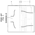
- the normal X-ray projection is performed without rotating the X-ray source around the biological body (namely, with fixed X-ray source). Accordingly, the X-ray projection data are obtained and processed to form a scanogram 30 as represented in Fig. 1.
- the conventional X-ray CT imaging system necessarily requires a lengthy examination time duration until the desirable CT images are obtained, since first the biological body is translated so as to obtain the scanogram 30, secondly this biological body is returned to the home position, and thirdly the biological body is again translated in order to obtain the X-ray CT image data.
- the biological body under medical examination such as a patient must endure such a lengthy and afflictive medical examination.
- the relative position between the X-ray source and the patient differs from each other during the scanogram data acquisition and the CT image data acquisition. Even if, for instance, the first CT imaging position "L 1 " is accurately determined on the scanogram 30, an actual CT imaging position on the patient may be positionally shifted.
- EP-A-0 383 232 discloses a X-ray CT imaging method and system in accordance with the preamble of the independent claims. There, a patient is helically scanned and projection image data are interpolated in order to reconstruct an image of a desired slice.
- DE-C-41 03 588 published on May 27, 1992, discloses a computer tomograph in which a patient is helically scanned. In order to derive an additional shadow image, image data of a predetermined projection angle are processed.
- the present invention has been made in an attempt to solve the above-described problems of the conventional X-ray CT imaging system, and therefore, has an object to provide such X-ray CT imaging method/system capable of producing a scanogram within a short examination time.
- Another object of the present invention is to provide an X-ray CT imaging method/system capable of obtaining a scanogram at high positional precision with respect to CT images of a biological body under medical examination.
- an X-ray CT (computerized tomographic) imaging method comprises the steps as defined in any of claims 1 to 6. portion of the biological body (20); and reconstructing an X-ray CT image (21) of said helically-scanned biological body (20) based upon said first X-ray projection image data, whereby both of said scanogram (22) and said X-ray CT image (21) are substantially simultaneously displayed.
- an X-ray CT (computerized tomographic) imaging system (100:400) comprises the features as defined in any of claims 7 to 12.
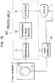
- FIG. 2 there is shown an arrangement of an X-ray CT (computerized tomographic) imaging system 100 according to a first preferred embodiment of the present invention.
- X-ray CT computerized tomographic
- the first X-ray CT imaging system 100 is mainly constructed of an X-ray scanner 2 for performing X-ray scanning operation with respect to a biological body under medical examination such as a patient 20 (shown in Fig. 3) to produce X-ray projection data; a data processing unit 3 for processing the X-ray projection data; a display unit 4 for displaying both of a scanogram and an X-ray CT image; and a main controller 50.
- the data processing unit 3 includes a preprocessing unit 5 for preprocessing the X-ray projection data derived from the X-ray scanner 2 to obtain preprocessed X-ray projection data; a scano data processing unit 6 for processing the preprocessed X-ray projection data to produce scano data; an image reconstructing unit 7 for reconstructing a desirable X-ray CT image from the preprocessed X-ray projection data; and a synthesizing unit 8 for synthesizing the above-described scano data and X-ray CT image data in such a manner that both of the scanogram and the CT image of the biological body are displayed on the same screen of the display unit 4 (will be discussed more in detail).
- a preprocessing unit 5 for preprocessing the X-ray projection data derived from the X-ray scanner 2 to obtain preprocessed X-ray projection data
- a scano data processing unit 6 for processing the preprocessed X-ray projection data to produce scano data
- an image reconstructing unit 7 for reconstructing
- the patient 20 is helically scanned only one time by the X-ray scanner 2 of the first X-ray CT imaging system 100 so as to obtain both of scano data and CT image data. That is to say, since the X-ray projection data are acquired during only one helical scanning operation and thereafter both of the scano data and the CT image data are produced from this series of X-ray projection data, the couch (not shown in detail) on which the patient 20 is laid is translated only one time along a longitudinal direction thereof.
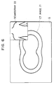
- the helical scanning operation is performed by the X-ray scanner 2 with respect to the patient 20 in the first X-ray CT imaging system 100 of Fig. 2.
- an X-ray detector unit 12 is positioned opposite to an X-ray tube 10, this detector unit 12 is omitted from Fig. 3.
- the X-ray helical scanning operation per se is known from, for instance, U.S. patent No. 4,630,202 issued to Mori, entitled "COMPUTERIZED TOMOGRAPHIC APPARATUS UTILIZING A RADIATION SOURCE", patented on December 16, 1986.
- a series of X-ray projection data obtained by helically scanning the patient 20 is continuously acquired from the X-ray scanner 2 under control of the main controller 50.
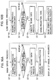
- a preselected projection angle for instance, 0° or 360° (corresponding to the positions 10A, 10B, ... 10N) are read out from the above-described series of helically-scanned X-ray projection data at a first step ST-10.
- the read projection data acquired at the specific projection angle of 0° (360° ) are processed by a curved plane/flat plane transformation, since the X-ray detector unit 12 (see Fig. 2) is constructed of a plurality of detector channels having curved surfaces.
- the plane-transformed projection data are further processed in a high-pass filter (not shown in detail) at a step ST-14.
- the filtered projection data are processed by a scaling process at a step ST-16.
- the scaling-processed projection data (corresponding to the scano data) are displayed as a scanogram 22 (see Fig. 6) on the display unit 4 at a step ST-18. Then, this flow operation is repeated from the previous step ST-10.
- the scanogram 22 of the patient 20 can be obtained by processing only the helically-scanned X-ray projection data acquired at the specific projection angle (0° ) in the scano data processing unit 6 under control of the main controller 50.
- helically-scanned X-ray projection data acquired at another specific projection angle "180° " indicated by a dot line of Fig. 4 are also processed to obtain such a scano data
- the following additional process step is required in the process flow shown in Fig. 4. That is, after the helically-scanned projection data acquired at two specific projection angles of 0° and 180° are read out at the step ST-10 and processed by the curved plane/plane transformation at the step ST-12, only the processed projection data acquired at the specific projection angle 180° are rearranged at a step ST-13. This is because the positional relationship of the detector channel is completely opposite to each other with respect to the projection angles 0° and 180° .
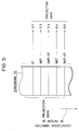
- Fig. 5 represents a so-called “sinogram” 25 constructed of a plurality of projection data "D1", “D2”, ... “D5".
- a desirable scanogram 22 is obtained by arranging these projection data "D1 (angle of 0° )", “D2 (angle of 180° )”, ... “D5 (angle of 360° )” along the longitudinal direction of the patient 20.
- the above-described series of helically-scanned X-ray projection data are preprocessed in the preprocessing unit 5, and thereafter are reconstructed in the image reconstructing unit 7 so as to produce desirable CT image data under control of the main controller.
- Both of this desirable CT image data and the above-mentioned scano data are synthesized in the synthesizing unit 8, so that both of a desirable CT image 21 and a desirable scanogram 22 are simultaneously displayed on the same screen of the display unit 4.
- a line "L x " indicates a position on the patient 20, where this CT image 21 has been obtained.
- this X-ray CT imaging system 100 since both of the scanogram 22 and the CT image 21 can be obtained at the same time by performing only a single helical scanning operation with respect to the patient 20, the entire medical examination time during which the patient 20 must endure can be considerably reduced, as compared with that of the conventional X-ray CT imaging system. Accordingly, since such a lengthy and afflictive medical examination can be mitigated, this X-ray CT imaging system 100 is suitable for a so-called "group diagnosis" in which X-ray imaging portions of patients are previuosly determined and a large number of medical examination processes must be carried out within a limited time period.
- the projection angles of the first X-ray CT imaging system 100 are selected to be 0° , 90° and 180° , any other projection angles such as 1° , 150° , 292° may be freely selected to obtain the scanograms.
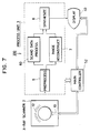
- FIG. 7 an arrangement of an X-ray CT imaging system 200 according to a second preferred embodiment of the present invention will be described.
- a scano data process unit 60 is employed in the process unit 3 and a main controller 52 is employed. Under control of the main controller 52, a series of helically-scanned X-ray projection data are acquired by the X-ray scanner 2 at two specific projection angles of 0° and 90° . Then, one scanogram 26 is obtained as a top view (0° ) and the other scanogram 27 is obtained as a side view (90° ), as indicated in Fig. 10, which are produced in the scano data process unit 60 under control of the main controller 52.
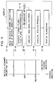
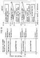
- FIG. 9 An overall operation of the second X-ray CT imaging system 200 will be described. Similarly, acquisition timings (projection angles) of the helically-scanned X-ray projection data and projection data process operations are represented at a lefthand portion of Fig. 9, whereas an operation flow of the second CT imaging system 200 is indicated at a righthand portion of Fig. 9.
- both of the scanogram production and the CT image reconstruction are simultaneously performed at the respective specific projection angles of 0° and 90° , whereas only the CT image reconstruction is carried out at any projection angles other than the specific projection angles.
- a series of helically-scanned X-ray projection data are acquired by the X-ray scanner 2 under control of the main controller 52, and then are preprocessed in the preprocess unit 5 under control of the main controller 52.
- a check is made as to whether or not the helically-scanned projection data has been acquired at the first specific projection angle of 0° . If YES, then the process operation is advanced to a step ST-22 at which the scano data process for the top view 26 (see Fig. 10) is performed in the scano data process unit 60 with respect to the helically-scanned projection data acquired at the angle of 0° .
- the process operation is jumped to a further step ST-23.
- step ST-23 another check is made as to whether or not this helically-scanned projection data has been acquired at the second specific projection angle of 90° . If YES, then the process operation is advanced to the next step ST-24 at which the scano data process for the side view 27 (see Fig. 10) is executed in the scano data process unit 60 under control of the main controller 52.
- the process operation is jumped to a further step ST-25.
- the CT image reconstruction process is carried out with respect to the projection data in the image reconstruction unit 7 under control of the main controller 52. Thereafter, the above-described process operation is repeated from the first step ST-20.
- the resultant CT image 23 produced at the step ST-25 may be displayed in combination with both of the top-viewed scanogram 26 and the side-viewed scanogram 27, as represented in Fig. 10, if required.
- FIG. 11 there is shown an arrangement of an X-ray CT imaging system 300 according to a third preferred embodiment of the present invention.
- a major feature of this third X-ray CT imaging system 300 is such that a scano data process unit 65 is employed in the process unit 3 and is operated in conjunction with a mode selector 80 under control of a main controller 54 to select the operation mode of the third X-ray CT imaging system 300. That is, a selection is made between only scano data process, and also a combination of the scano data process with the CT image reconstruction process via the mode selector 80 by an operator. As shown in Figs. 12A to 12C, the mode selector 80 issues a mode selecting signal of Fig. 12B to the main controller 54. Then, if only the scano data process (scanogram formation) is selected, an X-ray projection control signal shown in Fig.
- the X-ray tube 10 of Fig. 11 is energized in response to this X-ray projection control signal, so that X-ray beams are projected therefrom only at the preselected projection angle of 0° .
- a preselected projection angle e.g., 0°
- the X-ray tube 10 of Fig. 11 is energized in response to this X-ray projection control signal, so that X-ray beams are projected therefrom only at the preselected projection angle of 0° .
- the patient 20 receives only a limited quantity of X-ray dose during this operation mode.
- both of the X-ray tube 10 and the X-ray detector unit 12 are helically scanned around the patient 20, the X-ray beams are intermittently projected from the X-ray tube 10 during the helical scanning operation at the preselected projection angle, which does not correspond to the normal helical scanning operation (will be referred to a "partial X-ray projection").
- the mode selector 80 selects the combination process (namely, the scano data process and the CT image reconstruction process) by the mode selector 80, another mode selecting signal is issued from the main controller 54. Then, the above-described normal helical scanning operation is carried out (will be referred to a "circumferential X-ray projection"), so that while the scanogram data is produced in the scano data process unit 65, the X-ray CT image is reconstructed in the image reconstruction unit 7.
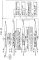
- Fig. 13 represents a flow chart of overall operation by the third X-ray CT imaging system 300 of Fig. 11.
- a check is done as to whether or not the X-ray imaging operation is completed. If NO, then the process operation is advanced to the next step ST-31 at which mode sampling is performed. Then, another check is made as to whether or not only the scano data process is selected. If NO, then the process operation is advanced to the subsequent step ST-33.
- the combination process of the scano data and the CT image reconstruction is selected by the operator via the mode selector 80, the above-described normal helically-scanned X-ray projection data are acquired by the X-ray scanner 2 and thereafter preprocessed in the preprocess unit 5 under control of the main controller 54.
- step ST-34 another check is made as to whether or not the helically-scanned projection data is acquired at the specific projection angle of 0° at a step ST-34. If YES, then the process operation is advanced to the next step ST-35 at which the scano data process is performed by the scano data process unit 65 under control of the main controller 54. To the contrary, if NO at the previous step ST-34, then the process operation is jumped to a step ST-36. Then, the X-ray CT image reconstruction process is performed for this helically-scanned projection data in the image reconstruction unit 7 under control of the main controller.
- step ST-36 After this image reconstruction process has been accomplished at the step ST-36, a further check is made as to whether or not the helically-scanned projection data have been acquired/processed from 0° to 360° (i.e., circumferential X-ray projection process). If NO, then the process operation is returned to the step ST-33, so that a series of projection data process operations is again carried out until the step ST-37. If YES, then the process operation is returned to the first step ST-30, because the combination process operation mode selected by the operator via the mode selector 80 has been completed. Thus, the circumferential X-ray projection (see Fig. 14) is achieved.
- the process operation is advanced to a new step ST-40.
- a predetermined projection angle for instance, 0° in the third X-ray CT imaging system 300 is detected under control of the main controller 54.
- the X-ray beam is projected from the X-ray tube 10 only at the projection angle of 0° at a step ST-42.
- a display region of a scanogram is relatively larger than that of a CT image on a display screen. Furthermore, since an operator observes a CT image with reference to a scanogram, it is suitable for easy observation to display the scanogram with a larger area than that of the CT image on a display screen. To this end, if X-ray beams are projected from the X-ray tube 10 to the patient 20 over the circumferential helical-direction, a total amount of X-ray dose is increased, as compared with that of the partial X-ray projection.
- the mode selector 80 manipulated by an operator is newly employed and can select such a partial X-ray projection in conjunction with the main controller 54 to obtain a scanogram under lower X-ray dose.
- an operator manipulates the mode selector 80 to change the partial X-ray projection mode into the circumferential X-ray projection mode.
- Fig. 15 represents an arrangement of an X-ray CT imaging system 400 according to a fourth preferred embodiment of the present invention.
- a major feature of the fourth X-ray CT imaging system 400 is to employ a scanogram/CT image processing unit 90 in the process unit 3.
- This scanogram/CT image processing unit 90 is capable of performing a scano data process operation and a CT image reconstruction operation.
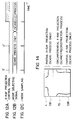
- the entire processing operation of the fourth X-ray CT imaging system 400 is executed in accordance with a flow chart shown in Fig. 16A.
- a first step ST-50 of this flow chart the helically-scanned X-ray projection data are acquired by the X-ray scanner 2 and thereafter are preprocessed by the preprocess unit 5 under control of the main controller 56. Subsequently, a check is done as to whether or not the preprocessed projection data have been acquired at the specific projection angle 0° or 180° at a step ST-52.
- the scano data process operation is carried out for these projection data acquired at the specific projection angle of 0° or 180° at a high speed at the next step ST-54. Then, the CT image reconstruction operation is performed based on these projection data at a step ST-56.
- a resultant CT image (not shown) reconstructed at this step ST-56 may be displayed on the display unit 4 in combination with a scanogram (not shown either) combined in the synthesizer unit 8. If NO at the step ST-52, then the process operation is jumped to the step ST-56 at which the above-described CT image reconstruction process is performed. Then, a series of the above-described highspeed process operation is repeatedly executed.
- the entire processing operation of the fourth X-ray CT imaging system 400 is executed in accordance with a flow chart shown in Fig. 16B. Since the process operations from the step ST-50 to the step ST-54 are identical to those of Fig. 16A, only different process operation will be explained. That is, after the scano data process is accomplished at the step ST-54, the preprocessed X-ray projection data are once stored into a memory (not shown in detail) at the next step ST-55. Thereafter, the stored projection data are read out from the memory and are processed to reconstruct a CT image at a step ST-57.
- the fourth X-ray CT imaging system 400 there are such particular advantages that the overall medical examination time for the patient can be considerably shortened even if both of the scanogram and the X-ray CT image thereof are produced, since only one helical scanning operation is required. Also, a total amount of X-ray dose given to the patient can be reduced, as compared with that of the conventional X-ray CT imaging system.
Description
portion of the biological body (20); and
reconstructing an X-ray CT image (21) of said helically-scanned biological body (20) based upon said first X-ray projection image data, whereby both of said scanogram (22) and said X-ray CT image (21) are substantially simultaneously displayed.
Claims (12)
- An X-ray computerized tomographic imaging method comprising the steps of:scanning a biological body (20) under medical examination in a helical scanning mode, while relatively rotating an X-ray tube (10) around the biological body (20) translated along a longitudinal axis of the biological body (20), to acquire X-ray projection image data about the helically-scanned biological body (20); andreconstructing an X-ray CT image (21) of said helically-scanned biological body (20) based upon said entire X-ray projection image data,
characterized by further comprising the steps of:selecting only X-ray projection image data acquired at a predetermined projection angle from the entire X-ray projection image data obtained at the helical-scanning step; andprocessing said selected X-ray projection image data to produce a scanogram (22) of said helically-scanned biological body (20),
wherein both of said scanogram (22) and said X-ray CT image (21) are substantially simultaneously displayed. - An X-ray computerized tomographic imaging method comprising the steps of:scanning a first portion of a biological body (20) under medical examination in a helical scanning mode, while relatively rotating an X-ray tube (10) around the biological body (20) translated along a longitudinal axis of the biological body (20), to acquire first X-ray projection image data about the helically-scanned first portion of the biological body (20); andreconstructing an X-ray CT image (21) of said helically-scanned first portion of the biological body (20) based upon said first X-ray projection image data,
characterized by further comprising the steps of:producing a scanogram of said first portion of said biological body (20);partially scanning a second portion of said biological body (20) under medical examination by intermittently projecting an X-ray beam to the second portion of the biological body (20) from the X-ray tube (10), to acquire second X-ray projection image data about the helically-scanned second portion of the biological body (20); andprocessing said second X-ray projection image data to produce a scanogram (22) of said partially-scanned second portion of the biological body (20),
wherein both of said scanogram (22) and said X-ray CT image (21) are substantially simultaneously displayed. - An imaging method as claimed in claim 1 or 2, wherein said predetermined projection angle is selected from any of 0°, 90° and 180° with respect to a base line located within a plane perpendicular to said longitudinal axis of the biological body (20).
- An imaging method as claimed in claim 2, wherein said predetermined projection angle is selected from any two combined angles of 0°, 90° and 180° with respect to a base line located within a plane perpendicular to said longitudinal axis of the biological body (20).
- An imaging method as claimed in any of claims 1, 3 and 4, wherein said processing step includes the steps of:executing a curved plane/flat plane transformation with regard to said selected X-ray projection image data acquired at said predetermined projection angle to obtain plane-transformed X-ray projection image data;executing a highpass filtering operation with respect to the plane-transformed X-ray projection image data to obtain filtered X-ray projection image data, andexecuting a density conversion with regard to the filtered X-ray projection image data to obtain density-converted X-ray projection image data, whereby said scanogram (22) is produced based upon the density-converted X-ray projection image data.
- An imaging method as claimed in claim 5, wherein said processing step further includes the step of:rearranging the plane-transformed X-ray projection image data when being acquired at a second projection angle opposite to said predetermined projection angle, whereby the rearranged X-ray projection image data acquired at said second projection angle correspond to the plane-transformed X-ray projection image data acquired at said predetermined projection angle.
- An X-ray computerized tomographic imaging system (100, 400) comprising:scanning means (2) including an X-ray tube (10), for scanning a biological body (20) under medical examination in a helical scanning mode, while relatively rotating said X-ray tube (10) around the biological body (20) translated along a longitudinal axis of the biological body (20), to acquire X-ray projection image data about the helically-scanned biological body (20);CT image reconstruction means (7) for reconstructing an X-ray CT image (21) of said helically-scanned biological body (20) based upon said entire X-ray projection image data; anddisplay means for displaying said X-ray CT image (21),
characterized by further comprising:scano-data processing means (6, 90) for selecting only X-ray projection image data acquired at a predetermined projection angle from the entire X-ray projection image data, and for processing said selected X-ray projection image data to produce a scanogram (22) of said helically-scanned biological body (20),
wherein said display means substantially simultaneously displays both of said scanogram (22) and said X-ray CT image (21). - An X-ray computerized tomographic imaging system (300) comprising:scanning means (2) including an X-ray tube (10), for scanning a first portion of a biological body (20) under medical examination in a helical scanning mode, while relatively rotating an X-ray tube (10) around the biological body (20) translated along a longitudinal axis of the biological body (20), to acquire first X-ray projection image data about the helically-scanned first portion of the biological body (20);CT image reconstruction means (7) for reconstructing an X-ray CT image (21) of said helically-scanned biological body (20) based upon said first X-ray projection image data; anddisplay means (4) for displaying said X-ray CT image (21),
characterized in thatsaid scanning means partially scans a second portion of said biological body (20) by intermittently projecting an X-ray beam of said X-ray tube (10) to the second portion of the biological body (20), to acquire second X-ray projection image data about the partially-scanned second portion of the biological body (20),said system further comprises scano-data processing means (65) for processing said first and second X-ray projection image data to produce a scanogram (22) of said first portion and of said partially-scanned second portion of the biological body (20),
wherein said display means (4) substantially simultaneously displays both of said scanogram (22) and said X-ray CT image (21). - An imaging system (100, 300, 400) as claimed in claim 7 or 8, wherein said predetermined projection angle is selected from any of 0°, 90° and 180° with respect to a base line located within a plane perpendicular to said longitudinal axis of the biological body (20).
- An imaging system (100, 300, 400) as claimed in claim 7 or 8, wherein said scano-data processing means (6, 90) includes:means for executing a curved plane/flat plane transformation with regard to said selected X-ray projection image data acquired at said predetermined projection angle to obtain plane-transformed X-ray projection image data;means for executing a highpass filtering operation with respect to the plane-transformed X-ray projection image data to obtain filtered X-ray projection image data, andmeans for executing a density conversion with regard to the filtered X-ray projection image data to obtain density-converted X-ray projection image data, whereby said scanogram (22) is produced based upon the density-converted X-ray projection image data.
- An imaging system (100, 300, 400) as claimed in claim 10, wherein said scano-data processing means (6, 65, 90) further includes:means for rearranging the plane-transformed X-ray projection image data when being acquired at a second projection angle opposite to said predetermined projection angle, whereby the rearranged X-ray projection image data acquired at said second projection angle correspond to the plane-transformed X-ray projection image data acquired at said predetermined projection angle.
- An imaging system (100, 400) as claimed in claim 7 or 8, further comprising:preprocessing means (5) for preprocessing said X-ray projection image data obtained from said scanning means (2) to produce the preprocessed X-ray projection image data to be supplied to both of said scano-data processing means (6, 90) and said CT image reconstructing means (7); andsynthesizing means (8) for synthesizing said scanogram (22) and said X-ray CT image (21) to be substantially displayed on said display means (4, 40).
Applications Claiming Priority (2)
| Application Number | Priority Date | Filing Date | Title |
|---|---|---|---|
| JP23268891 | 1991-09-12 | ||
| JP232688/91 | 1991-09-12 |
Publications (2)
| Publication Number | Publication Date |
|---|---|
| EP0531993A1 EP0531993A1 (en) | 1993-03-17 |
| EP0531993B1 true EP0531993B1 (en) | 1998-01-07 |
Family
ID=16943232
Family Applications (1)
| Application Number | Title | Priority Date | Filing Date |
|---|---|---|---|
| EP92115493A Expired - Lifetime EP0531993B1 (en) | 1991-09-12 | 1992-09-10 | X-ray computerized tomographic imaging method and imaging system capable of forming scanogram data from helically scanned data |
Country Status (3)
| Country | Link |
|---|---|
| US (1) | US5412702A (en) |
| EP (1) | EP0531993B1 (en) |
| DE (1) | DE69223884T2 (en) |
Cited By (17)
| Publication number | Priority date | Publication date | Assignee | Title |
|---|---|---|---|---|
| WO2004066841A1 (en) | 2003-01-17 | 2004-08-12 | Siemens Aktiengesellschaft | Continuous operation method for a tomography device and corresponding tomography device |
| DE102005061559A1 (en) * | 2005-12-22 | 2007-07-05 | Siemens Ag | Method of operating an x-ray computer tomography apparatus for generating angiograph images having selectable first and second operating modes |
| DE102006003829A1 (en) * | 2006-01-26 | 2007-08-16 | Siemens Ag | X-ray computed tomography and method of operating an X-ray CT scanner |
| US7684538B2 (en) | 2003-04-25 | 2010-03-23 | Rapiscan Systems, Inc. | X-ray scanning system |
| US7724868B2 (en) | 2003-04-25 | 2010-05-25 | Rapiscan Systems, Inc. | X-ray monitoring |
| US7949101B2 (en) | 2005-12-16 | 2011-05-24 | Rapiscan Systems, Inc. | X-ray scanners and X-ray sources therefor |
| US8135110B2 (en) | 2005-12-16 | 2012-03-13 | Rapiscan Systems, Inc. | X-ray tomography inspection systems |
| US8223919B2 (en) | 2003-04-25 | 2012-07-17 | Rapiscan Systems, Inc. | X-ray tomographic inspection systems for the identification of specific target items |
| US8243876B2 (en) | 2003-04-25 | 2012-08-14 | Rapiscan Systems, Inc. | X-ray scanners |
| US8451974B2 (en) | 2003-04-25 | 2013-05-28 | Rapiscan Systems, Inc. | X-ray tomographic inspection system for the identification of specific target items |
| US8804899B2 (en) | 2003-04-25 | 2014-08-12 | Rapiscan Systems, Inc. | Imaging, data acquisition, data transmission, and data distribution methods and systems for high data rate tomographic X-ray scanners |
| US8837669B2 (en) | 2003-04-25 | 2014-09-16 | Rapiscan Systems, Inc. | X-ray scanning system |
| US9001973B2 (en) | 2003-04-25 | 2015-04-07 | Rapiscan Systems, Inc. | X-ray sources |
| US9052403B2 (en) | 2002-07-23 | 2015-06-09 | Rapiscan Systems, Inc. | Compact mobile cargo scanning system |
| US9223052B2 (en) | 2008-02-28 | 2015-12-29 | Rapiscan Systems, Inc. | Scanning systems |
| US9285498B2 (en) | 2003-06-20 | 2016-03-15 | Rapiscan Systems, Inc. | Relocatable X-ray imaging system and method for inspecting commercial vehicles and cargo containers |
| US9429530B2 (en) | 2008-02-28 | 2016-08-30 | Rapiscan Systems, Inc. | Scanning systems |
Families Citing this family (35)
| Publication number | Priority date | Publication date | Assignee | Title |
|---|---|---|---|---|
| US5748696A (en) * | 1993-11-26 | 1998-05-05 | Kabushiki Kaisha Toshiba | Radiation computed tomography apparatus |
| US5594772A (en) * | 1993-11-26 | 1997-01-14 | Kabushiki Kaisha Toshiba | Computer tomography apparatus |
| DE19925395B4 (en) * | 1999-06-02 | 2004-11-25 | Siemens Ag | Method for operating a computed tomography (CT) device |
| DE10001492A1 (en) * | 2000-01-15 | 2001-07-19 | Philips Corp Intellectual Pty | Computer tomography method for generating a scannogram |
| US6823203B2 (en) * | 2001-06-07 | 2004-11-23 | Koninklijke Philips Electronics N.V. | System and method for removing sensitive data from diagnostic images |
| US6914958B2 (en) * | 2001-07-06 | 2005-07-05 | Ge Medical Systems Global Technology Company, Llc | Multi-plane acquisition in digital x-ray radiography |
| US7963695B2 (en) | 2002-07-23 | 2011-06-21 | Rapiscan Systems, Inc. | Rotatable boom cargo scanning system |
| ATE464841T1 (en) * | 2003-02-05 | 2010-05-15 | Koninkl Philips Electronics Nv | DUAL FUNCTION CT SCAN |
| GB0309371D0 (en) | 2003-04-25 | 2003-06-04 | Cxr Ltd | X-Ray tubes |
| GB0309374D0 (en) | 2003-04-25 | 2003-06-04 | Cxr Ltd | X-ray sources |
| GB0309383D0 (en) | 2003-04-25 | 2003-06-04 | Cxr Ltd | X-ray tube electron sources |
| GB0812864D0 (en) | 2008-07-15 | 2008-08-20 | Cxr Ltd | Coolign anode |
| US10483077B2 (en) | 2003-04-25 | 2019-11-19 | Rapiscan Systems, Inc. | X-ray sources having reduced electron scattering |
| GB0309387D0 (en) | 2003-04-25 | 2003-06-04 | Cxr Ltd | X-Ray scanning |
| US9208988B2 (en) | 2005-10-25 | 2015-12-08 | Rapiscan Systems, Inc. | Graphite backscattered electron shield for use in an X-ray tube |
| US9113839B2 (en) | 2003-04-25 | 2015-08-25 | Rapiscon Systems, Inc. | X-ray inspection system and method |
| JP2007526782A (en) | 2003-06-30 | 2007-09-20 | コーニンクレッカ フィリップス エレクトロニクス エヌ ヴィ | Contour and Scout Scan Technology for Pulsed X-ray Large Area CT Detector |
| JP3909059B2 (en) * | 2004-01-07 | 2007-04-25 | ジーイー・メディカル・システムズ・グローバル・テクノロジー・カンパニー・エルエルシー | Radiation tomographic imaging apparatus and imaging method using the same |
| US20060020200A1 (en) * | 2004-07-08 | 2006-01-26 | Medow Joshua E | Artifact-free CT angiogram |
| US7471764B2 (en) | 2005-04-15 | 2008-12-30 | Rapiscan Security Products, Inc. | X-ray imaging system having improved weather resistance |
| US7583781B2 (en) * | 2005-09-22 | 2009-09-01 | Kabushiki Kaisha Toshiba | X-Ray CT apparatus and method of controlling the same |
| US9046465B2 (en) | 2011-02-24 | 2015-06-02 | Rapiscan Systems, Inc. | Optimization of the source firing pattern for X-ray scanning systems |
| JP2008220653A (en) * | 2007-03-13 | 2008-09-25 | Toshiba Corp | X-ray ct apparatus, method for estimating outline of subject and method for reconstituting image |
| GB0809110D0 (en) | 2008-05-20 | 2008-06-25 | Rapiscan Security Products Inc | Gantry scanner systems |
| CN102112055B (en) * | 2008-08-04 | 2016-06-22 | 皇家飞利浦电子股份有限公司 | Interventional imaging and data process |
| GB0816823D0 (en) | 2008-09-13 | 2008-10-22 | Cxr Ltd | X-ray tubes |
| GB0901338D0 (en) | 2009-01-28 | 2009-03-11 | Cxr Ltd | X-Ray tube electron sources |
| US20110019791A1 (en) * | 2009-07-24 | 2011-01-27 | The Research Foundation Of State University Of New York | Selection of optimal views for computed tomography reconstruction |
| US9218933B2 (en) | 2011-06-09 | 2015-12-22 | Rapidscan Systems, Inc. | Low-dose radiographic imaging system |
| DE102013200337B4 (en) * | 2013-01-11 | 2021-11-11 | Siemens Healthcare Gmbh | Method, computer tomograph and computer program product for determining intensity values of an X-ray radiation for dose modulation |
| AU2014212158B2 (en) | 2013-01-31 | 2017-04-20 | Rapiscan Systems, Inc. | Portable security inspection system |
| US10585206B2 (en) | 2017-09-06 | 2020-03-10 | Rapiscan Systems, Inc. | Method and system for a multi-view scanner |
| CN110432920A (en) * | 2019-07-09 | 2019-11-12 | 苏州雷泰智能科技有限公司 | A kind of imaging method and system of radiotherapy CBCT |
| US11212902B2 (en) | 2020-02-25 | 2021-12-28 | Rapiscan Systems, Inc. | Multiplexed drive systems and methods for a multi-emitter X-ray source |
| US11551903B2 (en) | 2020-06-25 | 2023-01-10 | American Science And Engineering, Inc. | Devices and methods for dissipating heat from an anode of an x-ray tube assembly |
Family Cites Families (7)
| Publication number | Priority date | Publication date | Assignee | Title |
|---|---|---|---|---|
| DE2932182A1 (en) * | 1979-08-08 | 1981-02-26 | Siemens Ag | LAYER DEVICE FOR PRODUCING TRANSVERSAL LAYER IMAGES |
| JPS59111738A (en) * | 1982-12-16 | 1984-06-28 | 株式会社東芝 | X-ray tomographic apparatus |
| US4789929A (en) * | 1987-05-14 | 1988-12-06 | Hitachi Medical Corporation | CT system for spirally scanning subject on a movable bed synchronized to X-ray tube revolution |
| JPH0810468B2 (en) * | 1989-01-26 | 1996-01-31 | 株式会社東芝 | Image display device |
| JPH0728862B2 (en) * | 1989-02-13 | 1995-04-05 | 株式会社東芝 | CT device |
| JP2829122B2 (en) * | 1990-11-14 | 1998-11-25 | 株式会社東芝 | Image display device |
| DE4103588C1 (en) * | 1991-02-06 | 1992-05-27 | Siemens Ag, 8000 Muenchen, De |
-
1992
- 1992-09-10 EP EP92115493A patent/EP0531993B1/en not_active Expired - Lifetime
- 1992-09-10 DE DE69223884T patent/DE69223884T2/en not_active Expired - Lifetime
- 1992-09-11 US US07/943,544 patent/US5412702A/en not_active Expired - Lifetime
Cited By (25)
| Publication number | Priority date | Publication date | Assignee | Title |
|---|---|---|---|---|
| US9052403B2 (en) | 2002-07-23 | 2015-06-09 | Rapiscan Systems, Inc. | Compact mobile cargo scanning system |
| US7283607B2 (en) | 2003-01-17 | 2007-10-16 | Siemens Aktiengesellschaft | Continuously operating tomography apparatus and method for the operation thereof |
| WO2004066841A1 (en) | 2003-01-17 | 2004-08-12 | Siemens Aktiengesellschaft | Continuous operation method for a tomography device and corresponding tomography device |
| US8223919B2 (en) | 2003-04-25 | 2012-07-17 | Rapiscan Systems, Inc. | X-ray tomographic inspection systems for the identification of specific target items |
| US9001973B2 (en) | 2003-04-25 | 2015-04-07 | Rapiscan Systems, Inc. | X-ray sources |
| US9020095B2 (en) | 2003-04-25 | 2015-04-28 | Rapiscan Systems, Inc. | X-ray scanners |
| US7684538B2 (en) | 2003-04-25 | 2010-03-23 | Rapiscan Systems, Inc. | X-ray scanning system |
| US7724868B2 (en) | 2003-04-25 | 2010-05-25 | Rapiscan Systems, Inc. | X-ray monitoring |
| US7929663B2 (en) | 2003-04-25 | 2011-04-19 | Rapiscan Systems, Inc. | X-ray monitoring |
| US8837669B2 (en) | 2003-04-25 | 2014-09-16 | Rapiscan Systems, Inc. | X-ray scanning system |
| CN101569531B (en) * | 2003-04-25 | 2011-06-15 | Cxr有限公司 | X-ray scanning system |
| US8804899B2 (en) | 2003-04-25 | 2014-08-12 | Rapiscan Systems, Inc. | Imaging, data acquisition, data transmission, and data distribution methods and systems for high data rate tomographic X-ray scanners |
| US8451974B2 (en) | 2003-04-25 | 2013-05-28 | Rapiscan Systems, Inc. | X-ray tomographic inspection system for the identification of specific target items |
| US8243876B2 (en) | 2003-04-25 | 2012-08-14 | Rapiscan Systems, Inc. | X-ray scanners |
| US9285498B2 (en) | 2003-06-20 | 2016-03-15 | Rapiscan Systems, Inc. | Relocatable X-ray imaging system and method for inspecting commercial vehicles and cargo containers |
| US8625735B2 (en) | 2005-12-16 | 2014-01-07 | Rapiscan Systems, Inc. | X-ray scanners and X-ray sources therefor |
| US8135110B2 (en) | 2005-12-16 | 2012-03-13 | Rapiscan Systems, Inc. | X-ray tomography inspection systems |
| US7949101B2 (en) | 2005-12-16 | 2011-05-24 | Rapiscan Systems, Inc. | X-ray scanners and X-ray sources therefor |
| US8958526B2 (en) | 2005-12-16 | 2015-02-17 | Rapiscan Systems, Inc. | Data collection, processing and storage systems for X-ray tomographic images |
| US7573980B2 (en) | 2005-12-22 | 2009-08-11 | Siemens Aktiengesellschaft | Method for operating an X-ray computer tomograph |
| DE102005061559A1 (en) * | 2005-12-22 | 2007-07-05 | Siemens Ag | Method of operating an x-ray computer tomography apparatus for generating angiograph images having selectable first and second operating modes |
| DE102006003829A1 (en) * | 2006-01-26 | 2007-08-16 | Siemens Ag | X-ray computed tomography and method of operating an X-ray CT scanner |
| US7486763B2 (en) | 2006-01-26 | 2009-02-03 | Siemens Aktiengesellschaft | X ray computer tomograph and method for operating an X ray computer tomograph |
| US9223052B2 (en) | 2008-02-28 | 2015-12-29 | Rapiscan Systems, Inc. | Scanning systems |
| US9429530B2 (en) | 2008-02-28 | 2016-08-30 | Rapiscan Systems, Inc. | Scanning systems |
Also Published As
| Publication number | Publication date |
|---|---|
| EP0531993A1 (en) | 1993-03-17 |
| DE69223884D1 (en) | 1998-02-12 |
| US5412702A (en) | 1995-05-02 |
| DE69223884T2 (en) | 1998-08-27 |
Similar Documents
| Publication | Publication Date | Title |
|---|---|---|
| EP0531993B1 (en) | X-ray computerized tomographic imaging method and imaging system capable of forming scanogram data from helically scanned data | |
| JP4497570B2 (en) | Diagnostic imaging equipment | |
| EP1006878B1 (en) | Real-time dynamic image reconstruction | |
| JP4208985B2 (en) | Method for scanning an object in a computed tomography system and a processor for a computed tomography system | |
| US4674046A (en) | Method and apparatus for obtaining three dimensional tomographic images by interpolation of a plurality of projection slice data bind for obtaining projection data for a chosen slice | |
| EP0080717B1 (en) | An x-ray computerized tomographic apparatus | |
| US6196715B1 (en) | X-ray diagnostic system preferable to two dimensional x-ray detection | |
| EP1324699B1 (en) | Cardiac helical half scan reconstructions for multiple detector row ct | |
| JP5274757B2 (en) | Imaging plan support method and X-ray CT apparatus | |
| KR20060135569A (en) | X-ray ct method and x-ray ct apparatus | |
| JP2007000408A (en) | X-ray ct apparatus | |
| JPH08263638A (en) | System and method for creation of tomographic image of object | |
| JPH07250832A (en) | Method to create tomogram image | |
| US6944261B2 (en) | X-ray computed tomography apparatus | |
| JP4408976B2 (en) | X-ray CT system | |
| JP4434351B2 (en) | Radiation CT | |
| JP3346441B2 (en) | X-ray CT system | |
| JPH09192126A (en) | Image reconstitution processor | |
| JP5461803B2 (en) | X-ray CT system | |
| JP2003204960A (en) | Computed tomographic system | |
| JP3688753B2 (en) | Computed tomography equipment | |
| JPH08187240A (en) | Computed tomography system | |
| JP2002186612A (en) | X-ray ct apparatus | |
| JPH0644405Y2 (en) | X-ray CT system | |
| JP3284109B2 (en) | X-ray computed tomography apparatus |
Legal Events
| Date | Code | Title | Description |
|---|---|---|---|
| PUAI | Public reference made under article 153(3) epc to a published international application that has entered the european phase |
Free format text: ORIGINAL CODE: 0009012 |
|
| 17P | Request for examination filed |
Effective date: 19920910 |
|
| AK | Designated contracting states |
Kind code of ref document: A1 Designated state(s): DE NL |
|
| 17Q | First examination report despatched |
Effective date: 19950306 |
|
| GRAG | Despatch of communication of intention to grant |
Free format text: ORIGINAL CODE: EPIDOS AGRA |
|
| GRAG | Despatch of communication of intention to grant |
Free format text: ORIGINAL CODE: EPIDOS AGRA |
|
| GRAH | Despatch of communication of intention to grant a patent |
Free format text: ORIGINAL CODE: EPIDOS IGRA |
|
| RAP1 | Party data changed (applicant data changed or rights of an application transferred) |
Owner name: KABUSHIKI KAISHA TOSHIBA |
|
| GRAH | Despatch of communication of intention to grant a patent |
Free format text: ORIGINAL CODE: EPIDOS IGRA |
|
| GRAA | (expected) grant |
Free format text: ORIGINAL CODE: 0009210 |
|
| AK | Designated contracting states |
Kind code of ref document: B1 Designated state(s): DE NL |
|
| REF | Corresponds to: |
Ref document number: 69223884 Country of ref document: DE Date of ref document: 19980212 |
|
| PLBE | No opposition filed within time limit |
Free format text: ORIGINAL CODE: 0009261 |
|
| STAA | Information on the status of an ep patent application or granted ep patent |
Free format text: STATUS: NO OPPOSITION FILED WITHIN TIME LIMIT |
|
| 26N | No opposition filed | ||
| PGFP | Annual fee paid to national office [announced via postgrant information from national office to epo] |
Ref country code: DE Payment date: 20110907 Year of fee payment: 20 |
|
| PGFP | Annual fee paid to national office [announced via postgrant information from national office to epo] |
Ref country code: NL Payment date: 20110922 Year of fee payment: 20 |
|
| REG | Reference to a national code |
Ref country code: DE Ref legal event code: R071 Ref document number: 69223884 Country of ref document: DE |
|
| REG | Reference to a national code |
Ref country code: DE Ref legal event code: R071 Ref document number: 69223884 Country of ref document: DE |
|
| REG | Reference to a national code |
Ref country code: NL Ref legal event code: V4 Effective date: 20120910 |
|
| PG25 | Lapsed in a contracting state [announced via postgrant information from national office to epo] |
Ref country code: DE Free format text: LAPSE BECAUSE OF EXPIRATION OF PROTECTION Effective date: 20120911 |