EP0532791A1 - Detachable frame for motorcycle - Google Patents
Detachable frame for motorcycle Download PDFInfo
- Publication number
- EP0532791A1 EP0532791A1 EP91116050A EP91116050A EP0532791A1 EP 0532791 A1 EP0532791 A1 EP 0532791A1 EP 91116050 A EP91116050 A EP 91116050A EP 91116050 A EP91116050 A EP 91116050A EP 0532791 A1 EP0532791 A1 EP 0532791A1
- Authority
- EP
- European Patent Office
- Prior art keywords
- motorcycle
- engine
- frame assembly
- set forth
- frame
- Prior art date
- Legal status (The legal status is an assumption and is not a legal conclusion. Google has not performed a legal analysis and makes no representation as to the accuracy of the status listed.)
- Granted
Links
Images

Classifications
-
- B—PERFORMING OPERATIONS; TRANSPORTING
- B62—LAND VEHICLES FOR TRAVELLING OTHERWISE THAN ON RAILS
- B62M—RIDER PROPULSION OF WHEELED VEHICLES OR SLEDGES; POWERED PROPULSION OF SLEDGES OR SINGLE-TRACK CYCLES; TRANSMISSIONS SPECIALLY ADAPTED FOR SUCH VEHICLES
- B62M7/00—Motorcycles characterised by position of motor or engine
- B62M7/02—Motorcycles characterised by position of motor or engine with engine between front and rear wheels
-
- B—PERFORMING OPERATIONS; TRANSPORTING
- B62—LAND VEHICLES FOR TRAVELLING OTHERWISE THAN ON RAILS
- B62K—CYCLES; CYCLE FRAMES; CYCLE STEERING DEVICES; RIDER-OPERATED TERMINAL CONTROLS SPECIALLY ADAPTED FOR CYCLES; CYCLE AXLE SUSPENSIONS; CYCLE SIDE-CARS, FORECARS, OR THE LIKE
- B62K11/00—Motorcycles, engine-assisted cycles or motor scooters with one or two wheels
- B62K11/02—Frames
-
- B—PERFORMING OPERATIONS; TRANSPORTING
- B62—LAND VEHICLES FOR TRAVELLING OTHERWISE THAN ON RAILS
- B62K—CYCLES; CYCLE FRAMES; CYCLE STEERING DEVICES; RIDER-OPERATED TERMINAL CONTROLS SPECIALLY ADAPTED FOR CYCLES; CYCLE AXLE SUSPENSIONS; CYCLE SIDE-CARS, FORECARS, OR THE LIKE
- B62K25/00—Axle suspensions
- B62K25/005—Axle suspensions characterised by the axle being supported at one end only
Definitions
- This invention relates to a detachable frame for a motorcycle and more particularly to a frame construction for a motorcycle having a detachable member for affording access to the engine of the motorcycle.
- motorcycles are extremely compact assemblies. Normally the motorcycle has a frame assembly that suspends both the front and rear wheels, carries the engine and also carries a seat for the rider. Because of the compact nature of motorcycles and also the high speeds and stresses to which they are attributed, it is desirable for the frame to be not only light but also strong and extremely rigid. However, if the frame is made up of a number of members that are rigidly connected to each other and which have sufficient rigidity, then the accessibility of certain components such as the engine may be deteriorated. With conventional motorcycle frame constructions, it is frequently difficult to access the engine for servicing or to remove it.
- This invention is adapted to be embodied in a motorcycle that is comprised of a frame assembly, a front wheel dirigibly supported by the frame assembly and a rear wheel supported by the frame assembly.
- An internal combustion engine is supported by the frame assembly and drives transmission means for driving the rear wheel.
- the frame assembly includes a member extending along a side of the engine and obstructing the engine In accordance with the invention, this member is detachable from the remainder of the frame for rendering the engine more accessible.
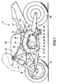
- Figure 1 is a side elevational view of a motorcycle constructed in accordance with an embodiment of the invention.
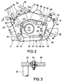
- Figure 2 is an enlarged side view of the portion of the motorcycle showing the frame construction.
- Figure 3 is a cross sectional view taken along the line 3-3 of Figure 2.
- Figure 4 is a partially exploded view showing the frame assembly and the detachability of certain members for removal of the engine and transmission assembly.
- a motorcycle constructed in accordance with an embodiment of the invention is identified generally by the reference numeral 11.
- the motorcycle 11 has a frame, comprised of a main frame assemblage, indicated generally by the reference numeral 12 and which has a construction has will be described later by reference to the remaining figures.
- a front wheel 13 is dirigibly supported by the main frame member 12 by means of a leading arm 14 that has a pair of spaced apart rear pivot joints 15 that are carried by the frame member 12 in a manner to be described.
- An upper arm assembly 16 also has a pivotal connection 17 to a bracket 20 of the main frame member 12 and the upper and lower arms, 16 and 14 are connected to a hub carrier or king pin 18 that rotatably journals the front wheel 13 and which is also steerable relative to the arms 14 and 16.
- a front suspension element 19 carries the upper end of the king pin 18 and connects it to a handle bar assembly 21 for steering movement of the front wheel 13 by the handle bar assembly 21.
- a universal joint is provided in the connection between the handle bar assembly 21 and the king pin or hub carrier 18 so as to accommodate the suspension movement of the front wheel 13.
- a combined spring shock absorber assembly 22 is loaded between the lower arm 14 and the main frame member 12.
- the handle bar assembly 21 is carried by the frame assembly by means of a head pipe 23 that is carried by pairs of angularly disposed stays 24 and 25 which are connected to the main frame member 12 and which form portions of the frame by means of lower joints 26 and 27, respectively.
- a rear wheel 28 is rotatably journalled at the rear end of a trailing arm 29 in a known manner.
- the trailing arm 29 is pivotally supported at its forward end by means of a pair of spaced apart pivot bolts 31 that are affixed in a suitable manner to the main frame member 12.
- a suspension element 32 comprised of a spring and shock absorber assembly is connected at its upper end in a suitable manner to the main frame member 12.
- a linkage system 33 is connected between the trailing arm 29, main frame member 12 and the opposite end of the suspension element 32 for loading the suspension element upon pivotal movement of the trailing arm 29.
- the motorcycle 11 is powered by an internal combustion engine, indicated generally by the reference numeral 34 that is supported within the main frame member 12 in a manner to be described.
- the engine 34 is comprised of a V-2 engine having a forwardly extending cylinder block 35 and a rearwardly extending cylinder block 36, each of which support respective pistons.
- V-2 engine having a forwardly extending cylinder block 35 and a rearwardly extending cylinder block 36, each of which support respective pistons.
- the invention can be employed in conjunction with other types of engines and since the engine itself forms no part of the invention, a more detailed description of it is believed to be unnecessary.
- the engine 34 as is typical with motorcycle practice, has a combined crankcase transmission assembly 37 formed below the cylinder banks 35 and 36 and which not only rotatably journals the crankshaft for the engine, but also contains a change speed transmission, shown partially at 38, which drives a suitable arrangement for driving the rear wheel 28. This may be either a chain or shaft drive.
- a fuel tank 39 is supported at the upper portion of the frame assembly above the main frame member 12 and supplies fuel to the engine 34 in a known manner.
- a seat 41 is carried to the rear of the fuel tank 39 by means of pairs of seat rails 42 that are affixed to lugs 43 of the main frame member 12.
- the main frame member 12 is comprised of a pair of side pieces 44 and 45 which, in conventional constructions, would be identical. These side pieces 44 and 45 are integrally connected to each other by means of a plurality of cross braces or cross members 46, 47,48 and 49.
- the side piece 44 and the side piece 45 in a conventional construction, is of a generally pentagonal shape construction with an open center 51. This is comprised of a lower leg 52, a pair of generally angularly and outwardly inclined side legs 53 and 54 and a inverted V-shaped top member 55.
- This construction provides an extremely rigid arrangement but, however, because of its configuration it encloses and conceals substantial portions of the engine 34. This can make servicing of the engine 34 extremely difficult since access to components such as the carburetors, valve mechanism, etcetera for periodic adjustment can be difficult at best to access. In addition, it is very difficult, with conventional constructions, to remove the engine assembly 34 for servicing.
- the side piece 45 has detachable members 56 and 57 which form the central portions of the upper and lower legs, 55 and 52, respectively.
- the detachable members 56 and 57 have grooved edges 58 that are received within complementary grooves 59 formed in the remaining portion of the side piece 45 so as to insure a rigid connection therebetween.
- Bolt and nut fasteners 61 serve to attach the removal members 56 and 57 to the rest of the side piece 45.
- the engine 34 is mounted within the frame assembly and specifically the main frame member 12 by means of a plurality of mounts 62 that are received in lugs 63 attached to the remainder of the frame member 12.
- mounts 62 that are received in lugs 63 attached to the remainder of the frame member 12.
- the mounting lugs 64 for the lower front suspension pivots 15 also appear.
Abstract
Description
- This invention relates to a detachable frame for a motorcycle and more particularly to a frame construction for a motorcycle having a detachable member for affording access to the engine of the motorcycle.
- As is well known, motorcycles are extremely compact assemblies. Normally the motorcycle has a frame assembly that suspends both the front and rear wheels, carries the engine and also carries a seat for the rider. Because of the compact nature of motorcycles and also the high speeds and stresses to which they are attributed, it is desirable for the frame to be not only light but also strong and extremely rigid. However, if the frame is made up of a number of members that are rigidly connected to each other and which have sufficient rigidity, then the accessibility of certain components such as the engine may be deteriorated. With conventional motorcycle frame constructions, it is frequently difficult to access the engine for servicing or to remove it.
- These problems are particularly acute with a type of motorcycle that employs a trailing arm suspension for the rear wheel and a leading arm suspension for the front wheel. Such motorcycles have the arm suspension members positioned low in the frame and hence employ a sub-frame assemblage that is normally comprised of a pair of spaced apart side members that are integrally connected by means of a plurality of cross braces. These frames are required to provide the requisite support for the pivot points of the front and rear wheel suspensions. Obviously, accessibility of the engine with such frames is extremely difficult.
- It is, therefore, a principal object to this invention to provide an improved frame construction for a motorcycle.
- It is further object to this invention to provide a motorcycle frame construction that is made up of at least one detachable member that can be readily detached for accessibility of the engine for servicing without weakening the overall frame construction.
- It is a further object to this invention to provide an improved frame construction for a motorcycle of the type having arm front and rear wheel suspensions and wherein the frame assembly facilitate ease of servicing of the engine.
- This invention is adapted to be embodied in a motorcycle that is comprised of a frame assembly, a front wheel dirigibly supported by the frame assembly and a rear wheel supported by the frame assembly. An internal combustion engine is supported by the frame assembly and drives transmission means for driving the rear wheel. The frame assembly includes a member extending along a side of the engine and obstructing the engine In accordance with the invention, this member is detachable from the remainder of the frame for rendering the engine more accessible.
- Figure 1 is a side elevational view of a motorcycle constructed in accordance with an embodiment of the invention.
- Figure 2 is an enlarged side view of the portion of the motorcycle showing the frame construction.
- Figure 3 is a cross sectional view taken along the line 3-3 of Figure 2.
- Figure 4 is a partially exploded view showing the frame assembly and the detachability of certain members for removal of the engine and transmission assembly.
- Referring now in detail to the drawings and initially primarily to Figure 1, a motorcycle constructed in accordance with an embodiment of the invention is identified generally by the reference numeral 11. The motorcycle 11 has a frame, comprised of a main frame assemblage, indicated generally by the
reference numeral 12 and which has a construction has will be described later by reference to the remaining figures. - A
front wheel 13 is dirigibly supported by themain frame member 12 by means of a leadingarm 14 that has a pair of spaced apartrear pivot joints 15 that are carried by theframe member 12 in a manner to be described. Anupper arm assembly 16 also has apivotal connection 17 to a bracket 20 of themain frame member 12 and the upper and lower arms, 16 and 14 are connected to a hub carrier orking pin 18 that rotatably journals thefront wheel 13 and which is also steerable relative to thearms - A
front suspension element 19 carries the upper end of theking pin 18 and connects it to ahandle bar assembly 21 for steering movement of thefront wheel 13 by thehandle bar assembly 21. A universal joint is provided in the connection between thehandle bar assembly 21 and the king pin orhub carrier 18 so as to accommodate the suspension movement of thefront wheel 13. - A combined spring
shock absorber assembly 22 is loaded between thelower arm 14 and themain frame member 12. - The
handle bar assembly 21 is carried by the frame assembly by means of ahead pipe 23 that is carried by pairs of angularly disposed stays 24 and 25 which are connected to themain frame member 12 and which form portions of the frame by means oflower joints 26 and 27, respectively. - A
rear wheel 28 is rotatably journalled at the rear end of a trailingarm 29 in a known manner. The trailingarm 29 is pivotally supported at its forward end by means of a pair of spaced apartpivot bolts 31 that are affixed in a suitable manner to themain frame member 12. - A
suspension element 32 comprised of a spring and shock absorber assembly is connected at its upper end in a suitable manner to themain frame member 12. Alinkage system 33 is connected between thetrailing arm 29,main frame member 12 and the opposite end of thesuspension element 32 for loading the suspension element upon pivotal movement of thetrailing arm 29. - The motorcycle 11 is powered by an internal combustion engine, indicated generally by the
reference numeral 34 that is supported within themain frame member 12 in a manner to be described. In the illustrated embodiment, theengine 34 is comprised of a V-2 engine having a forwardly extendingcylinder block 35 and a rearwardly extendingcylinder block 36, each of which support respective pistons. Of course, the invention can be employed in conjunction with other types of engines and since the engine itself forms no part of the invention, a more detailed description of it is believed to be unnecessary. - The
engine 34, as is typical with motorcycle practice, has a combinedcrankcase transmission assembly 37 formed below thecylinder banks rear wheel 28. This may be either a chain or shaft drive. - A
fuel tank 39 is supported at the upper portion of the frame assembly above themain frame member 12 and supplies fuel to theengine 34 in a known manner. Aseat 41 is carried to the rear of thefuel tank 39 by means of pairs ofseat rails 42 that are affixed tolugs 43 of themain frame member 12. - Referring now primarily to the remaining figures, the construction of the
main frame member 12 will be described in detail. Themain frame member 12 is comprised of a pair ofside pieces side pieces cross members side piece 44 and theside piece 45, in a conventional construction, is of a generally pentagonal shape construction with anopen center 51. This is comprised of alower leg 52, a pair of generally angularly and outwardlyinclined side legs top member 55. This construction provides an extremely rigid arrangement but, however, because of its configuration it encloses and conceals substantial portions of theengine 34. This can make servicing of theengine 34 extremely difficult since access to components such as the carburetors, valve mechanism, etcetera for periodic adjustment can be difficult at best to access. In addition, it is very difficult, with conventional constructions, to remove theengine assembly 34 for servicing. - In accordance with the invention, the
side piece 45 hasdetachable members detachable members grooved edges 58 that are received withincomplementary grooves 59 formed in the remaining portion of theside piece 45 so as to insure a rigid connection therebetween. Bolt andnut fasteners 61 serve to attach theremoval members side piece 45. By removal of theremovable members engine 34 may be easily removed from the side of the motorcycle 11 while the remainder of the motorcycle may in fact by kept completely intact and, in fact, can even stand on its own wheels while this removal is taking place. As a result of this, servicing is greatly facilitated and, at the same time, no sacrifice on strength is made. - The
engine 34 is mounted within the frame assembly and specifically themain frame member 12 by means of a plurality ofmounts 62 that are received inlugs 63 attached to the remainder of theframe member 12. In Figure 4, themounting lugs 64 for the lowerfront suspension pivots 15 also appear. - It should be readily apparent from the foregoing description that the described motorcycle frame arrangement permits an extremely strong frame and yet one which offers easy access to the engine for servicing. Of course, the foregoing description is that of a preferred embodiment of the invention and various changes and modifications may be made without departing from the spirit and scope of the invention, and defined by the appended claims.
Claims (8)
- A motorcycle comprised of a frame assembly, a front wheel dirigibly supported by said frame assembly, a rear wheel supported by said frame assembly, and an internal combustion engine supported by said frame assembly and driving transmission means for driving said rear wheel, said frame assembly including a member extending along a side of said engine and obstructing said engine,
characterized in that,
said member (56, 57) being detachable connected to the remainder of said frame assembly (12) for accessing the part of the engine obscured by said member (56, 57) by removal of said member (56, 57). - A motorcycle as set forth in claim 1 wherein the engine (54) is removable from the frame assembly (12) upon removal of the member (56, 57).
- A motorcycle as set forth in claim 1 or 2 wherein the frame assembly (12) is comprised of a pair of spaced apart side pieces (44, 45) integrally connected with each other.
- A motorcycle as set forth in at least one of the preceding claims 1 to 3 wherein the side pieces are integrally connected with each other by means of cross members (46 - 49).
- A motorcycle as set forth in at least one of the preceding claims 1 to 4 wherein each of the side pieces (44, 45) has a generally open configuration comprised of a top portion, a bottom portion and side portions interconnecting the adjacent sides of the top and bottom portions to define the open area (51) therebetween.
- A motorcycle as set forth in at least one of the preceding claims 1 to 5 wherein the removable member (56, 57) comprises at least one of the top and bottom portions of one side piece (44, 45).
- A motorcycle as set forth in at least one of the preceding claims 1 to 6 wherein one of the suspensions for one of the wheels comprises an arm pivotally connected to the frame member (12).
- A motorcycle as set forth in at least one of the preceding claims 1 to 7 wherein each of the wheels are supported from the frame member (12) by a respective arm pivotally connected to the frame member (12).
Priority Applications (3)
| Application Number | Priority Date | Filing Date | Title |
|---|---|---|---|
| US07/757,843 US5248012A (en) | 1991-09-20 | 1991-09-11 | Detachable frame for motorcycle |
| EP91116050A EP0532791B1 (en) | 1991-09-20 | 1991-09-20 | Detachable frame for motorcycle |
| DE69121569T DE69121569T2 (en) | 1991-09-20 | 1991-09-20 | Removable frame for motorcycle |
Applications Claiming Priority (1)
| Application Number | Priority Date | Filing Date | Title |
|---|---|---|---|
| EP91116050A EP0532791B1 (en) | 1991-09-20 | 1991-09-20 | Detachable frame for motorcycle |
Publications (2)
| Publication Number | Publication Date |
|---|---|
| EP0532791A1 true EP0532791A1 (en) | 1993-03-24 |
| EP0532791B1 EP0532791B1 (en) | 1996-08-21 |
Family
ID=8207175
Family Applications (1)
| Application Number | Title | Priority Date | Filing Date |
|---|---|---|---|
| EP91116050A Expired - Lifetime EP0532791B1 (en) | 1991-09-20 | 1991-09-20 | Detachable frame for motorcycle |
Country Status (3)
| Country | Link |
|---|---|
| US (1) | US5248012A (en) |
| EP (1) | EP0532791B1 (en) |
| DE (1) | DE69121569T2 (en) |
Cited By (4)
| Publication number | Priority date | Publication date | Assignee | Title |
|---|---|---|---|---|
| US6085857A (en) * | 1997-08-27 | 2000-07-11 | Honda Giken Kogyo Kabushiki Kaisha | Frame structure of saddle riding type vehicle |
| US20120241237A1 (en) * | 2011-03-21 | 2012-09-27 | Polaris Industries Inc. | Three wheeled vehicle |
| EP3081474A1 (en) * | 2015-03-30 | 2016-10-19 | Honda Motor Co., Ltd. | Front wheel supporting frame structure of saddle-ride type vehicle |
| CN108100128A (en) * | 2013-03-15 | 2018-06-01 | 北极星工业有限公司 | Sulky vehicle |
Families Citing this family (14)
| Publication number | Priority date | Publication date | Assignee | Title |
|---|---|---|---|---|
| US5570753A (en) * | 1995-03-27 | 1996-11-05 | Carlini; Anthony J. | Motorcycle engine and transmission torque-resisting arm |
| US6315072B1 (en) * | 1999-07-29 | 2001-11-13 | Harley-Davidson Motor Company Group, Inc. | Motorcycle engine mounting assembly |
| US6846018B2 (en) * | 2002-05-31 | 2005-01-25 | Harley-Davidson Motor Company Group, Inc. | Motorcycle frame having removable portion |
| US6902023B2 (en) | 2003-07-11 | 2005-06-07 | Harley-Davidson Motor Company Group, Inc. | Engine mounting system for a motorcycle |
| JP4991159B2 (en) * | 2006-01-31 | 2012-08-01 | 本田技研工業株式会社 | Motorcycle body frame |
| US8579063B2 (en) * | 2007-06-29 | 2013-11-12 | Harley-Davidson Motor Company Group, Inc. | Motorcycle having detachable support members |
| US20090008179A1 (en) * | 2007-07-02 | 2009-01-08 | Erik Buell | Motorcycle having a rotatably-mounted engine |
| US20090107754A1 (en) * | 2007-10-31 | 2009-04-30 | Harley-Davidson Motor Company Group, Inc. | Vehicle having a detachable pulley mount |
| JP5112092B2 (en) * | 2008-01-31 | 2013-01-09 | 本田技研工業株式会社 | Rear frame mounting structure for motorcycles |
| US7770683B2 (en) * | 2008-07-16 | 2010-08-10 | Harley-Davidson Motor Company Group, Inc. | Three-wheeled vehicle |
| US8851496B2 (en) * | 2008-07-16 | 2014-10-07 | Harley-Davidson Motor Company Group, LLC | Motorcycle having a multi-piece frame assembly |
| CN103946108B (en) * | 2011-12-28 | 2016-08-24 | 川崎重工业株式会社 | Saddle-type electric vehicle |
| JP7335549B2 (en) * | 2019-11-28 | 2023-08-30 | スズキ株式会社 | Seat rail structure for motorcycle |
| CN113968299A (en) * | 2020-07-22 | 2022-01-25 | Tvs电机股份有限公司 | Frame structure for two-wheeled vehicle |
Citations (3)
| Publication number | Priority date | Publication date | Assignee | Title |
|---|---|---|---|---|
| US4461366A (en) * | 1981-09-18 | 1984-07-24 | Honda Motor Co., Ltd. | Frame for motorcycles |
| US4660854A (en) * | 1984-12-18 | 1987-04-28 | Yamaha Hatsudoki Kabushiki Kaisha | Frame construction for motorcycles |
| GB2191158A (en) * | 1986-06-04 | 1987-12-09 | Honda Motor Co Ltd | Motorcycle with swing-arm front suspension |
Family Cites Families (7)
| Publication number | Priority date | Publication date | Assignee | Title |
|---|---|---|---|---|
| US4523655A (en) * | 1982-11-26 | 1985-06-18 | Deere & Company | Vehicle frame transmission mounting assembly |
| US4799569A (en) * | 1985-08-23 | 1989-01-24 | Honda Giken Kogyo Kabushiki Kaisha | Motorcycle |
| US4721179A (en) * | 1985-10-15 | 1988-01-26 | Honda Giken Kogyo Kabushiki Kaisha | Double swing-arm motorcycle frame |
| US4828069A (en) * | 1986-02-18 | 1989-05-09 | Honda Giken Kogyo Kabushiki Kaisha | Motorcycle |
| US4775025A (en) * | 1986-12-05 | 1988-10-04 | James Parker | Motorcycle with ride height suspension adjustment |
| US4805716A (en) * | 1987-08-12 | 1989-02-21 | Honda Giken Kogyo Kabushiki Kaisha | Motorcycle body frame structure |
| JPH0295997A (en) * | 1988-09-30 | 1990-04-06 | Suzuki Motor Co Ltd | Motorcycle |
-
1991
- 1991-09-11 US US07/757,843 patent/US5248012A/en not_active Expired - Lifetime
- 1991-09-20 EP EP91116050A patent/EP0532791B1/en not_active Expired - Lifetime
- 1991-09-20 DE DE69121569T patent/DE69121569T2/en not_active Expired - Fee Related
Patent Citations (3)
| Publication number | Priority date | Publication date | Assignee | Title |
|---|---|---|---|---|
| US4461366A (en) * | 1981-09-18 | 1984-07-24 | Honda Motor Co., Ltd. | Frame for motorcycles |
| US4660854A (en) * | 1984-12-18 | 1987-04-28 | Yamaha Hatsudoki Kabushiki Kaisha | Frame construction for motorcycles |
| GB2191158A (en) * | 1986-06-04 | 1987-12-09 | Honda Motor Co Ltd | Motorcycle with swing-arm front suspension |
Cited By (8)
| Publication number | Priority date | Publication date | Assignee | Title |
|---|---|---|---|---|
| US6085857A (en) * | 1997-08-27 | 2000-07-11 | Honda Giken Kogyo Kabushiki Kaisha | Frame structure of saddle riding type vehicle |
| US20120241237A1 (en) * | 2011-03-21 | 2012-09-27 | Polaris Industries Inc. | Three wheeled vehicle |
| US9004214B2 (en) * | 2011-03-21 | 2015-04-14 | Polaris Industries Inc. | Three wheeled vehicle |
| US10300971B2 (en) | 2011-03-21 | 2019-05-28 | Polaris Industries Inc. | Three-wheeled vehicle |
| US11572118B2 (en) | 2011-03-21 | 2023-02-07 | Polaris Industries Inc. | Three-wheeled vehicle |
| CN108100128A (en) * | 2013-03-15 | 2018-06-01 | 北极星工业有限公司 | Sulky vehicle |
| CN108100128B (en) * | 2013-03-15 | 2020-08-21 | 北极星工业有限公司 | Two-wheeled vehicle |
| EP3081474A1 (en) * | 2015-03-30 | 2016-10-19 | Honda Motor Co., Ltd. | Front wheel supporting frame structure of saddle-ride type vehicle |
Also Published As
| Publication number | Publication date |
|---|---|
| EP0532791B1 (en) | 1996-08-21 |
| DE69121569T2 (en) | 1997-01-02 |
| US5248012A (en) | 1993-09-28 |
| DE69121569D1 (en) | 1996-09-26 |
Similar Documents
| Publication | Publication Date | Title |
|---|---|---|
| US5248012A (en) | Detachable frame for motorcycle | |
| US5060745A (en) | Engine mounting arrangement and drive mechanism for small snowmobiles | |
| US5042608A (en) | Front-wheel-drive motorcycle | |
| US4817985A (en) | Rear suspension for off-road vehicle | |
| US5575352A (en) | Four-wheeled vehicle | |
| US5921339A (en) | Motorcycle frame | |
| US5211255A (en) | Motorcycle | |
| JP5014858B2 (en) | Body frame structure | |
| US5107952A (en) | Saddle type off-road vehicle | |
| US5531289A (en) | Rear arm pivot structure for motorcycle | |
| US5261504A (en) | Motorcycle frame construction | |
| US4723620A (en) | Motorcycle frame and swing arm support structure | |
| US6581716B1 (en) | All terrain vehicle with rear-facing rear arm bracket | |
| US4756379A (en) | Motorcycle | |
| CA1206103A (en) | Frame structure for a four-wheel drive vehicle | |
| EP0447899B1 (en) | Frame construction for a motorcycle type vehicle | |
| JPH09123973A (en) | Motor cycle | |
| JP2657661B2 (en) | Underbody structure of motorcycle | |
| JPH0818593B2 (en) | Motorcycle | |
| JPH0648362A (en) | Suspension structure for unit swing type engine in motorcycle | |
| JP4035375B2 (en) | Exhaust muffler arrangement structure for motorcycles | |
| JP2583871B2 (en) | Motorcycle | |
| JPH037674A (en) | Steering device mounting structure for vehicle | |
| JP5086155B2 (en) | Front wheel suspension structure for small vehicles | |
| JPS6021113B2 (en) | Chain-driven motorcycle with diamond frame |
Legal Events
| Date | Code | Title | Description |
|---|---|---|---|
| PUAI | Public reference made under article 153(3) epc to a published international application that has entered the european phase |
Free format text: ORIGINAL CODE: 0009012 |
|
| AK | Designated contracting states |
Kind code of ref document: A1 Designated state(s): DE FR IT |
|
| 17P | Request for examination filed |
Effective date: 19930923 |
|
| 17Q | First examination report despatched |
Effective date: 19940701 |
|
| GRAH | Despatch of communication of intention to grant a patent |
Free format text: ORIGINAL CODE: EPIDOS IGRA |
|
| GRAH | Despatch of communication of intention to grant a patent |
Free format text: ORIGINAL CODE: EPIDOS IGRA |
|
| GRAA | (expected) grant |
Free format text: ORIGINAL CODE: 0009210 |
|
| AK | Designated contracting states |
Kind code of ref document: B1 Designated state(s): DE FR IT |
|
| PG25 | Lapsed in a contracting state [announced via postgrant information from national office to epo] |
Ref country code: IT Free format text: LAPSE BECAUSE OF FAILURE TO SUBMIT A TRANSLATION OF THE DESCRIPTION OR TO PAY THE FEE WITHIN THE PRE;WARNING: LAPSES OF ITALIAN PATENTS WITH EFFECTIVE DATE BEFORE 2007 MAY HAVE OCCURRED AT ANY TIME BEFORE 2007. THE CORRECT EFFECTIVE DATE MAY BE DIFFERENT FROM THE ONE RECORDED.SCRIBED TIME-LIMIT Effective date: 19960821 |
|
| REF | Corresponds to: |
Ref document number: 69121569 Country of ref document: DE Date of ref document: 19960926 |
|
| ET | Fr: translation filed | ||
| PLBE | No opposition filed within time limit |
Free format text: ORIGINAL CODE: 0009261 |
|
| STAA | Information on the status of an ep patent application or granted ep patent |
Free format text: STATUS: NO OPPOSITION FILED WITHIN TIME LIMIT |
|
| 26N | No opposition filed | ||
| PGFP | Annual fee paid to national office [announced via postgrant information from national office to epo] |
Ref country code: FR Payment date: 20040908 Year of fee payment: 14 |
|
| PGFP | Annual fee paid to national office [announced via postgrant information from national office to epo] |
Ref country code: DE Payment date: 20040916 Year of fee payment: 14 |
|
| PG25 | Lapsed in a contracting state [announced via postgrant information from national office to epo] |
Ref country code: DE Free format text: LAPSE BECAUSE OF NON-PAYMENT OF DUE FEES Effective date: 20060401 |
|
| PG25 | Lapsed in a contracting state [announced via postgrant information from national office to epo] |
Ref country code: FR Free format text: LAPSE BECAUSE OF NON-PAYMENT OF DUE FEES Effective date: 20060531 |
|
| REG | Reference to a national code |
Ref country code: FR Ref legal event code: ST Effective date: 20060531 |