EP0533907B1 - Electrical device for conversion of molecular weights using dynodes - Google Patents
Electrical device for conversion of molecular weights using dynodes Download PDFInfo
- Publication number
- EP0533907B1 EP0533907B1 EP92910275A EP92910275A EP0533907B1 EP 0533907 B1 EP0533907 B1 EP 0533907B1 EP 92910275 A EP92910275 A EP 92910275A EP 92910275 A EP92910275 A EP 92910275A EP 0533907 B1 EP0533907 B1 EP 0533907B1
- Authority
- EP
- European Patent Office
- Prior art keywords
- dynodes
- dynode
- substance
- molecules
- molecular weight
- Prior art date
- Legal status (The legal status is an assumption and is not a legal conclusion. Google has not performed a legal analysis and makes no representation as to the accuracy of the status listed.)
- Expired - Lifetime
Links
Images

Classifications
-
- B—PERFORMING OPERATIONS; TRANSPORTING
- B01—PHYSICAL OR CHEMICAL PROCESSES OR APPARATUS IN GENERAL
- B01J—CHEMICAL OR PHYSICAL PROCESSES, e.g. CATALYSIS OR COLLOID CHEMISTRY; THEIR RELEVANT APPARATUS
- B01J19/00—Chemical, physical or physico-chemical processes in general; Their relevant apparatus
- B01J19/08—Processes employing the direct application of electric or wave energy, or particle radiation; Apparatus therefor
- B01J19/087—Processes employing the direct application of electric or wave energy, or particle radiation; Apparatus therefor employing electric or magnetic energy
- B01J19/088—Processes employing the direct application of electric or wave energy, or particle radiation; Apparatus therefor employing electric or magnetic energy giving rise to electric discharges
Definitions
- the present invention relates to an apparatus and a method for the conversion of the size of molecules in a process stream, using an electrical method, and can he used either to combine small molecules into larger molecules or to separate larger molecules into smaller molecules.
- Ion impact, fragmentation and ion emission take place on the interior surfaces of the tubes and also ion recombination into new gas species takes place. It can be said that the device operates using electron and ion impact, an electric field, and a very large interior surface area. This can have applications in the petrochemical process industries.
- the output product is crude methanol containing 17% water.
- An alumina catalyst is then used (at 310°C - 320°C and 26 barg pressure) to create dimethyl ether.
- high operating temperatures, high pressures, and costly equipment are necessary.
- the electrical method briefly described above offers significant improvements in that low pressures (such as 0.001 to 0.1 bar) and room temperatures are involved.
- the use of oxygen is not essential, and water need not be part of the reaction unless specified output products containing oxygen are desired.
- a limitation on the electrical device is that a lower throughput of molecules is inherent at lower pressures, so that an equipment designer will naturally attempt to choose the operation pressure of the electrical device to be as high as possible, consistent with a specific conversion reaction.
- Each impact of ion and electron on the tubular reaction surfaces will result in a portion of the impact energy being converted into thermal energy in the material beneath the surface.
- a large value of pressure implies more ion impacts and more conversion reactions per second, and more heat (random thermal energy) generated in the material.
- the semiconducting material on the inside surfaces of the tubular elements may, in certain cases, have a negative temperature coefficient of resistance, so that high pressure operation would lead to heating, lower resistance, and higher leakage currents through the semiconductor layers.
- the present invention comprises an array of dynodes, made of metal, or of glass or ceramic with metal coatings.
- the term "dynode” is intended to mean any type of electrode which, upon being struck at by a single electron, yields several electrons.
- a source of electrons is located at or just outside of the negatively-connected side of the dynode array, and these electrons are accelerated towards the first dynode, striking its surface with energies which may range from several electron volts to more than a hundred electron volts.
- gas pressures of less than 1 Torr are usually used, although operation at pressures several orders of magnitude higher is possible if volume electron/ion interaction effects are to be used for a supplemental improvement in operation.
- a gas which is to be converted is admitted into the chamber on the side of the dynode array which is opposite the electron source. Diffusion of the source gas into the dynode array takes place, with absorption of the gas molecules on the surfaces of the dynodes. Upon impact of the electrons upon the surfaces of the dynodes, several processes take place, the most obvious of which is the disruption of molecular bonding of the absorbed gas.
- a hydrogen ion is created, H+, which immediately is separated from its parent molecule by the action of the electric field. Hydrogen ions thus created are accelerated away from the dynode upon which they were created, moving towards the adjacent, more negative dynode. Upon impact at the adjacent dynode, the hydrogen ion disrupts the bonding of the methane molecules there, and serves as an additional electron source via ion-induced secondary electron emission. The impact of electrons also creates secondary electron emission, with a net gain in electron flux along the dynode array.
- methane molecules are stripped of one or more hydrogen atoms, and have been released from the dynode surface by the energy associated with electron or ion impact, they are accelerated towards the positive end of the dynode array. In such a state of ionization, they will bond readily to other similar species, and to neutrals, upon collision with them, and the formation of carbon-carbon bonds is probable.
- methane source gas By the repeated application of this process in a methane source gas, formation of higher-order mixtures of paraffins, aromatics, olefins, and polyenes takes place. A physical separation of the available hydrogen from the newly-formed higher-order hydrocarbon products is made possible by the electric field.
- Charge exchange is possible because of the flow of electrons through space, and the flow of electrical current through the metallic surfaces of the dynodes.
- Energy for the dissociation is provided by the electric fields between dynodes, which accelerates electrons, hydrogen ions, and complex hydrocarbon ions. Energy transfer is by direct impact at the surfaces of the dynodes. Volume interaction effects also take place at higher pressures, with similar results. Both chemi-absorbed molecules and physically absorbed molecules at the dynode surfaces are affected and transformed by the electron impact process. The higher-order molecules are electrically moved to the region of higher inlet gas pressure, where they are carried by the inlet gas pressure gradient laterally to an outlet stream.
- a condensation stage then removes the higher-order species and the residual methane may be recirculated through the device.
- the same device if operated in a high electron flux mode, could decompose high-order hydrocarbon molecules deposited on the surfaces of the dynodes and a separate collecting electrode held at a slightly positive voltage would attract such fragments. In this mode, lower molecular weight species could be produced from large molecules. It is clear that the admission of gaseous mixtures into this apparatus would result in a variety of output compounds, with a very large number of possibilities which could be considered. It is also clear that the hydrogen ions emerging from the region of the most negative dynode could be either pumped away or could be used to fragment large-molecular-weight hydrocarbon molecules via either a surface interaction or a volume interaction.
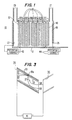
- an electrical device 10 for conversion of hydrocarbon molecular weights using dynodes comprising a chamber 12 with walls constructed of glass, ceramic, or metal, with an inlet gas source 27, an outlet gas port 28, and a hydrogen outlet gas port 29.
- a chamber 12 with walls constructed of glass, ceramic, or metal, with an inlet gas source 27, an outlet gas port 28, and a hydrogen outlet gas port 29.
- an electrode 26 constructed of metal
- another electrode 22 constructed of metal or a suitable semiconducting material, which can serve as an electron source.
- Within the central part of chamber 12 is mounted a plurality of tubular dynode elements 30.
- Each dynode element comprises metallic tubes 32 which are joined together along their outer boundaries in an array so that the axes 33 of the tubes 32 are co-parallel.
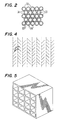
- the tubular elements 32 comprise metal, such as nickel or tantalum, and are bound together by brazing at their boundaries 36, as shown in Figure 2.
- the interior of the tubes 32 are open cylinders 34 with interior surfaces 35 which have secondary-electron-emitting properties. High secondary electron emission yields may be obtained, for example, from layers of a silver-magnesium alloy or a copper-beryllium alloy.
- There is an angle between the tubes' axes 33 and the face 40 of the dynode array which is at least as large as the arc cosine of d/l, where d is the individual tube diameter and l is the individual tube length.
- Each dynode 30 is separated from the adjacent dynodes by a suitable spacing, and each dynode is separately connected electrically to a metallic connection which penetrates the insulating part of the enclosure.
- a potential source 41 is required for each pair of dynodes 30 .
- Each pair of adjacent dynodes 30 has a separate potential source 41 connected between them.
- source 44 is connected from the final dynode 30 to electrode 26, and source 43 is connected from electrode 22 to first dynode 30. Connection of these sources through a glass or ceramic chamber 12 is shown, whereas if a metallic chamber wall is used, separate insulative feed-through connections through the chamber wall would be required.
- the input gas such as methane CH4 is admitted through port 27 into the chamber 10, with an ambient pressure of 10 ⁇ 6 to 1 Torr, for example. Diffusion of the gas into tubes 32 of each dynode occurs, with some of the gas absorbing on the interior walls 35. Electrons originating either from the electron source 22, or from field emission from the metallic coating on face 22, or from cosmic rays, photoemission, or other natural sources, are accelerated along the length of the region from source 22 to first dynode 30, striking the interior walls 35 with substantial energies such as 10 to 100 electron volts. The range of energy values is adjustable with potential source 43.
- a sequence of cascading impacts takes place, which will be described below in detail, which removes hydrogen ions from the absorbed molecules, and allows hydrogen ions to move in the open cylinders 34 towards source 22, while at the same time allows negatively-charged hydrocarbon ions to move in the open cylinders 34 towards the next adjacent dynode 30.
- Subsequent impact of these hydrocarbon ions with other similar charged or neutral species on adjacent dynode 30 causes combination into larger hydrocarbon molecules, which emerge from the face 40 of final dynode 30 and are pumped away into outlet 28.
- the extracted hydrogen ions are carried by the electric field due to potential source 43 towards source 22 where they combine with others of the same species and are pumped away into outlet 29.
- a partition 37 of the chamber 10 prevents mixing of hydrogen with hydrocarbons. Some of the inlet methane will pass, by diffusion, directly into outlet port 28 and will be separated in subsequent condensation stages from the heavier hydrocarbon molecules formed by the device operation, after which the methane may be recirculated back into the inlet stream which feeds port 27.
- the methane molecules 55 may be considered to be absorbed upon the interior walls 35 in a strong, chemi-sorbed bond, which pertains to a surface monolayer, and also in a weaker, multi-molecular-layer bond for additional molecules.
- an incident electron 51 with energy in the range 10 to 100 electron volts, a variety of processes are initiated. Some of the incident electron 51 energy goes to create secondary electrons 57 which are emitted from the wall 35 and which are accelerated in complex trajectories 58 to perpetuate the process at the next impact on the next dynode 30 with wall 35.
- the distorted electric field associated with the presence of the open aperture at the end of the tubes 32 must extend nearly to the region of secondary electron creation, which in turn is within about one to two diameters of the electron-input side of the dynode 30.
- the length l of the tubular elements 32 will be only 2 to perhaps 5 times the diameter d of a tubular element 32.
- the cascading impacts remove hydrogen ion 52 from an absorbed gas molecule 55, also creating a negatively-charged hydrocarbon ion 53, for example CH3 or CH2.
- Some of the incident electron 51 energy imparts sufficient kinetic energy to these ions 52 and 53 so that they depart from their surface creation site and are accelerated along the electric field direction, in complex curved paths.
- the hydrogen ion 52 will subsequently strike an adjacent dynode tube wall 35 with sufficient energy to create secondary electrons which will contribute to the electron cascade required for the process; this is a positive ion feedback effect.
- the same impact of hydrogen ion 52 on wall 35 will also provide sufficient energy to disrupt the bonding of one or several gas molecules 55 absorbed at that site, thus creating more positive hydrogen ions and negative hydrocarbon ions which are released from that site and which are accelerated in opposite directions, thus contributing to the process.
- the hydrocarbon ion 53 acquiring kinetic energy along its path, strikes an adjacent dynode tube wall 35 with energy sufficient to disrupt bonds of molecules 55 at the site of impact, permitting the formation of a carbon-carbon bond at that site, and thus the creation of a higher weight hydrocarbon molecule.
- other processes such as secondary electron production, and hydrogen ion production also may be expected to take place.
- the higher-weight hydrocarbon may not leave the wall 35 immediately upon creation but will be dislodged by a subsequent electron or ion impact.
- the proper amount of charge required for electron current conservation at each impact site is provided by the metal dynodes 30.
- the paths of the electrons and of the ions, as described above, have a length which depends upon the dynode-to-dynode electric field strength, upon the initial kinetic energy of the particles, and their direction of emission from the surface. Inasmuch as the impact-creation of these charged particles involves the combination of many random processes within the wall 35, the direction and initial kinetic energy of the particles will follow a statistical distribution function.
- the alternate orientation of the axes of the tubes in adjacent dynodes is chosen so that ion impact is assured on each dynode, and therefore electrons and ions are not passing through a dynode cylinder without impacting the interior surface 35 of a tubular element 32.
- a dynode may be constructed of an array of flat strips of metal, with the faces co-parallel and inclined at an angle, resembling the well-known "Venetian-blind.” Each such "Venetian-blind" dynode would have the main length direction of the strips oriented orthogonal to the length direction in the adjacent dynodes.
- Other possible dynode shapes include, for example, an array of intersecting strips which form squares (Fig. 5), or plates with an array of connical holes drilled or punched into their surface (Fig. 6).
Abstract
Description
- The present invention relates to an apparatus and a method for the conversion of the size of molecules in a process stream, using an electrical method, and can he used either to combine small molecules into larger molecules or to separate larger molecules into smaller molecules.
- Electrical conversion of molecules of one molecular weight into molecules of another molecular weight has been described in the patent application published as PCT/US88/03228 in WO 89/02868 (Sackinger), corresponding to U.S. Patent Application Ser. No. 07/485,856, filed February 22, 1990, which is a continuation application of Ser. No. 07/102,361, filed September 28, 1987. In that application, an array of tubular elements with a semiconducting layer beneath their interior surfaces is used as a converter. Electron and ion impact upon the interior surfaces of the tubes is used to fragment neutral molecules absorbed there. Energy for electron and ion impact is provided by an electric field, produced by the voltage applied from one side of the array to the opposite side of the array. Ion impact, fragmentation and ion emission take place on the interior surfaces of the tubes and also ion recombination into new gas species takes place. It can be said that the device operates using electron and ion impact, an electric field, and a very large interior surface area. This can have applications in the petrochemical process industries.
- In the petroleum process industries, for many decades a thermal separation process has been applied to crude oil, which is a mixture of hydrocarbons, to separate out various fractions which are subsequently used for specific purposes. For example, diesel fuel, gasoline, naptha, lubricating oils, and asphalts are separated by vaporization and subsequent condensation at appropriate different temperatures and heights in a tower. The resulting yields of refined products are dependent upon the characteristics of the crude oil supplied, which will be different for each petroleum reservoir. The market demand for each category of refined products is variable in time, and therefore the adjustment of the petroleum refining process to changes in input composition and output demand can be difficult and challenging.
- One remedy which has been recognized for many years is to convert larger molecules into smaller ones, a process called cracking, which has been normally accomplished by catalytic action on special surfaces at high temperatures. In this way, for example, an extra quantity of heavy oils can be converted into gasoline, which may be more marketable. Moreover, light naptha, which is a mixture of pentanes and hexanes, may be catalytically cracked to produce ethylene, C₂H₄, a building block molecule for many petrochemicals. Limitations of this approach include the cost of catalysts, the range of input molecules for which they are effective, and the thermal energy required for the process, which is difficult to recover. In addition, the world supply of liquid hydrocarbons is also being consumed, leading to higher prices for liquid feedstocks. Obvious alternatives include the utilization of other natural sources of hydrocarbons which are in more abundant supply: natural gas, and heavy oil. It is clear that an important advantage would be derived from methods to convert natural gas (methane in particular) into higher hydrocarbons such as ethylene, propylene, and larger molecules. Most processes rely on the high-temperature combination of methane and steam to produce hydrogen and carbon monoxide. For example, a Davy-McKee reformer furnace in New Zealand operates at 880°C and 30 bar pressure with a nickel catalyst. After cooling to 35°C at 17 barg pressure, and removal of excess stern, the reformed gas is compressed to 100 barg and passed over a Zn0/Cu0/Al₂0₃ catalyst at 210°C - 240°C. The output product is crude methanol containing 17% water. An alumina catalyst is then used (at 310°C - 320°C and 26 barg pressure) to create dimethyl ether. Clearly, high operating temperatures, high pressures, and costly equipment are necessary. An approach which involves a single-stage direct conversion, and in which the energy which is to be supplied to a reaction is specifically used to accomplish the molecular conversion, with a minimum waste as heat, would represent an improvement.
- The electrical method briefly described above offers significant improvements in that low pressures (such as 0.001 to 0.1 bar) and room temperatures are involved. The use of oxygen is not essential, and water need not be part of the reaction unless specified output products containing oxygen are desired.
- A limitation on the electrical device, however, is that a lower throughput of molecules is inherent at lower pressures, so that an equipment designer will naturally attempt to choose the operation pressure of the electrical device to be as high as possible, consistent with a specific conversion reaction. Each impact of ion and electron on the tubular reaction surfaces will result in a portion of the impact energy being converted into thermal energy in the material beneath the surface. A large value of pressure implies more ion impacts and more conversion reactions per second, and more heat (random thermal energy) generated in the material. The semiconducting material on the inside surfaces of the tubular elements may, in certain cases, have a negative temperature coefficient of resistance, so that high pressure operation would lead to heating, lower resistance, and higher leakage currents through the semiconductor layers. This may lead to self-heating and thermal runaway of the semiconductor layer, followed by destruction of electrical continuity through the layer. Proper choice of materials can prevent this effect, but it is the object of this invention to provide an alternative array of electrodes so that the semiconducting layer is not needed. Thus, higher pressure and higher throughput operation is facilitated.
- It is also possible that in the aforementioned electrical device, operating at high pressures, that the high density of ions in the high-pressure ends of the tubular elements could give rise to an electric field distribution which would depend upon space charge density, which in turn could lead to plasma instabilities and the onset of arc discharge phenomena. In an ideal device, the intensity of the electric field strength would be controlled by external means, and would be time-variable and spatially-variable according to an adaptive and progressively more optimal pattern of applied external voltages. With the tubular elements and their semiconductor layer, this is difficult to accomplish inasmuch as only one voltage is imposed across the ends of the tubes. With this invention hereinafter described, this limitation is removed.
- Although the foregoing discussion of molecular conversion is oriented towards hydrocarbon gaseous conversion, it is obvious that compound gases containing other elements, such as oxygen, chlorine, flourine, bromine, nitrogen, sulfur, hydrogen, silicon, and other elements could be changed in composition in order to accomplish certain benefits, such as the diminution of toxicity prior to release into the natural environment, or the alteration of composition so as to render harmful gases into harmless liquids or gases prior to release into the environment.
- It is the object of the present invention to provide an apparatus and a method for converting substances having a first molecular weight into a substance having a second molecular weight which apparatus or method provides a high throughput and allows operation at high pressures.
- According to the invention these objects are fulfilled by an apparatus as claimed in claim 1, and a method as claimed in claim 15.
- Briefly, the present invention comprises an array of dynodes, made of metal, or of glass or ceramic with metal coatings. The term "dynode" is intended to mean any type of electrode which, upon being struck at by a single electron, yields several electrons. By applying a voltage between one dynode and an adjacent dynode, an electric field is established between dynode surfaces. A source of electrons is located at or just outside of the negatively-connected side of the dynode array, and these electrons are accelerated towards the first dynode, striking its surface with energies which may range from several electron volts to more than a hundred electron volts. For electron flow, gas pressures of less than 1 Torr are usually used, although operation at pressures several orders of magnitude higher is possible if volume electron/ion interaction effects are to be used for a supplemental improvement in operation. A gas which is to be converted is admitted into the chamber on the side of the dynode array which is opposite the electron source. Diffusion of the source gas into the dynode array takes place, with absorption of the gas molecules on the surfaces of the dynodes. Upon impact of the electrons upon the surfaces of the dynodes, several processes take place, the most obvious of which is the disruption of molecular bonding of the absorbed gas. In the case of methane source gas, a hydrogen ion is created, H⁺, which immediately is separated from its parent molecule by the action of the electric field. Hydrogen ions thus created are accelerated away from the dynode upon which they were created, moving towards the adjacent, more negative dynode. Upon impact at the adjacent dynode, the hydrogen ion disrupts the bonding of the methane molecules there, and serves as an additional electron source via ion-induced secondary electron emission. The impact of electrons also creates secondary electron emission, with a net gain in electron flux along the dynode array. Furthermore, once methane molecules are stripped of one or more hydrogen atoms, and have been released from the dynode surface by the energy associated with electron or ion impact, they are accelerated towards the positive end of the dynode array. In such a state of ionization, they will bond readily to other similar species, and to neutrals, upon collision with them, and the formation of carbon-carbon bonds is probable. By the repeated application of this process in a methane source gas, formation of higher-order mixtures of paraffins, aromatics, olefins, and polyenes takes place. A physical separation of the available hydrogen from the newly-formed higher-order hydrocarbon products is made possible by the electric field. Charge exchange is possible because of the flow of electrons through space, and the flow of electrical current through the metallic surfaces of the dynodes. Energy for the dissociation is provided by the electric fields between dynodes, which accelerates electrons, hydrogen ions, and complex hydrocarbon ions. Energy transfer is by direct impact at the surfaces of the dynodes. Volume interaction effects also take place at higher pressures, with similar results. Both chemi-absorbed molecules and physically absorbed molecules at the dynode surfaces are affected and transformed by the electron impact process. The higher-order molecules are electrically moved to the region of higher inlet gas pressure, where they are carried by the inlet gas pressure gradient laterally to an outlet stream. A condensation stage then removes the higher-order species and the residual methane may be recirculated through the device. The same device, if operated in a high electron flux mode, could decompose high-order hydrocarbon molecules deposited on the surfaces of the dynodes and a separate collecting electrode held at a slightly positive voltage would attract such fragments. In this mode, lower molecular weight species could be produced from large molecules. It is clear that the admission of gaseous mixtures into this apparatus would result in a variety of output compounds, with a very large number of possibilities which could be considered. It is also clear that the hydrogen ions emerging from the region of the most negative dynode could be either pumped away or could be used to fragment large-molecular-weight hydrocarbon molecules via either a surface interaction or a volume interaction.
-
- Fig. 1 is a section view of a simplified reaction chamber of a first embodiment of the present invention;
- Fig. 2 is an end section view of part of the parallel array of tubes comprising one dynode of the first embodiment;
- Fig. 3 is a section view of one such tube with an angle between dynode face and tube axis of the first embodiment;
- Fig. 4 illustrates examples of nine dynodes of a third embodiment of the present invention;
- Fig. 5 illustrates an example of a dynode of a fourth embodiment of the present invention; and
- Fig. 6 illustrates examples of four dynodes of a fifth embodiment of the present invention.
- Referring now to the drawings and, in particular, to Figure 1, there is shown an
electrical device 10 for conversion of hydrocarbon molecular weights using dynodes, comprising achamber 12 with walls constructed of glass, ceramic, or metal, with aninlet gas source 27, anoutlet gas port 28, and a hydrogenoutlet gas port 29. Disposed upon or near the inside wall ofchamber 12 is anelectrode 26 constructed of metal, and on the opposite side ofchamber 12 is anotherelectrode 22 constructed of metal or a suitable semiconducting material, which can serve as an electron source. Within the central part ofchamber 12 is mounted a plurality of tubular dynode elements 30. Each dynode element comprises metallic tubes 32 which are joined together along their outer boundaries in an array so that theaxes 33 of the tubes 32 are co-parallel. The tubular elements 32 comprise metal, such as nickel or tantalum, and are bound together by brazing at theirboundaries 36, as shown in Figure 2. The interior of the tubes 32 are open cylinders 34 withinterior surfaces 35 which have secondary-electron-emitting properties. High secondary electron emission yields may be obtained, for example, from layers of a silver-magnesium alloy or a copper-beryllium alloy. There is an angle between the tubes'axes 33 and theface 40 of the dynode array which is at least as large as the arc cosine of d/ℓ, where d is the individual tube diameter and ℓ is the individual tube length. - Each dynode 30 is separated from the adjacent dynodes by a suitable spacing, and each dynode is separately connected electrically to a metallic connection which penetrates the insulating part of the enclosure. For each pair of dynodes 30 a
potential source 41 is required. Each pair of adjacent dynodes 30 has a separatepotential source 41 connected between them. Also,source 44 is connected from the final dynode 30 toelectrode 26, andsource 43 is connected fromelectrode 22 to first dynode 30. Connection of these sources through a glass orceramic chamber 12 is shown, whereas if a metallic chamber wall is used, separate insulative feed-through connections through the chamber wall would be required. - Briefly describing the operation of the device in the mode which increases hydrocarbon molecular weights, the input gas such as methane CH₄ is admitted through
port 27 into thechamber 10, with an ambient pressure of 10⁻⁶ to 1 Torr, for example. Diffusion of the gas into tubes 32 of each dynode occurs, with some of the gas absorbing on theinterior walls 35. Electrons originating either from theelectron source 22, or from field emission from the metallic coating onface 22, or from cosmic rays, photoemission, or other natural sources, are accelerated along the length of the region fromsource 22 to first dynode 30, striking theinterior walls 35 with substantial energies such as 10 to 100 electron volts. The range of energy values is adjustable withpotential source 43. A sequence of cascading impacts takes place, which will be described below in detail, which removes hydrogen ions from the absorbed molecules, and allows hydrogen ions to move in the open cylinders 34 towardssource 22, while at the same time allows negatively-charged hydrocarbon ions to move in the open cylinders 34 towards the next adjacent dynode 30. Subsequent impact of these hydrocarbon ions with other similar charged or neutral species on adjacent dynode 30 causes combination into larger hydrocarbon molecules, which emerge from theface 40 of final dynode 30 and are pumped away intooutlet 28. Concurrently, the extracted hydrogen ions are carried by the electric field due topotential source 43 towardssource 22 where they combine with others of the same species and are pumped away intooutlet 29. Apartition 37 of thechamber 10 prevents mixing of hydrogen with hydrocarbons. Some of the inlet methane will pass, by diffusion, directly intooutlet port 28 and will be separated in subsequent condensation stages from the heavier hydrocarbon molecules formed by the device operation, after which the methane may be recirculated back into the inlet stream which feedsport 27. - To further elaborate upon the details of the separation and recombination mechanism, with reference to Figure 3, the
methane molecules 55 may be considered to be absorbed upon theinterior walls 35 in a strong, chemi-sorbed bond, which pertains to a surface monolayer, and also in a weaker, multi-molecular-layer bond for additional molecules. Wheninterior surfaces 35a are struck by an incident electron 51 with energy in therange 10 to 100 electron volts, a variety of processes are initiated. Some of the incident electron 51 energy goes to createsecondary electrons 57 which are emitted from thewall 35 and which are accelerated incomplex trajectories 58 to perpetuate the process at the next impact on the next dynode 30 withwall 35. In order to extract the secondary electrons thus created in dynode 30, the distorted electric field associated with the presence of the open aperture at the end of the tubes 32 must extend nearly to the region of secondary electron creation, which in turn is within about one to two diameters of the electron-input side of the dynode 30. Thus, the length ℓ of the tubular elements 32 will be only 2 to perhaps 5 times the diameter d of a tubular element 32. The cascading impacts remove hydrogen ion 52 from an absorbedgas molecule 55, also creating a negatively-chargedhydrocarbon ion 53, for example CH₃ or CH₂. Some of the incident electron 51 energy imparts sufficient kinetic energy to theseions 52 and 53 so that they depart from their surface creation site and are accelerated along the electric field direction, in complex curved paths. The hydrogen ion 52 will subsequently strike an adjacentdynode tube wall 35 with sufficient energy to create secondary electrons which will contribute to the electron cascade required for the process; this is a positive ion feedback effect. The same impact of hydrogen ion 52 onwall 35 will also provide sufficient energy to disrupt the bonding of one orseveral gas molecules 55 absorbed at that site, thus creating more positive hydrogen ions and negative hydrocarbon ions which are released from that site and which are accelerated in opposite directions, thus contributing to the process. Thehydrocarbon ion 53, acquiring kinetic energy along its path, strikes an adjacentdynode tube wall 35 with energy sufficient to disrupt bonds ofmolecules 55 at the site of impact, permitting the formation of a carbon-carbon bond at that site, and thus the creation of a higher weight hydrocarbon molecule. At the site of formation of the carbon-carbon bond, other processes such as secondary electron production, and hydrogen ion production also may be expected to take place. In some cases, the higher-weight hydrocarbon may not leave thewall 35 immediately upon creation but will be dislodged by a subsequent electron or ion impact. The net trend of these processes may be summarized by noting that (a) electron and ion kinetic energy is applied to the surface zone where the hydrocarbon molecules are absorbed; (b) rupture of at least one of the hydrocarbon bonds leads to a species separation by means of the electric field; (c) the arrival of an energetic hydrocarbon ion at the surface zone further disrupts absorbed molecules and causes them to form carbon-carbon bonds; and (d) higher weight molecules are moved, as ions, in a direction opposite that of the excess hydrogen, to the end of the device where they are pumped out. - Replenishment of
methane molecules 55 on the surface will take place rapidly by diffusion and deposition from the gas phase present in the tube. Some degree of interaction between charged particles and neutral molecules in the volume space of the tube will also take place, with charge-separation and species separation trends as described for thewalls 35, further enhancing the process. - The proper amount of charge required for electron current conservation at each impact site is provided by the metal dynodes 30.
- The paths of the electrons and of the ions, as described above, have a length which depends upon the dynode-to-dynode electric field strength, upon the initial kinetic energy of the particles, and their direction of emission from the surface. Inasmuch as the impact-creation of these charged particles involves the combination of many random processes within the
wall 35, the direction and initial kinetic energy of the particles will follow a statistical distribution function. The alternate orientation of the axes of the tubes in adjacent dynodes is chosen so that ion impact is assured on each dynode, and therefore electrons and ions are not passing through a dynode cylinder without impacting theinterior surface 35 of a tubular element 32. - Other dynode shapes are possible. For example, as shown in Fig. 4, a dynode may be constructed of an array of flat strips of metal, with the faces co-parallel and inclined at an angle, resembling the well-known "Venetian-blind." Each such "Venetian-blind" dynode would have the main length direction of the strips oriented orthogonal to the length direction in the adjacent dynodes. Other possible dynode shapes include, for example, an array of intersecting strips which form squares (Fig. 5), or plates with an array of connical holes drilled or punched into their surface (Fig. 6).
Claims (15)
- An apparatus for converting a gas containing a substance having a first molecular weight into a gas containing a substance having a second molecular weight comprising:a) a reaction chamber (12) havingi) a gas inlet (27) for letting the substance having the first molecular weight into the chamber, andii) at least one gas outlet (28,29) for letting the substance having the second molecular weight out of the chamber;b) at least one reaction channel for ionizing and reacting molecules of said gas by electron and ion impact upon its interior surface (35); said surface exhibiting secondary-electron-emitting properties; andc) an electrical field generation means for accelerating the electrons and ions in said at least one reaction channel, said means comprisingi) an emitter electrode (22) providing a first electrical potential,ii) a collector electrode (26) providing a final electrical potential, andiii) at least two intermediate electrodes (30) comprising a first intermediate electrode providing a first intermediate electrical potential, and a final intermediate electrode providing a final intermediate electrical potential,
said intermediate electrodes being separated from each other with suitable spacings, providing electrical potentials intermediate between the first and final electrical potentials; andd) at least one electrical potential source (43,44) having terminals connected to the emitter electrode (22), to the at least two intermediate electrodes (30), and to the collector electrode (26) for providing said first, final, and intermediate electrical potentials, respectively;CHARACTERIZED ine) that the at least two intermediate electrodes (30) consist of serially arranged dynodes, each dynode consisting of an electrically-conductive material, or either a glass material or a ceramic material with an electrically-conductive coating; andf) that the at least one reaction channel consists of a series of apertures in said dynodes; said apertures being so arranged that the electrons and ions are not passed through a dynode without impacting on its interior surfaces (35). - The apparatus according to claim 1, CHARACTERIZED in that each of the dynodes comprise at least one tubular element.
- The apparatus according to claim 2, CHARACTERIZED in that the tubular elements have a length of 2 - 5 times their diameter.
- The apparatus according to claim 2, CHARACTERIZED in that each of the tubular elements has a central axis, and that the dynodes are aranged so that their respective axes are at different orientations.
- The apparatus according to claim 4, CHARACTERIZED in that the generated electrical field extends into at least a portion of each said tubular elements.
- The apparatus according to claim 1, CHARACTERIZED in that each of the dynodes comprises flat strips arranged mutually co-parallel in both a main length direction and in a width direction.
- The apparatus according to claim 1, CHARACTERIZED in that each of the dynodes comprises flat strips arranged to form at least one tubular element having a polygonal cross-section.
- The apparatus according to claim 1, CHARACTERIZED in that each of the dynodes comprises a plate having at least one conical opening formed therethrough.
- The apparatus according to any one of claims 1-8, CHARACTERIZED in that the serially arranged dynodes consist of two dynodes.
- The apparatus according to any one of claims 1-8, CHARACTERIZED in that the serally arranged dynodes consist of four dynodes.
- The apparatus according to claim 10, CHARACTERIZED in that at least two of the four dynodes (30) comprises flat strips arranged mutually co-parallel in both a main length direction and a width direction.
- The apparatus according to any one of claims 1-11, CHARACTERIZED in that it further comprises means for time-varying and/or spatially-varying said electrical potentials.
- The apparatus according to any one of claims 1-12, CHARACTERIZED in that the dynodes are arranged into two arrays.
- The apparatus according to any one of claims 1-12, CHARACTERIZED in that the dynodes are arranged into four arrays.
- A method for converting a first substance having a first molecular weight into a second substance having a second molecular weight comprising(a) introducing the first substance into a reaction zone comprising(i) at least one reaction channel having an interior surface exhibiting secondary-electron-emitting properties,(ii) serially arranged dynodes, each dynode consisting of an electrically-conductive material, or either a glass material or a ceramic material with an electrically-conductive coating, and said dynodes having a series of apertures constituting said at least one reaction channel; said apertures being so arranged that the electrons and ions are not passed through a dynode without impacting on its interior surfaces; and(iii) at least one electrical potential source having terminals connected to said dynodes for providing electrical potentials for an electrical field for acceleration of electrons and ions;(b) absorbing said first substance on the interior surface of said at least one reaction channel;(c) reacting said first substance in response to electrons and ions accelerated by the electrical field to create said second substance; and(d) collecting said second substance.
Applications Claiming Priority (3)
| Application Number | Priority Date | Filing Date | Title |
|---|---|---|---|
| US682386 | 1991-04-09 | ||
| US07/682,386 US5141715A (en) | 1991-04-09 | 1991-04-09 | Electrical device for conversion of molecular weights using dynodes |
| PCT/US1992/002936 WO1992018241A1 (en) | 1991-04-09 | 1992-04-08 | Electrical device for conversion of molecular weights using dynodes |
Publications (2)
| Publication Number | Publication Date |
|---|---|
| EP0533907A1 EP0533907A1 (en) | 1993-03-31 |
| EP0533907B1 true EP0533907B1 (en) | 1995-03-22 |
Family
ID=24739469
Family Applications (1)
| Application Number | Title | Priority Date | Filing Date |
|---|---|---|---|
| EP92910275A Expired - Lifetime EP0533907B1 (en) | 1991-04-09 | 1992-04-08 | Electrical device for conversion of molecular weights using dynodes |
Country Status (14)
| Country | Link |
|---|---|
| US (1) | US5141715A (en) |
| EP (1) | EP0533907B1 (en) |
| JP (1) | JP2592572B2 (en) |
| KR (1) | KR970008683B1 (en) |
| AT (1) | ATE120102T1 (en) |
| AU (1) | AU644331B2 (en) |
| CA (1) | CA2084889C (en) |
| DE (1) | DE69201772T2 (en) |
| DK (1) | DK0533907T3 (en) |
| ES (1) | ES2070000T3 (en) |
| FI (1) | FI925572A0 (en) |
| HU (2) | HUT65594A (en) |
| LV (1) | LV10694B (en) |
| WO (1) | WO1992018241A1 (en) |
Families Citing this family (12)
| Publication number | Priority date | Publication date | Assignee | Title |
|---|---|---|---|---|
| US5356524A (en) * | 1993-04-20 | 1994-10-18 | University Of Alaska | Electrical method for conversion of molecular weights of particulates |
| JPH08129007A (en) * | 1994-10-31 | 1996-05-21 | Sekiyu Sangyo Kasseika Center | Analysis of sulfur |
| US7695690B2 (en) | 1998-11-05 | 2010-04-13 | Tessera, Inc. | Air treatment apparatus having multiple downstream electrodes |
| US6176977B1 (en) | 1998-11-05 | 2001-01-23 | Sharper Image Corporation | Electro-kinetic air transporter-conditioner |
| US20050210902A1 (en) | 2004-02-18 | 2005-09-29 | Sharper Image Corporation | Electro-kinetic air transporter and/or conditioner devices with features for cleaning emitter electrodes |
| US20030206837A1 (en) | 1998-11-05 | 2003-11-06 | Taylor Charles E. | Electro-kinetic air transporter and conditioner device with enhanced maintenance features and enhanced anti-microorganism capability |
| US7906080B1 (en) | 2003-09-05 | 2011-03-15 | Sharper Image Acquisition Llc | Air treatment apparatus having a liquid holder and a bipolar ionization device |
| US7724492B2 (en) | 2003-09-05 | 2010-05-25 | Tessera, Inc. | Emitter electrode having a strip shape |
| US7767169B2 (en) | 2003-12-11 | 2010-08-03 | Sharper Image Acquisition Llc | Electro-kinetic air transporter-conditioner system and method to oxidize volatile organic compounds |
| US20060016333A1 (en) | 2004-07-23 | 2006-01-26 | Sharper Image Corporation | Air conditioner device with removable driver electrodes |
| US7833322B2 (en) | 2006-02-28 | 2010-11-16 | Sharper Image Acquisition Llc | Air treatment apparatus having a voltage control device responsive to current sensing |
| US10676679B2 (en) | 2016-03-31 | 2020-06-09 | Lteoil Llc | Multispark reactor |
Family Cites Families (11)
| Publication number | Priority date | Publication date | Assignee | Title |
|---|---|---|---|---|
| US1983028A (en) * | 1929-05-06 | 1934-12-04 | Ionizing Corp Of America | Oil cracking apparatus |
| GB472485A (en) * | 1936-03-23 | 1937-09-23 | Baird Television Ltd | Improvements in or relating to electron discharge devices |
| US2821637A (en) * | 1953-11-30 | 1958-01-28 | Westinghouse Electric Corp | Light image reproduction devices |
| GB813581A (en) * | 1956-04-12 | 1959-05-21 | James Dwyer Mcgee | Improvements in or relating to electron image multiplier apparatus |
| GB1064074A (en) * | 1963-04-03 | 1967-04-05 | Mullard Ltd | Improvements in or relating to image intensifiers |
| US3374380A (en) * | 1965-11-10 | 1968-03-19 | Bendix Corp | Apparatus for suppression of ion feedback in electron multipliers |
| GB1306510A (en) * | 1970-02-11 | 1973-02-14 | Emi Ltd | Electron multiplying electrodes |
| US3677931A (en) * | 1970-03-30 | 1972-07-18 | Louis Richard O Hare | Corona cell for nitrogen and other reactions |
| US3942020A (en) * | 1974-12-09 | 1976-03-02 | Cubic Corporation | Corona discharge ozone generator |
| AU614796B2 (en) * | 1987-09-28 | 1991-09-12 | William M. Sackinger | Electrical device for conversion of molecular weights |
| US5019355A (en) * | 1987-09-28 | 1991-05-28 | University Of Alaska | Electrical device for conversion of molecular weights |
-
1991
- 1991-04-09 US US07/682,386 patent/US5141715A/en not_active Expired - Fee Related
-
1992
- 1992-04-08 AT AT92910275T patent/ATE120102T1/en not_active IP Right Cessation
- 1992-04-08 EP EP92910275A patent/EP0533907B1/en not_active Expired - Lifetime
- 1992-04-08 JP JP4509461A patent/JP2592572B2/en not_active Expired - Lifetime
- 1992-04-08 HU HU9203886A patent/HUT65594A/en unknown
- 1992-04-08 DK DK92910275.4T patent/DK0533907T3/en active
- 1992-04-08 WO PCT/US1992/002936 patent/WO1992018241A1/en active IP Right Grant
- 1992-04-08 AU AU17542/92A patent/AU644331B2/en not_active Ceased
- 1992-04-08 ES ES92910275T patent/ES2070000T3/en not_active Expired - Lifetime
- 1992-04-08 CA CA002084889A patent/CA2084889C/en not_active Expired - Fee Related
- 1992-04-08 DE DE69201772T patent/DE69201772T2/en not_active Expired - Fee Related
- 1992-04-08 HU HU9203886A patent/HU9203886D0/en unknown
- 1992-12-08 FI FI925572A patent/FI925572A0/en unknown
- 1992-12-09 KR KR92703160A patent/KR970008683B1/en not_active IP Right Cessation
- 1992-12-23 LV LVP-92-413A patent/LV10694B/en unknown
Also Published As
| Publication number | Publication date |
|---|---|
| DE69201772T2 (en) | 1995-08-31 |
| US5141715A (en) | 1992-08-25 |
| JPH05508347A (en) | 1993-11-25 |
| ATE120102T1 (en) | 1995-04-15 |
| AU1754292A (en) | 1992-11-17 |
| DK0533907T3 (en) | 1995-08-21 |
| HUT65594A (en) | 1994-07-28 |
| FI925572A (en) | 1992-12-08 |
| AU644331B2 (en) | 1993-12-02 |
| JP2592572B2 (en) | 1997-03-19 |
| FI925572A0 (en) | 1992-12-08 |
| WO1992018241A1 (en) | 1992-10-29 |
| CA2084889A1 (en) | 1992-10-10 |
| EP0533907A1 (en) | 1993-03-31 |
| KR970008683B1 (en) | 1997-05-28 |
| LV10694A (en) | 1995-06-20 |
| CA2084889C (en) | 1999-02-09 |
| HU9203886D0 (en) | 1993-03-29 |
| DE69201772D1 (en) | 1995-04-27 |
| LV10694B (en) | 1995-10-20 |
| ES2070000T3 (en) | 1995-05-16 |
Similar Documents
| Publication | Publication Date | Title |
|---|---|---|
| KR950013066B1 (en) | Electrical device for conversion of molecular weights | |
| EP0533907B1 (en) | Electrical device for conversion of molecular weights using dynodes | |
| TWI801894B (en) | Microwave chemical processing reactor | |
| Liu et al. | Photodetachment and photofragmentation studies of semiconductor cluster anions | |
| CN1195671C (en) | Method and device for producing hydrogen by plasma reformer | |
| Rademann et al. | Size dependence of the gradual transition to metallic properties in isolated mercury clusters | |
| AU705918B2 (en) | A method for providing an ion beam | |
| US5019355A (en) | Electrical device for conversion of molecular weights | |
| AU5815698A (en) | Method and apparatus for producing complex carbon molecules | |
| EP1683180A2 (en) | Carbon nanotube electron ionization sources | |
| Seitz et al. | Polycyclic aromatic hydrocarbon-isomer fragmentation pathways: Case study for pyrene and fluoranthene molecules and clusters | |
| EP0393079B1 (en) | Electrical device for conversion of molecular weights | |
| RU2040331C1 (en) | Apparatus to convert molecules with one molecular mass into molecules with another molecular mass | |
| Kaiser et al. | The Formation of C5H5 isomers as potential key intermediates to polycyclic aromatic hydrocarbon-like molecules | |
| Sattler | Binary metal alloy clusters | |
| EP1456118B1 (en) | Method and device for converting a fuel | |
| Ehbrecht et al. | Laser-driven synthesis of carbon and silicon clusters from gas-phase reactants | |
| Kiermeier et al. | Dissociation Kinetics of Benzene Van‐der‐Waals Cluster Ions | |
| Xenoulis et al. | Size selection by cluster deflection in an electric field | |
| Ticknor | Photodissociation and photoionization of carbon and carbide clusters | |
| Shen | Novel chemistry using molecular beams | |
| Beck et al. | Reprinted with permission from The Journal of Physical Chemistry Vol. 95, No. 21, pp. 8402–8409, 1991© 1991 American Chemical Society | |
| EP1535660A1 (en) | Apparatus for producing at least a fluid reaction product from at least a fluid starting material by a chemical reaction in plasma dielectrically unpeded discharges |
Legal Events
| Date | Code | Title | Description |
|---|---|---|---|
| PUAI | Public reference made under article 153(3) epc to a published international application that has entered the european phase |
Free format text: ORIGINAL CODE: 0009012 |
|
| 17P | Request for examination filed |
Effective date: 19921208 |
|
| AK | Designated contracting states |
Kind code of ref document: A1 Designated state(s): AT BE CH DE DK ES FR GB GR IT LI LU MC NL SE |
|
| 17Q | First examination report despatched |
Effective date: 19931025 |
|
| GRAA | (expected) grant |
Free format text: ORIGINAL CODE: 0009210 |
|
| AK | Designated contracting states |
Kind code of ref document: B1 Designated state(s): AT BE CH DE DK ES FR GB GR IT LI LU MC NL SE |
|
| PG25 | Lapsed in a contracting state [announced via postgrant information from national office to epo] |
Ref country code: GR Free format text: LAPSE BECAUSE OF FAILURE TO SUBMIT A TRANSLATION OF THE DESCRIPTION OR TO PAY THE FEE WITHIN THE PRESCRIBED TIME-LIMIT Effective date: 19950322 |
|
| REF | Corresponds to: |
Ref document number: 120102 Country of ref document: AT Date of ref document: 19950415 Kind code of ref document: T |
|
| REF | Corresponds to: |
Ref document number: 69201772 Country of ref document: DE Date of ref document: 19950427 |
|
| REG | Reference to a national code |
Ref country code: ES Ref legal event code: FG2A Ref document number: 2070000 Country of ref document: ES Kind code of ref document: T3 |
|
| ITF | It: translation for a ep patent filed |
Owner name: GUZZI E RAVIZZA S.R.L. |
|
| ET | Fr: translation filed | ||
| REG | Reference to a national code |
Ref country code: DK Ref legal event code: T3 |
|
| PLBE | No opposition filed within time limit |
Free format text: ORIGINAL CODE: 0009261 |
|
| STAA | Information on the status of an ep patent application or granted ep patent |
Free format text: STATUS: NO OPPOSITION FILED WITHIN TIME LIMIT |
|
| 26N | No opposition filed | ||
| PGFP | Annual fee paid to national office [announced via postgrant information from national office to epo] |
Ref country code: MC Payment date: 19960416 Year of fee payment: 5 |
|
| REG | Reference to a national code |
Ref country code: GB Ref legal event code: 732E |
|
| PG25 | Lapsed in a contracting state [announced via postgrant information from national office to epo] |
Ref country code: MC Effective date: 19971031 |
|
| REG | Reference to a national code |
Ref country code: CH Ref legal event code: PUE Owner name: UNIVERSITY OF ALASKA TRANSFER- DR. WILLIAM M. SACK |
|
| REG | Reference to a national code |
Ref country code: FR Ref legal event code: TP |
|
| NLS | Nl: assignments of ep-patents |
Owner name: WILLIAM M. SACKINGER |
|
| REG | Reference to a national code |
Ref country code: ES Ref legal event code: PC2A Owner name: WILLIAM M. SACKINGER |
|
| PGFP | Annual fee paid to national office [announced via postgrant information from national office to epo] |
Ref country code: FR Payment date: 19990317 Year of fee payment: 8 |
|
| PGFP | Annual fee paid to national office [announced via postgrant information from national office to epo] |
Ref country code: SE Payment date: 19990318 Year of fee payment: 8 Ref country code: GB Payment date: 19990318 Year of fee payment: 8 Ref country code: DE Payment date: 19990318 Year of fee payment: 8 Ref country code: AT Payment date: 19990318 Year of fee payment: 8 |
|
| PGFP | Annual fee paid to national office [announced via postgrant information from national office to epo] |
Ref country code: DK Payment date: 19990319 Year of fee payment: 8 |
|
| PGFP | Annual fee paid to national office [announced via postgrant information from national office to epo] |
Ref country code: CH Payment date: 19990323 Year of fee payment: 8 |
|
| PGFP | Annual fee paid to national office [announced via postgrant information from national office to epo] |
Ref country code: BE Payment date: 19990329 Year of fee payment: 8 |
|
| PGFP | Annual fee paid to national office [announced via postgrant information from national office to epo] |
Ref country code: NL Payment date: 19990331 Year of fee payment: 8 |
|
| PGFP | Annual fee paid to national office [announced via postgrant information from national office to epo] |
Ref country code: ES Payment date: 19990412 Year of fee payment: 8 |
|
| PGFP | Annual fee paid to national office [announced via postgrant information from national office to epo] |
Ref country code: LU Payment date: 19990416 Year of fee payment: 8 |
|
| PG25 | Lapsed in a contracting state [announced via postgrant information from national office to epo] |
Ref country code: LU Free format text: LAPSE BECAUSE OF NON-PAYMENT OF DUE FEES Effective date: 20000408 Ref country code: GB Free format text: LAPSE BECAUSE OF NON-PAYMENT OF DUE FEES Effective date: 20000408 Ref country code: DK Free format text: LAPSE BECAUSE OF NON-PAYMENT OF DUE FEES Effective date: 20000408 Ref country code: AT Free format text: LAPSE BECAUSE OF NON-PAYMENT OF DUE FEES Effective date: 20000408 |
|
| PG25 | Lapsed in a contracting state [announced via postgrant information from national office to epo] |
Ref country code: SE Free format text: LAPSE BECAUSE OF NON-PAYMENT OF DUE FEES Effective date: 20000409 |
|
| PG25 | Lapsed in a contracting state [announced via postgrant information from national office to epo] |
Ref country code: ES Free format text: THE PATENT HAS BEEN ANNULLED BY A DECISION OF A NATIONAL AUTHORITY Effective date: 20000410 |
|
| PG25 | Lapsed in a contracting state [announced via postgrant information from national office to epo] |
Ref country code: LI Free format text: LAPSE BECAUSE OF NON-PAYMENT OF DUE FEES Effective date: 20000430 Ref country code: CH Free format text: LAPSE BECAUSE OF NON-PAYMENT OF DUE FEES Effective date: 20000430 Ref country code: BE Free format text: LAPSE BECAUSE OF NON-PAYMENT OF DUE FEES Effective date: 20000430 |
|
| BERE | Be: lapsed |
Owner name: WILLIAM M. SACKINGER Effective date: 20000430 |
|
| PG25 | Lapsed in a contracting state [announced via postgrant information from national office to epo] |
Ref country code: NL Free format text: LAPSE BECAUSE OF NON-PAYMENT OF DUE FEES Effective date: 20001101 |
|
| GBPC | Gb: european patent ceased through non-payment of renewal fee |
Effective date: 20000408 |
|
| EUG | Se: european patent has lapsed |
Ref document number: 92910275.4 |
|
| REG | Reference to a national code |
Ref country code: CH Ref legal event code: PL |
|
| PG25 | Lapsed in a contracting state [announced via postgrant information from national office to epo] |
Ref country code: FR Free format text: LAPSE BECAUSE OF NON-PAYMENT OF DUE FEES Effective date: 20001229 |
|
| NLV4 | Nl: lapsed or anulled due to non-payment of the annual fee |
Effective date: 20001101 |
|
| PG25 | Lapsed in a contracting state [announced via postgrant information from national office to epo] |
Ref country code: DE Free format text: LAPSE BECAUSE OF NON-PAYMENT OF DUE FEES Effective date: 20010201 |
|
| REG | Reference to a national code |
Ref country code: FR Ref legal event code: ST |
|
| REG | Reference to a national code |
Ref country code: ES Ref legal event code: FD2A Effective date: 20020204 |
|
| REG | Reference to a national code |
Ref country code: DK Ref legal event code: EBP |
|
| PG25 | Lapsed in a contracting state [announced via postgrant information from national office to epo] |
Ref country code: IT Free format text: LAPSE BECAUSE OF NON-PAYMENT OF DUE FEES;WARNING: LAPSES OF ITALIAN PATENTS WITH EFFECTIVE DATE BEFORE 2007 MAY HAVE OCCURRED AT ANY TIME BEFORE 2007. THE CORRECT EFFECTIVE DATE MAY BE DIFFERENT FROM THE ONE RECORDED. Effective date: 20050408 |